
GSC 10.8VLI Professional - Scissors BOSCH - Free user manual and instructions
Find the device manual for free GSC 10.8VLI Professional BOSCH in PDF.
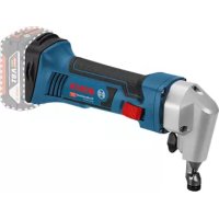
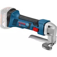
| Product type | Cordless sheet metal shear |
| Brand | Bosch |
| Model | GSC 10.8VLI Professional |
| Article number | 3 601 J26 1.. |
| Nominal voltage | 12 V |
| Battery type | Lithium-ion |
| Recommended batteries | GBA 10.8V... or GBA 12V... |
| Recommended chargers | AL 11..CV or GAL 12..CV |
| No-load stroke rate | 3600 rpm |
| Max. sheet thickness (steel 400 N/mm²) | 1.3 mm |
| Max. sheet thickness (steel 600 N/mm²) | 0.8 mm |
| Max. sheet thickness (steel 800 N/mm²) | 0.6 mm |
| Max. sheet thickness (aluminum 250 N/mm²) | 2.0 mm |
| Minimum radius for curved cuts | 15 mm |
| Weight (according to EPTA 01:2014) | 1.4 – 1.6 kg (depending on battery) |
| Permissible charging temperature | 0 °C to +45 °C |
| Operating and storage temperature | -20 °C to +50 °C |
| Battery protection | Electronic Cell Protection (ECP) against deep discharge |
| Sound pressure level (LpA) | < 70 dB(A) (uncertainty K < 1.5 dB) |
| Vibration (ah) | 3.5 m/s² (uncertainty K < 1.5 m/s²) |
| Number of edges per knife | 4 reversible edges |
| Knife maintenance | Turn by 90° or replace (no resharpening) |
| Knife screw tightening torque | 3–4 Nm |
| Included accessories | Hex key for hex socket screws |
Frequently Asked Questions - GSC 10.8VLI Professional BOSCH
User questions about GSC 10.8VLI Professional BOSCH
0 question about this device. Answer the ones you know or ask your own.
Ask a new question about this device
Download the instructions for your Scissors in PDF format for free! Find your manual GSC 10.8VLI Professional - BOSCH and take your electronic device back in hand. On this page are published all the documents necessary for the use of your device. GSC 10.8VLI Professional by BOSCH.
USER MANUAL GSC 10.8VLI Professional BOSCH
OBJ BUCH-2918-00 Back Page | Tuesday, July 19, 2016 1:57 PM
natural_image
Illustration of a Bosch 120 electric shaver tool (no text or symbols visible)Robert Bosch Power Tools GmbH
70538 Stuttgart
GERMANY
www.bosch-pt.com
1 609 92A 2MV (2016.07) 1/165

GSC 12V-13 Professional
HEAVY DUTY

BOSCH
4 | Deutsch
Deutsch
Sicherheitshinweise
General Power Tool Safety Warnings
WARNING
Read all safety warnings and all instructions. Failure to follow the warnings and
instructions may result in electric shock, fire and/or serious injury.
Save all warnings and instructions for future reference.
The term "power tool" in the warnings refers to your mains-operated (corded) power tool or battery-operated (cordless) power tool.
Work area safety
- Keep work area clean and well lit. Cluttered or dark areas invite accidents.
▶ Do not operate power tools in explosive atmospheres, such as in the presence of flammable liquids, gases or dust. Power tools create sparks which may ignite the dust or fumes.
▶ Keep children and bystanders away while operating a power tool. Distractions can cause you to lose control.
Electrical safety
▶ Power tool plugs must match the outlet. Never modify the plug in any way. Do not use any adapter plugs with earthed (grounded) power tools. Unmodified plugs and matching outlets will reduce risk of electric shock.
▶ Avoid body contact with earthed or grounded surfaces, such as pipes, radiators, ranges and refrigerators. There is an increased risk of electric shock if your body is earthed or grounded.
▶ Do not expose power tools to rain or wet conditions. Water entering a power tool will increase the risk of electric shock.
▶ Do not abuse the cord. Never use the cord for carrying, pulling or unplugging the power tool. Keep cord away from heat, oil, sharp edges and moving parts. Damaged or entangled cords increase the risk of electric shock.
When operating a power tool outdoors, use an extension cord suitable for outdoor use. Use of a cord suitable for outdoor use reduces the risk of electric shock.
▶ If operating a power tool in a damp location is unavoidable, use a residual current device (RCD) protected supply. Use of an RCD reduces the risk of electric shock.
Personal safety
Stay alert, watch what you are doing and use common sense when operating a power tool. Do not use a power tool while you are tired or under the influence of drugs, alcohol or medication. A moment of inattention while operating power tools may result in serious personal injury.
▶ Use personal protective equipment. Always wear eye protection. Protective equipment such as dust mask, non-skid safety shoes, hard hat, or hearing protection used for appropriate conditions will reduce personal injuries.
▶ Prevent unintentional starting. Ensure the switch is in the off-position before connecting to power source and/or battery pack, picking up or carrying the tool. Carrying power tools with your finger on the switch or energising power tools that have the switch on invites accidents.
Remove any adjusting key or wrench before turning the power tool on. A wrench or a key left attached to a rotating part of the power tool may result in personal injury.
▶ Do not overreach. Keep proper footing and balance at all times. This enables better control of the power tool in unexpected situations.
▶ Dress properly. Do not wear loose clothing or jewellery. Keep your hair, clothing and gloves away from moving parts. Loose clothes, jewellery or long hair can be caught in moving parts.
If devices are provided for the connection of dust extraction and collection facilities, ensure these are connected and properly used. Use of dust collection can reduce dust-related hazards.
Power tool use and care
▶ Do not force the power tool. Use the correct power tool for your application. The correct power tool will do the job better and safer at the rate for which it was designed.
▶ Do not use the power tool if the switch does not turn it on and off. Any power tool that cannot be controlled with the switch is dangerous and must be repaired.
▶ Disconnect the plug from the power source and/or the battery pack from the power tool before making any adjustments, changing accessories, or storing power


10 | English
tools. Such preventive safety measures reduce the risk of starting the power tool accidentally.
▶ Store idle power tools out of the reach of children and do not allow persons unfamiliar with the power tool or these instructions to operate the power tool. Power tools are dangerous in the hands of untrained users.
Maintain power tools. Check for misalignment or binding of moving parts, breakage of parts and any other condition that may affect the power tool's operation. If damaged, have the power tool repaired before use. Many accidents are caused by poorly maintained power tools.
- Keep cutting tools sharp and clean. Properly maintained cutting tools with sharp cutting edges are less likely to bind and are easier to control.
▶ Use the power tool, accessories and tool bits etc. in accordance with these instructions, taking into account the working conditions and the work to be performed. Use of the power tool for operations different from those intended could result in a hazardous situation.
Battery tool use and care
▶ Recharge only with the charger specified by the manufacturer. A charger that is suitable for one type of battery pack may create a risk of fire when used with another battery pack.
▶ Use power tools only with specifically designated battery packs. Use of any other battery packs may create a risk of injury and fire.
▶ When battery pack is not in use, keep it away from other metal objects, like paper clips, coins, keys, nails, screws or other small metal objects, that can make a connection from one terminal to another. Shorting the battery terminals together may cause burns or a fire.
▶ Under abusive conditions, liquid may be ejected from the battery; avoid contact. If contact accidentally occurs, flush with water. If liquid contacts eyes, additionally seek medical help. Liquid ejected from the battery may cause irritation or burns.
Service
▶ Have your power tool serviced by a qualified repair person using only identical replacement parts. This will ensure that the safety of the power tool is maintained.
Safety Warnings for Cordless Sheet Metal Shears
The power tool is not suitable for stationary operation. For example, it may not be clamped in a vice or fastened on a workbench.
▶ Only work with the chip deflector 6 mounted. Take care that the chip deflector is not damaged or bent. Danger of injury when working without the chip deflector or when it is damaged. Have a damaged chip deflector replaced immediately by an after-sales service centre for Bosch power tools.
▶ Wear protective gloves while working. Take care that cut sheet parts do not bend toward your body. Sharp burrs develop at the cut steel sheet and can cause injuries to the operator. If required, press bending steel sheet parts away from your body using gloves.
▶ Secure the workpiece. A workpiece clamped with clamping devices or in a vice is held more secure than by hand.
▶ Always wait until the machine has come to a complete stop before placing it down. The tool insert can jam and lead to loss of control over the power tool.
▶ Do not open the battery. Danger of short-circuiting.

Protect the battery against heat, e. g., against continuous intense sunlight, fire, water, and moisture. Danger of explosion.
In case of damage and improper use of the battery, vapours may be emitted. Ventilate the area and seek medical help in case of complaints. The vapours can irritate the respiratory system.
▶ Use the battery only in conjunction with your Bosch power tool. This measure alone protects the battery against dangerous overload.
The battery can be damaged by pointed objects such as nails or screwdrivers or by force applied externally. An internal short circuit can occur and the battery can burn, smoke, explode or overheat.
Product Description and Specifications

Read all safety warnings and all instructions. Failure to follow the warnings and instructions may result in electric shock, fire and/or serious injury.
While reading the operating instructions, unfold the graphics page for the machine and leave it open.
Intended Use
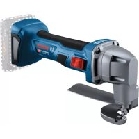
The power tool is intended for cutting sheet metals without loss due to metal chips. It is suitable for curved and straight cuts.
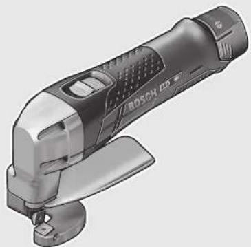
Product Features
The numbering of the product features refers to the illustration of the machine on the graphics page.
1 Battery unlocking button
2 Battery pack
3 Button for charge-control indicator
4 Battery charge-control indicator
5 On/Off switch
6 Chip deflector
7 Handle (insulated gripping surface)
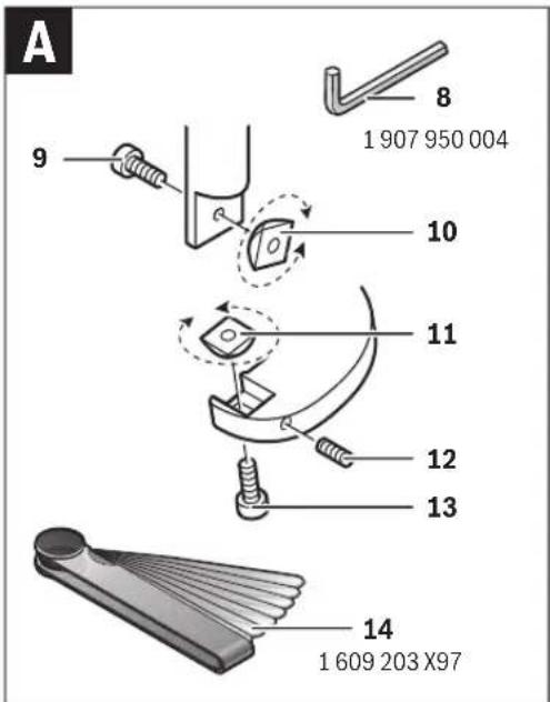
8 Hex key
9 Fastening screw for upper cutter
10 Upper cutter
11 Bottom cutter
12 Adjustment screw, bottom cutter
13 Fastening screw for bottom cutter
14 Setting gauge*
*Accessories shown or described are not part of the standard delivery scope of the product. A complete overview of accessories can be found in our accessories program.


English | 11
Technical Data
Cordless Sheet Metal Shear GSC 12V-13
| Article number | 3 601 J26 1.. | |
| Rated voltage V= 12 | ||
| Stroke rate at no load n_0 | min^1 | 3600 |
| Max. steel sheet cutting capacity ^1) | mm 1.3 | |
| Smallest curve radius mm 15 | ||
| Weight according to EPTA-Procedure 01:2014 | kg 1.4– 1.6 | ^2) |
| Permitted ambient temperature– during charging– during operation ^3) and during storage | °C | 0...+45 |
| °C | -20...+50 | |
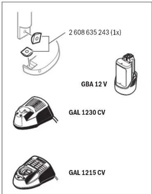
| Recommended batteries | GBA 10,8V...GBA 12V... | |
| Recommended chargers | AL 11.. CVGAL 12.. CV | |
1) to 400 N/mm ^2 with reference to steel sheet
2) depending on the battery pack being used
3) limited performance at temperatures <0 °C
Noise/Vibration Information
Sound emission values determined according to EN 60745.
Typically the A-weighted sound pressure level of the product is less than 70 dB(A). Uncertainty K < 1.5 dB.
The noise level when working can exceed 80 dB(A).
Wear hearing protection!
Vibration total values a_h (triax vector sum) and uncertainty K determined according to EN 60745-2-8: a_h=3.5 m/s ; K<1.5 m/s^2 .
The vibration level given in this information sheet has been measured in accordance with a standardised test given in EN 60745 and may be used to compare one tool with another. It may be used for a preliminary assessment of exposure.
The declared vibration emission level represents the main applications of the tool. However if the tool is used for different applications, with different accessories or insertion tools or is poorly maintained, the vibration emission may differ. This may significantly increase the exposure level over the total working period.
An estimation of the level of exposure to vibration should also take into account the times when the tool is switched off or when it is running but not actually doing the job. This may significantly reduce the exposure level over the total working period. Identify additional safety measures to protect the operator from the effects of vibration such as: maintain the tool and the accessories, keep the hands warm, organisation of work patterns.
Assembly
Battery Charging
▶ Use only the chargers listed in the technical data. Only these chargers are matched to the lithium-ion battery of your power tool.
Note: The battery supplied is partially charged. To ensure full capacity of the battery, completely charge the battery in the battery charger before using your power tool for the first time.
The lithium-ion battery can be charged at any time without reducing its service life. Interrupting the charging procedure does not damage the battery.
Battery Charge-control Indication
The three green LEDs of the battery charge-control indicator 4 indicate the charge condition of the battery 2. For safety reasons, it is only possible to check the status of the charge condition when the machine is at a standstill.
- To indicate the charge condition, press and hold button 3 of the switched off machine.
| LED | Capacity |
| Continuous lighting 3 x green | ≥ 2/3 |
| Continuous lighting 2 x green | ≥ 1/3 |
| Continuous lighting 1 x green | <1/3 |
| Flashing light 1 x green | Reserve |
Removing the battery
- To remove the battery 2, press the unlocking buttons 1 and pull the battery out of the machine to the rear. Do not exert any force.
Operation
Starting Operation
Inserting the battery
▶ Use only original Bosch lithium-ion batteries with the voltage listed on the nameplate of your power tool. Using other batteries can lead to injuries and pose a fire hazard.
Note: Use of batteries not suitable for the machine can lead to malfunctions of or cause damage to the power tool.
- Insert the charged battery 2 into the handle until it can be felt to engage and faces flush against the handle.
Switching On and Off
- To start the machine, push the On/Off switch 5 forward so that the "I" is indicated on the switch.
- To switch off the machine, push the On/Off switch 5 toward the rear so that the "0" is indicated on the switch.
To save energy, only switch the power tool on when using it.
The lithium-ion battery is protected against deep discharging by the "Electronic Cell Protection (ECP)". When the battery is empty, the machine is switched off by means of a protective circuit: The inserted tool no longer rotates.
Note: If the machine should automatically switch off because of a discharged or overheated battery, make sure to set the machine's On/Off switch 5 to off. Charge the battery and allow it to cool down before restarting the machine. Otherwise the battery can become damaged.


12 | English
Working Advice
- Apply the power tool to the workpiece only when switched on.
- Guide the power tool at an angle of 80 to 90^ to the surface of the sheet metal and do not tilt it to the side.
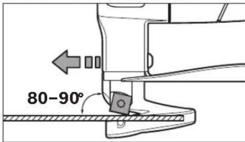
- Guide the machine evenly and with light feed in the cutting direction. Excessive feed significantly reduces the service life of the saw blade and can cause damage to the power tool.
- When cutting curves, make sure not to tilt the power tool laterally and work with low feed rate only.
Maximum Steel Sheet Cutting Capacity
The maximum steel sheet cutting capacity d_max depends on the strength properties of the material to be cut.
The machine allows for cutting of metal sheet to the following thicknesses:
| Material Max. strength property [N/mm^2] | d_max [mm] |
Steel 400 1.3
600 0.8
800 0.6
Aluminium 250 2.0
Adjusting Cutter Clearance a
Before any work on the machine itself (e.g. maintenance, tool change, etc.) as well as during transport and storage, remove the battery from the power tool.
There is danger of injury when unintentionally actuating the On/Off switch.
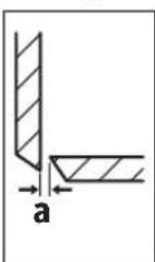
The cutter clearance a (gap between the cutters) depends on the sheet thickness d_max to be cut.
The cutter clearance a should be 10 % of the sheet thickness d_max (e.g. 0.1 mm cutter clearance for 1 mm sheet thickness).
For softer or more ductile materials, the clearance a must be decreased; for harder or more brittle materials, increased.
- Loosen the fastening screw 13 for the bottom cutter. Adjust the required cutter clearance a with the adjustment screw 12. The upper cutter 10 and the bottom cutter 11 may not touch each other. Check the clearance with the setting gauge 14. Retighten the fastening screw 13 for the bottom cutter with a tightening torque of 3–4 Nm.
Temperature Dependent Overload Protection
If used in accordance with its intended use, the power tool cannot be overloaded. If the power tool is overloaded or not kept within the permitted battery temperature range, the stroke rate is reduced or the power tool switches off. When the stroke rate is reduced, the power tool will not run at full stroke rate again until the permitted battery temperature has been reached. If it automatically shuts down, switch the power tool off, allow the battery to cool down, then switch the power tool back on.
Recommendations for Optimal Handling of the Battery
Protect the battery against moisture and water.
Store the battery only within a temperature range between -20°C and 50°C. As an example, do not leave the battery in the car in summer.
A significantly reduced working period after charging indicates that the battery is used and must be replaced.
Observe the notes for disposal.
Maintenance and Service
Maintenance and Cleaning
Before any work on the machine itself (e.g. maintenance, tool change, etc.) as well as during transport and storage, remove the battery from the power tool. There is danger of injury when unintentionally actuating the On/Off switch.
▶ For safe and proper working, always keep the machine and ventilation slots clean.
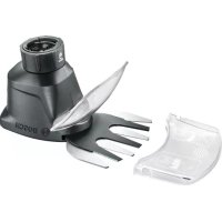
Replace the blade (see figure A)
The upper cutter 10 and the bottom cutter 11 are identical, have four cutting edges each, and can be exchanged with each other.
Turn or replace the cutters in good time. Only sharp application tools achieve good cutting capacity and make the machine last longer.
- To replace the upper cutter 10, loosen the fastening screw 9; to replace the bottom cutter 11, loosen the fastening screw 13.
- Turn the cutter by 90^ or install a new cutter. When installing the bottom cutter 11, pay attention that it faces against the adjustment screw 12.
Note: Turn the cutter only in the direction indicated in the figure and insert a new cutter only in the position shown in the figure. Cutting is not possible with an incorrectly inserted cutter.
- Retighten the fastening screw 9 for the upper cutter and the fastening screw 13 for the bottom cutter with a tightening torque of 3–4 Nm. Check the cutter clearance a (see "Adjusting Cutter Clearance a", page 12).
Upper cutter 10 and bottom cutter 11 may not be reground.


After-sales Service and Application Service
Our after-sales service responds to your questions concerning maintenance and repair of your product as well as spare parts. Exploded views and information on spare parts can also be found under:
www.bosch-pt.com
Bosch's application service team will gladly answer questions concerning our products and their accessories.
In all correspondence and spare parts orders, please always include the 10-digit article number given on the nameplate of the product.
Great Britain
Robert Bosch Ltd. (B.S.C.)
P.O. Box 98
Broadwater Park
North Orbital Road
Denham
Uxbridge
UB 9 5HJ
At www.bosch-pt.co.uk you can order spare parts or arrange the collection of a product in need of servicing or repair.
Tel. Service: (0344) 7360109
E-Mail: boschservicecentre@bosch.com
Ireland
Origo Ltd.
Unit 23 Magna Drive
Magna Business Park
City West
Dublin 24
Tel. Service: (01) 4666700
Fax: (01) 4666888
Australia, New Zealand and Pacific Islands
Robert Bosch Australia Pty. Ltd.
Power Tools
Locked Bag 66
Clayton South VIC 3169
Customer Contact Center
Inside Australia:
Phone: (01300) 307044
Fax: (01300) 307045
Inside New Zealand
Phone: (0800) 543353
Fax: (0800) 428570
Outside AU and NZ:
Phone: +61 3 95415555
www.bosch.com.au
Republic of South Africa
Customer service
Hotline: (011) 6519600
Gauteng - BSC Service Centre
35 Roper Street, New Centre
Johannesburg
Tel.: (011) 4939375
Fax: (011) 4930126
E-Mail: bsctools@icon.co.za
KZN - BSC Service Centre
Unit E, Almar Centre
143 Crompton Street
Pinetown
Tel.: (031) 7012120
Fax: (031) 7012446
E-Mail: bsc.dur@za.bosch.com
Western Cape - BSC Service Centre
Democracy Way, Prosperity Park
Milnerton
Tel.: (021) 5512577
Fax: (021) 5513223
E-Mail: bsc@zsd.co.za
Bosch Headquarters
Midrand, Gauteng
Tel.: (011) 6519600
Fax: (011) 6519880
E-Mail: rbsa-hq.pts@za.bosch.com
Transport
The contained lithium-ion batteries are subject to the Dangerous Goods Legislation requirements. The user can transport the batteries by road without further requirements.
When being transported by third parties (e.g.: air transport or forwarding agency), special requirements on packaging and labelling must be observed. For preparation of the item being shipped, consulting an expert for hazardous material is required.
Dispatch batteries only when the housing is undamaged. Tape or mask off open contacts and pack up the battery in such a manner that it cannot move around in the packaging.
Please also observe possibly more detailed national regulations.
Disposal

The machine, rechargeable batteries, accessories and packaging should be sorted for environmental-friendly recycling.
Do not dispose of power tools and batteries/rechargeable batteries into household waste!
Only for EC countries:
According to the European Guideline 2012/19/EU, power tools that are no longer usable, and according to the European Guideline 2006/66/EC, defective or used battery packs/batteries, must be collected separately and disposed of in an environmentally correct manner.
Batteries no longer suitable for use can be directly returned at:
Great Britain
Robert Bosch Ltd. (B.S.C.)
P.O. Box 98
Broadwater Park
North Orbital Road
Denham
Uxbridge
UB 9 5HJ


14 | Français
At www.bosch-pt.co.uk you can order spare parts or arrange the collection of a product in need of servicing or repair. Tel. Service: (0344) 7360109 E-Mail: boschservicecentre@bosch.com
Battery packs/batteries:
Li-ion: Please observe the instructions in section "Transport", page 13.
Subject to change without notice.
Français
natural_image
Simple line drawing of two angled metal profiles with a dimension label 'a' (no text or symbols beyond the label)Robert Bosch (France) S.A.S.
natural_image
Simple line drawing of a corner joint with labeled dimension 'a' (no text or symbols beyond label)natural_image
Simple line drawing of two angled metal profiles with a labeled dimension 'a' (no text or symbols beyond the label)natural_image
Simple line drawing of two angled metal profiles with a dimension label 'a' (no text or symbols beyond the label)Bosch Service Center
Telegrafvej 3
2750 Ballerup
På www.bosch-pt.dk kan der online bestilles reservedele eller oprettes en reparations ordre.
Tlf. Service Center: 44898855
Fax: 44898755
E-Mail: vaerktoej@dk.bosch.com
Transport
Bosch Service Center
Telegrafvej 3
2750 Ballerup
Danmark
Tel.: (08) 7501820 (inom Sverige)
Fax: (011) 187691
Transport
13 Skrue for underkniv
14 Innstillingsslære*
natural_image
Simple line drawing of a corner joint with labeled dimension 'a' (no text or symbols beyond label)natural_image
Simple line drawing of two angled metal profiles with a labeled dimension 'a' (no text or symbols beyond the label)Robert Bosch Sp. z o.o.
Bosch Service Center PT
K Vápence 1621/16
692 01 Mikulov
natural_image
Simple line drawing of two angled metal profiles with a labeled dimension 'a' (no text or symbols beyond the label)natural_image
Simple line drawing of a corner joint with labeled dimension 'a' (no text or symbols beyond label)natural_image
Diagram showing two angled metal profiles with a labeled dimension 'a' (no text or symbols beyond the label)natural_image
Diagram showing two shaded rectangular shapes with a dimension arrow labeled 'a' (no text or symbols beyond label)natural_image
Simple line drawing of a corner with a shaded wall and an arrow labeled 'a' (no text or symbols beyond the label)natural_image
Simple line drawing of two geometric shapes with arrows, no text or symbols presentTel. service scule electrice: (021) 4057540
Fax: (021) 4057566
E-Mail: infoBSC@ro.bosch.com
natural_image
Simple line drawing of a corner with a shaded wall and an arrow labeled 'a' (no text or symbols beyond the label)natural_image
Simple line drawing of a corner with a shaded wall and an arrow labeled 'a' (no text or symbols beyond the label)natural_image
Simple line drawing of two geometric shapes with a dimension label 'a' (no text or symbols present)natural_image
Simple line drawing of a corner with a shaded wall and an arrow labeled 'a' (no text or symbols beyond the label)natural_image
Simple line drawing of two angled metal profiles with a dimension label 'a' (no text or symbols beyond the label)Mechanics and Electronics Ltd. PT/SAX-ASA
298 Bojeong-dong Giheung-gu
Yongin-si, Gyeonggi-do, 446-913
Republic of Korea
080-955-0909
운반
Athen Subjective Originality of the Praganda from the Praganda Originality of the Praganda from the Praganda Originality of the Praganda from the Praganda Originality of the Praganda from the Praganda Originality of the Praganda from the Praganda Originality of the Praganda from the Praganda Originality of the Praganda from the Praganda Originality of the Praganda from the Praganda Originality of the Praganda From the Praganda Originality of the Praganda From the Praganda Originality of the Praganda From the Praganda Originality of the Praganda From the Praganda Originality of the Praganda From the Praganda Originality of the Praganda From the Praganda Originality of the Praganda From the Praganda Originality of the Praganda From the Praganda Originality of thePraganda From the Praganda Originality of the Praganda From the Praganda Originality of the Praganda From the Praganda Originality of the Praganda From the Praganda Originality of the Praganda From the Praganda Originality of the Praganda From the Praganda Originality of the Praganda From the Praganda Originality of the Praganda From the PragandaOriginality of the Praganda From the PragandaOriginality of the Praganda From the PragandaOriginality of the Praganda From the PragandaOriginality of the Praganda From the PragandaOriginality of the Praganda From the PragandaOriginality of the Praganda From the PragandaOriginality of the Praganda From the PragandaOriginality of the Praganda From 1998, 2000, 2001, 2002, 2003, 2004, 2005, 2006, 2007, 2008, 2009, 2010, 2011, 2012, 2013, 2014, 2015, 2016, 2017, 2018, 2019, 2020, 2021, 2022, 2023, 2024, 2025, 2026, 2027, 2028, 2029, 2030, 2031, 2032, 2033, 2034, 2035, 2036, 2037, 2038, 2039, 2040, 2041, 2042, 2043, 2044, 2045, 2046, 2047, 2048, 2049, 2050, 2051, 2052, 2053, 2054, 2055, 2056, 2057, 2058, 2059, 2060, 2061, 2062, 2063, 2064, 2065, 2066, 2067, 2068, 2069, 2070, 2071, 2072, 2073, 2074, 2075, 2076, 2077, 2078, 2079, 2080, 2081, 2082, 2083, 2084, 2085, 2086, 2087, 2088, 2089, 2090, 2091, 2092, 2093, 2094, 2095, 2096, 2097, 2098, 2099, 2100
natural_image
Simple geometric diagram showing two perpendicular lines with a labeled dimension 'a' (no text or symbols beyond the label)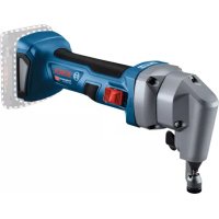
- GSC 12V-13 Professional
- BOSCH
- | Deutsch
- Deutsch
- Sicherheitshinweise
- General Power Tool Safety Warnings
- WARNING
- Save all warnings and instructions for future reference.
- Work area safety
- Electrical safety
- Personal safety
- Power tool use and care
- | English
- Battery tool use and care
- Service
- Safety Warnings for Cordless Sheet Metal Shears
- Product Description and Specifications
- Intended Use
- Product Features
- English | 11
- Noise/Vibration Information
- Wear hearing protection!
- Assembly
- Battery Charging
- Battery Charge-control Indication
- Removing the battery
- Operation
- Starting Operation
- Inserting the battery
- Switching On and Off
- | English
- Working Advice
- Maximum Steel Sheet Cutting Capacity
- Adjusting Cutter Clearance a
- Temperature Dependent Overload Protection
- Recommendations for Optimal Handling of the Battery
- Maintenance and Service
- Maintenance and Cleaning
- Replace the blade (see figure A)
- After-sales Service and Application Service
- www.bosch-pt.com
- Great Britain
- Ireland
- Australia, New Zealand and Pacific Islands
- Republic of South Africa
- Customer service
- Gauteng - BSC Service Centre
- KZN - BSC Service Centre
- Western Cape - BSC Service Centre
- Bosch Headquarters
- Transport
- Disposal
- Only for EC countries:
- | Français
- Battery packs/batteries:
- Français
- 운반
Brand : BOSCH
Model : GSC 10.8VLI Professional
Category : Scissors