
SnowLine 620E III - Snow blower AL-KO - Free user manual and instructions
Find the device manual for free SnowLine 620E III AL-KO in PDF.
| Product type | Thermal snow blower |
| Brand | AL-KO |
| Model | SnowLine 620E III |
| Engine | 4-stroke gasoline engine |
| Transmission | 6 forward speeds, 2 reverse speeds |
| Drive system | Bowden cables |
| Discharge direction | Adjustable via crank |
| Discharge height | Adjustable via lever |
| Lighting | Yes, with switch |
| Heated handles | Yes, with switch |
| Safety devices | Two clutch levers, shear bolts, ejection chute guard |
| Delivery contents | Snow auger, lower and upper handlebar, control panel, ejection chute, mounting kit, keys, spare shear bolts |
| Intended use | Clearing fresh snow on stable surfaces (asphalt, paving stones) |
| Maintenance | Lubrication of the auger, oil change, check shear bolts, check tire pressure |
| Cleaning | Use the cleaning tool provided, do not spray water |
| Storage | Empty the fuel tank, remove the ignition key, store in a dry place |
| Warranty | Legal warranty against manufacturing defects, wear parts excluded |
Frequently Asked Questions - SnowLine 620E III AL-KO
User questions about SnowLine 620E III AL-KO
0 question about this device. Answer the ones you know or ask your own.
Ask a new question about this device
Download the instructions for your Snow blower in PDF format for free! Find your manual SnowLine 620E III - AL-KO and take your electronic device back in hand. On this page are published all the documents necessary for the use of your device. SnowLine 620E III by AL-KO.
USER MANUAL SnowLine 620E III AL-KO
AL-KO KOBER GROUP Kottz, Germany
This documentation or excerpts therefrom may not be reproduced or disclosed to third parties without the express permission of the AL-KO KOBER GROUP.
| i SnowLine 620 E III | |
| 113067 | |
| 4 | Petrol / unleaded ≥ 86 octane, E10 | |
| 0,95 | Recommendation: SAE 5W-30 | |
| Loncin LC180FDS | |
| 302 cm³ | |
| 6,2 kW / 3600 min-1 | |
| 2000 +/- 200 min-1 | |
| 134 x 62 x 113 cm | |
| 96 kg | |
| 62 cm | |
| ○i | SnowLine 620 E III |
| 51 cm | |
| km/h | 3,8 km/h +/- 0,3 |
| km/h | 1,9 km/h +/- 0,3 |
| ah = max 4,5 m/s² K = 1,5 m/s² | |
| LpA = 90,6 dB(A) K = 2,5 dB(A) | |
| LwA = 102 dB(A) | |
| 33,02 cm / 13" | |
1 About these operating instructions. 28
1.1 Symbols on the title page 29
1.2 Legends and signal words 29
2 Product description 29
2.1 Designated use 29
2.2 Possible foreseeable misuse 29
2.3 Safety and protective devices 29
2.4 Scope of supply for 620 E III. 30
2.5 Symbols on the appliance 30
2.5.1 Safety signs.. 30
2.5.2 Operating signs 31
2.6 Product overview - 620 E III (01) ...... 31
3 Safety instructions. 32
3.1 Safety instructions in accordance with ISO 8437, Annex A. 32
3.2 Safety instructions relating to operation 34
3.3 Handling of petrol and oil 34
4 Unpacking appliance (02) 35
5Assembly. 35
5.1 Fitting the lower brace (03, 04) 35
5.2 Fitting the operating panel (05) 35
5.3 Installing and adjusting Bowden cables for travel and worm drives (06 - 11) 36
5.4 Adjusting the Bowden cable (12) 36
5.5 Checking the Bowden cable setting (13) 36
5.6 Mounting the rod for the gear selector lever (14, 15) 36
5.7 Fitting the levers for gear selection and discharge height (16) 36
5.8 Plugging in the heater and lighting plug (17) 36
5.9 Fitting the snow discharge spout (18-21) 36
5.10 Connecting the Bowden cable to the discharge flap (22) 37
5.11 Fitting the snow discharge spout hand crank (23) 37
5.12 Attaching the Bowden cable (24) 37
6 Start-up 37
6.1 Operating material 37
6.2 Filling with engine oil (25) 38
6.3 Filling with petrol (25) 38
6.4 Checking the tyre pressure (26) 38
6.5 Adjusting the clearing height (27 - 29) 38
6.6 Checking the shear pins on the appliance (30, 46) 38
6.7 Starting the engine (31-36) 38
6.8 Stopping the engine (37, 38) 39
7 Operation 39
7.1 Starting clearing (39 - 41) 39
7.2 Stopping clearing (42) 39
7.3 Changing gear for the travel drive (41 - 43). 40
7.4 Clearing clogging in the snow discharge spout (42, 44) 40
8 Repair 40
9 Maintenance and care 40
9.1 Maintenance schedule 40
9.2 Greasing the transport auger (45).... 40
9.3 Servicing the travel and auger drives (08) 41
9.4 Replacing the shear pins (30, 46) .... 41
10 Help in case of malfunctions 41
11 Storage 42
12 Disposal 42
13 After-Sales/Service 42
14 Guarantee 43
1 ABOUT THESE OPERATING INSTRUCTIONS
The German version is the original operating instructions. All additional language versions are translations of the original operating instructions.
Always safeguard these operating instructions so that they can be consulted if you need any information about the appliance.
Only pass on the appliance to other persons together with these operating instructions.
Comply with the safety and warning information in these operating instructions.
1.1 Symbols on the title page
Symbol Meaning

It is essential to read through these operating instructions carefully before start-up. This is essential for safe working and trouble-free handling.

Operating instructions

Never operate the petrol powered device in the vicinity of open flames or heat sources.
1.2 Legends and signal words
DANGER! Denotes an imminently dangerous situation which will result in fatal or serious injury if not avoided.
WARNING! Denotes a potentially dangerous situation which can result in fatal or serious injury if not avoided.
CAUTION! Denotes a potentially dangerous situation which can result in minor or moderate injury if not avoided.
IMPORTANT! Denotes a situation which can result in material damage if not avoided.
NOTE Special instructions for ease of understanding and handling.
2 PRODUCT DESCRIPTION
2.1 Designated use
The snow blower is suitable exclusively for clearing freshly fallen, loose wet snow and powder snow on paved paths and areas - such as patios, garage entrances, footpaths or car parking spaces - in the private sector. The paths and areas to be cleared must have a solid substrate and a
smooth surface, e.g. concrete paving, granite paving or asphalt.
This appliance is intended solely for use in non-commercial applications. Any other use as well as unauthorised conversions or modifications are regarded as contrary to the intended use and will result in voiding of the warranty as well as loss of conformity; the manufacturer will thus decline any responsibility for damage and/or injury suffered by the user or third parties.
2.2 Possible foreseeable misuse
The snow blower is not suitable for clearing unpaved paths and areas - e.g. gravel surfaces, gravel paths or meadows. Snow in large quantities and depths, very wet snow and hard-packed snow and ice can no longer be cleared with this appliance.
The tool is designed neither for commercial use in public parks and sports facilities, nor for use in farming and forestry.
2.3 Safety and protective devices
WARNING! Risk of injury. Defective and disabled safety and protective devices can result in serious injury.
Have any defective safety and protective devices repaired.
Never disable safety and protective devices.
Clutch lever
The appliance has two clutch levers on the handlebar. In the event of danger, release both clutch levers.
- Clutch lever for the auger drive of the snow discharge spout. Auger drive is stopped.
- Clutch lever for the travel drive. Travel drive is stopped.
Adjustable snow discharge spout
Adjust the snow discharge spout so that persons and animals are not endangered and buildings, vehicles and other objects cannot be damaged by the discharged snow. When working on public roads, take care, not to hinder the road traffic or endanger other road users.
2.4 Scope of supply for 620 E III
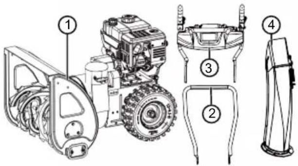
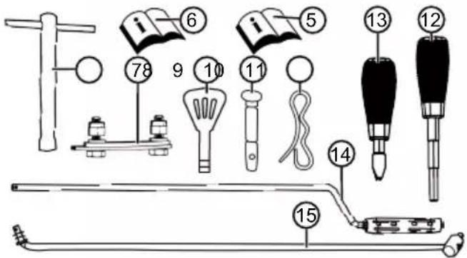
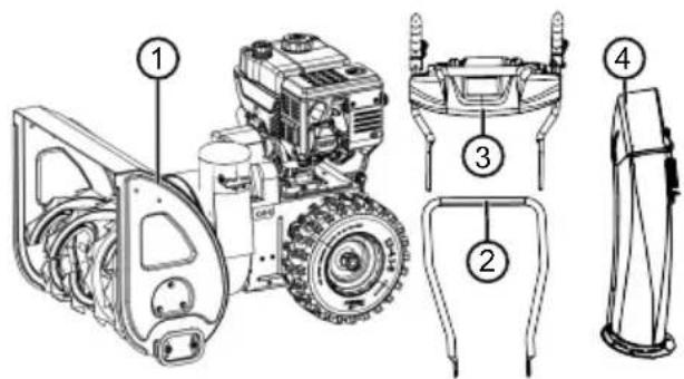
The items listed here are included in the standard scope of supply. Check that all items are present:
No. Component
| 1 Snow blower | |
| 2 Lower brace | |
| 3 Operating panel with upper brace | |
| 4 Snow discharge spout | |
| 5 Operating instructions for the snow blower | |
| 6 Operating instructions for the engine | |
| Bag with: | |
| 7 | ■ Attachment kit for snow discharge spout (x3) |
| 8 | ■ Spark plug spanner |
| 9 | ■ Engine key (x2) |
| 10 | ■ Spare shear pins (x4) |
| Bag with: | |
| 11 | ■ Cotter pins (x4) |
| 12 | ■ Lever for discharge height with spring lock washer |
| 13 | ■ Lever for gear selection with spring lock washer |
No. Component
14 Rod for gear selector lever
15 Hand crank for snow discharge spout adjustment
2.5 Symbols on the appliance
2.5.1 Safety signs
Symbol Meaning

Important! Pay special attention when handling this product!
Read the operating instructions before starting operation!
Keep away from the discharge area. Danger from discharged snow.

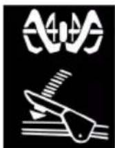
Wear safety goggles and ear protectors!
Do not reach into rotating parts. Risk of entanglement!
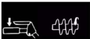
Do not reach into the snow discharge spout!
Do not reach or step into the transport auger!

Switch off the engine before starting any work on the appliance.
Remove the spark plug connector before maintenance and repair work.
Symbol Meaning
Keep other people out of the danger area!
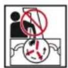
Rotating parts in the discharge area! Risk of entanglement!
2.5.2 Operating signs
Symbol Meaning
Choke
CLOSE / OPEN

Throttle
Slow / Fast

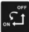
Engine key
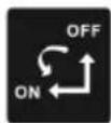
On/Off

Fuel cock
OFF (closed)
ON (open)
Primer button

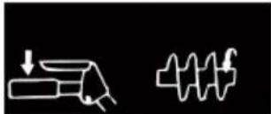
Auger drive
Start / stop

Symbol Meaning
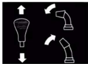
Travel drive
Start / stop
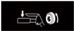
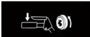
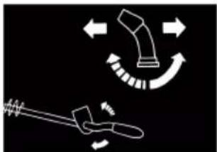
Align snow discharge spout with crank

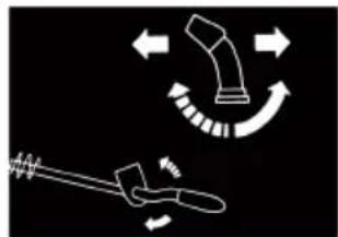
Adjust snow discharge height with lever
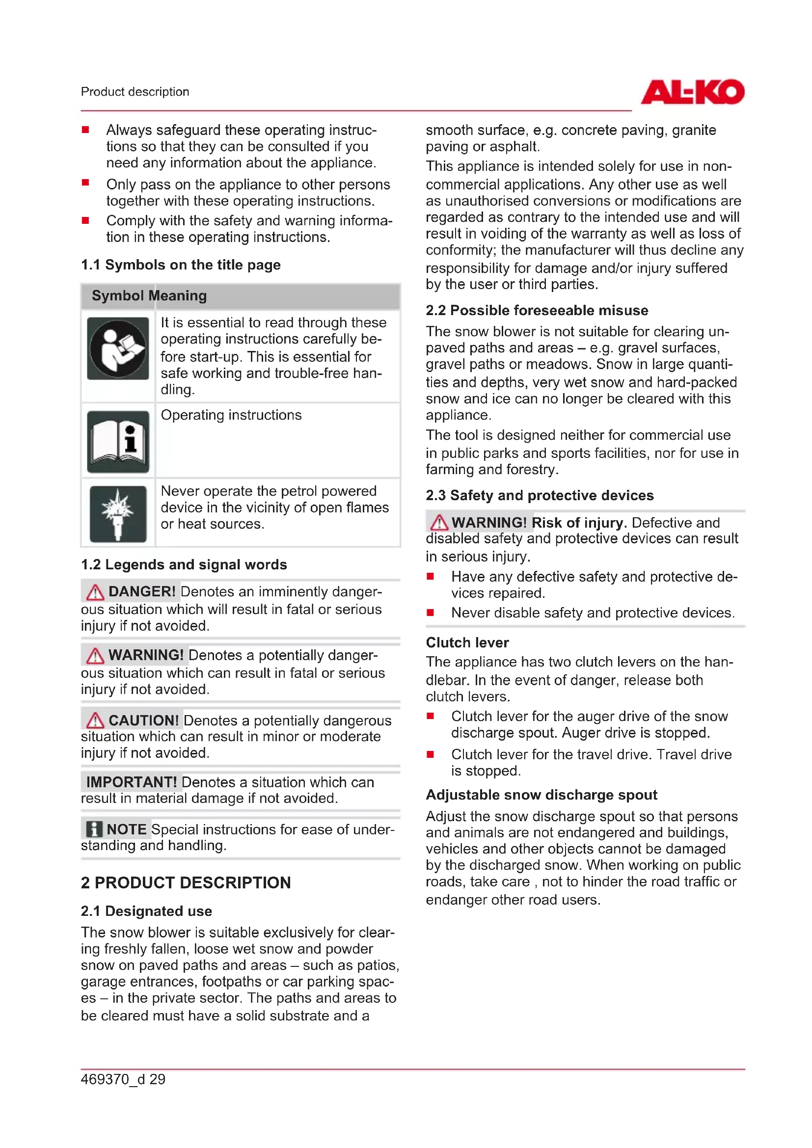
2.6 Product overview - 620 E III (01)
The product overview (01) gives an overview of the appliance.
No. Component
1 Heated handles
2 Light switch
3 Handle heater switch
4 Spare shear pins
5 Clutch lever for the auger drive
6 Lever for adjustment of the discharge height
7 Gear selector lever, 6 forward and 2 reverse gears
8 Clutch lever for the travel drive
9 Deflector on snow discharge spout for setting the discharge height
No. Component
10 Snow discharge spout with guard
11 Lights
12 Hand crank for adjusting the discharge direction
13 Tank cap
14 Oil filler cap
15 Plough
16 Cleaning tool (attached to the plough)
17 Spark plug connector
18 Transport auger
19 Discharge wheel
20 Clearing plate
21 Height-adjustable skids
3 SAFETY INSTRUCTIONS
DANGER! Danger of fatal injury and danger of extremely severe injury! Lack of knowledge of the safety instructions and operating instructions can lead to extremely serious and even fatal injury.
Observe all safety instructions and instructions for use in these operating instructions as well the operating instructions which are referred to before you start using the appliance.
- Keep all supplied documents in a safe place for future reference.
WARNING! Danger of explosion and fire.
Escaping fuel creates an explosive petrol/air mixture. Deflagration, explosion and fire can lead to serious and even fatal injuries if fuel is not handled properly.
Never store the engine in front of naked flames or heat sources.
Never operate the engine in a flammable environment.
WARNING! Danger of injury from faulty appliance. Operation of an faulty appliance can result in serious injury and damage to the appliance.
- Operate the appliance only when it is undamaged and has not defects, and when no parts are missing or loose.
WARNING! Danger from rotating appliance parts! Reaching into rotating appliance parts will result in serious injuries!
Never reach into the rotating transport auger!
WARNING! Risk of injury. Defective and disabled safety and protective devices can result in serious injury.
Have any defective safety and protective devices repaired.
Never disable safety and protective devices.
3.1 Safety instructions in accordance with ISO 8437, Annex A
Getting to know the appliance
- Read the operating and maintenance instructions through carefully. Familiarise yourself thoroughly with the control elements and the proper use of the appliance. Learn to quickly stop the appliance and switch off the control elements.
- Children must not be allowed to operate the appliance under any circumstances. Adults who have not been properly instructed must not be allowed to operate the appliance under any circumstances.
- Keep persons, in particular small children, and pets out of the working area.
- Walk carefully, particularly when working backwards, to avoid slipping or falling.
Preparation
- Carefully check the area in which the appliance is to be used and remove all door mats, sledges, boards, cables and other objects.
- Disengage the clutch completely and shift to neutral before starting the engine.
- Do not operate the appliance without adequate winter clothing. Wear shoes that ensure a good grip on slippery ground.
- Take care when handling petrol; it is highly inflammable.
Use a proper petrol canister.
- Never refuel when the engine is running or hot.
Always fill the fuel tank outdoors and taking the greatest care. Never fill the fuel tank in closed rooms.
Fit the fuel tank cap tightly and wipe up any spilled petrol.
- Use an earthed plug socket for all appliances with electric drive or electric ignition.
- Adjust the height of the header casing when clearing gravel or stony surfaces.
- Never try to make changes to settings with the engine running (except where expressly recommended by the manufacturer).
- Allow the engine and appliance to cool to the outside temperature before starting to clear snow.
- Operation of any powered machine can result in foreign objects being projected into the eyes. Therefore always wear safety goggles or eye protection during operation, adjustment or repair.
- Wear ear protectors to prevent hearing damage.
Operation
- Keep hands and feet away from all moving parts, including under the appliance. Keep away from the discharge opening at all times.
- Work particularly carefully when operating the appliance on gravel drives, paths or roads, or when crossing such. Always pay attention to hidden obstacles or road traffic.
- Should you collide with a foreign object, switch off the engine, remove the spark plug cable connector, inspect the snow blower carefully for damage and repair the damage before starting the engine and operating the snow blower again.
- If the appliance vibrates abnormally, switch off the engine and immediately locate the cause. Vibrations are generally a sign that there is a problem.
- Always switch off the engine when you stop work, before cleaning the header/drive wheel casing or the discharge chute, and when carrying out repairs, settings or inspections.
- Before carrying out cleaning, repairs or inspections, always ensure that the header/ drive wheel and all moving parts are at a standstill. Disconnect the spark plug cable and keep it away from the spark plug to avoid accidental ignition. In the case of electric motors, disconnect the mains plug.
-
Never operate the engine in closed rooms except when starting or when moving the snow blower into or out of a building. Keep the doors open when doing so; exhaust gases are toxic.
-
Do not use the appliance on slopes. Be very careful when turning on sloping ground. Do not try to clear steep slopes.
- Never operate the snow blower without the proper guards, safety plates or other protective equipment.
- Never use the snow blower in the vicinity of windows, motor vehicles, light wells, sloping ground, etc. without adjusting the snow discharge direction accordingly. Keep children and pets away from the working area.
- Do not overload the machine by trying to clear snow too fast.
- Never use the machine at high transport speeds on slippery ground. Take care when working backwards.
- Never direct the snow discharge towards bystanders and do not allow persons to walk in front of the appliance.
- Disconnect the power supply to the header/ drive wheel when the snow blower is being transported or is not in use.
- Use only attachments and accessories approved by the manufacturer of the snow blower, e.g. balancing weights, counterweights, casings, etc.
- Never operate the snow blower in poor visibility or with poor lighting. Always ensure a secure footing and hold the handles firmly. Only walk and never run when operating the appliance.
Maintenance and storage
WARNING! Serious hand injuries when cleaning the blocked discharge channel!
Touching the rotating paddle wheel in the discharge channel results in serious hand injuries. These are the most common injuries on the snow blower. To clean the discharge channel:
Switch off the snow blower!
Wait around 10 s until the paddle wheel stops.
Always use a suitable tool to clean the discharge channel.
Never use your hands to clean the discharge channel!
-
Check regularly that the guards, the knife bolts, the engine mounting bolts, etc. are securely tightened in order to ensure safe operation of the appliance.
-
Never store the appliance in a building where there are sources of ignition, such as water heaters, electric fan heaters, clothes dryers, etc., as long as there is petrol in the tank. Allow the engine to cool down before storing the appliance in a closed room.
- Always observe the precise instructions in the operating instructions if the snow blower is to be placed into storage for a prolonged period.
- Leave all safety and operating instruction signs on the appliance, and renew them, if necessary.
- Allow the appliance to run for a few minutes after finishing snow clearing to prevent freezing of the header/drive wheel.
3.2 Safety instructions relating to operation
Use the appliance only for the purposes for which it is intended. Any non-intended use can lead to injury and property damage.
- Never operate the appliance with worn or defective parts. Always replace defective parts with original spare parts from the manufacturer. If the appliance is operated with worn or defective parts, guarantee claims against the manufacturer are excluded.
In the following cases, switch off the engine, wait for the appliance to come to a standstill and disconnect the spark plug connector:
When leaving the machine
During cleaning and maintenance work
Before starting adjustment work
In the event of malfunctions
Before clearing blockages
Before unclogging
After contact with foreign objects
If malfunctions and unusual vibrations occur in the appliance
- Do not operate the appliance if you are under the influence of alcohol, drugs or medication.
Wear clothing and protective equipment in accordance with the regulations in order to avoid injury to the head and limbs as well as to avoid hearing impairment.
The clothing must be appropriate (tightly fitting) and must not restrict movements. Never wear loose items of clothing or accessories that could be drawn into the appliance, e.g. scarves.
The personal protective equipment comprises:
Hearing protection and protective eyewear
Sturdy, non-slip shoes
Protective gloves
- Keep hands, feet, other limbs and clothing away from the rotating clearing paddle, transport auger and discharge wheel.
Observe the local working time regulations in force. - Do not leave the operational appliance unsupervised.
Never clear snow from roofs.
3.3 Handling of petrol and oil
Risk of explosion and fire:
An escaping petrol/air mixture can cause an explosive atmosphere. Deflagration, explosion and fire can lead to serious and even fatal injuries if fuel is not handled properly. Observe the following:
Do not smoke when dealing with petrol.
Only handle petrol out of doors and never in enclosed spaces.
It is essential to heed the code of conduct stated below.
Only transport and store petrol and oil in containers approved for that purpose. Ensure that children have no access to stored petrol and oil.
In order to avoid ground contamination (environmental protection) when filling, ensure that no petrol or oil enters the soil. Use a funnel for filling.
- Never fill the appliance in enclosed spaces. Petrol vapours may gather at ground level, and thereby result in a deflagration or even an explosion.
- Immediately wipe any spilled petrol off the appliance and the ground. Allow textiles used to wipe off petrol to dry in a well ventilated place before disposing of them. Otherwise, sudden self-ignition may occur.
If petrol has been spilled, petrol vapours occur. For this reason, do not start the engine at the same location and move it at least 3 m away.
Avoid skin contact with mineral oil products. Do not inhale petrol vapours. When filling, al
ways wear protective gloves. Change and clean protective clothing regularly.
- Ensure that your clothing does not come into contact with petrol. If petrol has got onto your clothing, change it immediately.
- Never open the fuel tank cap while the engine is running or hot.
Never fill the fuel tank while the engine is running or hot.
Never over-fill the fuel tank (petrol expands).
Always screw on the fuel tank cap tightly. - Replace a damaged fuel tank or fuel tank cap.
- Never eat, drink or smoke when filling the appliance with petrol or oil.
If petrol has leaked out:
Do not start the engine.
Avoid start attempts.
Pick up leaked petrol using a binding agent or cloth and dispose of in the proper manner.
Clean the appliance.
If engine oil has leaked out:
Do not start the engine.
Pick up leaked oil using an oil binding agent or cloth and dispose of in the proper manner.
Clean the appliance.
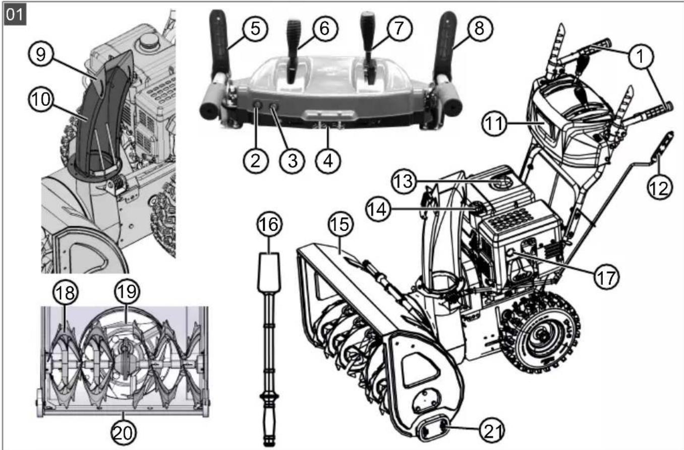
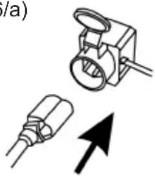
4 UNPACKING APPLIANCE (02)
WARNING! Danger of crushing if the machine tips over! The appliance is heavy! If it tips over, limbs can be crushed and persons can be seriously injured.
At least two persons are required for unpacking the appliance!
Avoid tipping the appliance!
The appliance is supplied with all accessory parts in a cardboard box. The box is located on a euro pallet.
- Place the box on a level horizontal surface.
- Remove the packing straps.
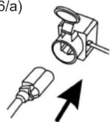
- Open the box at the top (02/a).
- Remove the packaging material.
-
Carefully remove loose parts, bag with small parts and operating instructions.
-
Use a knife to carefully cut open the rear wall of the box (i.e. where the engine is located) so that the appliance is not damaged.
- Fold down the rear wall of the box (02/b).
- Carefully remove the other loose parts and other packaging material.
- Roll the snow blower backwards, i.e. with the engine at the front, out of the box (02/c).
5 ASSEMBLY
WARNING! Danger if assembly is not carried out completely! Use of an incompletely assembled device can result in serious injury.
Only use the device when it is fully assembled!
Before switching on, check that all safety and protective devices are in place and functioning correctly!
Necessary tools
| No. Tool |
| 1 Open-end or ring spanner WAF 10 (x2) |
| 2 Open-end or ring spanner WAF 13 |
| 3 5 mm Allen key |
| 4 Combination or long-nose pliers |
| 5 Screwdriver |
| 6 Spray oil |
| 7 Tyre pump with pressure gauge (car tyre valve) |
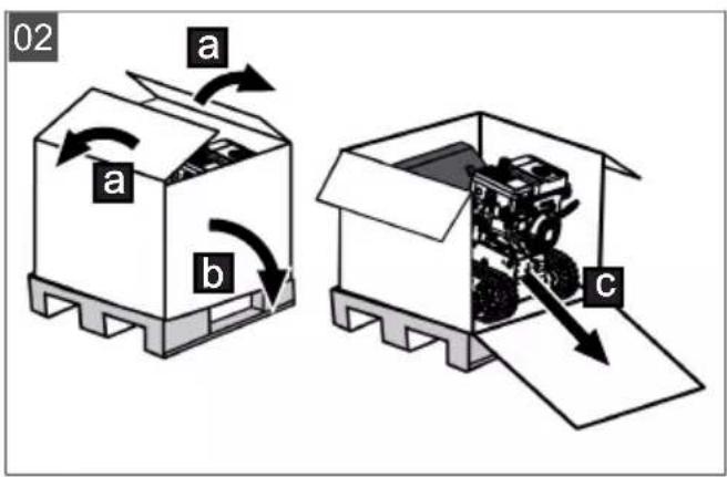
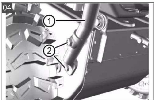
5.1 Fitting the lower brace (03, 04)
Mount the lower brace on the left and right at the bottom of the snow blower.
- Undo the screws (03/1).
- Attach the lower brace (04/1).
- Insert the bolts (04/2) through the lower brace and tighten.
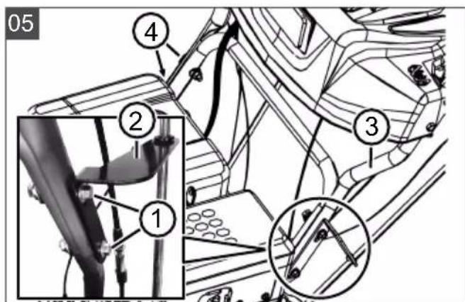
5.2 Fitting the operating panel (05)
- Left lower brace: Unfasten 2 bolts (05/1) on the mounting bracket (05/2) and remove the mounting bracket.
- Attach upper brace (05/3) with control panel.
-
Right upper brace: Insert 2 bolts (05/4) through the upper brace and lower brace and tighten with washers and nuts.
-
Left upper brace: Insert 2 bolts (05/1) through upper brace, lower brace and mounting bracket and tighten slightly with washers and nuts.
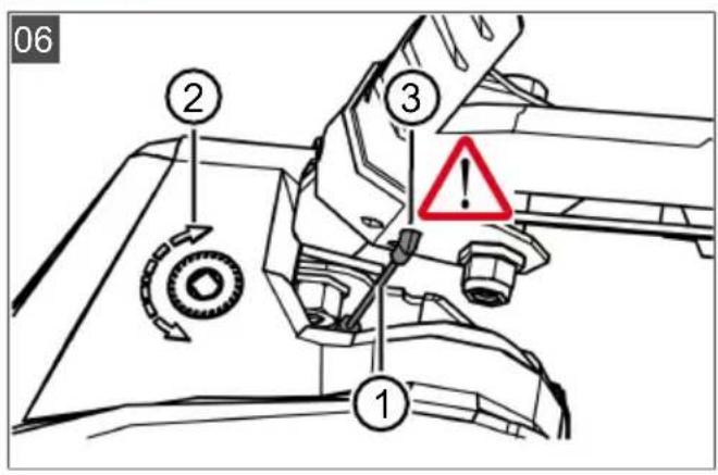
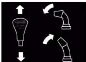
5.3 Installing and adjusting Bowden cables for travel and worm drives (06 - 11)
- Attach the Bowden cable (06/1) for the travel drive (06/2) into the lower hole (06/3) of the right-hand lever.
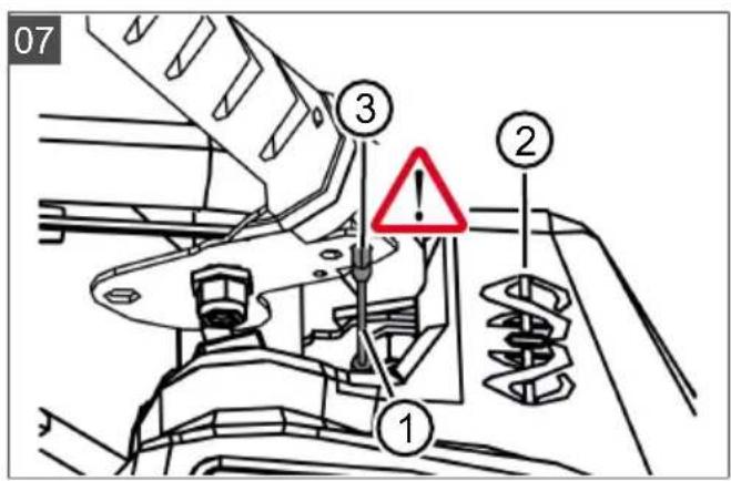
-
Attach the Bowden cable (07/1) for the worm drive (07/2) into the upper hole (07/3) of the left-hand lever.
-
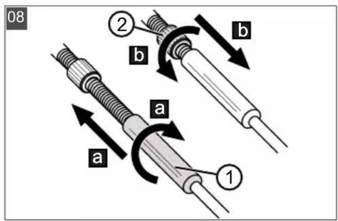
Adjust the Bowden cables as follows:
Turn the adjuster on the Bowden cable (08/1) in the direction of the arrow (08/a) until the Bowden cable no longer sags (is slightly tensioned). While turning the adjuster, hold the cable so that it does not become twisted.
- Tighten lock nut (08/2) (08/b).
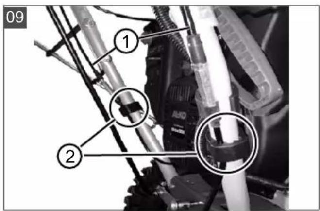
- Fix the Bowden cables (09/1) with the clamps (09/2) on the left and right of the handlebar.
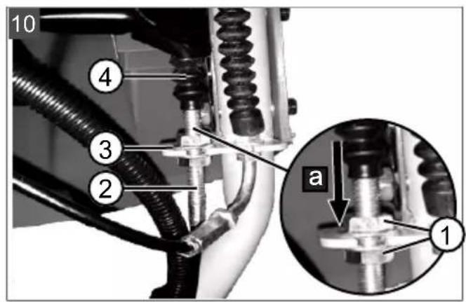
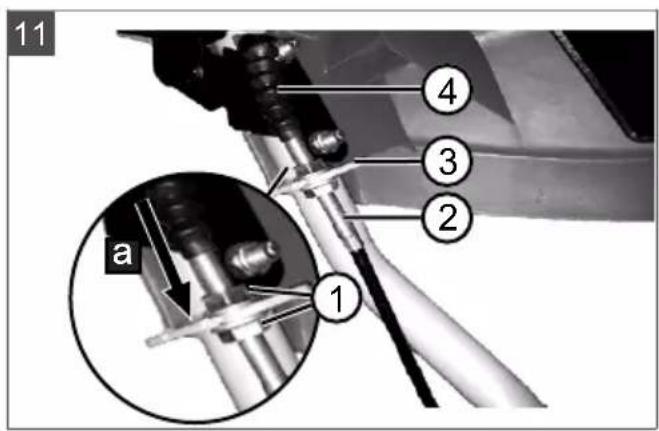
- Tension the Bowden cable:
Loosely tighten the lock nuts (10/1, 11/1).
Turn the threaded end piece (10/2, 11/2) upwards until the Bowden cable is tensioned.
Turn the lock nuts against the guide (10/3, 11/3) to fix the Bowden cable.
- Pull down the rubber sheath (10/4, 11/4) to the lock nut (10/a, 11/a) to protect the Bowden cable against corrosion.
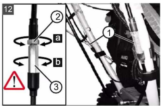
5.4 Adjusting the Bowden cable (12)
The fine adjustment is carried out via the adjusting screw.
- Loosen the lock nut (12/2) on the adjusting screw (12/a).
- Turn the adjusting screw (12/3) (12/b) to lengthen or shorten the path of the Bowden cable. Ensure that the Bowden cable is slightly taut and is not sagging.
- Re-tighten the lock nut (12/2) (12/a).
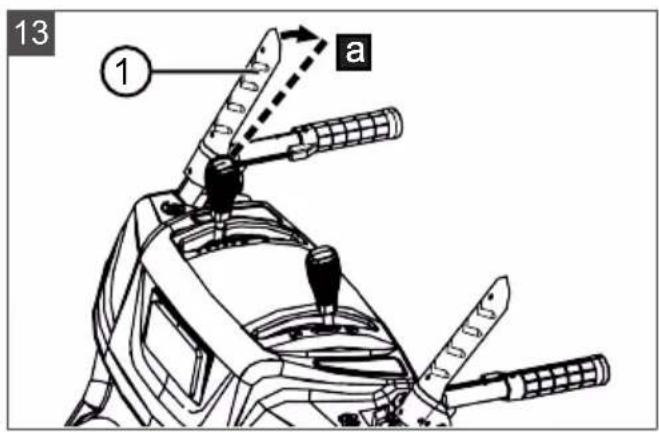
5.5 Checking the Bowden cable setting (13)
The Bowden cable of the travel drive lengthens over time. If the travel drive can no longer be switched on while the engine is running, the Bowden cable has become too long and must be tightened.
- Switch off the appliance (see chapter 6.8 "Stopping the engine (37, 38)", page 39).
- Re-adjusting the Bowden cable (see chapter 5.3 "Installing and adjusting Bowden cables for travel and worm drives (06 - 11)", page 36).
To check the Bowden cable setting:
- Start the engine (see chapter 6.7 "Starting the engine (31 - 36)", page 38).
-
Put into gear (see chapter 7.1 "Starting clearing (39 - 41)", page 39).
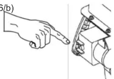
-
Slowly push the right handle (13/1) downwards (13/a) until a slight resistance is felt. The pressure point of the clutch has been determined.
- If the travel drive is not switched on: Repeat the previous steps.
- If adjusting the Bowden cable is not successful: Contact one of the manufacturer's service centres.
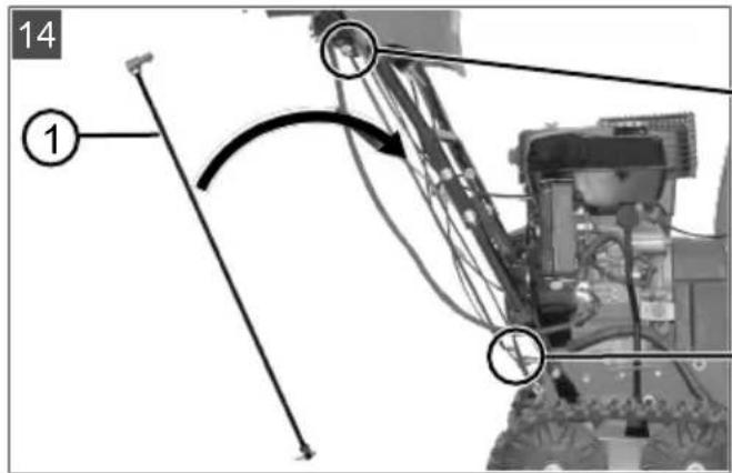
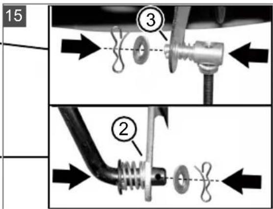
5.6 Mounting the rod for the gear selector lever (14, 15)
- Attach the rod (14/1) at the bottom into the gear shift mount (15/2).
- Attach the rod on the top of the gear selector lever (15/3) in the mount.
- Secure the rod at the top and bottom with washers and cotter pins.
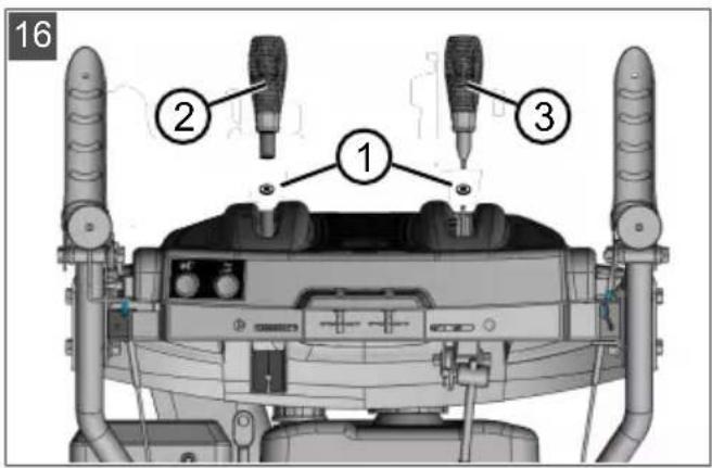
5.7 Fitting the levers for gear selection and discharge height (16)
- Fit spring washers (16/1) onto the thread.
- Screw on and tighten the discharge height lever (16/2).
- Screw on and tighten the gear selection lever (16/3).
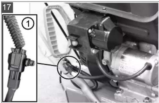
5.8 Plugging in the heater and lighting plug (17)
- Connect the plug parts (17/1) for the heater and lighting.
- Secure the plug connection.
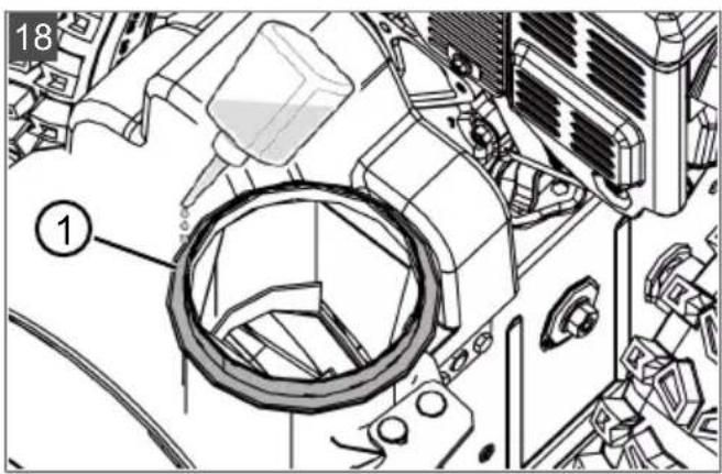
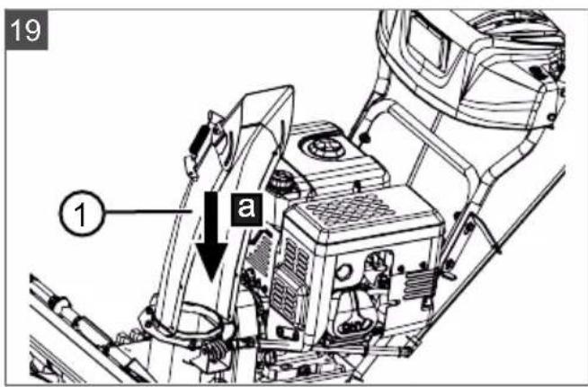
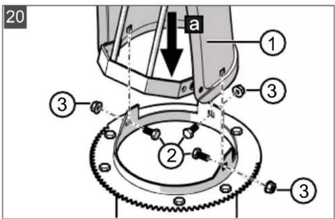
5.9 Fitting the snow discharge spout (18-21)
- Apply spray oil (or grease) to the sliding surface (18/1) of the snow discharge spout on the snow blower.
-
Fit the snow discharge spout (19/1) (19/a, 20/a).
-
Insert the mounting bolts (20/2) through the brackets and snow discharge spout from the inside.
- Secure the snow discharge spout with the self-locking nuts (20/3).
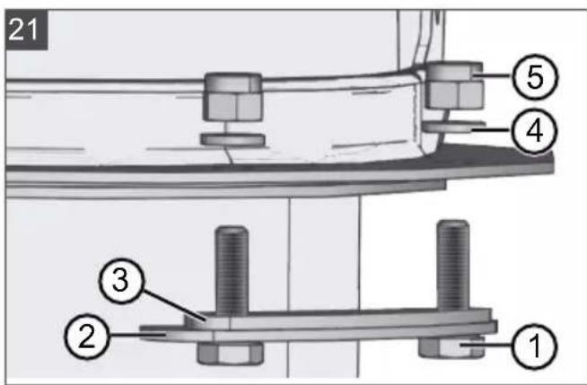
- Insert the mounting bolts (21/1) through the large guide plate (21/2) and fit the small guide plate (21/3). Note: The small guide plate must lie on top of the large guide plate.
- Insert the guide plates with the mounting bolts from below into the snow discharge spout.
- Fit washers (21/4) onto the bolts.
- Securely tighten the self-locking nuts (21/5).
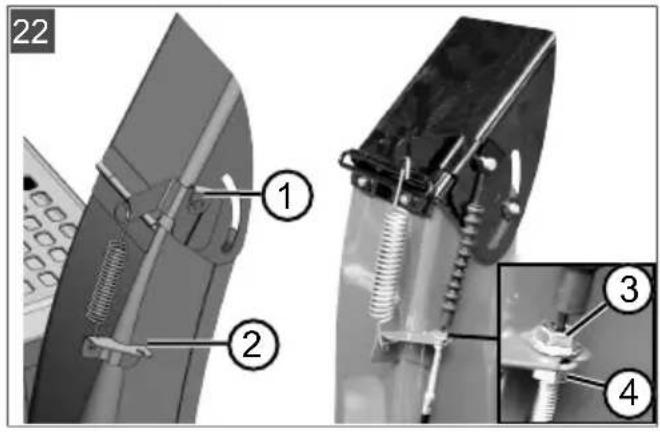
5.10 Connecting the Bowden cable to the discharge flap (22)
This Bowden cable moves the discharge flap of the snow discharge spout and serves to set the discharge height.
- Hook the Bowden cable into the guides (22/1, 22/2). The rubber sheath must be attached to the outer Bowden cable.
- Turn the lock nut (22/3, 22/4) firmly against the guide (22/2) until the Bowden cable is tensioned.
-
Use the lever for setting the discharge height to check the length of the Bowden cable:
-
Move the lever all the way to the front. The discharge flap must move all the way down.
- Move the lever all the way to the rear. The discharge flap must move all the way up.
If necessary, change the length of the Bowden cable.
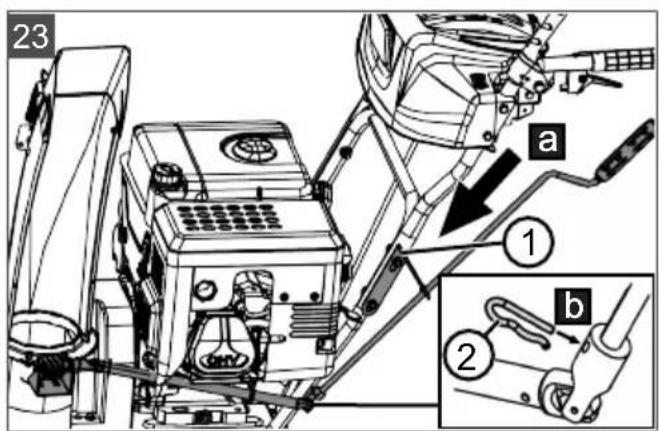
5.11 Fitting the snow discharge spout hand crank (23)
- Push the hand crank through the guide (23/1) in the handlebar (23/a).
Note: If the connecting rod cannot be moved to the lower guide or can only be moved with difficulty, loosen the upper guide and tighten it again after installing the connecting rod.
- Insert the cotter pin (23/2) (23/b).
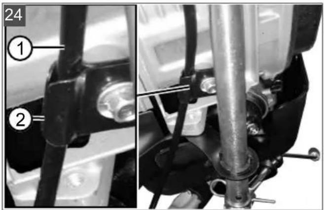
5.12 Attaching the Bowden cable (24)
- Attach the Bowden cable (24/1) into the mount (24/2) under the engine.
6 START-UP
WARNING! Danger of injury from faulty appliance. Operation of an faulty appliance can result in serious injury and damage to the appliance.
- Operate the appliance only when it is undamaged and has not defects, and when no parts are missing or loose.
NOTE Always perform a visual check prior to start-up. Do not operate the equipment if the operating and/or fastening parts are loose, damaged, or worn.
6.1 Operating material
DANGER! Risk of explosion and fire. An escaping petrol/air mixture can cause an explosive atmosphere. Deflagation, explosion and fire can lead to serious and even fatal injuries if fuel is not handled properly.
Do not smoke when dealing with petrol.
Only handle petrol out of doors and never in enclosed spaces.
DANGER! Risk of poisoning. The engine exhaust gases contain carbon monoxide that can kill a person within a few minutes.
Operate the engine only outdoors, never in a closed room.
Do not inhale the engine exhaust gases.
- Switch off the engine if you feel nauseous, dizzy or weak during use. Immediately consult a doctor.
NOTE Dispose of used engine oil in an environmentally responsible manner! We recommend disposing of waste oil in a closed container at a recycling centre or customer service centre. Do not dispose of waste oil:
In domestic waste
In sewers or drains
In the ground
NOTE Observe the enclosed operating instructions for the engine!
Before starting operation, the engine must be filled with oil and the snow blower filled with petrol.
For information on petrol and engine oil: see technical data.
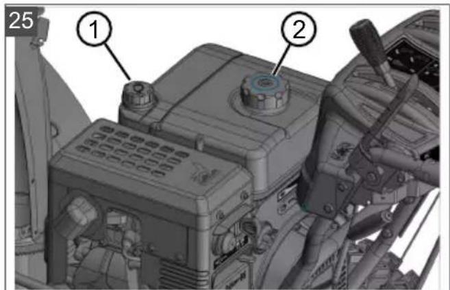
6.2 Filling with engine oil (25)
- Unscrew the oil filler cap (25/1) and put it down in a clean place.
- Pour in oil through a funnel.
- Check the fill level with an oil dipstick, see engine operating manual.
- Securely tighten and clean the oil filler neck.
6.3 Filling with petrol (25)
- Unscrew the tank cap (25/2) and put it down in a clean place.
- Pour in petrol through a funnel.
- Securely tighten the fuel filler cap and clean the tank filler neck.
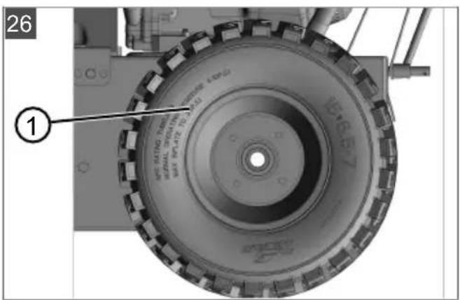
6.4 Checking the tyre pressure (26)
- Check the tyre pressure particularly before using for the first time in the winter and at least every three months during the season. The maximum permissible tyre pressure is indicated on the tyres (26/1). Note: Note: 1 bar = approx. 14.5 psi
- Pump up both tyres. Both tyres must have the same pressure.
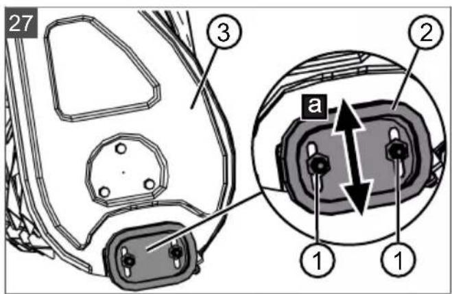
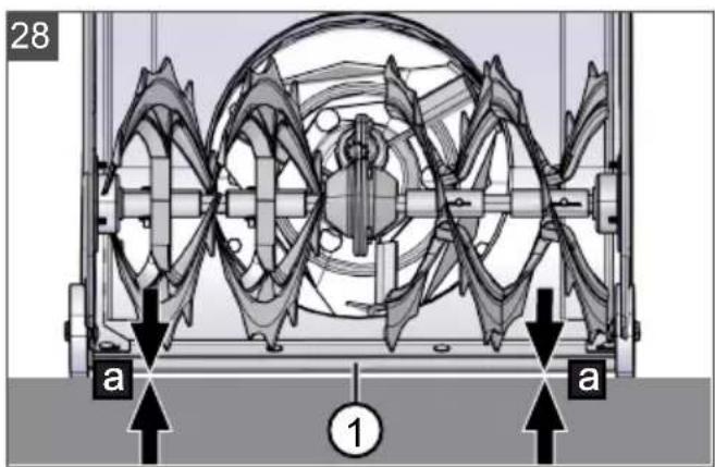
6.5 Adjusting the clearing height (27 - 29)
CAUTION! Risk of injury. Risk of cuts when reaching into the running transport auger.
Adjust the clearing height only with the engine switched off and the transport auger at standstill.
Adjust the clearing height so that no gravel or other foreign matter can be picked up. Give consideration to very uneven ground, for example tyre tracks, and to manhole covers or paving stones.
- Move the appliance to level ground for adjustment.
- Unfasten the clamping screws (27/1) of the skids (27/2) on the left and right of the plough (27/3).
- Push the skids up or down (27/a) to raise the clearing plate (28/1) to the desired height.
- Tighten the clamping screws of the skids.
- Ensure that both skids are at the same height so that the clearing plate runs parallel to the ground (28/a).
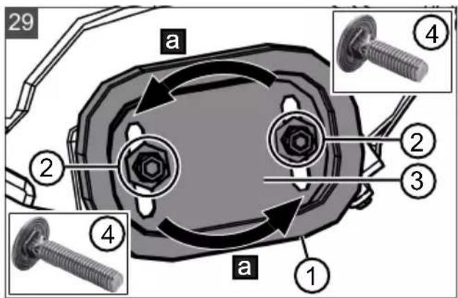
Skids worn (29)
If the wear edge (29/1) of the skids is worn down, turn it 180^ to use the second side.
- Unscrew the nuts (29/2) including the washers.
- Remove the metal plate (29/3).
- Turn the skid by 180^ (29/a).
- Fit washers and tighten nuts. Note: Be careful not to swap the clamping screws (29/4) because they are of different lengths.
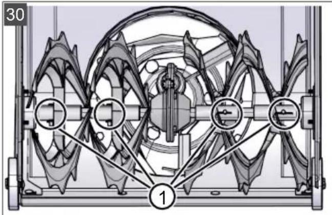
6.6 Checking the shear pins on the appliance (30, 46)
IMPORTANT! Danger of damage to the appliance. A frozen auger gearbox can result in damage to the V-belt.
Check whether the auger gearbox is frozen before starting the engine.
Park the snow blower in a suitable place to allow the auger gearbox to thaw, if necessary.
-
Before every start, check that the shear pins (30/1, 46/2) are undamaged.
-
Replace broken shear pins with OEM spare parts (see chapter 9.4 "Replacing the shear pins (30, 46)", page 41). Use of non-approved spare parts can result in serious damage to the appliance!
Two spare shear pins (01/4) can be found on the operating panel. -
Inspect all operating elements, safety devices, nuts, bolts and studs of the device for completeness, tightness and sound condition.
6.7 Starting the engine (31-36)
DANGER! Risk of poisoning. The engine exhaust gases contain carbon monoxide that can kill a person within a few minutes.
Operate the engine only outdoors, never in a closed room.
Do not inhale the engine exhaust gases.
- Switch off the engine if you feel nauseous, dizzy or weak during use. Immediately consult a doctor.
IMPORTANT! Danger of damage to the appliance. A frozen auger gearbox can result in damage to the V-belt.
Check whether the auger gearbox is frozen before starting the engine.
- Park the snow blower in a suitable place to allow the auger gearbox to thaw, if necessary.
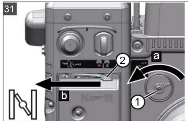
Starting process (31 - 34)
- Check the oil and fuel level.
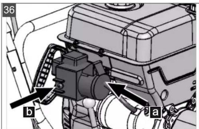
- Open fuel cock (31/1) (31/a).
- Check that travel drive and auger drive are disengaged. Both clutch levers must be in the upright position.
- Move choke (31/2) to the "CLOSED" position (31/b).
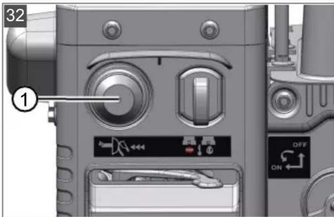
- Press primer button (32/1) 3x at intervals of approx. 2 seconds. At temperatures below 10 ^ C , press the primer button 5x.
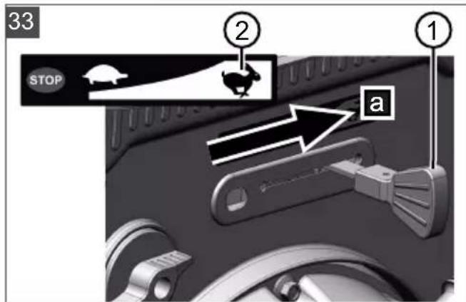
- Move throttle lever (33/1) to the Fast position (hare) (33/a).
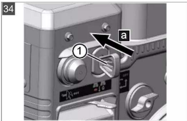
- Insert engine key (34/1).
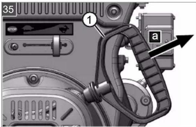
Manual start (35)
- Pull the starter cable (35/1) out slightly (35/a) until initial resistance is felt, then pull out sharply and allow it to wind back in slowly.
230 V starting process (36)
- (36/a)
- (36,b)
6.8 Stopping the engine (37, 38)
WARNING! Danger from rotating appliance parts! Reaching into rotating appliance parts will result in serious injuries!
Never reach into the rotating transport auger!
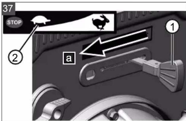
- Move the throttle lever (37/1) to the "Slow" position (Tortoise) (37/a).
- To prevent freezing, allow transport auger and discharge wheel to continue to run until they are more or less free of snow. The V-belts could otherwise be damaged during starting.
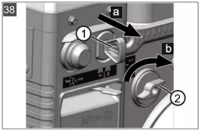
- Remove engine key (38/1) (38/a).
- The engine stops.
- Turn fuel cock (38/2) to the "OFF" (closed) position (38/b).
7 OPERATION
7.1 Starting clearing (39 - 41)
WARNING! Danger from rotating appliance parts! Reaching into rotating appliance parts will result in serious injuries!
Never reach into the rotating transport auger!
WARNING! Objects being discharged!
Risk of injury and risk of material damage due to objects being discharged!
-
Never turn the discharge channel in the direction of persons, animals, windows, cars or doors.
-
Start clearing.
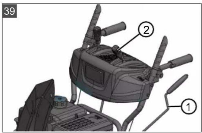
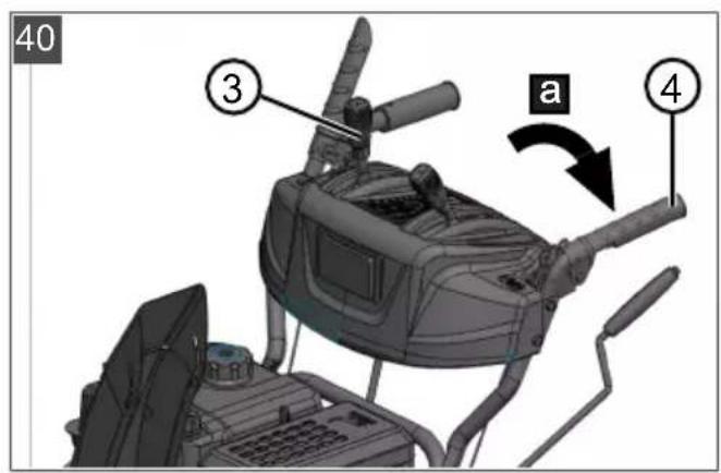
- Check the position of the snow discharge spout and adjust the discharge direction using the hand crank (39/1).
- Adjust the discharge height (39/2).
- Start the engine (see chapter 6.7 "Starting the engine (31 - 36)", page 38).
- Engage the gear for the travel drive (40/3):
1 to 6 are forward gears, with 1 the lowest and 6 the highest gear.
R1 and R2 are reverse gears, with R1 the lower and R2 the higher gear.
- Push clutch lever (40/4) for the auger drive (40/a).
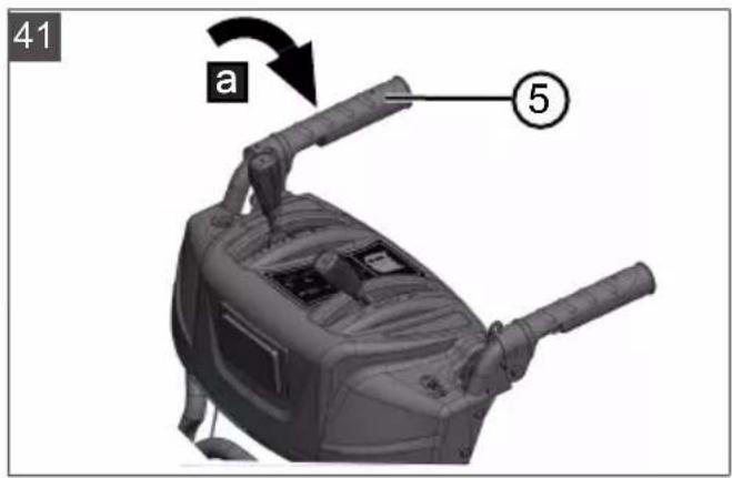
- Push clutch lever (41/5) for the travel drive (41/a).
7.2 Stopping clearing (42)
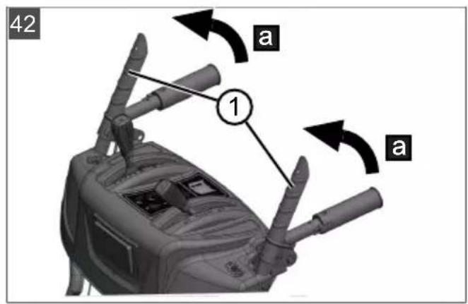
- Release the clutch lever (42/1) to disengage the auger drive and travel drive (42/a).
To prevent freezing, allow transport auger and discharge wheel to continue to run until they are more or less free of snow. A frozen transport auger would damage the V-belts.
The snow blower comes to a standstill, transport auger and discharge wheel stop.
7.3 Changing gear for the travel drive (41 - 43)
IMPORTANT! Risk of damage to the appliance. The transmission is damaged if the clutch is not disengaged before the gear change.
First disengage the clutch, then change gears.
- Release clutch lever for the travel drive (42/1), i.e. disengage (42/a).
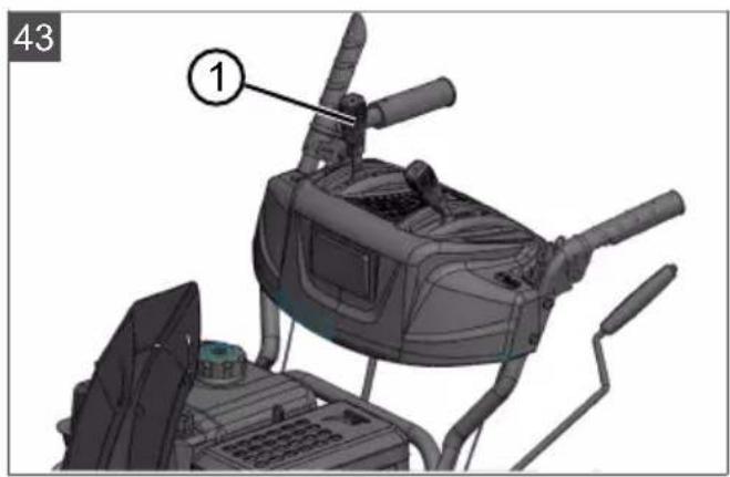
Note: The transport auger blocks when it is stopped in wet and heavy snow and then restarted. Do not release the clutch lever for the auger drive! - Change gear with gear lever (43/1).
- Push clutch lever (41/5) for the travel drive (41/a).
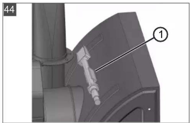
7.4 Clearing clogging in the snow discharge spout (42, 44)
NOTE Allow the transport auger to run at all times, if possible, in order to avoid clogging in heavy and wet snow.
If the snow is no longer discharged correctly, snow and ice deposits on the transport augers and in the discharge channel may be the cause.
- Release the clutch lever (42/1) to disengage the auger drive and travel drive (42/a).
- Switch off the engine (see chapter 6.8 "Stopping the engine (37, 38)", page 39).
- Carefully clear the snow from the discharge channel and transport auger using the cleaning tool (44/1).
If the snow discharge is still unsatisfactory, take the appliance to a specialist workshop.
8 REPAIR
WARNING! Risk of injury during repair
work. Improper repairs can lead to serious injuries and damage to the appliance.
Have repair work performed by the manufacturer's service centres and authorised specialist companies only!
A professional inspection is always required:
After colliding with an obstacle.
If the engine stops suddenly.
If the transport auger or discharge wheel are damaged.
9 MAINTENANCE AND CARE
CAUTION! Risk of injury. Sharp-edged
and moving appliance parts can lead to injury.
Always wear protective gloves during maintenance, care and cleaning work!
- Switch off the engine and check that the engine is at a standstill!
Remove the spark plug connector!
Clean the appliance after every use. In particular, remove any residues of road salt.
- Do not spray the appliance with water. Penetrating water can lead to malfunctions (ignition system, carburettor).
Always replace a defective silencer.
Observe the maintenance schedule.
Observe the engine operating manual.
9.1 Maintenance schedule
Before every use
Check the oil level (see engine operating manual).
Check the shear pins.
Inspect the appliance for damage.
Check whether the transport auger is frozen.
After the first 5 operating hours
- Change the engine oil (see engine operating manual).
Every 8 operating hours
Grease the transport auger.
Every 3 months
Check the tyre pressure.
Oil the ring of the snow discharge spout with spray oil.
Once a year
- Replace the spark plug (see engine operating manual).
Grease the transport auger.
Change the engine oil.
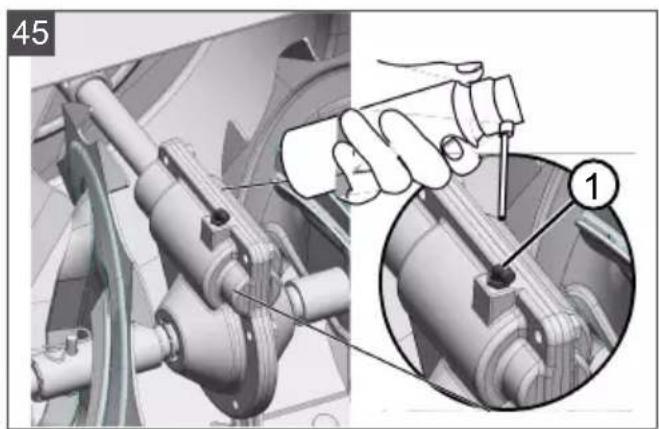
9.2 Greasing the transport auger (45)
Pump approx. 2-3 strokes of multi-purpose grease into grease nipple (45/1) using a grease gun.
9.3 Servicing the travel and auger drives (08)
WARNING! Risk of injury during maintenance work. Improper maintenance can result in serious injury and in damage to the appliance.
Adjust the Bowden cable only with the engine switched off.
- Stop the engine if the travel/auger drive cannot be switched off.
- Do not try to carry out repairs yourself and contact a specialist workshop immediately.
NOTE Moisture in the Bowden cable can result in corrosion or freezing. A damaged Bowden cable must be replaced.
Adjust Bowden cable
If the travel/auger drive cannot be engaged with the engine running, the respective Bowden cable must be adjusted.
- Loosen lock nut (08/2).
- Turn the adjuster on the Bowden cable (08/1) in the direction of the arrow (08/a) until the Bowden cable no longer sags (is slightly tensioned). While turning the adjuster, hold the cable so that it does not become twisted.
- Tighten lock nut (08/2) (08/b).
- To check the setting, start the engine and switch on the travel/auger drive.
- If the travel/auger drive still cannot be properly engaged, the appliance must be taken to a specialist workshop.
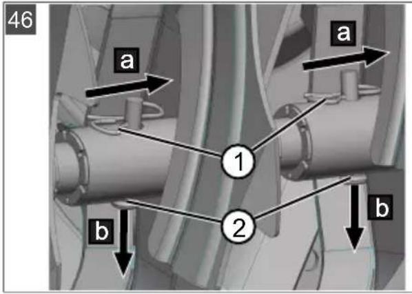
9.4 Replacing the shear pins (30, 46)
For the safety of the operator and appliance, the shear pins (30/1) can break after a blockage of the transport auger.
NOTE Replace broken shear pins with OEM spare parts. Use of non-approved spare parts can result in serious damage to the appliance!
- Switch off the appliance and remove the spark plug connector.
- Remove the cotter pin (46/1) (46/a).
- Pull out the damaged shear pins (46/2) (46/b).
- Inspect the shaft for damage.
- Insert a new shear pin and secure with cotter pin.
10 HELP IN CASE OF MALFUNCTIONS
CAUTION! Risk of injury. Sharp-edged and moving appliance parts can lead to injury.
Always wear protective gloves during maintenance, care and cleaning work!
- Switch off the engine and check that the engine is at a standstill!
Remove the spark plug connector!
NOTE For malfunctions that are not listed in this table or that you cannot resolve yourself, please contact our customer service.
| Malfunction Remedy | |
| Engine does not start. | Fill with petrol. |
| Move the throttle lever to the “Start” position. | |
| Switch on the choke and press the primer button. | |
| Service the spark plug. | |
| Engine loses power. | Clean the discharge channel/housing. |
| Clear snow and ice from the transport auger and discharge wheel. | |
| Reduce the working speed. | |
| Travel drive does not function with clutch lever pressed. | Adjust the Bowden cable. |
| Take the appliance to a Customer Service Centre. | |
| Travel drive cannot be stopped (does not disengage). | ■ Switch off the engine. ■ Do not try to repair the appliance yourself! ■ Take the appliance to a Customer Service Centre. |
| Transport auger does not rotate with clutch lever pressed. | Shear ping broken; replace the shear pin. |
| Adjust the Bowden cable. | |
Malfunction Remedy
| Take the appliance to a Customer Service Centre. | |
| Transport auger cannot be stopped (does not disengage). | Switch off the engine. Do not try to repair the appliance yourself! Take the appliance to a Customer Service Centre. |
| Abnormal appliance vibrations. | Inspect transport auger and discharge wheel. |
| Appliance pulls to one side. | Check tyre pressure and correct, if necessary. |
| Check the skids and adjust or replace, as necessary. |
Replacement parts
See: www.al-ko.com
11 STORAGE

WARNING! Danger of explosion and fire.
Petrol vapours are highly inflammable.
- Do not store the appliance close to naked flames or sources of heat.
Thoroughly clean the appliance after each use and - if present - attach all covers. Store the appliance in a dry, lockable place out of the reach of children.
If the appliance is to be stored for a prolonged period, such as after the winter, the following operations are necessary to prevent damage:
Draining the carburettor:
Start the engine.
Close the fuel cock.
Wait until the engine stops.
- Allow the engine to cool down.
Store the appliance in a dry place out of the reach of children and unauthorised persons.
Empty the fuel tank or fill it completely.
Remove the engine key.
Remove the spark plug connector.
12 DISPOSAL

Petrol and motor oil do not belong in household waste or the public sewer system, but should be collected and disposed of separately.
Before disposing of the device you must empty the fuel tank and the engine oil tank!
Packaging, equipment and accessories are made from recyclable materials, and must be disposed of accordingly.
13 AFTER-SALES/SERVICE
In the event of questions of warranty, repair or spare parts, please contact your nearest AL-KO Service Centre. These can be found on the Internet at: www.al-ko.com/service-contacts
14 GUARANTEE
We will resolve any material or manufacturing faults on the appliance during the legal warranty period for claims relating to faults, in accordance with our choice either to repair or replace. The legal warranty period is determined by the legislation of the country in which the appliance was purchased.
Our warranty promise applies only if:
The warranty becomes void in the case of:
These operating instructions are heeded
Unauthorised repair attempts
The appliance is handled correctly
Unauthorised technical modifications
Original spare parts have been used
Non-intended use
The guarantee excludes:
Paint damage that can be attributed to normal wear and tear
Wear parts that are marked with a frame (x) on the spare parts card
- Internal combustion engines (these are covered by the guarantee provisions of the corresponding engine manufacturers)
The guarantee period commences with purchase by the first end user. The date on the proof of purchase is decisive. In the event of a guarantee claim, please take this guarantee declaration and the original proof of purchase, and contact your dealer or the nearest authorised customer service centre. This statement does not affect the purchaser's statutory claims for defects against the vendor.
TRADUCTION DE LA NOTICE D'UTILISATION ORIGINALE
Table des matieres
www.al-ko.com/service-contacts
14 GARANTIE
www.al-ko.com/service-contacts
14 GARANCIJA
www.al-ko.com/service-contacts
14 JAMSTVO
Možebitne greške u materijalu ili proizvodnji na urešaju uklonit Čemo tijekom zakonskoga roka zastare za jamstvo na nedostatke prema vlastitom izboru popravljanjem ili zamjenskom dostavom. Rok zasta-re odrešuje se prema pravu države u kojoj je urešaj kuplejen.
ONACHOCT! Yka3yje Ha HEnocpeHy ONACHOC Tkoja he - aKO CE He N36erHe - N3a3BaTN CMPT INI IN TeUKy NOBpey.
UPOHE! Ka3yje Ha noTeHnjaHny onaCHOCT Koja 6n - ako ce He n36erHe - Morna n3a3BaTn CmPT Nn TeuKy NOBpeDy.
ONPE3! Yka3yje Ha noteHunjAnHy onachocT Koja 6n - ako ce He n36erHe - Morna n3a3BaTN MaIe nn 6paKe NOBpeDe.
IAXHb! Yka3yje Ha cnTyauzju Koja 6n - aKo ce He n36jerHe - MOrJa npoy3pOKOBaTm MaTepnjAnHy uTeTy.
HANOMEHA Noc6He HAnomeHe 3a 60JIpepa3yMeBaHe n pyKoBaIbe.
2 OINC INPOIN3BOIDA
2.1 HameHcKa ynoTpe6a
MToOpHn YnCTaChera je noroan HnCKnbyuNBO 3a nnhHebe CBeKe nAnor, pAcTpeCnTOr MOKpor n npAkwactoR cyBOr cHera Ha n3rpaheHIM nyTeBIma n NOBpUHama - Hnp. 3a yHyTpaUbHa DBopnSta, npIna3e rapaxama, neauchke cTa3e IIN napKnHr MeCTa - y npNBaTHOM DOMEHy. NytEbnIOBpUnHe KOJ Tpe6a Da ce Ounchte Mopajy da nMajy Vbpcty nOdNory n rNaTkY NOBpUHny, Hnp. 6eToHcKe nloue/KoUke, rpaHnTHe nloue/KoUke nIIN acfant.
Obaj ypehaj je npedBnH enckbuyuBO 3a npBaTHy ynoTpe6y. Cbakn dpyraunn HauHH Kopuheba, kao n Heo3BOJbeHe npenpaBKe IIN DoRpaIbe ce cMaTpa HeHaMeHcKOM ynoTpe6om n DOBOOn Do npecTaHka BaKeHb a rapaHcNje, r6NTka ycarnaWeHoCTn ca nponCmna n Ondja hba CBAke OndROBOPHOCTn npon3BOJaHa 3a wTeTu KOpNCnKa nIn TpeHnx Niua.
2.2 Moryha npedBnDnBa norpesha ynoTpe6a
MOTOPH NUCTaq CHera Hnje NOrOan 3a
HnIshHe HeYTBpHEnHX NyTeBa N NOBpShHa,
Hnp. 3a NOBpSHHe HacyTe TucaHNKOM, NyTeBE
HacyTe UJbYHKOM nIN TpaBbake. BeJIne
KOJIuHHe N BnCOke Hacnare Chera, BPNO MOKap
CHer Te yTabaHn CHER n JeD Hnje Moryhe
yKnOHHTn nomoHy oBor ypehaja.
Upehaj Hnje npedBnHEn Hn 3a KomepuaJnHy ynoTpe6y y jaBNHM napKOBMa n CnOpTCKM objekTima Hn 3a ynoTpe6y y noJbOnpNBpei n WymapCTBy.
2.3 Be36eHocn n 3aHTNTHmexaHN3Mn
A yI03OPEHbE! OnaChocT oD noBpeJe.
HeuCnpaBn I DeaKTbBpaHc CnrypHoCHN 3aHTtTHypehajm Mory Da IOBeDy Do TeWKx NOBpeDa.
Jajte HeucnpaBHe cInrypHOCHe 3aHTTHe ypehaje Ha nonpaBky.
HnkaHa HemoTe DeakTNBupaTn cnrypHoche n 3aWTnThe ypehaje.
Ponyra KBaunla
Ha npedboj uinkn ypehaja noctoje DBe noIyre Kbaunla. Y TpeHyTKy onaCHOCTN OTnycTnte oBe noIyre Kbaunla.
I Onyra Kbaunla 3a NyxHn noroH n36aunbau chera. NyXHn noroH ce 3ayctabla.
Ionyra Kbaunla 3a ByuHn noroH. ByuHn noroH ce 3ayctabJa.
IOnecnB n36aunBaChera
IopecnTe n36aunBaC hera TaKo da n36aueHn CHer He MoKe yrpo3nTn lyDe, KINBOTNHe, 3rpaJe, Bo3nna nn 6nlo sta npyro. Ha nyTeBIma 6yDnTe onpe3n Da He OMeTaTe cao6pahaj nn Da He yrpoXabate yuechne y cao6pahajy.
2.4 O6m nCnopyke 620 E III

Y obn m ncpopyke cnaajy n OBne h6pojahe no3uje. PpOBepnte da nn cy CBe no3uJe caPkaHe:
| Бр. Састовни.Deо | |
| 1 Φраза 3a сHER | |
| 2 Довашипka | |
| 3 Контropolп панел са горьомшипky | |
| 4 Избашвач сHERA | |
| 5 УnettCTВО 3a уnotpe6у мontорог чостач сHERA | |
| 6 УnettCTВО 3a уnotpe6у мOTOPa | |
| Вра ha ca: | |
| 7 | ■ Komплет 3a рочьршнва bene 3a избашвaje сHERa (3x) |
| 8 | ■ Къч 3a сBEицу |
CnabnHa 3a ropnoBO (OFF) OTbopeHa (ON) 3aTbopeHa
Dyrrme nymnue 3a ropBO


Cm60n 3Nauehe
IyXHn noroH
Iokpetahe/
3ayctabbahe

Bo3Hn noroH POKpeTaIbe/ 3ayctablaabe

Iopabhajte n36aunBaChera nomohy KpBaje

IOpEcHTN BucnHy n3BaunBaHa cHera noyrom
2.6 PperneI npOn3bOda 620 E III (01)
IperneI npoI3bOa (01) aaje npereI ypehaja.
Бр.Сатави дeo
1 Puyke koje ce 3arpeBajy
2 PpeKnIa3aOCBeTbeHe
3 PpeKnIaU 3a 3arpeBaHbe pyuKn
4 Pe3epBn Bjuak 3a 3aHTu Ond npeonTepeheha
5 Nonyra KBaunna 3a nyxHn noroH
6 Nonyra 3a noeShaBaHe BnCnHe n36aUBaHa cHera
7 Puyuca 3a n36op 6p3nHe, 6poj 6p3nHa yHanpei: 6, 6poj 6p3nHa yHa3aI: 2
8 Nolyra Kbaunla 3a ByHn noroH
9 DeΦJIeKTop Ha n36aunBaCy cHera 3a nOeJbAbaBe BucnHe n36aunBaHa
10 N36aunBaChera ca 3auntom oDdoNpa
11 OcbetJIbeHe
12 Kyp6la 3a noeShaBaHe cMepa n36aunBaHa cHera
13 Poklnonaц pezeрBoapa
14 POKIonaa 3a yIyBaIbe yIba
15 UTNT
16 Anat 3a ushhebe (npuBpuhen Ha
17 Ytika 3a cBeHuCy 3a naBeHe
18 Cnnpana 3a cHer
19 ToaK 3a n36aunBaHbe
20Плочазчшениe
21 KIn3aynoDecBnNo BNCnH
3BE3BEdHOCHE HANOMEHE
ONACHOCT! OnachocT no XNBOT n onachocT od TeuKnx nobpea! Heno3HaBaHbe 6e36eHochnX HanomeHa unytctaba 3a ynoTpeby Moke da DoBeDe do HajTeKnx nobpea, na n do cmptn.
O6paTnte naKbHa cBe 6e36eHocHe HAnomeHe n INCTpykCnje y OBOM ynyTCTBy 3a ynoTpe6y, kao n Ha CBA habeDeHa ynyTCTBa 3a ynoTpe6y, npe Hero wTO KpeHeTe ca ynoTpe6om ypehaja.
CaCyBaJTe CBy IcnpuyEny DoKymeHTaunjy paN6byNe yNoTpe6e.
yN03OPEIbE!OnacHocT od noxapa n ekCnNo3nje.36or ropnbkoje cypn hactaje EKcNIO3NBHa CMe7a 6eH3nHa N Ba3dyxa.
Iykahe, ekcnno3na n noxap npn He npabHOM pykoBaHy rOpNBOM Mory doBecTN Do TeKnx NOpeDa, na n DO cMpTu.
Motop HnkaJaHa HeMoJTe Da CKJaAnuTInTe Ncnped OTBOpEHor PnAmeHa nn n3Bopa TOnJIOTe.
HnkaHa HemojTe da paanTe ca MOTOpOM y 3anaJbBOJ OKOJIHH.
yN03OPEHbE! OnachocT od nobpeya cneid HeNCpABHor ypehaja. Pa ca
HeinpcpaBHM ypehajem MoKe n3a3BaTN TeuKe IOBpeIe N OwTehe He ypehaja.
Ypehaj Kopnctte camo ako Hnje y KBapy nHnJe oWTeHen nNn aKO hema HeocTajynx nn OJaabBeHX DeNoBa.
A yIIO3OPEHbE! OnacNoct 36or
potpajyhnx denoBa ypehaja! 3axBaTaHbe y potpajyhe denoBe ypehaja do BOOn Do TeuKnx nobpeda!
Hikada He ctabbajte pyke y potupajhy cnnpany 3a cher!
A yIIO3OPEHbE! OnaChocT od nobpehe.
HeicnpaBn i DeakTbupaHc nrgpHocn 3aHTTHypehajm Mory da doBeedy Do TeXknx NOBpeDa.
Дajte HeicnpaBHe cInrypHocHe n 3aHTnTHe ypehaje Ha nonpaBky.
Hikada HemojTe DeaakTbnpaTu cnrypHoche n 3auTnTHe ypehaje.
3.1 Be36eHocHe HAnOmeHe npema ISO 8437 npnior A
PpeTxoJHo 3HaHe
1.ПажьиBO npoHTajTe ynyTCTBO 3a ynoTppe6y n OdpkaBaIbe.Yno3HaJTe ce ca KOHTpOJIHm eIeMeHTMa n npaBnIHOM yNoTppe6omypehaja.CTeKNHe cnoc6HocT da 6p30 3ayctabIne ypehaj n 6p30 nCKbUyHte KOHTpONHe eIeMeHTE.
2. Hn y kOM cnuyajy He CME ce DeeN Do3BOJNTn ynpaBbatau ypehajem. PykoBaHe ypehajem od cTpaHe OdpacnIX KoJn Hncy npabNJHO obyuHn Hn y kOM cnuyajy He CME 6HTn DO3BOJbeHO.
3. He dozboNTe HNKome da yhe y noDpyje ynoTpe6e, nOce6Ho mAnoj deu nn KyHnM JbYbIMcMa.
4.Будnte noc6hO onpe3n KaJa ce ypehaj Kpehe yHa3aJ KaKO He 6nCTe KIn3HynI nn NaII.
Pnpnpema
- ПажьиBO npOBepnte noDpyuJe y kojemypehaj Tpe6a Da ce KOpNCTn uYKnOHTe CBeOTnpaue, cAnKe, dacke, Ka6NoBe n Dpyre cTpaHe TeJa.
- Ппуштая мOTopa уnotnyhoctru odBojteипpebaunteу HeytpaHn noLoXaj.
- He kopuctte ypehaj akHe Hocnte odrobatyhy 3mcky odeHy.HocTe zinneKe je Bam rapaHTyj cTaNHOCT Ha KIN3aBOM TepeHy.
4.БудenteОпpe3н KaДа paДITE ca 6eH3nHOM, NaKO je 3anaIbN.
Kopncntte OndroBapajyhn KaHnctap 3a 6eH3nH.
He nyHnTe rOpB0 y MoTOp dok paDn nJn je Bpyh.
YBeK nyHnTe pe3epBoap 3a 6eH3nH HanoIby n ca BeNkOM naXhBom. HkaJa He nyHnTe pe3epBoap 3a 6eH3nH y 3aTbOpEHM npocTopnJaMa.
UbpcTo 3aTbOpTe noknona,pe3epBoapa N yKIOHnTE nCzpyeHN 6eH3nH.
- 3a cBe ypehaje ca eNeKtpnHm nOrOHm nn eJekTpnuHm naJIbeHbem Mopa ce KOpNCtITN y3eMJIbeHy yTNUHnUy.
2.Причшениювршнинсутхшьунkom Илп Туцанков, поеспгоrobapajhy Виси Куншт calkynbaaya. - HikaHa He nokyabajTe da MeBaTe NOCTaBKe TOKOM pada MOTopa (OCIM y
CnyuajebMa KaJaTo npOn3BoJau Noc6Ho npenopuyje).
- Пустinte Да се мOTOP И Maшина oxладе на спобну TemnéраТуpy, пe Hero wTO почные са чш�ьем сHERa.
5.PykoBaJIbe 6nIO KOJOM MaunHom ca MOTOPHIM NOrOHOM MOKe DOBecTN Do cTpaHnx TeJa y OUn. 3aTo TOKOM paJa, NOdeUbaHa bN INI NOnpaBAka YBeK HOCHTe 3aHTNTHe HaOuape INI 3aWTITy 3a OUn. - KopnCTnte 3aunTuty cnyxa da n36erHeTe oWtehebcnyxa.
PykoBaBe
- He cTAbbajTe pyKe HnHore y 6n3nHy nnnncnoi nokpeTHnx DeNoBa.YBeK 6yDnte Ha6e36eHOM paTojaBy od OTBopa 3a n36aunBaHe.
- Bynte n3y3eTHO onpe3Hn KaJa KOpNCHTe ypehaj nn npela3nTe cypehajem Ha 1bYnHaHm nyTeBnMa, Cta3aMa nn yIuIaMa. YBeK na3nTe Ha ckPnBeHe npenpeke nn Ha cao6pahaj.
3.Ako ypehaj cycpehe cTpaHo TeNo, NCKbuynte MOTOp, yKIOHnTe Ka6I 3a NaJbeHe, naKJBnBO nperJeJaTe MOTOpHn YnCTauch Chera Ha 6nNo KaKBa OwTeHeBa n nonpaBHTe ra npe noHOBHor nOKpeTaHa n NoHOBHe ynotpe6e. - Ako ypehaj Heo6nHNo Bn6pnpa, nckbuynte MOTOp I Odmax NotpaKInTe y3pok. Bn6paunje cy y oCHOBn 3HaK da noctojn npo6Iem.
- YBek NCKbByuHte MOTOp aKO npeKHeTe paI ne YuShHeBa KyHnUta cakynbaa/ IoroHcKOr TOnKa nJnxJe6 3a n36aunBaHe n KaDa BpWnte NoppaBKe, noDeuBaHa bA nn HcneKzJe.
-
KaJa BpwnTe nonpaBKe, noeJaaBaHa nnn HnCneKuJe, npetXoDnO npOBepnte Da Jn Cy CaKynBa/NoRohCKn ToaKa N CBn NOKpeTHn DeIOBn 3ayCTabJbeHn. N3ByuNTe Ka6JI 3a NaBeHe i DpxKHe rA daBe oD CBeHnCe 3a NaBeHe Da He 6N DoWnO do CnyujHor NaBeHa. Kod eJekTpomOTopa, Mopa 6HTn N3ByueH MnEeHN yTnKaU.
7.He octabbajTe MOTOp Da paHn Ha 3aTBOpeHOM,OCIM aKO cAMO He NOKpeHETe MOTOp IIN aKO MOTOPHN YNCTaY CHera He NOMepaTe yHyTap 3rpaIe INIra He IN3BeDITe IN3 3rpaIe.Y TOM cIyaujy OTBOPHTe CNOJbHa BpTa, jep cy IN3dYBHN racOBn ONaCHN. -
He quctte cher y naHama. Bynte Bpno onpe3n KaJa cKeheTe Ha HargyTom TepeHy. He nokuwaBajTe oucctntn CTpme naHe.
- Hukada He KopnCTnte MOTOPH YuCTaChera 6e3 odroBapajyHx 6NaTHKa, 3aHTnTHnx PLOOa INI DpyHX 3aHTnTHX MExaHN3ama.
- HnkaHa He KopncTHe MoToHn YnctaChera y 6nn3HH CTakKeHnx npepaada, ayTomo6nla,CBeTnapHnKa,Ha HnHyTom TepeHy nTD., 6e3 Da noDecTe ODroBapajHyn Cmep n36aunBaHa chera. Dpxnte daJIbe Deuy NkyHne lybImue.
- MaunHy HemojTe npeoTepeTHTaKo 7To hete np6p30 ouNCTHTn CHER.
- HnkaJa He KopncTne MaunHy Ha KIn3aBIM NOBpUnHaMa Pn BeNkM TpaHCnOpTHm 6p3nHaMa. Bynte onpe3Hn npuNKOM BOxHe yHa3aD.
- HnkaHa He ycmepuTe n36aunBaIbe chera npema JbUIMa KoJn CToje NopeD Bac n He Do3BOJInte HNKOMe Da CToJN Icnped ypehaja.
14.ИckbyuHTe DoBOD eHepnje 3a caKynba/ nOrOHcN ToaKa KaJa ce MoToPn YuNCtau Chera TpaHCnOpTyje NIn Ce He KopnCTn. - KopnCTnte camo doaTHy onpemy n np6bop koj je oOobpno npo3BOohaMOTOPHOr uNCTaHa cHera, Hnp. yTere 3a 6aJahCnpaHe, yTere 3a paBhotexy, KyHnTe NTd.
- HnkaJa He KOpNCTNe MOTOPH NcTcA Chera npn Cna6oJ BnIbNbBOCTN INN OCBETJIbeHOCTN. YBeK 0e36eDnte Cta6NJHy nO3nCjny n YBpCTO dpxknte pyuKe. Upehajem ynpabJBajTe cAmO XODaHbEm, HnkaJa TpHaHbEm.
OdpkaBaHbe ncknaHnWTeHe
UPO3OPEHbE! Teuke nobpepe pyky npnIKOM uHHeBa 3aueenIbeHor KaHana 3a n36aunBahe! OoInpNBae potnpajyher potopa y KaHany 3a n36aunBaHe DOBOOn Do TeuKxN NOBpeDa pyKy. To cy Hajeehne Nobpepe npu paNy ca MOTOpHm UcIcTaueM Chera. 3a uHHeBe KaHana 3a n36aunBaHe:
IckbyuHTe MoTOpH uNCTaU cHera!
Yekajte oko 10 cdoK ce poTOp He 3ayctabN.
3a yuohhebe kaHana 3a u36aunBahe yBeK KopnCTnte npNKnaan aanat.
3a uuhebe kaHana 3a n36aunBaHe HkaDa HemojTe KopncTu pyke!
- PeoBHO npOBepaBajTe da nn cy 6e36eHocn ypehajn, Bnjun HOKeBa, npuBpCHN BNJU MoTopa nTd. 3aTeHyTN
Kako 6nCTe ocunrgpann 6e36eAn paI ypehaja.
2.Дokуpe3epBoapyИma6eH3nHa,нkaJaHe
ЧуВajTe MaUInHyуЗрдиcaиЗВорима
парБьа,KaoшTO cyуpe Hajи3aТоПуВody,
eJekTpUHnI rpejaCh ca BeHTnAToPOM,
cUshnIuceи cn.ПрBO cauekajTe da ce
MOTOPoxlaDi npe Hero wTo ype Haj
ODIOXKeTу 3aTBopeHOM npocToPny.
3. Ako MOTOPH NUCTaq CHera je Tpe6a CKIaIINHTITn Ha DyXe BpeMe, yBek ce npIpdjkaBajTe TaHnX yNyTCTaBa y yNyTCTBy 3a ynoTpe6y.
4. OctabNTe Ha ypehajy CBA cnryphocha ynyTCTBa n ynyTCTBa 3a ynoTpe6y nn nx no NOTpe6n 3aMeHnte.
5. HakoH uHHeBa cHera, nuCTnTe MaunHy da paAn HeKoJIko MInyTa KaKO 6n CnpeHn Da ce CaKynbay NorOHcN ToaK CMP3He.
3.2 Cnryphoche HanomeHe 3a oncnyKuBaHbe
Kopncntn ypehaj cmo 3a ohe paObe 3a koje je npedbnHen. HehameHcKa ynoTpeba MoKe Da DOBeDe Do NobpeDa, Kao N da OuTeTN MaTePnJaJIHe BpeHocTn.
HnkaHa He KopncTnU ypehaj ca nCTpoWeHIM Nn HEnCnpaBHM DeIOBUMa. YBeK 3ameHHTn HEnCnpaBHe DeIOBE opnHaJIHm pe3epBHM DeIOBUMa npOn3BoJauA.Ako ce ypehaj KopcTn Ca nCTpoWeHIM Nn HEnCnpaBHM DeIOBUMa, Hehe 6ntu MoryHe da ce ocTBape npaba no OCHOBy rapaHUnje y odHocy Ha npOn3BoJaua.
YcneheHm cIyajebMa, NCKJbuynte MOTOP, npuekajTe da ce ypehaj 3ayctabn u yknOHte yTnKauch CbeHnue 3a naJIbeHe:
PnIINKOM ydaJbabaHa oIypehaja
PnINKOMpaObHaYnHHeByN OdpKaBaHy
Ppe 6nno KaKBor paJa Ha noJeWaaBbY
nocne nojabe nopemehaja
npe Otnytsa 6Ioka
npeOTKnaHbHa3aenIbeHa
nocJe DoDnpa ca cTpaHm TeJIma
aKo ce Ha ypehajy nojaBe cMeTHe n Heobnue Bn6paunje
HemojTe pykoBAtn ypehajem noyTucajem aIKoxoJa,dpora nn neKoBa.
Ia 6n ce cnpeuJne noBpeJe rnaBe n ekCTpemnteTa, kao n OwTeHeBa cnyxa,
notpe6Ho je HocTu npOnnChy OdeHy n 3aTuTHy Onpemy.
Odeha Mopa da 6yhe Hamehcka (ycko HaJIeKyuH) n He CME Da npedctabla npenpeky. HkaJa HEmoJTe Da Hocnte shIPOky Odehy Hn DoaTke KOJN MOry da 6ydu yByueHn yypehaj, Hnp. wanobn.
JIuHa 3aHTnTHa onpema ce cacTojn oD:
3aWTNTe 3a Cnyx N 3aHTnTHnx HaOyapa
UbpcTnx Hekn3ajyhnx UneJna
3aHTTHnx pykabuca
Pyke nHore nHn Dpyre DeNoBe TeHa n Odehy dpXnTe DaJIbe OD DenyjyHnx IOnaTnca 3a YnShHeBe, CNpAne 3a CHER N ToUka 3a N3BaunBaHa.
Пиджава te ce lokaJIHnx npOnca O BpeMeHy paJa.
HemojTe ocTabbataN 6e3 HaI3opa ypehaj, KOJn je cnpemaH 3a paI.
Hikada He YnCTnte CHer Ha KpoBy.
3.3PykoBaHbEm6eH3nHOMyJbeM
Onachoct od ekcnno3nje n noxapa: Ycne d Cmewe 6eH3nHa n Ba3dyxa Hactaje ekcnno3nBHa aTMocpepa. LynpaHe, ekcnno3nja n noxap npn He npabunHom pykoBaHy rOpNBOM MOry DOBeCTn Do TeWKnx NOBpeDa, na n do cmptn. ImajTe y BnDy cnehe:
Hemojte nyuHTn, ako pykyjeTe 6eH3nHOM.
BenzHOM pykyjTe cAmo Ha OTbOpEHOM n HnKaJy 3aTbOpEHm npocTopnjama.
O6abe3HO BOINTE paCyHa O npaBnIma NOhaHaHa HaBeDeHm y HacTabKy.
TpaHcnpTyjTe nCKlaIuWtTe 6eH3n H yJbe NCKbUyINBO y 3a To D03BOJIeHM nocydaMa. YBepnte ce da Deca Hemajy npicTyn ycklaIuWtEHOM 6eH3nHOM n yJbem.
Y CBpxy cnpeaBaHa koHTamHaunje Tna (3aHTnTa JINBOThe cpeHHe) ce yBepnte da npN ToyeBy HnKaKab BeHnN uYbe He Mory Da npOpy y Tno. 3a ToyeBe KopncTnTe neBak.
HnkaHa HeMoJTe HaTakatn ypehajy 3aTBOpEHm IpocToPIma. Ha noy moKe da dohe Do CkyIbHa bncapeHa 6eH3nHa n Ha Taj HauHH Do IynKaHa IIIN YAK Do ekCnIIO3nJe.
Heu3ocTabHO o6pnHte npocTy 6eH3nH caypehaja n ca Tna. Octabnte TeKCTnJ KOjIM
CTe NOKyININ BeH3IN Da Ce CyuIN Ha Do6po
PPOBETpeHOM MeCTy, Ppe Hero UTo
ODIOXInTe Taj TEKCTnI HA OTnaI. Y
IPOTNBOM MOKe Da DoJhe Do HeOueKINBaHOr
CAmONaJIbeHa.
Ako cTe npocyn6eH3nH, Hactahe nCnapeHa 6eH3nHa. 36or Tora HeMoJTe da nokpeHete MOTOP Ha NCTOM MeCTy, Beh HajMaHe 3 m ydaJIbeHO OD TOR MeCTa.
CnpeHTe doOp KoKe ca npOn3BODnMa od MNHepaHOr yBa. HEmoJTe da yDnWeTe NcnapeHa 6eH3nHa. Y CBpXy ToueHa rOpNBa yBeK HocHTe 3aWTnThe pyKaBnCe. PeDobHo MebajTe n ChTne 3aWTnTHy OdeHy.
Bodnte paulyha da Baasa Odeha He dohe y Doinnp ca 6eH3nHOM. Ako 6eH3nH Docne Ha Bauy Odehy, odMax npomehnte Odehy.
HnkaHa He OTBapajTe NOKlonauc pe3epBoapa DOK MOTOP paN nn je Bpyh.
Hikada HemojTe da TounTe rOpBO yypehaj DOK MOTOP paDN nJn je Bpyh.
Hikada He npenyHnte pe3epBoap (6eH3nH ce npoHpyje).
YBek YBpCTO 3aTBOpNTe NOKNOnaHape3epBoapy.
3aMeHrTe OwTeHeHn pe3epBoap nIIN pOKlonaucpe3epBoapa.
HnkaHa He jeiTe, He njTe Hne npuHTe TOKOM nybeBa 6eh3Ha nn yba.
YkoJInKo je 6eH3nH nCzypeo:
He nokpehnte motop.
I36erabajte nokuase naJIbeHa.
IscyupeHn 6eH3nH yNITe Be3NBOM nnKpnom n OndNoKnte ra npabUNHO.
OuInCTnTe ypehaj.
Ako je MoTOpHo yIbe npOuypnIO:
He nokpehnte motop.
IcUpyeHO yIbe yNITe Be3NBOM 3a yIbe IIN KpNOM N OJIOKNTe ra npabNJHO.
OuInCTnTe ypehaj.
4 OTNAKBAHbE YPeBaJA (02)
UPO3OPEHbE!OnachocT od Apo6beHa KaonpeBpTaHa ypehaja! Ypehaj je TeXaK! Ako Ce npEbrHe, MoKe DoHn Do npRheueHa DeNoBa TeNa N TeXkNX NOBpeDa lyDn.
3a otnapnBaHe ypehaja cy notpe6He HajmeHe DBe ocObe!
I36erHnTe npeBpTaHe yupehaja!
Ypehaj ca CBIM DeNoBIma npnbopa nCnpopyjce y KapToHcKoj KyTnju. KyTnja ce Hana3n Ha eyponanetn.
- CtabnTe KyTjy Ha paBHy npaby NOBpunHy.
- YknIOHnTe TpaKe 3a nakoBaHe.
- OTbOpHTn KyTnjuy rope (02/a).
- YukhoHnte MaTepn jaI naKoBaHa.
- Onpe3Ho n3BaIHT3e HnnpuBpshene DeIOBe, Bpehy ca cHTHM DeIOBmua u ynyTCTBa 3a ynoTpe6y.
- 3aIbBy cTpaHnUy KyTnJe (Tj. TAmO rDe ce HAn3u MoTOp) onpe3Ho paceHn HOxKem, KaKo ce ypehaj He 6n OwTeTno.
- OTKJionnte 3aHbY cTpaHnUy KyTnje (02/6).
- Onpe3Ho n3BaIte oCTaIe HEnpIuBpIhHe DeIOBe Kao IdoaTHn MaTepnjaI 3a NaKOBaHbE.
- MoTOpHn YnCTaChera yHa3aJ, Tj. ca MoTOpOM HAnpeD, NcKoTpBaTn n3 KytNe je (02/u).
5 MOHTAXA

YI03OPEHbE!OnacNoCT 36or
HEnoTnyHe MoHTaxe! YnOTope6a HEnoTnyHO MOHTnpaHor ypehaja MoKe Da DoBeDe Do TEuKnx NOBpeJa.
Ypehaj cme da paan camo ako je notnyHO mONTupaH!
Ipe yKbUyHbHa npOBepnte CBe cnypHoCHe n 3aHTnTHe ypehaje, da nn cy npncTyTHn Ida nn fynHKuOnHnSu!
POnTe6Hn aHaTn
Bp.Anat
1 Okactn OTBopeHn nnn 3aTBopeHn Kbluyu shnpHe 10 SW (2 komada)
2 Okactn OTBopeHn IJI 3aTBopeHn KByu WnpHe 13 SW
3AJIeH KJbuy 5mm
4 Kom6HOBaHa nIIN OoTpa KNeuTa
5 OdBnjau
6 Yybe 3a npckahe
7IyMna 3a ryme ca MaHOMeTpom (ayTomo6nJcKn BeHTnJ)
5.1 MoNTaxa doIbe wunke (03, 04)
MOHTnPajTe DoHb YIINKy IeBO N DeCHO Done Ha MOTOPHOM UcTaU cy Chera.
- Ondbpytn 3aBpTbe (03/1).
- NocTabNTn DoHb y uNkky (04/1).
- TpyHyTu 3aBpTHe (04/2) Kpo3 DoHb y uNkU y 3aTeRHyTu.
5.2 MoHTaxa KOHTpOJnHOr naHeJa (05)
- IeBa DoBa ⅢnKa: OTnycTnTn 2 3aBpTbA (05/1) Ha npuBpcHom yraOHnky (05/2) n YukHOHnTn npuBpcHn yraOHnK.
- NocTaBnTn rOpHb y uNkky (05/3) ca KOHTPOJHM NaHeJOM.
- Decha rohpba uinka: TpyhTu 2 3aBpTb a (05/4) kpo3 rohpby n dohy uinky n 3aterHyTu ca noJNOuKama n HABPTKaMa.
- IeBa rOpHa ⅢnKa: TpyHyTu 2 3aBpTbTa (05/1) Kpo3 rOpHb y ⅢnKy, DoBy ⅢnKy n npuBpCHm yraOHnKOM 3aTeRHyTu Te MaJIO 3aTeRHyTu ca NODLOwKaMa HABpTkama.
5.3 MoNTaxa n noDeuBaHbe BnydeHOBux Ka6NoBa 3a BO3Hn InyxHn NorOH (06 - 11)
1.BoydeHOB Ka6n (06/1) 3a Bo3Hn noroH (06/2) 3aKaHTn y DoHn OTBop (06/3) Deche noJyre.
2.BoydeHOB ka6n (07/1) 3a npxHn noroH (07/2) 3akauHTn y rOpHbN OTBop (07/3) neBe noJyre.
- POnecnteBoydeHObe Ka6NoBe KaKo CneI:
OkeHnte deo 3a noDeWabHe Ha BoBdEn Ka6ny (08/1) y cmepy cTpeNue (08/a) cBe dok BoBdEn Ka6n Bnwe He Bucn (6IarO ce HAnHe).Dpxnte ByuHo yKe doK ce Okpeh Tako da ce He yBnja.
3aTeHnTe KOHTpa MaTnUy (08/2) (08/b).
4.BoydeHOBe Ka6noBe (09/1) nomohy CTe3aJbKn (09/2) npnUbpCTnTn neBO n DecHO Ha uINKN.
- 3aTe3aHbeBoydeHoBorKa6Na:
Ja6aBO OkpeHnTe KOHTpaHaBpTke (10/1, 11/1).
KapjIbI enemeHT haboJa (10/2, 11/2) OkpeHyTu npema rope dok BoydeHOB Ka6n He 6ynde 6no 3aterHyT.
OkpeTaTN KOHTpaHaBpTKe cyIpOTHo OD BoHnue (10/3, 11/3), da 6n ce BoydeHOB Ka6n npuBpCTno.
- CBynte rymehy 3aHTnTy (10/4, 11/4) do KOHTpaHaBPtke (10/a, 11/a), da 6ncte BoydeHOB ka6n 3aHTnTnIOn od Kopo3nje.
5.4 Φино подашаразе Боуденовor kaбna (12)
ΦHNO nOeUaBaIbe ce BpSi npeKo 3aBpTb a 3a nOeUaBaIbe.
- Ondnojtn (12/a) konHTpaHaBpTk (12/2) Ha 3aBpThy 3a NoDeuBaHbe.
- Okpehnte (12/6) 3aBPTaH 3a noDeuBaHbe (12/3) da 6nCTe npOdyKuIN uIN cKpaTIn nyTaBy BoydeHOBor Ka6Na. BodITE paUHa da BoydeHOB Ka6n 6yJe MaNo 3aTeHyT n Da He BnCn.
3.Поновозaterнite(12/a)КоHTpaHaBpTkY (12/2).
5.5 PpOBepa nopeaBaHaBoydeHOBor ka6na (13)
BoydeHOB Ka6n Bo3Hor noroHa ce BpeMeHOM 3dUxyje. YKoJIko DoK MOTop paDN BO3Hn nOROH He MoKe BnWe Da ce yKbByuN,BoydeHOB Ka6n ce ONa6aBnO mOpa Da ce 3aterHe.
1.ИckbyuHTe ypehaj(BnuI PoaJabbe 6.8 "3aycmaBbaHbe Momopa (37,38)," cmpaHa 119).
2.Понов поеспг Боуденов ka6n (Bин ПозлaeBJe 5.3 "MOnmaKa u nodewaBaHbe BuydeHoeux Ka6noBa 3a Bo3Hu u nyxHu no20H (06-11),cmpaHa 115).
3a nCnITnBaHBe noDeShaBaHa BoydeHOBor ka6na:
1.Покренте мотор (Видп Позаье 6.7 "Пок代表大会 Момopa (31-36)," cmpaHa 118).
2. Y6aHTe y 6p3nHy (BvDn IooJaBe 7.1 "IokpemaHe yuwheha (39 - 41), cmpaHa 119).
3. Dechny puyu (13/1) 3a Bo3Hn noroH noJako npuTncHTe npema dOJe (13/a),doK ce He 6yde ocetno 6bnr otnpop. YTbpheHa je TaUka npuTnCKa KBaUnna.
4. Ako ce BO3Hn IORoH He yKJbUyN: POnOBuTn npTeXoDHe KOpAke.
5. Ako nopeaabaBe BoydeHOBor Ka6na Hnje ycneuHo: IotpaxKeIe cepBnchy loKaunjy npOn3Bohaua.
5.6 MoNTaKa 3a pyuNc y 3a n36Op 6p3nHe (14, 15)
1.Шишику (14/1) захочни дole у дожа Meьача (15/2).
2.Шику rape на ручи за избор брзине (15/3) зakayntи на джач.
Kn3aun cy nctpoeHn (29)
Ako je 6pycha nBnca (29/1) KIn3aua n36pyuSha, OkpeHnte je 3a 180^ , da 6ncTe KopncTnIN npyry cTpaHy.
- OndbprHnTe HaBpTke (29/2) 3ajeHNo ca noIIOUkAma.
- CkInHyTmTeaHny nloy (29/3).
- OkpeHyTu KIn3aU 3a 180^ (29/a).
- Hatakhnte noJIoWKe n HaBpTke. HanomeHa: Na3ume da He 3aMeHume cme3He 3a6pmHe (29/4), ako cy pa3nUme dyKuHe.
6.6 Побера вижаа 3a 3awTHTy od npeontepeheha ha ypehajy (30, 46)

PAXbA! OnachocT od ouTeheBa
ypehaja. 3amp3HyTu NyxHn NorOH MOKe OwTeTuN KJInHaCTe KaUWeBe.
Ipe nokeptaHa MoTopa, npOBepTe da In je nyxHn nOrOH 3amp3HyT.
IocTaBnTe MoToPn HcTau Chera Ha IoroDHO MeTo Da Odmp3He NyxHn NorOH.
- Ппс сбakorста поверавajte Да Нием teheho wect bujaka 3a 3awntuty od npeontepeheha (30/1, 46/2).
Cnombhe Buike 3a 3aHTuty od npeonTepeheha 3aMeHnte opunHaJIHM pe3epBnM DeNoBnMa (BnuI Po2na8be 9.4 "3aMeHa Buike 3a 3awmumy od npeonmepeheb (30,46), cmpaHa 121).Ako Kopncntte HeoO6pHe pe3epBHe DeIOBe, ypehaj MOKe 6tN O3bHO OuTehen!
Два peЗерьна Виjska 3a 3aштurity od npeonttepeheha (01/4) habaze ce Ha KOHTPOHOM NaHeNy.
2.Поверпс CBe paHHe eJemeHTe, cnHyphOcH He HapBaBe, MaTnue N BuiJKe Ha KOMJIeTHoCT, YBpCTO yIeraHbe N HeoUTeHoCT.
6.7 NokpeTaHe MoTopa (31-36)

ONACHOCT! OnachocT no XHBOT 360r
TpoBaHa. 3dYBn racOBn MOTopa caPxe yIbEN-MOHOKCnD, KOJ MoKe Da y6nje YOBeka 3a cAmO HeKoJINKo MmHyTa.
HnkaJa HemoJTe Da paAnTe ca MOTOpOM y 3aTBopeHnmpocTopnjamA,Beh cAmo Ha OTBOpeHOM.
HemojTe Da yDnueTe n3dYBHe racoBe MoToPa.
Ickbuynte MOTOP, aKO npnIKOM pexIma paada ocetnte MyuHHy, BpTOrnaUy uNcna6ocT. Odmax notpaXnTe Jekapa.

PAXHbA! OnachocT od owteheBa
ypehaja. 3amp3HyTu NyxHn NOrOH MOKe OwTeTtN KJInHaCTe KaIWeBe.
Ipe nokpetaHa MoTopa, npOBepuTe da Jn je nyKHN norOH 3amp3HyT.
IocTaBnTe MoToPnH YnCTaY cHera Ha nOrOdHo MeCTo Da OdMp3He NyJxHn NorOH.
Noctynak nokpeTaHa (31-34)
1.Поверпге Иво уьа ngрьа.
2. OTBOPNTe cnaBnHy 3a rOpNBo (31/1) (31/a).
3. Поберпесда су ByuHи и pyxHи noroH odBojeHи.Обе полгу KBaUHa Морajy 6HTn BePTNKaJIHe.
4. NocTaBnTe Choke (31/2) y noJoxkaj 3ATBOPEH (31/b).
5.Дугme nymnue 3a ropuBO (32/1) npTncHnte 3 nyTa, y BpeMeHcKOM pa3MaKy od otnpuIne 2 cekyHnde. Ha TemnepaTypama nCnoD 10^ duYme nymnue 3a ropuBO npTncHnte 5 nyTa.
6. ПocтавиTe пolyгу 3a rac (33/1) y noLoxaj Брзо (3eц) (33/6).
7. YMeTHnTe KbIyMOTopa (34/1).
PyuHNo nokpeTaHe (35)
- LaRaHo NOByuNTe (35/a) yXe 3a NOKpeTaHBe (35/1) cBe DOK He OcETnTe OTnOp, a 3aTm Ra 6p3o I3ByuNTe I NOLAKO NyCTnTe NHOBO Da ce HABnje.
NocTynak noKpeTaHa Ha 230 B (36)
- (36/a)
- (36/b)

6.8 3ayctabbahe MoTopa (37, 38)
YN03OPEHbE! OnacnocT 36or potnpajyhnx DeNoBa ypehaja! 3axBaTaHbe y potnpajyhe DeNoBe ypehaja DoBOn Do TeuKnx nobpeda!
HnkaHa He cTaBbajTe pyKe y potnpajyhcnpany 3a cHer!
1. NoctabnTe nonyry 3a rac (37/1) y noJoxaj Cnpo (Kophaa) (37/a).
2.Даби ce n36eIIO 3amp3aBaIbe,nycTnte da cnnpana 3a Cher n Toayak 3a n36aunBaIbe n DaJIbe paIe DOK ce He OYNCTe OD cHera
KoIHKo rOJ je Moryhe. Y cynpoTHOM ce KInHactn KaIWeBN MOy OWTeTNT npINIKOM NOKpeTaHa.
3.ИзвадиTe KByuMOTopa (38/1) (38/a).
4. MoTOp ce nCKJbUyuJe.
5. OkpeHnte cnaBnHy 3a ropuBO (38/2) y noJoxaj OFF (3ATBOPEHA) (38/b).
7 PYKOBAHbE
7.1 POKpTaIbe YnshHeBa (39 - 41)
YNO3OPEHbE! OnachocT 36or potnupajyhnx DeNoBa ypehaja! 3axBaTaHbe y potnupajyhe DeNoBe ypehaja DoBOn Do TeuKnx nobpeda!
Hikada He ctabbajte pyke y potnpajhy cnnpany 3a cher!
UPO3OPEHbE! O6aueHn npeDMteN!
OnachocOJIOBpeJe IMaTepuJaJIHe WTeTe 36or OndaueHnx PpeMeta!
HnkaJa He OkpeHnte KaHaJ 3a N36aunBaBe y Cmepy JbUdN, XHBOTnBa, np03opa, ayTomo6nna nIN Bpata.
1.ИЗВРШТЕ рштаве уnorOH.
2. Поберпге положаизбацьвача сега И Курблom поеспге смрнибашьа (39/1).
3. IopoeCHTe BucnHy n36aunBaHa (39/2).
4. Покренте мотор (Видп Лобь 6.7 "Покема Бомopa (31-36)", Смрана 118).
5. YKJbUyHTE 6p3nHy 3a ByuHn nOrOH (40/3):
Od 1do6 cy 6p3nHe yHanpei, rJe je 1 HajMaHa 6p3nHa, a 6 HajBeHa 6p3nHa.
R1 n R2 cy 6p3nHe yHa3aD, rDe je R1 mHa, a R2 je BeHa 6p3nHa.
6.ПиТСИЧЕ NOЛУг КВACHILA(40/4)3a nYKHINOROH (40/a).
7. Пптисніte полуг Квачиla (41/5) 3a Byчни noroH (41/a).
7.2 3ayctaBbahe uuheha (42)
- Nycntte, tj. oJBOjTe noJyry KBaunla (42/1) 3a npKHN BuyHn noroH (42/a).
Ia 6n ce n36erno 3amp3abaHe, npCTnte da cnnpaia 3a cHer n Toayak 3a n36aunBaHe i DaJIbe paade DOK CE He Ounchte OD Chera KOJIko je To mOryhe. Cmp3HyTa cnnpana 3a cHer ouTehyje KInHaCTe KaUSeBe.
MToOpHn YnCTaChera ce 3ayctabBa, cnnpana 3a CHer n Toyak 3a n36aunBaHe npectajy da paJe.
7.3ПометабрзинезаВОЗнnoroh(41- 43)
PAXHbA! OnachocT od outheheba ypehaja. Mehae ce ouTeNTn aKO ce npe npomeHe 6p3nHe He n3Bpns pa3Dbajahe.
I npBO n3BpHnTe pa3dBajaHe n 3aTm npomEnTe 6p3nHy.
- Nycntte, tj. odcnojte (42/a) noIyry Kbaunla 3a ByuHn noroH (42/1). HanomeHa: PomucHu nyk 6Iokupa, aKo ce 3aycmaBu npu MOKpOM u meWKOM chezy u OHda noHOe nokpeHe. HemoJme nyumamu noIyuy Keauuna ya nyxHu nozOH!
2.ПоменITEбрзину рунцом 3a 6рзинe (43/1).
3.ПиТСИЧЕ ПОЛУг КВACHILA (41/5) 3a ByuHIN nOrOH (41/a).
7.4 YknaBaBe 3aenIbeBa y n36aunBaCy chera (42, 44)
HANOMEHA Da 6nCTe n36bernn 3aueIbEHa BnaJxHOM N TeUkOM CHeROM, yBeK nyCTnte da cnnpana 3a CHer paN.
Ako ce cher Bnwe He n36auyje npabnHNO, 3a To Mory 6ntu OndroBOpHn HaHocn Chera u NpeHa cnpapanama 3a Cher y KaHany 3a n36aunBahe.
- Nycntte, tj. OndBojnte noIyry KBaunna (42/1) 3a npKn n ByuHn norOn (42/a).
2.ИckbyuHTe MOTOp(BnDn POnaAe6.8 "3aycmaeBaHbe Momopa (37, 38)," cmpaHa 119). - Kopnctnte nomohn anat (44/1) da 6ncte naKbNBO yKnOHNi CHer ca KaHaja 3a n36aunBaHe i cnnpaIe 3a CHer.
Ako je n36aunBaHbe cHera n daJIbe HeIOBOBHO, KOHCyIyjete CneuJn3OBaHy paINOHuY.
8 NONPABKA
yN03OPEHbE! OnacnocT od nobpeDe KOd nonpaBkn. HenpaBnHe nonpaBKe mory n3a3BaTI TeiKe nobpeDe i OwTeheBa ypehaja.
PaIOBe nonpaBKe cMejy Da BpIe cAmO AL-KO cepBcN nn OblaShHe cTpyHne fnpme.
CTpyuHa npOBepa je yBek noTpe6Ha:
kaandaypehajydpnO npenpeky.
Kada ce MOTOP HaTNo 3ayCTaBn.
kaJa je oWTeHeHa cnpaHa 3a cHer nIIn je oWTeHeh Toyak 3a N36aunBaHbe.
9 ODPKABAHBE HEGA
ONPE3! OnachocT od nobpeTe. Owtpn INOKpETN DeIOBn ypehaja Mory da DOBey do NOBpeDa.
PpuiNkOM paObA oDpxKaBaHa, Here n uHHeBa yBek HocHTe 3aHTnThe pykabuie!
Ickbvynte MOTOP n ocHypajTe da je MOTOP 3ayctabJbeH!
I3ByuTe yTuKaU cBeHnue 3a naJbeHe!
Ouictne ypehaj noche cBAke ynoTpe6e. Ioc6ho yknONHTe 3aocTany nyTHy co.
HemojTe npckatn ypehaj BoJom. Boda koja npoJnpe moKe DoBecTn Do KBapa (CnCTem NaBeHa, Kap6ypaTop).
YBeK MeHajTe HEnCnpaBn npinyuINBaU.
Cneinte nlaH oDpxaBaHa.
CneiTe ynyTcBo 3a ynoTpe6y MoTopa.
9.1ПланОдржаваьа
Ppe cBaKe ynoTepe6e
IpoBepnTe HnBO yla (nOrJIeJaTe ynyTCTBO 3a ynoTpe6y MOTopa).
IpoBepTe BnjKe 3a 3auTHTy Ond npeontepeheha.
PpOBepTe ypehaj Ha owteheHa.
IpoBepnte da In je cnpana 3a cher 3amp3Hyta.
HaKoH npBnx 5 paDnX yacoba
3aMeHnTe MoTOpHo yIbe (noIeJaTe yNyTCTBO 3a yNtpe6y MoTopa).
CbaKnx 8 paHnx yacOba
IopMaXKe cnpaany 3a cHer.
Cbaka Tpn Meceua
IpoBepTe npTncaK rMa.
IpnTeH n36aunBaay Chera HamaXnTe yJbem 3a npckaHe.
Todnhe
3aMeHnte cBeHnUy 3a naIbeHbe (norneJaTe ynyTcTBo 3a ynoTpe6y MoTopa).
IopMaXKe cnpaany 3a cHer.
3aMeHHTMOTOPHOybe.
9.2 NpMa3nBaHe cnpaJe 3a cHer (45)
Пиштόьем 3a MacT npntuCHnTe y Ma3aNcUy OtnpuiKke 2-3 noTe3a yHnBep3aJIHe MacTu (45/1).
9.3 OdpkaBaBe BO3HOr n nyxHor noroHa (08)
YIPO3OPEHbE! OnaChocT od nobpeDe npnIKom paOBA oDpKaBaHa. HeIpaBnHO OdPkaBaHe MoKe I3a3BaTN TeUke NOBpeDe n OwTehe ypehaja.
Бовдан кабл пошавajte само akо ќ мOTOPИСКЛБУЕн.
3ayctabnte MOTop aKO ce BO3HN/nyxHINOROH He MOKe NCKJbUHTN.
He nokyuwaabaje ra ra nonpaBnte ngmax noTpajnte cneunjana3ObaHy ycnyr.
HANOMEHA Bnara y BoBdeH ka6ny moKe DOBeCTN Do Kopo3nje Hn 3aMp3aBaHe. OuTeHen BoBDeH Ka6n Mopa 6nTn 3aMeHbE.
POnecnteBoydeHOBO yke
Ako Bo3Hn/nyxHn nOrOH BnIe Hnje Moryhe yKbuyHTn DOk MOTop paN, OndroBapajHyBoyden Ka6n Mopa 6ntn NoCTabJeH.
- Ona6aBnte KOHTpa MaTnUy (08/2).
- OkpeHnTe Deo 3a noDeuBaHaHe Ha BoBdEn Ka6ny (08/1) y cmepy cTpeNue (08/a) cBe DOK BoBdEN Ka6I BnSe He BnCn (6NaRo ce HAnHe).ДрЖnte ByuHo yKe DoK ce Okpeh Tako Da Ce He yBnJa.
- 3aTeHnTe KOHTpa MaTuCy (08/2) (08/b).
4.ДабистпpoBepnI npodewaBaHbe, nOKpeHnTe MToTOp uKJbUyHTe BO3Hn/nyxHn nOROH. - Ako BO3HN/nyxHn IoroH jow yBek Hnje Moryhe cnIpyHc cnojNTn OndBojNTn,ypehaj ce Mopa OndBeCTn y CneuJaJIIN3OBaHy paAnOHnUy.
9.4 3aMeHa Bnjke 3a 3aWtNTy oD npeonTepeheBa (30, 46)
Pani cnpynoctn pykoaoa n ypehaja, Bnjuz 3a 3aHTy od npeontepeheha (30/1) mory ce Kndatn hakOH wTo je 6IoknpaHa cnnpana 3a CHER.
HANOMEHA CnombeHe Bnjke 3a 3aHTy od npeonTepeheHa 3aMeHnte opnHnHnHm pe3epBnM DeNoBnMa. Ako KopnCTne HeoO6peHe pe3epBHe DeNoBe, ypehaj MoKe 6ntn O3bHo OwTehen!
- Nckbnynte ypehaj n nobuynte ytnkaCbeHnue 3a naJbeHe.
- YukonHte (46/a) onpykHN yTuKaU (46/1).
3.ИЗБУЦИTe (46/6)оштehни Вижak 3a 3aWTITy od npeontepeheha (46/2). - Поберпесовиу у поледу оштehа.
- UMeTHHrTe HOBn BnjaK 3a 3aHTTu OD npeoTpeheHa N OcHrypajTe ra onpyxHm yTnKaUem.
10 NOMOT Y CJNYAJY CMETHBn
ONPE3! OnachocT od nobpeJe. Owtpn n POKpETHn DeJIOBn ypehaja Mory da doBeyu do noBpeJa.
PpuiNkom paOba oDpxKaBaHa, Here n uHHeBa yBek HocHTe 3aHTnThe pyKaBnCe!
Ickbvynte MOTOp n ocHrgypajTe da je MOTOp 3ayctabJeH!
I3ByuNTe yTuKaU cBehnue 3a naJbeHe!
HANOMEHA KoI cMeTbI KOJE HNCy HaBeJeHe y OBOJ Ta6eII NII KOJE He MoKeTe Da OTKIOHnTe cam, ce o6paTInTe HaIoJ Cnyx6n 3a KOpUChnke.
CnnpaJa 3a cHer ce Bnwe He MOKe 3ayCTaBNTu (Bnwe ce He MOKe OdBojNTu).
Iodatno noecnte BoBdenn Ka6n.
Iotpaxnte paainohny 3a kOpncnke.
IckJbUyHrTe MoTOp.
He nokyuwaBajTe da ra nonpaBnte!
IoppaXntepaHOnu 3aKOpncnke.
Ypehaj Bu6pnpa
n3y3eTHO
chaxHo.
PpOBepnTe cnpaIy 3a CHER N TOUk 3a n3BaUNBaHe.
Ypehaj ByuHa jeDHy cTpaHy.
PpOBepnTe n noDecnte npTncak y rymama.
PpOBepnTe nnoDecnte nn 3aMeHnTe KIn3aue.
Pe3epBn DneIOBn
PornejaTe: www.al-ko.com
11CKJIaIINuTEHBe
yN03OPEHbE! OnaCHocT od noXapa n ekCnNo3nje. IcnpaHb 6eH3nHa cy BpI0 3anaJIbHe.
Upehaj HemojTe Da cknadnWtnte y 6n3nHn OTBOpeHOr nIaMeHa nn N3Bopa TOnnote.
HaKoH CBAke yNoTpe6e TeMeIbHTO ONUCTNTe ypehaj n, aKO NocToJn, CTaBHTe CBe 3aUHTHe nOKNONue. Ypehaj dpXHTe Ha cyBOM MeCTy NOk KByem, IN3BaH Dometa Deue.
Ako ce ypehaj cyBa dyke Bpeme,Ha npimep nocne 3nme, cneheh npoBn cy HeonxOndn da 6n ce n3berna owtheha:
Icnpaa3HnTekap6ypaTop:
PokpeHnTe MoTOp.
3aTbOpnte cnaBHy 3a ropuBO.
Cauekajte da ce MoTOp yracn.
Iyctnte rda ce oxna.
OcyuHTe ypehaj n cknadnTnte ra Ha Mecty HenpncTypanHOM 3a deuy n HeOBnaunhe ocobe.
Icnpa3HnTe nnnnoTnyHO hanyHnTe pe3epBoap 3a 6eH3nH.
I3BaAnTe KJbUy MOtopa.
I NobyuTe yTuKaChcBeHnue 3a naBbeHe.
12 OJNAHbE

Benzin MHOTOPHO yIbe He Tpe6a da ce 6aaujy ca kyhnm Cmehem nn y KaHn3aunjy, Beh Tpe6a da ce NOdBprHy ODbajaHy n copTnpaHy OH. peuKnnpaHy!
Ipe oJnaraHa ypehaja Ha OTnaI, Mopajy ce nCnpa3HHTn pe3epBoap 3a rOpNBO n Nocya 3a MOTOPHO yJIbe!
AmbaJaxa, ypehaj n np6op cy n3paheHn od MaTePnJaIa KoJn cy nOroHn 3a peuKnaJxu n Tpe6a da ce oJnoKe Ha OTnad Ha OndroBapajyHn HauH.
13 CJNYKBA 3A KOPNCHNIKE/CEPBNC
KoI nIaHa y Be3n ca rapaHcunjom, nonpaBkom Hnn pe3epBnM DeIOBnMa ce o6paTne BaWem Haj6nXem AL-KO cepBncy. Hbera heTe hann Ha INHTepHeTy noD cJeDehOm aDpecom:
www.al-ko.com/service-contacts
14 TAPAHUNJA
EBeHTyaIHe rpeuke y MaTePnJaNy IINI POnI3BOIDbN Ha ypehajy nonpaBnHemO 3a BpeMe 3aKOHcKOr poka 3acTape npaba Ha rapaHunjy 3a HeIOCTaTKe IpeMa cONCTBeHOM n36Opy nonpaBbAbem IINI 3aMeHOM. Pok 3acTape odpehye ce npema npaby dpxkabe y Kojoj ye ypehaj KynIbeH.
Haça rapaHTha n3jaba Baxn cmo y cnlyajy:
www.al-ko.com/service-contacts
14 ZÁRUKA
3 BEZPEČNOSTNÉ POKNY
NEBEZPECENSTVO! Ohrozenie zivota a nebezpečenstvo t'azkích zraneni! Neznalost bezpečnostnych pokynov a navodu k oblsuhe moze spósobit'najväžnejsie zranenia a dokonca usmretenie.
www.al-ko.com/service-contacts
14 ZÁRUKA
4 A GÉP KICSOMAGOLÁSA (02)
www.al-ko.com/service-contacts
14 GARANTI
5.6 Montere stang for girspak (14, 15)....227
6.5 Stille inn romhoyde (27 - 29)
9 VEDLIKEHOLD OG PLEIE
www.al-ko.com/service-contacts
14 GARANTI
www.al-ko.com/service-contacts
14 GARANTII
www.al-ko.com/service-contacts
14 GARANTIJA
Galimus irenginio medziagu ar gamybos defektus jstatymu numatytu pretenziju del trukumu reiskimo senaties termino laikotarpiu mes saliname saveru nuozura remonto arba keitimo budu. Senaties terminas nustatomas kiekvienu konkreciu atveju pagal salies, kurioje irenginys buvo jsigytas, teises aktus.
Mûsu garantinis jsipareigojimas galoja tik šiais atvejais:
www.al-ko.com/service-contacts
14 GARANTIJA
lespejamos materiala vai razoanas brakus iekarta mes noversisim atbilsto likumanaoteiktajam noilguma terminam attieibau uz garantijas prasibam, paturot tiesibas izveleties remontu vai jaunas precespiegadi. Noilguma termns tiek noteikts, vadoties pec tas valsts speka esosas likumdoanas, kur a erice tika nopirkta.
www.al-ko.com/service-contacts
14 GARANTIA
1.1 CnmboHn HaHaayaHaTa cTpaHua
CnmboJ 3HaueHne

Henpemehno npoetete BHmatae HTOa3n INCTpykun 3a EKcnnoatau npedny nyskaheTo B eKcnnoatau. Toba e npednoctabkata 3a 6e3onacha pa6ota n 6e3npobemHo 6opabeHe c ypea.

PbKOBOIDCTBO3aeknnoataua

He pa6oTeTe c 6eH3nHOBna ypei 6IIN3O Do OTKpNT PnAmbK INN IN3-TOUHNu HA TOINHa.
1.2 Pa3aCheHna Ha yCIOBHNTe 06o3HaueHnN n CnHnHTe dymn
ONACHOCT! O6o3NaUaBa HEnocpeiCTBeHo OnaCha CnTuaun, KOrTO - aKO He 6bJe N36eRHaTa - MoKe Da nMa KaTo NocJIeDCTBne CMbptIIN TeKko HapaHraVe.
PNDYNPKDEHNE!O6o3Naaba notehuHa onaCha cnTuacn, KOTo - aKO He 6bde n36erhata - 6n MoTa Da doBeDe Do CmbpT nn TeKko HapaHBAhe.
BHIMAHNE! O6o3NaHbA NaTeHuaJIHo OnaHa CnTuaIg, KOaTO - aKO He 6bJe N36eHa-Ta - MoKe Da IMa KaTo CNeDCTBVe JIeKO IJN UMepeHO HapaHraBaHe.
BHIMAHNE! Obo3NaHbA cHTyaun, KOrTO - aKO He ce n36eHHe - MoKe Da npEiN3BnKa MaTePnAJIH NcETn.
yka3AHNE Cneuajn yka3aHna 3a no-do-6po pa3bupaHe n 6opabeHe.
2 OПИСАНЕ HA ПОДУКТА
2.1 N3noJ3BaHe no npedHa3NaueHne
CHeropnHbTe npedHa3NaueH cAmo 3a nouCTBaHe Ha npraCHO naHaJI, HacnneH MOKbp IN npaxo-6pa3eH ChrB Bpxy NaBpuHn PbTEKn NOBbpxHOCTN - HAp. 3a DBOpOBe, rapaxHN BXODObE, neXeOHn PbTEKn IIn MeCTa 3a napKnpaHe - 3a IInuHO NOI3BaHe. PbTEKeTNe NOBbPxHOCTnte, KOnTO Tp6Ba Da ce n3UcTtT, Tp6Ba Da IMat TBbpda OCHOBa IInJaKa NOBbPxHOCT, HAp. 6eToHn HAcTNkA, rpaHnTORpec nn acpaant.
To3n ypeI e npedHa3NaueH cAmO 3a yactHa yntpe6a. Bcra Ka pyra ynotpe6a KaKTo H eno3BoJeH peKOHCTpykCm INn BhacrHe Ha DOnbJHNTeHN eIemEnTc CHTa 3a ynotpe6a He no PnpdHa3HaueHne, IN BoN KaTO NocNeDCTBne DO OTnadaHeTo Ha rapaHcNtA, KaKTo IN 3ary6aTa Ha CboTBETCTBnETo (0603HaueHnETo CE) INOTka3a OT OTROBOPHOCT Ha npou3BODInTeJ 3a UeTn, PnpuHHeH Na Notpe6nTeJ INn HA TpeTa CTpaHa.
2.2 Bb3MOxHa npeBnDnMa HnpaBnJHa ynoTpe6a
Φpe3aTa 3a CHr He e NOxOJa 3a NOcTBA- He Ha NbTuIa N IOBpXHOCTn 6e3 HAcTnIka - HAp. 3a NOBpXHOCTn IN bTeKn NOKPITn C YaKbII INIIN IuBaI. CHr B rONeM KOnueCTBa IN ROLMa BInCOUHa, MHOro MOKbp CHr, KaKTo IN 3aMp3HaJI CHr IN JeI BeYe He MoRaT Da 6bDaT IpemaxHaTI C Ta3N MaUnHa.
YpeBt He e npoeKtnpaH 3a npocecnoHaHa hyNpOte6a B OTKpTN napKObe N CnOpTHn CbOpbXeHn, HNTO 3a yNpOte6a B CeIcKOTOn I rOpcko CTOnaHCTBO.
2.3 3aunTHn npeDna3Hn yctpOuCTBa
PENyPExEHNcOCTOTHapaHbAHe.KeHTeN3KIOUeHNyCTPOINCTBa 3a6e3oNaCHOCTN3auNTaMOratDaIOBeaTDO cepno3H HapaHbAHn.
PemontupaTe deeKTHnTe npdna3Hn 3a- uHTn yCTpOICTBa.
Hikora He npemaxbaTe 3aunTHnTe n pede na3HnTe yCTPOINCTBa.
CbeHHTeJenHOCT
Ha Maunha Ta NMa DBA CbeHnHTeHN NoCTa Ha dpbXkata 3a ynpabHeHne. B MOMENT Ha onacHOCT OTnycHete DBaTa CbeHnHTeHN NoCTa.
CbeHHTeHeJIOCT3a3aBnXBaHeHa 1HEka3aN3XBpIaHeHa cHera.3aBnXBa- HTo Ha 1HeKa cnipa.
CbeHINHTeENIoc3a npuBnKBaHeTo. PnDnKBAHeTo cnnpa.
PerynpyeMo n3XBbPpIHe Ha cHera
HactpoTe n3xBbPJIHeTo Ha cHera Taka, Ye n3-XBbPJIeHNrT ChrJa He 3aCtpaUABA Xopa, KINBOTHN, CrpaDN, PpeBO3HN CpeDCTBa NIN dpyrN. IIO nbTuMaTa, BHImaBaIte Da He npeeHTe Ha DBNXKeHHeTo NIN Da 3aCtpaUITE yuactHnCITe B DNBXKeHHeTO.
2.4 OkomnneKToBka Ha DocTaBkata Ha npoDykTa 620 E III

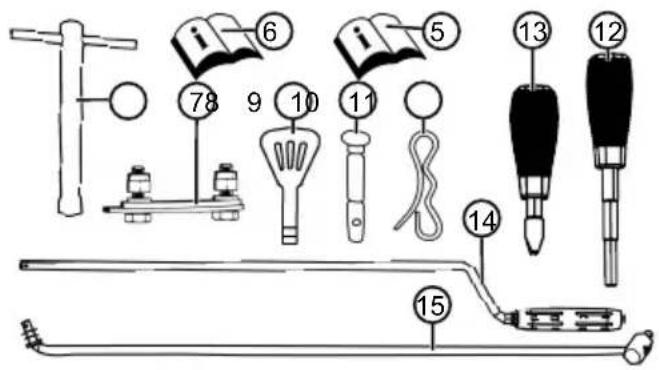
KbM 6xbata Ha Doctabkata npHaJnejat nocoueHnte Tuk no3uun. PpOBepTe, daNN BCnKnno3uun ca BKNoueHN:
He 6bpkaiTe n He CTbNbaiTe B TpaHCnOpTHnA WHeK!

IpeiBcKaKbpa6oTa no ypea n3KJIOUBAIte DBnraTeJI.
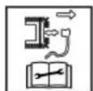
Ipei pa6oTn ITO texHnueckoto 06cnyXbaHe n peMOHT n3BaXdaTe ukepa Ha 3anaNTeHaTa CBeu.
ДрькTe octaHaJIte xopa daney ot onachata 30ha!
Bbptrae Ce yactn B 30HaTa Ha n3- XBbpJHrTo! ONaCHOCT OT 3aBInuHe!
2.5.2 3Haun 3a 06cnyXBaHe
Cnmbon 3haueHne
CTapToBa Knaa CLOSE (3ATBOPN) / OPEN (OTBOPN)
ra3 BaBHO/6bp30


Cnmbon 3haueHne
Klou 3a Dnuratena BKn./M3kn.
KpaH 3a TOpNBOTo OFF (3aTBopeHo) ON (oTBopeHo)
CTapTOB 6yToH


3aBnXBaHe Ha Sheka CtapTnpaH/cnpaH
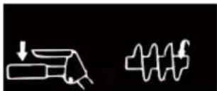

PnDnBxBaHe CtaptnpaHc /cnnpaHc


I3paBnBaHe Ha ycTPOINCTBOTo 3a N3-XBpPnHe Ha CHrC MaHbena
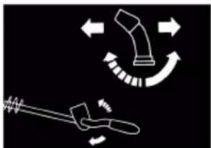
CnmboJ 3haueHne
Hactpoika Ha BucounHaTa Ha 3XBpIaHe Ha Chera C nocT
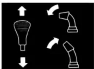
2.6 IperIeHa npOdykTa 620 E III (01)
IperJIeIbT Ha npOdykTa (01) daBa npEicTaBa 3a MaunHaTa.
No KomtoHeHT
1 OToJIaEMn DpbKKn
2 PpeBknOyBaTeJ 3a OCBETneHnE
3ПревкючытелзаOTONпенetoHa npKNTe
4 Pe3epBn cpr3Baun 6oJTOBe
5 CbeHINHTeH IOCT 3a 3aBnKBaHeTo Ha WHeKa
6Ioc3apeyJnpaHeHaBncouHaTaHa 13XBbPJIaHE
7IocT3a n36opHa cKOpocT, 6 npEHNn cKOpocTN23aHn
8 CbeHnHTeHnOCT 3a npnBnXBaHTo
9 DeΦJIeKTop npn yCtpoIcTBOTO 3a n3-XBbPnIe Ha cHra 3a HAcTpoIka Ha Bn-COuHHa Ta Ha n3XBbPnIe
10 YcTPOIcTBO 3a n3XBpJIHe Ha cHera CbC 3aUNTa npOTNB 6bpKaHe B Hero
11OCBeTJHeHne
12 MaHbEa 3a peryIpaHe Ha nocokata Ha n3XBpJrHe
13 Kanayka Ha pe3epBoapa
14 Kanayka 3a DoJnBaHe Ha MacNo
15 PpeDnaeH kanak
16 NocntBaUHCTpymeHT (3aKpehen 3a npedna3HnKaNAk)
17 电kep Ha 3anaHTeJHa CBeu
18 TpaHcnpTeH uHEK
19 N3XbBpnao kOJIeNo
No KomnoHeHT
20 NocntBaUa nlaactHa
21 Perynpyem no BucOuHa nIb3raU
3 YKA3AHNIA 3A BE3ONACHOCT
ONACHOCT! Onachoc3a XnBota n OnachocOT TeKKn HapaHbAHHa! He3HaHneTo Ha yka3aHnraTa 3a 6e3OnachocT Na HnCtpyKcNHTe 3a yNoTpe6a MoKe Da DoBeDe Do TeKKn TeNeCHN NOBpeDN I DOpN Do CmBpT.
CnauTe BcunK yka3aHna 3a 6e3oNaChoc T N HCTpykUn 3a yNtpe6a, npeDCTaBeHN B TOBa pkoBoDCTBO 3a pa6Ota, KaKTo I Te3N, KOnTO ca UNTnpAHN 3a MOMHTa PpeDi yNtpe6a Ha ypeDa.
CbxpaaHbAte BCNUKIOCTaBeHN Bn DOkyMeHTn 3a 6bIeUa yIOTpe6a.
PNEpyPExEHE! OnachocT OT noXap n ekCnNo3n. B cneIcTBnHa n3TuAio ropInBO ce 6bpa3yBa B3pNBOOnacha Cmec OT 6eH3nH n B3dYx. B3nnAmehraHe, ekCnIO3n i NOXap Morat Da IOBeDat DO cepNO3n HapaHBAHn I DOpn CMbPT, aKO rOpNBOTo Ce MaHnPyJnPa He npabnHO.
Hnkora He octabraIte Dbratela nped otKpnt IlaMbK NnN n3ToCHNu Ha TOnJInHa.
He pa6oTeTe c DnurTaTeNa B roPmAcpea.
PNEUYPEXKDEHNE! Onachoct OT hapa-HaBHe Nopadn NOBpeDeHa MaunHa. Pa6otaTa CdeEeKTHa MaunHa MOKe Da DoBeDe DoTeKk HapaHbAHn yBpeKDaHn Ha MaunHa-Ta.
Pa6oTeTe c MaunHaT, KOraTo He e DepeKTHa NIN NOBpeHn He JINCBat Yactn NIMMa He3akpeHn Yactn.
PPEyPExEHNc!OnachocOTBbtpTaeNcyeactnHaMaunHata!BbpkaHeTO BvBVBbptAeNceYactnHaMaunHaTaBOINdoTeKnHapaHbAHnI
Hikora He 6bpkaTe BbB BbpTzaNca TpaHCnOpTe HneK!
PENyPExHEHNE!OnachOCTOT HapaHbAHe.KeHTteN3KJIoueHN yCTpOInCTBa 3a6e3oNaCHOCTN3auNTaMOratDaIOBeaTdo CepNo3HN HapaHbAHn.
PemontupaTe IepeKTHnte npedna3Hn 3a- uHTHu cTpoiCTBa.
Hikora He npemaxbaIte 3aunTHnTe n npedna3HnTe yCTPOIcTBA.
3.1 Yka3aHn 3a 6e3oNaCHOCT CbIaCHO ISO 8437 PpInJoxKeHne A
PpeBapnteHa noDrotobKa
1.Почete TE BHHMaTeJHNo yNbTBAHeTo 3a ynoTpe6a n TexHnuecko O6cnykBaHe. 3aNo3HaTe ce BHHMaTeJHNo C qactNeTe 3a ynpabJIeHne N npabNJHaTa yNtpe6a Ha MaunHata. HayYeTe ce 6bp3O Da cInpate MaunHaTa n da MoKte Te 6bp3O Da n3KnIOuBaTe ynpabJIaBa- uIte eIemEHTN.
2.BHnKaKbB cnyaH He Tp8Ba Da ce pa3pe- 1aHa Deua da pa6oTc C yCTpoiCTBOTo. Pa6oTata C yCTPOINCTBOTo OT Bb3paCTHN, KOHTO He ca 6nN O6yueHn PpaBnHNO, B HnKaKbB cnyaH He MoKe Da 6bDe pa3peWeHa.
3. B 30HaTa Ha yNoTppe6a Tpr6Ba Da e Cbo6oHa OT Xopa, Oco6eHo MaIkn Deca N OT DoMaShn IIO6bMUn.
4. Прп работа DeиctBaIte MHORO BHNMaTeJHNO, Oco6eHo прдвижене Ha 3aEN XoI, 3aДа npedOTbpaTITe nIb3raHe nII NaJaHe.
IoprotoBka
- Поверете Виимателно 30ната, в Когто ще ce ИЗползва машината и OTстраhte BCИКИ пагорve, пььзгачи, дьски, Телови Др.Чуждп Тета.
- CbeHHeTe MaHHaTa HAnbNHO I BKNIOte Ha npazeh XOD, npeDN da cTapTnpaTe DnraTeIa.
- He pa6oTeTe c MaunHaTa 6e3 noDxOJaIo 3mH0 o6IeKnO.HocTe 6yBKn, KOnto ocNrypBaT Cta6nHa CToiKa Bbpy XNb3raBa OCHOBA.
- BhimataJHo 6opabeHe c 6eH3nH, Toi e JecHo 3aapanm.
I3non3BaIte npabuHa Tu6a 3a 6eH3nH.
He 3apekdaIte Dbratela KoraTo pa6oTn nnB 3aqrpto cbctoHne.
■Пьнhte БeнзИновая peЗервоap Bиharу Ha otКрпTO C OсОбЕно ВиHMанe. ИкORA He Пьнhte БeнзИновая peЗервоap B 3aTBopeHи NOMEшеня.
3aTbopete I06pe kanaqkata Ha pe3epBoapau nOTCTpaHETe pa3Netn8 6EH3nH.
1. 3a BCnUKN ypeN c eJekTpnuEcko 3aBnXBa-He nIeKtpnuEcko 3aIaNbaHc Tp6Ba daCe N3PON3Ba 3a3eMeH 3aIHTe KONTaKT.
2. PerylnpaTe BnCOUnHaTa Ha KOpnyCa Ha KOJIeKTopa, KOraTo NocCTBaTe NOBbpxHOCTN OT YaKbI IIN MaKaJaM.
3. HnKora He ce onntBaIte Da npomeHare Ha- cTpOuKn npa6oTeU, DnuratEn (C n3KIOueHne Ha CnyaHTe, B KOnTO TOBA n3pnuHO e npenOpbuaHo OT npoN3BODInTeJ).
4. OcTaBeTe DnRaTeN MaunHaTda ce oxJaAraTdo OKoHata TempePaTpa npEi Da 3aNoUHeTe da NouCTBaTe Chera.
5. Pa6oTaTc BcKa MoToPn3nPaHa MauHnAmOKe Da DoBeDe Do N3XBbPnHe Ha UyKnIpeDMeTn B OChTe. 3aToBa BNarHnocTeIpeDna3Hn OCHNa IIN 3aUHTa Ha OChTe NOBpMe Ha pa6oTa, HAcTpoiKa INn peMOHT.
6.ИЗползваite aHTифон,3aда n3бeгнete yBpeждане Ha cnyxa.
UnpaBneHne
1.He noctabraye pbuete nn KpaKaTa CN B 6n30CT nn NOI dBNKeUITE ce Yaactn. CToIte Ha pa3cTOrHHe OT OTBopa 3a n3XBpJIaHe.
2.БbTe N3KIOUHTeHNO BHIMATEHNI, KOraTO N3NoJ3BaTe MaunHaTn OyakbNeCTn aEn, PbTeKn nn yIuNn nn nPecNuate. BHNMaBaIte 3a CkPHTn PpeYrTCTBn nn eBeHTyAJIHO DnXKeHne Ha IpeBO3Hn CpeDCTBa.
3.AKOceHaTbKHeTe HaUyXd OBeKT,IN3KIOUcTe DnIraTeNIA3BaTeTe Ka6eNa 3a 3anaBHe,BHIMMaTeJIHO npOBepTe CHEROpHnA 3a eBEHTyaJIHn IOBpeDN ITO nonpaBeTe,IpeDN Da pecTapTaPeN IN3NON3BaTe OTHOBO.
4. Ako MaunHaTa Bn6pnpa Heo6uayHo, n3-KnOyTe DnIgATEJ N BeHara NotbpcTe npUnHaT. Bn6paunTe no npHcIn ca 3HaK, Ye mMa npo6nem.
5. BnHaHn n3KnIyBaYte dBNraTeJIa, KOraTo npEkbCbATE pa6Ota, npEi Da noUcNTe Kopnyca Ha KoJIeKTopa/3aDvBxKBaUTo KOJIeNo IJIn JeHTaTa 3a N3XBpJrHe N KOraTo npEepnpeMaTe peMOHTn, HAcTpoIKu INn NHcNeKznn.
6. Korato npednpneMaTe pemOnTu, HacTpoKn IIN INHCNEKcN yBepTe ce npedToBa, Ye KOJIeKTopa/3aADBbXbAaTO KOJIeNo I BCNUKn IOdBHXH N acTn ca B nOKoI. N3BaTe 3a- NaBbUaJNa Ka6eN I rO dpBXte daJeOT 3a-
naHTeHaTa CBeU, 3a Da npedOTbpaTne HeKeNaHO 3anaBae. Pn eNeKtpoDbNarateI Tp6Ba Da ce n3BaDi 3axpaHbuaa Ka- 6eI OT KOHTaTa.
7.He BKIOUbaIte DbIraTeJra pa6OTn B 3aTBOpeHn NOMEueHn,OCBeH npN CTapTnpaHe nn 3a Da npuBnxNte CHEROpHa B CrpaJa nn Da ro n3BaNte OT crpaJa. PnTOBa OTBOPeTe BpaNTe HABh; n3ropeNte ra3OBe ca OnaCHn.
8. He nouchTbaIte cHr nO CKHOHOBe. bJeTe MHORo BHIMaTeJIHN, KORATo npABnTe 3aBOJ NO CtpbMeH Tepen. He ce ONITBaIte Da no-CHCTBaTe Chera nO CtpbMHN CKIOHOBe.
9. Hukora He n3noJ3BaITe cHerOpHa 6e3 npedna3HnTe Kaau, npedna3HnTe KaHnU nn Dpyrnpedna3Hn yctpoiCTba.
10. HnKora He n3noJ3BaIte cHerOpHa B 6n-3OCT Do OCTbKJIeHN OBeKTn, ABTOMO6NJN, OTKpTN WaxTN, CTpbMHN TepEH N dp., 6e3 cbOTBETHo Da HAcTPOnte NocOKaTa Ha n3XBpJIaHe Ha Chera. Pa3eTe DecaTa n DomauHInTe JIO6m4n DaJeY.
11. He npetobapBaIte MaunHaTc MHOrO 6bp30 NOUCTBAHe Ha Chera.
12. HnKora He n3noJ3BaIte MaunHaTa NO XJb3- rABn NOBbpxHOCTNC BWCOKa CKOpOCT Ha npDnBnXBAHe. BHImaHne npn npDnBnXBAHe Ha3aI.
13. Hnkora He hacooybaTe n3xBbPnHa Chera KbM cTOnuHn H6Jn3O Xopa N He pa3peWabaiTe HAKoN Da 3aCTaba nped MaunHata.
14. П配电и cheTe 3axpaHbaHeto 3a KOJIeKTopa/ 3aBnKBaIoTO KOJIeNo, KOraTo CHEROpINbT Ce TpaHCnOpTnpa NIn HMa Da ce N3NoJ3Ba.
15.ИЗПОЛЗВайтесамо OДОБрЕн OТ ИРОПЗВОДИТЕЯ HA CHEROPИHA ДОЛьНИТЕЛПЧАСТИ NAKCECOAPN,КATO HApP.TeЖECTI 3a 6aJIaHc NуразвHOBECSBAHe,KOpIycиДр.
16. He pa6oTeTe cbc CherOpHa npn lo7a BUNMOCT nnn noo ocBETneHne. OcnrypaBNTe CN BnHaTn Cta6nHe CToeX n DpbkTe 3dpaboDp6knte.Pa6oTeTe camo c xOJeHe, HNKORA He 6raIte.
Pndpbkka ncbxpanHeHne
PNEpyPExEHE!Bb3moXn ca cepno3Hn HapaHbAHn Ha pBcTe npn noChCTBaHe Ha KaHaJa 3a n3XBpIne!OkoCBAHeTo Do BbPTaIeTce ce pa6OTn KOJIeNa B KaHaJa 3a N3XBpIne BOi DO cepNo3Hn HapaHbAHn Ha pBcTe. Toba ca Han-yeCTte cnyaHa HapaHbAHn Prn Cppe3nte 3a Chr. 3a noCHCTBaHe Ha KaHaJa 3a N3XBpIne:
I3KJIHcTe cHerOpHa!
I3yakaTe OKoTo 10 cek. DOKaTO BbpTtOTo ce KOneJo cnpe.
Bunaru n3non3BaIte 3a noUcTbaHe Ha KaHaJa 3a N3XBpIYe NOxOJrHnHCTpyMeHT.
Hnkora He n3non3BaIte 3a nouCTbaHe KaHaJa 3a n3XBpIYe pIeTe cn!
- PeoBHO npOBepaBaiTe daHn npEpa3HnTe yctpoiCTBa, BnHTOBeTe Ha HOXOBeTe, BnHTOBeTe 3a 3akpenBaHe Ha DBuRaTeJIrN dp. ca Do6pe 3aTeHaTn, 3a Da rapaHTnpaTe 6e30-nacha pa6ota Ha MaunHaTa.
- HnKora He cBxpaHraBaTe MaunHaTa B crpa- da Cn3ToUHnCu Ha 3aapanBaHe, KaTO ypeDN 3a ropeua BODa, eJNEKTpuYeCKn DuxaJIKN, cyuINHN n dp., DOkATO B pe3epBoapa Ima 6en3HN. PbPBO OCTabeTe DBnIaTeNJa ce OxlaDn, npEdu Pa npbEpPeTe MaunHaTa B 3aTBopeHo NOMeueHne.
- Binhari cIeDbaIte ToHnTe HNCTpyKuIN B pBkoBOdCTBOTO 3a EKcIIIOaTaUria, AKO CHeroPunbT Tp6Ba Da ce CbXpaHraBa 3a INo-DbJIro BpeMe.
- Octabete BCnukn Ta6eJkC nHCTpyKuun 3a 6e30napcHocT n EKCnIooataun Ha MaunHaTa nn rncmHeTe, aKe e Heo6xOdmo.
- CneI KaTo noUcHtnte Chera, octaBeTe Ma- uHaTa Da pa6OTn HAKOJIKO MInHTu, 3a Da npEDoTbPaTnte 3ampb3BaHe Ha KOJIeKTopa / 3aDbNkBaUTo KOJIeNo.
3.2 Yka3aHnna 3a 6e3oNaChocT npn o6cnykBaHe
I3no3BaIte MaunHaTa cAmo 3a pa60Tu, 3a KOnTO e npedHa3HauHeHa. YnOTpe6bTa He no npedHa3HauHe MeOKe Da IOBeDe Do HapaHЯBaHry, KaKTo N DO NOBpeDa Ha IMyUe-CTBO.
He n3noI3BaIte ypeDa c n3HOceH nIe De-ΦeKTHn Yactn. BInaHr 3aMeHraTe DeΦeKTHne Yactn C opINHaHn pe3epBHN Yactn Ha npOn3BOJnteJ. Ako ypeDbT 6bNA ynoTpe6BaHc n3HOceH nIe DeΦeKTHn Yactn,
HeMOratIaCeIpeJRABaTBAJIINHrapaHcUHOHHNCKOBEKbMIPON3BOIDNTeJI.
B cIeHnTe cIyuaI n3KIOUcTe DBrTaTeJI, I3uKaIte MaunHaT a cIpe I n3BaIeTe Iuekepa Ha 3aIaNITeINHaT a CBeU:
PnOtdaJeYBaHeOTMaunHaTa
Pn pa6oTn No NOuNCTBaHcTo Ha MaunHaTa n PpKKaTa
PpeIN BCNUKn pa6oTN no HacTPOiKaTa
PnnoBaHa HEn3npaBHOCTN
npeDn da ocBooDnTe 6JOKIpOBKInTe
Ipei Da OTCpaHnTe 3aDpbCTBaHnTa
CneI KOHTaKT C UyKnTeJa
PnI NOBa Ha HEn3npaBHOCTN I Heo6uHaHn B6paun No MaunHaTa
He n3no3BaIte ypeDa noD Bb3deiCTBneTo Ha aIKOXoN, HApKOTnHn BeuecTba nn Je-KapctBa.
3a da n36erHeTe HapaHbAHnNo rnaBaTa N KpaHnUnte, KaKTo u yBpeJdaHnHa cIyXa, Tp6Ba Da ce Hocn 06NeKnO nPpeJa3Ha eknnnpOBka cnopeu 3nckBaHnraTa.
Obleknoto Tpa6Ba Da e celenecb06pa3Ho (nIbTHo npInenHaNo) n He 6nBa Da npeHu Ha DvIXeHnTa. Hnkora He Hocete dpexn IIN aKcecoapu, KOTo MoarTa da 6bDaT 3aB- neeHN OT MaunHata, HanpImep 7aJIOBE.
Личнite педпа3на ekнировka ce cbctonOT:
3aunTaHa CnyxH npedna3H OuHa
3dpabn Hennb3raun ce o6yBkn
PpeDn3Hn pBkAun
Дрьжte рьцete Ии КракаТа Ии Дpyгчac-н ТЯлOTо IдрexNTe ДалЧOT pa6OTe-шOTO NOuchCTBaUTo rpe6No, TpaHcNOpTHnIshHeKИИЗXBbPnAToKOneNo.
CnauBaIte MeCTHInTe pa3npoe6n 3a pa6oTHOTo BpeMe.
He octabraye 6e3 haD3Op ypeI roTOB 3a pa-6ota.
Hikora He nouchTbaIte cIg no nokpInB.
3.3 Pa6oTa c 6eH3nH macJo
OnachocOT ekcnno3nI noxap: Cb3daBa ce ekcnno3nBHa aTMocpepa ot n3TnuaHe Ha cMec 6eH3nH-Bb3dyx. Bb3nnaMeHraBaHe, ekcnno3nI nNoxap Morat da DoBeDaTdo cepno3Hn HapaHbaHn I DOpN
CMBpT, aKo rOpBOTO ce MaHnnyInpa HnpaBnHOb. B3eMeTe IOI BHNMaHne CJIeDHOTO:
He nyuweTe, koraTo pa6oTnte c 6eH3nH.
Дрьктseбензиha caMo Ha OTkpnto n HnKORA B 3aTbOpeHn NOMEuEHN.
HenpeMeHHo cna3BaIte nocOeHNTe TyK npaBnna 3a pa6ota.
TpaHcnpTpuaTe n cBxpaHraBaTe 6eH3nH mAcna camo B Odo6peHn 3a CEJTa KOHTeHepn. YBepeTe ce, ye Deuata HMaT DoCTbN Do CKNaIupaHnTe 6eH3nH mAcNo.
3a da n36eHHe 3aMbpcBaHe Ha noyBaTa (ona3BaHe Ha OKoJHaTa CpeJa), yBepTe ce, Ye NO Bpeme Ha 3apeKdaHeTo B 3emrTa He npOHnKBaT 6eH3n Hm MacNo. N3non3BaIte cyHnra 3a 3apeKdaHe c rOpInBO.
He cTaptnpaIte HnKora ypeDa B 3aTbOpEni NomeuHn. Bbpx npda moKe da ce CTnHrE Do HATpynBaHe Ha 6eH3nHOBn napn, KOeTo Da DOBeDe Do Bb3PnAmEHaBe nN EKcPiO-3nJ.
N36bpcBaIte He3a6abH0 pa3JIrTO TO rOpNBOOT ypeHa n OT 3emra. OCTaBeTe Kbpnnte, cKoNTO CTe N36bpcAIN 6eH3nHa, Da n3cbxHaTHa Do6pe npOBeTpEHO MRCTo, ppeDi da nN3XBbPnTe. B npOTiBcH cnyaM MoKe da ceCTnIHe DO BHe3aHNO CamO3aNaJBAhe.
Ako cTe pa3cunapan6eH3nH, ce 06pa3yBat 6eH3nHOBn napn. Nopadn TOBa He cTAPtn- paIte DnIraTeJna HcBIoTO MRCTo, a HaIMaIKo Ha 3 m pa3CTOHNHe.
I368BaIe KOHTaKHa KOKaTa C MInHepaJIHn npOdykTN. He BdUWBaiTe 6eH3uHOBITE na-pn. PpN 3apeXdaHe HocTe BuHaR npeDna3-Hn pBkaBnC. CmeHne I NOuCTBaIte 3a- uINTHOTo O6JIeKIO peIDOBHO.
BHHMaBaIte 6JIeKJIoTO Bn Da He BnI3a B KOHTaKT C KOKaTa. Ako Bbpxy 6JIeKJIoTO Bn nonaIHe 6eH3In, CMeHeTe DpexNTe He3a- 6abHo.
Hikora He otBaprTe kanaqkata Ha pe3epBoapa npa paboTeu nnropeu Dnurat.
Hnkora He 3apekdaaTe ypeDa c pa6oTeu nnropeu, DnBiratEn.
Hnkora He npenbIbaTe pe3epBoapa (6eH-3nHbT ce pa3wnpraBa).
BHHaru 3aTbapnTe Do6pe KaNaqKaTa Ha pe-3epBoapa.
CmeHeTe NOBpeDeH pe3epBoap nn Kanauka.
Pn nJIHeHa 6eH3nH nIi MaCNo He JkTe, He NInTe Hn He NyWeTe.
Ako e n3TeKbJ 6eH3nH:
He cIapTnpaIte DnBraTeIe.
I36raBaiTe OINTu 3a 3anaBaHe.
IOnnIte pa3JIeTna 6eH3nH cbc Cbbp3Ba- IIO BeIeCTBO IIN KbpNa N13XBbpIeTe npaBnIHNo.
IOnuNcTeTe ypeJa.
Ako e n3TeKNo DnIraTeJIHo MaCNo:
He cIapTnpaIte DnBraTeIa.
IOnnTe pa3TTOMaCNo CbC CBbp3Ba- ⅢO BeueCTBO IIN KbpNa N N3XBpJeTe npaBnHIO.
IOnuNcTeTe ypeJa.
4 PA3OPIAKOBAHE HA MALUNHATA (02)
PNEyPExEHNc!OnachocOTnpema3BaHe npaHn ppeo6pbuahe!MaunHaTeKka!Korato ce hakIoH, e Bb3MOxHO da ce3akneTtactN OT TAnOTO uOBeK Da noJyTuTEKka TeLecHa NOBpeDa.
3aIbJIxHTeJHo e da ce noDCnHyprT noHe DbAma YOBeka 3a pa3ONaKObaHe Ha MaUnHa-ta!
1368BaIte HAKJIaHHeTo Ha MaunHata!
Maunnata, 3aeHc BCnukte n npnaJnx-HocTn ce doctabB kaptoheHa Kytna. KytnaTa ce Hamnpa Bbpxy EBponanet.
- NocTaBeTe KyTnra Ta Bbpxy IlaIka n paBHa NOBbpxHOCT.
- OtctpaHete naketaxHHte JeHTN.
- OTbOpTe KyTnTa ot rope (02/a).
- Otrpahe Te onakOBbHnT MaTePnaI.
- BnMaTeJIHO B3eMeTe He3aKpeNeHnte qactN, NaKeTa C Dpe6HnTe npHaJnxKHOCTN n pb-KOBODCTBOTO 3a ekCnNoaTaunr.
- 3aHaTa CteHa Ha KyTnraTa (T.e. TaM, KbTeTo ce HAMnpa DnIraTeJIa) CpexeTe BHNMaTeJIHO C HOK, Taka Ye Da He Ce HapaH MaunHaTa.
- CnycheTe HaOny 3aHaTa cTeHa Ha KaWoHa (02/b).
- BHIMATEJIHO OTCpaHeTe OCTaHaJInte He3aKpeNeH YuACTN, KaKTo N ONaKObUHHa MaTePnA1.
9.И36ytaIteHa3aICherOpHa N3BbH KyTnaT, T.e.C MOTopa Happe (02/c).
5 MOHTAX
PNEpyPExEHE!Onachocn npaHn HEnbIeM oHTax!Pa6oTaTc HEnbIHO crNo6eH ypeD MoKe Da DoBeDe Do cepNo3Hn paHraBaHna.
Pa6oTeTe c MaunHaTa cAmO KOraTo e Ha- nblnHO MOHTnpaHa!
Ipei Da BkIIOUHTe, npOBepTe BCnUKNpeIa3Hn 3aunTHN yCTPOJcTBA, 3a da ceyBepTE, Ye Te ca HAnuHN n FyHKUOHaJIH!
Heo6xOaIMn HhCTpyMeHTN
| № Исторгия |
| 1标明ов几乎所有 заимеяен клич SW 10 (x2) |
| 2标明ов几乎所有 заимеяен клич SW 13 |
| 3标明с вътpeшенишисточen 5 mm |
| 4标明的所有 Клич STИЗ |
| 5标明ka |
| 6 Масло за наслбке |
| 7标明的所有 Альперен В entил |
5.1 MoHTuPaHe Ha DoHaTa dpbXka (03, 04)
MOnTnpaIte DoJIHaTa DpbKka BJIaBO N BdACHO dony Ha cpe3ata 3a CHr.
- Pa3BnTe 6oJToBeTe (03/1).
2.ФИКСИРаTeДОЛнHaTаЧaT HaДрБЖКaТa (04/1). - Πьхhte 6олтobete (04/2) npe3doJIHaTa Част Ha ДрьжkaТи 3ДравО 3aTeHete.
5.2 MoNTnpaHe Ha nHaEna 3a ynpaBneHne (05)
- OT JIyBO Ha DoJHaTa DpbjKka: Pa3Xna6eTe 2-Ta 6oJTA (05/1) Ha qnknpaunbIbI (05/2) n CHEMeTe 3akpenBaunbI.
- NocTaBeTe roPHaTa dpbKka (05/3) c naHeNa 3a ynpabJeHne.
- OTДясноHa roрнataДрьжka:ПьхHeTe 2-Ta 6oIra (05/4)пpe3 roрнataиdoHnataДрьж- KaKaTo rN 3aBnTe 3dpaBO 3aeEDHO C NOJ- loxHnTe шaibn ngraKnTe.
- OTЯBO Ha ropHaTaДрьЖka:ПьхHeTe 2-Ta 6oJtA (05/1) npe3 ropHaTa,doJHataДрьЖka
IΦHKcnpaunbKbN KaTO JIeKO rN 3aBbPNTe CTeHato, 3aeDnO C NpOJIOXHnTe WaIbN I raIKnTe.
5.3 MoNTaK HacTpoiKa Ha XnIaTa 3a 3aBnXBaHeTo Ha XoObAta Yact N Ha ShHeKa (06 - 11)
- 3aKaayete Jnno (06/1) 3a npuDvXBaHeTo (06/2) BdoHnO oTbOp (06/3) Ha deChnA loCT.
-
3aKaayete Jnno (07/1) 3a 3aBnKBaHeTo Ha UHeKa (07/2) B roPnIy OTbOp (07/3) Ha IeBnIIOCT.
-
PerynipaiTe KnilaTa KaKTo CneDbA:
Bbptete perynaTopa Ha xinoto (08/1) no nocoka Ha cTpeIkata (08/a),doKato xinoto He npOBnCBA NOBEue (JeKO e o6- terHaTo).No Bpeme Ha BbptHeTo dpxKTe BbxKeTo 3dpaBO, 3a Da He ce ycye.
3aTeHHeTe (08/b) KOHTparaiKaTa (08/2).
4.ФИКСИРаTe XINaTe (09/1) 3aeIHO C KIneMnTe (09/2) BnABo N BdЯCHO Ha IpbXkKaTa.
5. OnbbaHe Ha XnIIOTo:
Pa3xna6eTe KOHTparaKnTe (10/1, 11/1).
3aBbptTe HakpaHnka Ha pe36aTa (10/2, 11/2) Harope dokaTo xinoto ce onbHe.
HabnTe KOHTpaarauKNTe KbM Boaaya (10/3, 11/3), 3a da fNkCnpate JINIOTo.
6.ИЗТЕТЕнДОу(10/a,11/a)rymeHOTO yIbTHeHne(10/4,11/4)BbpxyKoHTparaIKn-Te,3a Da ce 3auNTn JINOTO OT KOpO3nI.
5.4 DonbHnTeHNO peryInpaHe Ha XnNoTo (12)
HnHaTa HacTpoKa ce OcbIeCTBra NocpeDCTBOM perynpa6oNT.
- Pa3xla6ete (12/a) KOHTparaIKnTe (12/2) Ha perylnupaun 6oNT.
- 3abptete (12/b) perynupaun6oT (12/3), 3a da ydbljnte nn CbKpatnte XOda Ha JnIto. BHMabaTe, KINOTO da e neko onbHato n da He npOBncBa.
- 3aBnTe OTHOBO 3dpaBO (12/a) KOHTparaKuTe (12/2) Ha perynpaun6oT.
5.5 Поберка на HabстpoиkaТа на КИЛOTO (13)
KINOTO 3a 3aBnKBaHe Ha XoOBaTa Yact Ce yIbIkaBc BpemTo. Ako npi pa6oteu MOTOP 3aBnKBaHeTo Ha XoOBaTa Yact He MoKe Da ce
BKNIOH,TOBa 3HaHu,Ye XINOTO e CTAHaIIO TBbp-De DJIro N Tp6Ba Da ce Ckbcn.
1.ИЗкlioуeteуpeda(BnK2na6a6.8"ИЗкlioу- baineHa deuameN3(37,38),cmpaHua 323).
2. PerynipaTe OTHOBO XINOTO (BIX 2naBa 5.3 "MoHmax u HacmpoUka Ha XUnama 3a 3ad-6uxbaHemo Ha xodoBama yacm u Ha WHeKa (06 - 11), cmpaHuza 320).
3a npobepka Ha hacTroKaTa Ha JxINOTO:
- CtaptnpaTe MOTopa (BnK 2na6a 6.7 "Cmapmupane Ha deusameTn (31-36), cmpaHua 323).
- BkIIOUeTe ckOpocTt a n (BIX 2naBa 7.1 "CmapmupaHe Ha pexuma 3a noucmbaHe Ha cHra (39 - 41), cmpaHuua 324).
- HatncheTe 6abHo haOny (13/a)ЯСнata pkoXbTaKa (13/1)Ha 3aDbNkBaHeTo 3a npDnBxBaHe,doKATO ce yceTn JIeKO cBnpOTNBJeHne. YeHTbpa Ha Hatnck Ha CbeDnHn-TeJra e yCTaHOBeH.
4.Ako 3aDnBxaHTo Ha xoobata qact He ce BkIIOU: NOBTOpeTe NO-paHUnte CTbKn. - Ako Hactpoikkata Ha xinnoTo He e ycneuHa: CbpxKeTe ce cbc cepBn3 Ha npOn3BODnte-
5.6 MoNTiPaHe Ha rpeDa Ha IocTa 3a n36Op Ha ckopoCt (14, 15)
- 3aKaaye rpeJaTa dony (14/1) B otJeHneTo 3a npEbkIuOyBaHe Ha npEpaKnTe (15/2).
- 3akaute rpeata rope kBm locta 3a cmaHa Ha ckopocTta (15/3) B Iernto.
3.Подсигурete rpedaTaДony u rope c noI- loxHn шaBn u npyxHHn uekepn.
5.7 MoHTnpaHe Ha loCTa 3a n36Op Ha CKOPoCT H BnCOUHa Ha n3XBbPJIHe (16)
- CnojKeTe npyKHHnTe 7aH6n (16/1) Ha pe3-6ata.
- Hauitte locta 3a BucounHaTa Ha n3xBpIHe (16/2) n 3aterheTe.
- HabuTe IocTa 3a n36Op Ha ckopocT (16/3) n 3aTeHHeTe.
5.8 3akpenBaHe Ha uencena 3a oToPJIeHne n OCBetJeHne (17)
- CbeHHeTe yactnte Ha uencela (17/1) 3a OCBETJIeHHeTO I OTONJIeHHeTo.
2.Obe3onacete 电encelHoTo cbeHHeHne.
5.9 MoNTIpaHe Ha yCTpOncTBOTo 3a n3XBbPJIHe Ha cHr (18 - 21)
- HamacneTe Jeko nIb3raaTa NaOBbpxHOCT (18/1) Ha yctpoiCtBOTo 3a I3XBpJrHe Ha CHrHa CHEROpINA C MacNo 3a HAnPbCKBaHe (MOKe Da Ce I3No3Ba N rpec).
- Пocтавete (19/a, 20/a) устpoиctBoTo 3a n3-xBbPnHe Ha chyr (19/1).
- BkapaTe 3akpenBaun6oNTOBe (20/2) ot BbTpewHaTa CtpaHa npe3 OTBOpnte uycTPOIcTBOTo 3a N3XBpPnHe Ha CHr.
- 3aTeHHeTe yCTpOiCTBTO 3a n3XbPJIHe cbc camooCnIpyBaUc ce raIKn (20/3).
5.BkapaTe 3akpenBaunTe BnHTOBe (21/1) npe3 rolemna HappaBnaBau dNcK (21/2) n noCTaBeTe OTrope MaKnT HappaBnaBau dNcK (21/3). Yka3aHue: Mankm HappaBnBau, duck mpr6ea da neku om2ope bpxy oJemmu HappaBnaBau duck. - BkapaTe HnpaBnaBaunTe DnCKOBe, 3aedHO CbC 3akpeBnBaunTe BNHTOBe OT DOJy BCHEROpHa.
7.ПоДлоЖнITEшайби(21/4)cLOжeteВьрху BИNTOBETe. - 3aTeHHeTe 3dpaBO camOocnpypRAuNTe ceraiKn (21/5).
5.10 3aKpenBaHe Ha XnIo KbM n3XBbPpIaTa KnaIa (22)
Toba JINIO 3aADBIXBA N3XBbPnIaTa KnaIa Ha yCTpOInCTBOTO 3a N3XBbPnIe Ha CnIg N CnyKu 3a HAcTPOInKa Ha BnCOUnHata Ha N3XBbPnIe.
- Okayete XINOTO BbB BOaunTe (22/1, 22/2). Ha BbHnHOTo XInIO Tp86Ba da ce 3akpen rymenr npedna3nteI.
- 3aBbptTe KOHTparaiKnTe (22/3, 22/4) 3paBO KbM BODaHa (22/2) DOkato XNIOTo Ce ONbHe.
3.CIOCTa 3a HAcTpoiKa Ha BnCOUHaTa Ha n3-XBbPJIHe IPOBepTe DbJXnHaTa Ha XnITo:
IpnBnKTe IocTa Do ynop Hanpei. N3XbBpnaTAtkana Tpr6Ba Da ce npD-BnKn N3cANo HaOny.
IpnBnKTe IocTa Do ynop Ha3aI. N3- XbBpIaTa KnaIa Tpr6Ba Da ce npDnBxNn 3zraNo Harope.
Ako e Heo6xOIMO, npomeHeTe IbJxHnHaTa Ha XNJOTO.
5.11 MoNTIpaHe Ha MaHbEJIaTa 3a yCTPOcTBOTO 3a N3XBbPJIHe Ha CHr (23)
- BkapaTe MaHnBeJaTa BBB Odaa (23/1) Ha dpBXKata 3a ynpabIeHne (23/a). Ka3aHue: Kozamo MomoeUrkama He ce deuxu unu mpydno Ce npuduxka KBm doJInu bOaay, pa3xna6eme zoHua U cIed MoHmaxa Ha MomoeUrkama omHo8o 20 3amezHeme 3dpao.
2.Пьхhte(23/b)пружиннuaцер(23/2).
5.12 3aKaayane Ha XnNoTo (24)
- 3aKaayete JnIoTo (24/1) B OTdJeHneTo (24/2) noD dBnRaTeJIa.
6 NYCKAHE B EKCPIIPOATAU
I PENEYNPEXKDEHNE! OnachocT OT HapaHnBaHe NopadN NOBpeDeHa MaunHa. Pa6otaTa C DepeKTHa MaunHa MOKe Da DoBeDe DoTeKn HapaHraBaHn I YbpeKDaHn Ha MaunHa-Ta.
Pa6oTeTe c MaunHaTa, KOraTo He e DepeKTHa NIn NobpeDeHa n He JInCBat Yactn NInNMa He3akpenEn Yactn.
YKA3AHNE Ipei nnyckaheTo B eKcNlnoatauia BnHaI N3BbPWBaIte OrleI. YcTpoiCTBOTO He Tp6Ba Da ce N3No13Ba C pa3Xna6eHn, NOBpeHn nn N3HOceHn pa6OTn / nn 3akpenBaun yactn.
6.1 Pa6oTHn cpeDCTBa
ONACHOCT! OnachocT Oeknno3n noxap. Cb3daBa ce ekcnno3nBHa aTMocpepa OT n3TuHaHe Ha Cmec 6eH3n/H b3dyx. Bb3nPaMe-HaBaHe, eknno3n I NOxap MoraT Da IOBeDaT DO cepNo3Hn HapaHbAHH N DOpN cMbPT, AKO rOpNBOTO Ce MaHnynipa He npabuHNO.
He nyuweTe, koraTo pa6oTnte c 6eH3nH.
ДрьжTe 6eH3nHa cAmO Ha OTKpNTo n HNKOra B 3aTBopeHn NOMEuEHH.
ONACHOCT! Onachoc3a JxNBOta Ype3 OtpaBHe. OTPa6oTeHnTe ra3OBe Ha DnRatJIa CbIbpxaT BvIepoDeH MOHOKnD, KOITOMOKe Da y6ne yOBek B paMKnTe Ha HAKOJKO MNHyTN.
Hikora He ekcnnoaTpaIte DnrgaTeJHa 3akpnto, a cmo Ha OTKpnto.
He BnBbAte Otpa6oTeHnte ra3OBe ot DnIraTeJ.
I3KIIIOUeTe DnIRaTeJIa, aKO NOyBCTBaTe ra-DeHe, 3AmAHOCT IIN Cna6OCT NO BpeMe Ha pa6Ota. IOTbPcTe He3a6abHo Jekapcka noMoU.
YKA3AHNE IV3XBbPneTe OTPa6oTeHOTOMOTOPHO MacNo 6e3 Da 3acTpa7aBaTe OKJNaTaCpeDa! PpenOpbUbame OTPa6oTeHOTo MacNo daCe IpeJaDe B 3aTBOpEn CbD Ha ueHTbp 3a peuKJInpaHe NIN CEHTbp 3a O6cnyXbaHe Ha KJIneHTN. OTPa6oTeHOTo MacNo He Tp8Ba Da ce:
n3XBbprp npn 6ntOBNTe OtnaBcN
N3CINBa B KaHaJIIN3aIyTa NIn IpeJIINBHNzI
N3JIbBa Bbpxy 3emTa
YKA3AHNE Cna3BaIe npuIooKeHTo pkoBODCTBO 3a ynoTpe6a Ha Dnuratena!
Ipei NyckaHe B eKcnloaTaunr Tp6Ba Da Ha- nblnHte DBrnte N da 3apeNTe CHerOpHa. Yka3aHn3a 6eH3nHa N MacNTo 3a DBrnteBnK TexHnuecknte DaHHN.
6.2 HanBaHe Ha DnRaTeJHo MacNo (25)
- Pa3BnIe KaIauKaTa 3a HaJIuBaHe Ha MacIIO(25/1), OCTaBeTe KaIauKaTa Ha YIcTo MRC-TO.
- HaneiTe macNo c nomouTa Ha yHnA.
- Поверете сбсторнeto Ha 3апьлвае C MacNON3МерВATEЛНаТа npьчka, ВИЖ рькOBODCTBO Ha DBИralteЯ.
- 3aTbOpTe Iobpe OTBopa 3a HauNbaHe Ha MacNo N NOuNCTeTe.
6.3 Hanibahe Ha 6eH3nH (25)
- Pa3BnIte KanauKaTa Ha pe3epBoapa (25/2), OCTaBeTe KaNaUKaTa Ha YNCTO MxCTO.
- HaneTe 6eH3nH c nOmoUta Ha yHna.
- 3aTbopeTe Iobpe OTbopa Ha pe3epBoapa N nouCTeTe.
6.4 NpOBepka Ha HAnraHeTo B rymnte (26)
- HatncheTe cbeHnHTeHHa NOCT (40/4) 3a 3aBnKBaHe Ha uHeka (40/a).
- Hatachete cbeHHTeHnna loct (41/5) 3a npudBxBaHe (41/a).
7.2 CnnpaHe Ha peXmHa 3a noUcTbaHe Ha cHr (42)
- OTnycheTe cbeHnHTeHHnJIoCT (42/1) 3a UHeKa n 3a npuBnKBaHe, T.e. pa3eHHeTe (42/a).
3a da npedotbpatnte 3ampb3Bahe, octabete TpaHCnOpTNIA WHeK IN 3XBpIaTO KOneLo Da npOdbJxkAT da pa6oT, DOKATO B 3HaunTeHa CTenE CE OCBO6OaT OT cHera. 3ampb3HaT TpaHCnOpTeH WHeK Ie NOBpeDN KInHOBtPeMbU.
Cheropnhtcnnpa, TpaHcnpTnHT WHeK n 3XbpbJIoTO KoneNo He pa6oTt.
7.3ПпeвклунчынHa ckopoct 3a npnDbvnxBaHe (41-43)
BHIMAHHE! OnachocT OT NOBpeHa Ha ype-da. CkopocTe ce noBpeKdaT, KOraTo npeDi CMraHa Ha cKOpocTTa HMa pa3eDInHЯBaHe.
Pbpo pa3eHHeTe, cJeD KOeTO CMeHeteCKopoCTTa.
- Ocbo6oTe cbeHnHtHnHa loCT 3a npuBxBaHe (42/1), t.e. pa3eHnBaHe (42/a). Yka3aHue: TpaHcnpmHuam wHeK bokupa, Kozamo npu eNaKeH u meKbK cHra ce cnpe u cne moBa omHO Bo ce cmapupa. He oc6o6xoDaabaume cbedunHmHnHa noCm 3a npudBuXBeAne Ha wHeKa!
2.Превкючete(43/1)ckopoctTa cbc ckopoCTHЯ loCT. - HataChete cbeHnHtHnHnIocT (41/5) 3a npuBxBaHe (41/a).
7.4 OTeTpaHЯBaHe Ha 3aApbCTBaHnB yCTpoIcTBOTo 3a N3XBbPnA He Ha CHERa (42, 44)
YKA3AHNE 3a n36yBaHe Ha 3aDpbcTbaHnI pN MOKbp N TeXbK CHrI NO Bb3MOxHOCT OTabRyTe TpaHCnOpTHnT IHeK Da pa6OTn.
Ako chebT He ce n3XBpJn npabnHNo, npuHa 3a TOBa MoKe Da ca HATpyNBAnHa Na ChrI N JeI NO TpaHCnOpTHNn IHeK n KaHana 3a n3XBpJn- He.
- OTnycHeTe cbeHnHtHnna loCT (42/1) 3a IHeKa n 3a npDnBxBaHe, T.e. pa3eHHeTe (42/a).
2.ИЗкlioуete MOTopa(BNX 2na6a 6.8 "ИЗкlioу-еHa Ha dbuzamela (37,38)”,cmpaHu-ua 323). - C INHCTpymEnT 3a NOUncTbaHe (44/1) oTcTaHETe BHIMATEJHO CHera OT KaHaJa 3a N3-XBbpJnHe N OT TpaHCnOpTHnA UHeK.
Pn npOdbJkaBaUo HnnpaBnHOn n3XbPnHe Ha cHera nOpbcTe cepBn3.
8 PEMOHT
I PEPDyPPEKDEHNE! OnachocT OT hapaHЯBaHnno BpeMe Ha peMOHTHa DeHOCt.
HenpaBnHnTe peMOHTN DeHocTn MOraT da IOBeDaT Do TeKKn HapaHaBaHn I Do NOBpeNi Ha ypeDa.
PemOHHTHe pa6OTn MORaT Da ce N3BbPWBat cAmO OT cepBn3HInTe ueHTPOBe Ha npOn3BO-DITeJIy IIN OT OToPn3nPaHN CneuNaIIN3npa-HNΦnPMN!
PpoepnoHaJaHn npOBepKa ce n3nckBa BnHa:
CneI npemnHaBaHe npes npenTCTBVE.
PnBHe3aHNO cnpaHn DaBnTaTeJ.
IIOBpeHn TpaHcnpTeH uHEK nIN n3XBbPJIaO KOJIeNo.
9 NOДРьЖKA И NOЧNTBAHE
BHIMAHHE! Onachoct OT hapaHЯBaHe.
Octpopb6ectnn DnBxkeu n Ce yactn Ha ypea Moat da IOBeDaT DO HapaHraHna.
BnHaH npaPbOTn no NOdApkKaTa, 6CJIyKBaHETo n IOuNCTBaHETo HocTe 3aunTH npKabu!
I3knHouTe DnuratEn I ce yBepete, ye e cnpan!
I3BaTe TeKepe Ha 3aNaJIteJIHaTa CBeu!
I ONUCTBaIte MaunHaTc CneB BcraKa yNOTpe6a.OTcPbAHBaIte oO6eHo OTnAraHnraHaTa Ha cOJI 3a nopbcBaHe Ha nTnUaTata.
He npbckaTe MaunHaTa C Boda. IpoHnKHaJa BODa MoKe Da npuHH NOBpeDi (3anaJIHTeINHa cnCTema, Kap6ypatOp).
BunHn CmHnTe DeΦeKTHn Wymo3aŋywn-TeJn.
CnataBaiTe rpaΦka 3a noDpBkka.
Cna3BaIe pkoBOcTBOTO 3a eKcnnoaTuaHa DnurataJIa.
9.1 RaΦnK 3a noDpBxKa
PpeBvBaKyaynotpe6a
KoHTpOJIpaIte HNBOTO Ha MacNoTO (BIXTe pBKOBOdCTBOTO 3a EKCnIooatauHa DBNaTeTЯ).
KoHTpOIpaIte cPra3BaUnte 6oNTObE.
KoHTpOIpaIteMaunHaTa3a nobpeN.
IpoBepTe, daH TpaHcnpTHnT uHeK e 3ampb3HaI.
Cnei npBnTe 5 pa6oTHn Yaca
CmeHeTe MOTOPHOTo MacNo (BnXTe pkoBOCTBOTO 3a eKcNloataunHa DnBraTeJ).
Ha BceKn 8 eKcnnoaTaunOHn Yaca
Cma3BaIe TpaHCnOpTHNIA WHeK.
Ha Tprn Meccea
PpOBepaBte HnraHeTo B rMnte.
HamaCnBaIe npbCTeHa Ha yCTpoiCTBOTO 3a n3xBpIHe Ha cHr C MacNo 3a HAnpbcKBaHe.
Toaunho
CmeHnTe 3anaNTeHNHaTa CBeu (BnXTe pkoBOOCTBOTO 3a EKcNloaTuNa Ha DnIraTeJna).
TpecapaTe TpaHCnOpTHmA HeK.
CmHnTe MOTOPHOTo MacNo.
9.2 Cma3BaHe Ha TpaHcNOpTHnA WHeK (45)
HanpaBete OKOJIO 2-3 BnPbCKBaHnHa yHnBepeCaHa rpec c TaKaIaMNT B MacNbOHkata (45/1).
9.3 PdPbXka Ha 3aBnXBaHeTo Ha KOJIeNoTo n UHeKa (08)
PENPYPEXEHNc!OnachocOT HapaHnBaHe npa6oTn no NOdpbKkata.HenpaBnHa NOpdpbXKa MoKe Da DOBeDe Do TeKKn HapaHnBaHnI yBpeXDaHn Ha MaUnHata.
HactpoBaTe XnIOTo cMo npu n3KnUoyen DBNrataTEn.
Cnpete DbngateJra, ako 3aDbNxBaHeTo Ha npDnBxBaHeTo/UnHeKa He MoXe da ce n3- KIOH.
He ce onntBaIte da peMOHTnpaTe camn, a He3a6abHO nOtbpceTe cepBn3.
YKA3AHNE Bnara B XnIOTo MoKe Da DoBede DO KOpO3n I 3aMpb3BaHe. NObpeDeHO XnIIO Tp6Ba Da ce CMeHn.
PerynpaHc HxNIOTo
Ako npu pa6oTeU DnuratEn 3aDnKbaHeTo Ha Xoobata YacT /UnHeKa He MoKe Da ce BKnIOuN NOBuee, Tpa6Ba Da ce perynupa CbOTBeTHOTO KINIO.
- Pa3BnTe KOHTparaKnTe (08/2).
- Bbptete perylataopa Ha kniloto (08/1) no nocoka Ha cTpekata (08/a),doKato kniloto He npOBncBa NOBuee (JeKe o oTeHaTo).IbpeMe Ha BbptHeTo dpbXTe BbxTeTo 3dpaBO,3a Da He ce ycye.
-
3aTeHHeTe (08/b) KOHTparaiKaTa (08/2).
-
3a npOBepka Ha NaHactpOHKata, CTapTnpaTe DnRaTeJI N BkIIOUeTe 3aDnBxKBaHeTo Ha Xo- DoBaTa YAcT/UnHeKa.
5.AKo 3aBnXBaHeTo Ha XoObTa YacT/WHHeKa BCE Oue He MoKe Da 6bDe 6e3OnaCHO BKNIOUcHcHO N3KIOUcHo, MaUNHaTa Tp8Ba Da 6bDe 3aHeceHa B cepBn3.
9.4 CmHa Ha cpr3Baun 6oJTObe (30, 46)
3a 6e30anachocT ha notpe6nteIy MaunHaTa cpr3Baunte 6oJTOBe (30/1) ce cKbCBat cJeD 6noknpaHe Ha uHeka.
YKA3AHNE Ckbcahnte cpr3Baun 6oJTOBe 3aMeHeTe C opnHaJIHN. Pn n3NoJ3BaHe Ha He- OdoBpeHn pe3epBHN qactn MaunHaTa MoKe da ce nobpeNi cepno3Ho!
1.ИЗКЛЮЧЕТ Maшин haTи ИЗБаDETe ΜEKePaHa 3aNaJIteJIHata CBeU.
2. OTeTaHHeTe (46/a) npyKHHnA WnJIInT (46/1).
3.ИЗвадеTe (46/b) NOBpeDeHnTe cpr3Baun 6oJIToBe (46/2).
4. Поберета вала за повреди.
5. NocTaBete HOBn Cp3Baun 6oITOBe n oBe3- onacTe c npyKHeH uINHT.
10 NOMOUI PNI HEN3INPABHOCTN
BHUMAHNE! Onacnoct ot HapaHyaHe. Octpopb6ectni n DnHexeun ce yactn Ha ypea MORat da DOBeDaT Do HapaHyaHna.
Bunar npaobTu No noDpBXkKaTa, 6CnyXbaHTo N NOuCTBaHTo HocTe 3auNTn pKabu!
N3KJIHouTe DBNrAteTnCe yBepTe,Ye e cnprJ!
I3BaTe Tekepa Ha 3anaHnHaTa CBeu!
YKA3AHNE Ipn Heu3npaBHOCTN, KOtO He ca nocouehn B Ta3n Ta6nua Nn KOnTO He MoKTe Da OTcpaHHTe CAMoCToRrTHe, MOJn 0bphTe ce KbM Haata KOMneTeHTHa KIneHTcKa cnjx6a.
BHIMAHNE! Yka3bIbaeT Ha cnTyaunO, KOTOPa, ecn ee He n36eKaTb, MoKeT npNBecTu K NMyueCTBeHHOMy yuep6y.
IINPIMEYAHNE CneuaJIbHbIe yka3aHnI
IJa OBeJeHnI POHMaHnI n 3KcNPyTaUIn.
2 OINCAHNE IPOdYkTA
2.1 IcnoJb3ObaHne no Ha3HaueHnIO
Φpe3epHbI CHeroOuNCTnTeJIb npeDHa3NaueH ToIbKO IyB6OpKn CBExeBbInaBWeIero, pbIXNoT OMKpOro I pyXlNOr Chera Ha MoUeHbIX DOpOXKax I NIOuaKaX, HAnpIMep, BO BHyTpEHHNX Dbopax, Ha BBe3dax B rapaXn, NeWexOJbIX DoPoxkax IIN napKOBouHbIX MecTx - NOxOHT IIN HeNPOpeCCnOHaJIbHOrO NCnOLb3OBaHN. OYNuAeMbIe DOpOXKn I yAcTkn DOJXHbI IMeTb TBepDoe OCHOBaHne I rJaKyIO NOBepXHoCTb (6eToHHa, rpaHHTHa IINITka, acpaIbT I T. n.). 3TO yCTpoiCTBO npeHa3NaueHo IIN qACTHOrO INCOnBJ3OBaHN. IIOBoe dpyRo IcNoJb3OBaHN, a TAKKe HecaHKUHOHPOBaHNbIe MOINΦnKaUIN IIN DOnONHeHNA paccMaTpNBaIOTcR K Ak HeHaJNeJkaUee IcNoJb3OBaHN I pNBoJrK Pnp3HaHNIo HeJeCTBnTEJIbHOr rapaHTn, a TAKKe K NoTepe COOTBETCTBIA I OTKa3y OT LIOboI OTBETCTBeHHocTN 3a yUeP6 NOb3OBaTeIIO IIN TpeTbIM IuCaM CO CTOpOHbI PpON3BOUnteJIa.
2.2 Cnyan npeducmoTpeHHoro npImeHnna
Φpe3epHbI CHeroOoUcNtTeJI npEHa3HaueH DnI paCnCTKn rpyHTOBbIX DOPOXeK I NIOuaDOK, IN He npEJaHa3HaueH, HApPIMeR dIg rpaBnHbIX IN DOPOXeK nII JyRO. TaKke 3anpeSeHa y6Opka 60JIbIuX IN BbICOKNX cyrpo6OB, OChEB MOKpOrO CHERa INI npNKaTaHHORO CHERa INIbDa.
YCTPOIcTBo He npedHa3HaueHO dJa KOMMepueCKORIO nCnOJIb3OBaHHBn B O6UeCTBeHHbIX napKaX, Ha CnOpTUBHbIX PNOJAdKax, B CeJIbCKOM I NecHOM XO3RACTBAX.
2.3 PpeoXpaHntbHbIe n 3aunTHbIe yctpoiCTBa
PNEyPExEHNcOnocTpaB-MnpOBaHn. HeicpabHOCTb nIe3deYCTBne PpeOxpaHntbHbIX n 3aunTHbIX yCTPOiCTB MoRyT cTaTB pNCHOH TpaBM.
HeincpaBhpie npdoxpaHntbHbe n 3a- uHTbIe ycTpoNCTBa noJnEkaT peMOHTy.
HnKOrda He BbIOJnte n3 cTpo npEdoxpaHnTeJIbHbIe n 3aUNTHbIe yCTPOiCTBa.
Pbivar cuenneHn
Ha HanpaBnaIoue 6anKe ycTpoNCTBa HaxOaTcra Dba pbIyara cIeJIeHn. B MOMeHTbI onaCHOCTn CneDyET OTNyCTnTb Oba pbIyara cIeJIeHn.
PbUar cUeHHeNnI npBODa WHeKa deFneKToPa. PpBOD uHeKa OCTaHOBNTcR.
PbUar cUeHHeNnI XoOBOrO npBODa. XoOBOI npBOD OCTaHOBNTcR.
Perynpyembmyeio6 Bbyrpy3Kn Chera
KeIIOB BbIRpy3KN Chera CNeIyET OTpeRyIINPOBaTb TAK, YTO6bl OT6paCbIBaEMbI CHER He NpeCTabJIAN ONaCHOCTN DnA IIOHe, JXIBOTbIX, 3aHNI, TpaHCnOpTHbIX CpeCDTB IN p. Co6JIIOdaTb OCTOPOXHOCTb, YTO6bl HE NpePnTCTBOBaTb DBNXEHNO Hne NOdBepraTb ONaCHOCTN Dpyrnx yUactHNKO BDOPOXHO TDBNXEHNA.
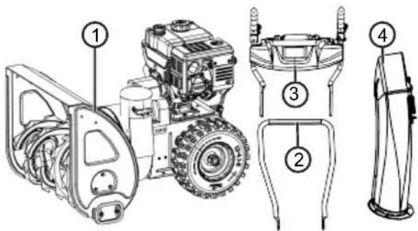
2.4 KomnJIeK T nocTabKn 620 E III
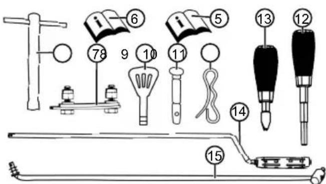
KOMnJIeKT NOCTaBKN BKnIOucaET B Ce6a nepeuNcJIeHHbIe N03uCIN. IpoBepNTb, BKnIOUeHbI JN BCE N03uCIN:
3anpeaaetc6paTbcs 3a uHeKOBbI TpaHcnpTeP n He HAcTyNaTb Ha Hero!

Ipejde yem BbINOnHnTb pa60Tb Ha ycTpoNCTBe, CneDyEt rnyuHTb DBnraTeNb.
Ipejde yem BbINOJIHrTa pa6OtblnoTexnueckomy 06cnyKBAHHIO npMOHTy, CneJyET CHMaTb KOJaauOK cBeu 3aXnraHnI
BbIeNTe NoCTOpOHnX IuC n3 O-nachOy 30HbI!
BpaaouieceyactnB30he pa3- rpy3kn!Onachoctb 3atraHbAHn!
2.5.2 CmboJIbI 3KcIIpyaTauN
CnmboJ 3HaueHne
PbUar noKaUKN CLOSE / OPEN (3a-KpbITb/OTKpbITb)
Ta3 MeHHeHHo/6bICTpo
MoToPbI KIOU BKn./BbIKn.
ToNNBHykpan OFF(BbIKn.) ON(BKn.)
KhoNka Hacoca noKaUKN


CnmboJ 3HaueHne
UepBnHbI npNBOd Nyck/OctaHOB

KonechbI npBOD Nyck/oCTaHOB


COBMeCTNTbJKeIIO6 BByrpy3KN CHERaC pyKoRTKOI
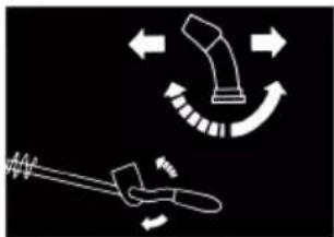
OtperynipoBaTb BblcotyKeNo6a BbIrpy3KN Chera C NOMoubIOpbuara
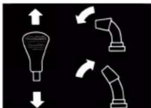
2.6 O63op n3denn 620 E III (01)
B ob3ope n3delen (01) npuVeDeHa o6uaa NH-ΦopMaζησ Μb yCTpOιcTBe.
YcTpoIcTBo pa3peWaaetc8KcNpyaTnpOBaTb TOJIbKO B NOJIHOCTbIO yCTaHOBJIeHHOM COCTOJHIN!
Ipeed BKIOUeHEm CJeDyeT npOBepaTb HaIINuHne N IcnpaBHOCTb BCEX npEdoxpaHITeJIbHbIX N 3aUNTHbIX yCTpoiCTB!
Heo6xOaIMbIe INHCTpyMeHTbI
Ho- uHcTpymeHTa Mep
1 RaeyHbI KIOU C OTKpbITbIMn NIN 3a-KpbTbIMN 3eBaMn SW 10 (2 wT.)
2 Raeyhbl KIOU COTKpbITbIMN 3a-KpbITbIMN 3eBaMn SW 13
3 TopoBbI WeCTnIgpaHbI KIOU 5 MM
4 UnncbI nn nnHHoruy6cbI
5 OTBepTkα
6 INHcEKTNuHoe MaJNo
7 Hacoc nla HaKaunBaHnI mH c MaHoMeTpom (Knaanu Wpaepa)
5.1 MoNTaX HIXKHeRo 3JIeMeHTo pyKOaTKn (03, 04)
YCTaHOBtB HIXHn 3JemeHT pyKoTKn BHN3y CJIeBa n Cnpaba OT ppe3epHoro CHeroOuHcTnteJIa.
-
BbIKpyTNTb BnHTbl (03/1).
2.ПркpenHнЖнйэлм ent pyKoTkn (04/1). -
BCTaBnTb BnHTbI (04/2) B HnXhN IJIeMeH T pyKoRtKn N 3aTAreHyTb.
5.2 MoHTax naHEn ynpaBHeHHa (05)
- JEBBI HIXHNI 3JIeMeHT pyKoTKn: Ocna-6nTB 2 60nTa (05/1) Ha KpeNEXHOM yroJKe (05/2) n ChrTB KpeNEXHbI yroJOK.
2.ПркpenTb BepxHn 3JeMeHT pyKoTkn (05/3)c nHeIbU ynpaBHeHn. - Праьы Верхни селем ent pykoarTKn: BcTaBntb 260JIta (05/4)В Верхни n HuxHHN 3- JIeMeHT pyKoARTKn N 3aTAYb INx NOdklaHbIMN Wai6amn n raikamn.
4.Левий Верхни лем ent pykoRTkn:Всты 260лta (05/1)В Верхни И Нжни 3- Лем ent pykoRTkn IN Kpenexньуrolok IN Cпгka 3aTaryt b nx NOdknaHbIMn IaMбam n raikamn.
5.3 MoNTaX upeYlnpObaHne TopMo3HbIX TpocOB IJI KONECHORO u CepBraHORO npIBoDa (06-11)
1.ПовьсиТБ Topmo3Hо Tpoc (06/1) колесно npвoda (06/2) на Нж-hee OTBepCTne (06/3) npaboro pbuara.
2.ПОДВЕСТБ TOPМОЗн TPOC (07/1)ЧЕРBAч- HOrO npINbOda (07/2)Ha ВерхHee OTBepCTne (07/3)Левoro рьчara.
3. OTPerynipoBaTb TopMo3HbI TpOcbl CneDyUo- uM o6pa30m:
I NobopauNbBaTb peryunpoBOUHyO deTaJIb TOpMo3HOro TpOca (08/1) B HnPaBHeHn CTpeKN (08/a), Noka TOpMo3HO Tpoc He nepeCTaHET npOBuCaTb (6yTe CnerKa HATaHT). Bo Bpem BaPaeHn DEpXaTb TpOCOBYIO TAY TaK, UTObI OHa He cKpyuNBAJacb.
3aTMyTb (08/b) KOHTprAky (08/2).
- 3akpenntb TopMo3Hbe Tpocbl (09/1) 3axmamn (09/2) cneBa n cnpaBa ot pykoTkn.
- HatakeHe TpoMo3Horo Tpoca:
Ocna6ntb KOHTpraKn (10/1, 11/1).
I NobopaunBaTb pe3b60BoH hakoHeuHnK (10/2, 11/2) BBepx, noka TOpMo3HoTpoc He 6ydet HataHyT.
IIOBepHyTb KOHTprAaKn npOTNB HAnpaBJIHOUsEi (10/3, 11/3), UTo6bl 3aФнКсрOBaTb TOPMO3HOn Tpoc.
- Notaryb pe3HHOByU 3aRnyuKy (10/4, 11/4) BHN3 Do KOHTprAyn (10/a, 11/a), yTo6bl 3a- uNTnTb TOPMO3HO Tpoc OT Koppo3nn.
5.4 PerylnpoBaHne TopMo3Horo Tpoca (12)
TouHoe perynipobAHne npOn3BOJNTcpeynipoBOHyBIM 60TOM.
-
Ocna6ntb (12/a) KOHTpraIky (12/2) Ha peryI npoBOvHOM 6oNTe.
2.ПоворачиВаТb(12/b)perулровьнь 6oNT (12/3),чTo6bl yДиHHT b nIy yKOpOTnTb XoT TOPMO3HOrO TpOca.Y6eДntbCЯ,чTO TOPMO3-HOH TpO CJIeRka HATaHyt n He npOBuCAeT. -
Choba 3aTaryb (12/a) KOHTpraKy (12/2).
5.5 Поберka Habстpoи Topmo3Horo Tpoca (13)
Topmo3HO Tpoc KOlechoro npBODa co BpeMeHem ydnnHareTc. Ecni KOleChbI npBOD 6oNb-We He BKIOUaETc npi paOtaIOuEeM DBNrataTeNe, Topmo3HO Tpoc CTaJ CnIshKOM DNIHHbIM Nero Heo6XoDIMO NOdTaHyTb.
- BbIKHIOHTb yCTpoiCTBO (cM. aJaa 6.8 "TnyuHue deusamea (37, 38), Cmp. 341).
- OTPeryu npobatb TOpMo3HOn Tpoc (cM. 2Jna8a 5.3 "MOnmax u peayu npoeaHue mOpMo3HbIX mpoc0e dny KonechO2o u uepeyHoo npu- oeda (06 - 11), Cmp. 337).
UTo6bl npOBepntb HAcTpoNky TOpMo3HOro TpOca:
- 3aBecTn DvIraTeJIb (cM. aJa8a 6.7 "3aSeDeHue deUaMeJra (31-36), Cmp. 340).
- BkIIOuHTb nepeJaCy (cM. aJaa 7.1 "3anyck peKuma ouucmku (39 - 41), Cmp. 341).
- MeДленHo haxmMaTb npaByO pyky (13/1) KOJIeCHOro npINBOda BHN3 (13/a), noka He no- cyBCTByeTe JERKoe cOnpOTnBNeHne.ToUka HaxKatna CcENHeHn ONpeDeneHa.
- Ecni KonechbI npnBOd He BKInOueH: NOBtOpuTb npdeBldyUne 7arn.
- EcnH He ydaNoCb OTperyInpoBaTb Tpmo3-HoTPOC: O6paNTbcB B cepBnchbI cHTp N3rTOBnteJIa.
5.6 MoNTaX TAYn pbIyara nepeKJIoueHn nepeDaU (14, 15)
- 3aueHb Tary (14/1) 3a KpoHsTeH npeKluOeHn nepeDaU (15/2) Bn3y.
- 3açenntb Tary 3a kpoHtTeH pbIyara nepeKlIOueHn nepeJaU (15/3) BBepxv.
- 3akpeinb Bepx Hn3 Taryn NOknaHbIMN shaibamn npyknHHbIMn fNKcaTopaMn.
5.7 MoNTaX pbIyara Bbl6opa nepepaN BBICOTbI Bblrpy3Kn (16)
- ПпкрпNTь пужнньie sha6by (16/1)Ha pe3b6e.
2.ПиВИNTITb 3aTЯHyTb pyIar ДЯ рERYIPOBAHIN BBICOTbl BByrpy3KN (16/2).
- ПпвHTиТь n 3aTЯнТь рыuar Вьбopa nepeDAu (16/3).
5.8 NpokJIIOUeHne uTeKepa cnCTeMbI OToONJIeHnN IOdCBETKn (17)
1.Поdkлочьчсишт ekepа(17/1)cnteMbI OToPJIeHnI NpOcBETKn.
2.3aTMyTb uTeKepeHoe coeDHeHHe.
5.9 MoNTaX XeIIO6a BbIrpy3KN cHera (18 - 21)
- Cnerka cma3aTb cKoJIb3aIyU IOBepXHocTb (18/1) JeNo6a Bblpy3Kn Chera fpe3epHorO CHeroOuNCTnTeJ NHCeKTnUdHbIM MaclOM (IIIN cMa3KoJ).
2.ПодсоeДинИь(19/a,20/a)желб ВыгуЗк chera(19/1). - ПрodeТь кренихные 60NTы (20/2) ИЗнутп uepe3 habравлишке Кроншейны и Лобь Bыгтузк сera.
4.ПиВИNTITьжелб Вьгрузкс Chera c nOMO-цьюcamOKOHtrpuauxcraek(20/3).
5.BCTaBtB KpeNexHbIe 6oNTbI (21/1)Yepe3 6oNbSyU HnPaBnJIoUyIO nlaCTnHy (21/2) IN npKpeNITb MaIyO HnPaBnJIoUyIO nlaCTnHy (21/3). Ipumeyue:MaJIeHbKaHa nPaEJaoua nnacmuHa doJxHa haxodumbcra noepx 6oNbwo. - BCTaBntb HappaBJIauOuIe IJIaCTnHbIC Kpe- neXHbIMn 6oJItAmn B XeNo6 BByIrpy3Kn Chera CHN3y.
- HanaTb nodknAaHbIe 1aai6bl (21/4) Ha 6oTbI.
8.ПлOTно 3aTЯнтьcamOKOHТРЯшпеся raйки (21/5).
5.10 PnncoeDHeHne TOpMo3HOro TpOca K pa3rpy3OuHomy KnaNaHy (22)
TOT TOPMO3HON TPOC Nepemeaaet 3acNOHky XeI06a BbIRpy3KN CHERA INcNoJIb3yETcIЯ peRyIINPOBAHNA BBICOTbl BbIRpy3KN.
1.Повспьtopmo3нОТpoCHaHanpaBJIIO- 乌(22/1,22/2).CneуET npKpeNTb K Topmo3HOMy TpOcy pe3HOBYIO 3aInyuKy.
2.ПлOTноЗakpyuNbBaTb KOHTprAry (22/3,22/4) npOTnB HApPabJIIOUeN (22/2), noka TOpMo3-HoH TpOc He 6yDet HATaHyT.
Kakdbie 8 yacob pa6oTbI
CneDyeT CMA3bIBaTB WHEKOBBI TpaHCnOpTep.
Kakdbie 3 Mecya
CneNyET npOBepaTb daBnHe B03dyxa B uHHax.
Cma3bBaTb KOIbO JeIIO6a BByIpy3KN CHERA INHCEKTIUNIDHBIM MacnOM.
pa3B roD
CneJyET 3aMeHЯb CBeUy 3axnraHnA (cm. pyKOBOcTBO DnRaTeJI).
CneNyET Cma3bIBaTb WHeKOBbI TpaHCnOpTep.
CneNyET 3aMeHrTb MOTOpHoe MacNo.
9.2 Cma3bBAHHe IHEKOBORo TpaHCnOpTepa (45)
BbIaBHTb npImepH0 2-3 nopun yHnBepcaIb-Ho CMA3KN B CMA3OHyB HnPpeIb (45/1) c noMoUb CMA3OHyHO Unpuca.
9.3 KonechbI n cepBryhbl npBOD (08)
PNEpyPExEHNc!OnacHocTb TpaBmnpoBaHn BO Bpem TaXObcnyKuBaHn. He npaBnIbHoe TexO6cnyKuBaHne MoKeT npuBeCTN K cepbe3HbIM TpaBMam I NOBpeJdeHIO yCTpoi-CTBa.
PerynipoBaTb TopMo3HOn Tpoc ToJbKO npn 3aBeDeHHOM DBNrTaTeJe.
3arnyuHTb DnurTaTeNb,ecN KonechB/YepeBryHbI npuBOd He OTKnUOaETcR.
3anpeuetaetc peMOHTnpoBaTb erO caMoCToTeJIbHo.CneIyET HemeIeHHO o6paTntbcB A aBTOpN3OBaHHoe npeInpnTne.
I IINMEUAHNE Bnara B TopMO3HOM TpOce MOKeT pInBeCTN K Koppo3n INI 3aMep3aHIO. IOBpeXeHHbI TOpMO3HOJ Tpoc Heo6xOdIMO 3aMeHHTb.
OTperpylnpoBaTb TopMo3HOn Tpoc
Ecn npa6oTaHcem Dnuratene HeBO3MOxHO BKNUHTb KOleChb/YeRbHbI npuBOd, Heo6XODIMO OTpeRyInpOBaTb COOTBeTCTByOuN TOpMO3HO TPOC.
1.Ocna6ntb KOHTpraKy (08/2).
2.ПоворачиВаь PerулрОвоHуДeТаь Topmo3HOrO TpoCa (08/1)Внанравлели CTpeIkn (08/a),пoka TOpMo3HOn TpoC He nepeCTaHET npOBuCaTb (6yTe CJIeRka HATaHyT).Bo Врм Bрашени Держath TpoCoBvI IO Tary TaK,чTo6bl OHa He ChkpyuBaJacb.
3. 3aTaryb (08/b) KOHTprayky (08/2).
4.Утобл поверпь Habстpoиу,За vectи DBI- ratelь И BKIOHHTb KOJIeCHbI/ЧepВЯчын npINBOd.
5. Ecni KoIeChbIyUepBryHbI npBOD no- npexHemy He nOlyuayetc 6e3oNaCHO BKnIOyAtb N BbIKNIOyAtb, yCTpOiCTBO Heo6XoIMO DOCTaBNTb B CneuaJIN3nPOBaHHbI cepBNC.
9.4 3aMeHa cpe3HbIX uTnΦTOB (30, 46)
B ueJx 6e3onacHocTn onepaTopa n yctpoicTba cpe3hble uTnΦtbl (30/1) moryt o6opBaTbcn noCne 6nOKIpOBKn UHeKOBOr TpaHCnpTepa.
8 NPMMEUHNE O6OpBaHHbIe cpe3HbIe 7tNcTbI CJIeDyET 3aMeHrTb Ha OpuHHaJIbHbIe. IcNoJb3OBAHHe HeyTBepKdEHHbIX 3aNuaCTeY-CTPOICTBO MOKeT PnVBecTI K cepBe3HbIM NOBpeKdEHnM yCTPOIcTBA!
- BbIKHouHTb yCTpoIcTBO, n HaTeB KOJINaOHCKeHu 3aXnHaHn.
- ChTb (46/a) npyKHHHbI qNKcaTop (46/1).
- BbHyTb (46/b) NOBpeKdEHHbIe cpe3HbIe UTnΦTbI (46/2).
4.Проверпь Вал Ha npeДмТ NOВржден. - BCTaBnTb HOBblc Cpe3HbIe WITnΦTbI N 3akpe-NTb npyKHHbIM qNKcaTOPOM.
10 YCTPAHEHNE HENCPABHOCTEIN
OCTOPOXHO! Onachocb TpaBMnpoBaHn.Двжушеся чаTNи DeTaJI N OcTpbIMKpaAMMOrT npVBeCTN K TpaBMam.
Bcerda Hocnte 3aunTHbIe nepuATKn BO BpeMraTexHnueckoro 06cnyKnBaHn, yXoJa n O-uctkn!
3arnyuinte Dnuratelb n y6eintecb,TO OH octaHOBNJcra!
BbHMaIte KOnnauK CBeu 3axnraHn!
8 INPIMEYAHNE B cnyuae BO3HNIKHOBEHn HEnCnpaBHOCTe, KOtOpbIe He yKa3aHbI B DaHHoT Ta6Nlue NJI C KOTOpbIMN Bbl He MoKeTe CnpaBNTbcr CaMOCTOReTbHo, ObauaNTecb B HaUy cepBnCHyO cnyx6y.
| HeinspanpaBnOcTb CnOco6bI yCtpanHeHn |
| ДвигателоварobTaet. 3aJIntb 6eH3nH. |
| YCTaHOBInb рычаг ra3aВ пОLOJKeHne Start (ПусК). |
| ВклIOчINb рычаг поkaч- KN, ВкIIOчINb HAcOC по- KauchN. |
| БыIpONHInb TexO6cnyx- BaHne CBeyn 3aЖИraHnY. |
| СнжЕннaj MOUChOcTb DBN- rataTeЯ. OuNcSTnTb pa3rpy3Oчьй kaHaJI nII N KOpNyc. |
| УдaJIntb ChERи ЛeД coш- HEKOBOrO TpAHCnOpTepa И MeTaTeIbHOrO KOleca. |
HecnpapBHOCTb CnocO6bl ycTpaHeHHa
www.al-ko.com/service-contacts
14 TAPAHTNIA
Mbl yctpaHReEM BO3MOXHbIe DepeKtbl MaTePnaIOB nII npOn3BOIDCTBa B TeueHne cPoka daBHocTn, yCTaHOBJIeHHoro 3aKOHOM B OTHOSeHn peKNaMaucn NO KaYeCTBy, nyTeM pEmOHTa nII 3aMeHbI n3DeJn. Cpok daBHocTn onpeJeTcra 3aKHOdaTeNbCTBOM cTpaHbI, B KOTopoN 6blno npNo6peTeHo y-CTpoiCTBO.
Hahe rapaHTnHoe o6aTeNbCTBO DeIcTBnTeJIb- rapaHTn aHHynpyTc npi:
HO TOJIbKO npN:
CobIIOdaIte daHHoe pyKOBOcTBO no 3Kcnnyatau
HaandekaaemObpaehn;
NcNoIb3OBAHnOpuHaJIbHbIX 3aNaChbIX ChaTei.
cAmOCTeTJIbHbIX NOnbITKaX pEmoHTa;
cAmOCTeTbHbIXTexHnueCKNXn3MeHeHHx;
ICNPOJIb3OBAHnHE NO Ha3HaueHnIO.
TapaHTnHa He paCnpocTpAneTcRaHa:
IOBpeKdEHHaKOKpaCooHOro NOKpbITn, Bbl3BaHHbIe HOpMaJIbHbIM n3HOCOM;
N3HaINBaIOUeC8 YAcTn, O6O3HaueHHbIe B BeDOMoCTN 3aNaChbIX YAcTei paMKoX XXXXX (X).
BnraTeHn BHyTpeHHero cropanna (Ha Hx paonpoctpaHIOCTc rapaHTnHbIe nOJOKeHn COOTBeTCTByUoIero npOn3BOIDTeJI).
FapaHTnHbI cPOK hauHnaETcN oCNe NOKyKNi NepBbIM KOHeuHbIM NOJb3ObaTeJIeM. OnpeJeIoumI
ΦaKTopoM cnyknt dAta Ha DoKymHe, NoTBePjDaIOUeM NOKynKy. ObpaaIaTecb C HAcToaIIM
cepTnΦnkATOM I DOKyMeHtOM, POnTBePjDaIOUeM NOKynKy, K CBOeMy DNJIepy INI B 6bnKaIshn AB-
TOPn3OBaHbI CepBnCHbI cEHTp. HAcToaIIN cepTnΦnKaT He KacaETcR rapaHTnpyeMbIX 3aKOHOM
IpaB Ha npTeH3nn NOKyNaTeJI K npOdaBuY.
IPEKJIAD OPINIHJY NOCIBHnKA 3 EKCIIyATAUII
3mict
1 Inopmaia npo noci6nik i3 ekcnnyata- 347
1.1 CmboJn Ha TtTyIbHi cTopiHci..... 347
1.2 YMOBHI No3HaueHHa Ta CnHahbHi cNoBa... 347
2 Onic npuctroo 347
2.1 BnKOpncTaHHa npH3HaueHHaM..... 347
2.2 MoxJIInBe nepeI6aueHe BnKOpncTaH Hr 347
2.3 3anobixhi Ta 3axnchi eIeMeHTn..... 347
2.4 Komnnekt noctaehna 620 E III 348
2.5 YMOBHI nO3HaueHHa npicTpOIO.... 348
2.5.1MiTkn6e3neKu 348
2.5.2 CnmboJI n ekcnnyaTauii 349
2.6OrnayBvpo6y620EIII(01) 350
3ПравILA texHikn 6e3nekn 350
3.1 Bka3iBkn 3 Texhikn 6e3neKn 3riJHO 3 ISO 8437 DoDaTOK A 351
3.2ПравILAТexhikn6e3neknpiДчac BИКОРИСТAHн.. 352
3.3 NObOJKeHHa 36eH3nHOMiMACJOM..353
4 Po3naKOByBaHH npncToIO (02) 354
5 CknaaHn.. 354
5.1 MoHTax HnXhBoi nonepuHn (03, 04) 354
5.2 MoHTaK nAHeJI kepyBaHHra (05) 354
5.3 MoHTaK Ta peryIIOBaHnHa 6oyDeHIBcBKnX TpOciB dJa KOniChOro Ta nPa-3yHOBOr npuBoiB (06 - 11) 355
5.4 TouHe peryIIOBaHHa 6oyDeHIBcBkoT Tpoca (12) 355
5.5 IpeBipka peryIIOBaHHa 6oYdeHIBcBkoT Tpoca (13) 355
5.6 MoHTaK TAYn BaxKeJy BvBOpy nepe Daui (14, 15). 355
5.7 MoHTaX BaKeJЯ Bn6Opy nepeaui Ta BnCOTn BnKnDaHHra (16) 355
5.8Пикюechняшт ekepa cncTeMn ona- neHHra Ta niDCbITkn (17) 355
5.9 MoHTaX JxOJIO6a BnKuIaHnHa Chiry (18-21) 355
5.10 KpiinneHn 6oyeHiBcBkoTpoCaHa Kpuu jkoJIo6a BnKnDaHHa (22) ....356
5.11 MoHTaX pyuKn dIypeRyIIOBaHHJ Ko- no6a BnKndaHn CHiry (23) 356
5.12 HabiuybaHHa 6oydeHicbkoTpoca (24) 356
6 BBeHeHH B ekCnIyatauio 356
6.1 PAnBHO-MaCTnBHi MaTepiA.. 356
6.2 3aJIbBaHHa MoTOpHoI OJINBn (25).....357
6.3 3aJIbBaHH8 6eH3nHy (25) 357
6.4 Npebipka Tncky B uHax (26) 357
6.5 PeryIIOBaHHB BnCOTn po6OTn (27- 29) .357
6.6переверка зримхболтib Ha npn- cTpoi (30,46) 357
6.7 3anyck DnBnyHa (31-36) .358
6.8 3ynnHa DnBryHa (37, 38) 358
7 Ekcnnyataua 359
7.1 Nocatok po60tn (39-41) 359
7.2 PpnnnHn np6oTu (42) 359
7.3 3MiHa nepeaui IJIy KOJicHoro npuBoDa (41-43) 359
7.4 YcyHeHHa3kyOpIOBaHHxOio6a BnKDaHH Chiry (42, 44) 359
8 PemOHr 359
9Texhiue o6cnyroByBaHH Ta dOrrnld 360
9.1 Tpaqik TexHicHoro 06cnyroByBaHHra.. 360
9.2 3MaJIeHHa WHeKOBOrO KOHBeεpa (45)360
9.3 TexobnyroBvBaHnKaKoiichoro Ta npa3yHOBOrnpINBoDIB (08) 360
9.4 3aHa 3pi3Hnx 6oJTIb (30, 46) 361
10 YcyHeHH HeCnpaBHOcte 361
1136epirahnna 362
12 Ytuniana 362
13 Cepbiche obcnyroByBaHHra. 362
14 Tapahtia 362
1 IHΦOPMAUJII IPO NOCIBHNIK I3 EKCPIYATAUII
Himeuzka Bercia miCTnb opurihalbni noC6nK i3 ekcnnyatauii. Bci iHwi MOBHi BepciI ue nepeknadn opurihalbHoro noci6nka 3 ekcnnyatauii.
3aBxDn TpMaIte uei nocibnk i3 ekcnnyataii niD pykoU, uOb npouHTaN Ioro, kUo BAM 3HaOnobTbcra IHopmaia npo npncTpi.
IpeepaBaiTe npucpii HnM o6bAm Tlb- Kn pa30m 3uM nocibHKoM i3 ekcnnyataui.
IpouHTaTe Ta DotpmyntecBbKa3iBOK 3 texhikn 6e3neKn Ta nonepedKeH, 0o MicTAYbcra B cboMy nociHnky 3 ekcnnyataci.
1.1 CnmboHa THTyIbHi cTOpIHci
CmB0J3HaueHHa

O6OB'3KOBO npoHTaTe uei noC6HnK i3 ekCnnyatau i nepeB BBe-DeHHaM BekCnnyatauio. Lc e He06XiHO yMOBOO 6e3neuHOI Ta 6e3BIDMOBHOI pObotn.

NociHnK 3 ekcnnyataaii

He BnKOpNCTOByIte 6eH3uHOBn npnstpii no6n3y BiDkPntoro noJym'a6o dKepeI TeIIa.
1.2 YMOBHnNo3HaueHH Ta CnHnBHi CIOBA
HE6E3NEKA! Bka3ye Ha He6e3neuHy cnTy-aizio, yka, kso II He yHnKHyTu, npn3BOaNTb Do cMepti afo cepno3Hx TpaBM.
NONEPEDXEHH!Bka3ye Ha noTeHciHNO He6e3neuHy cnTuayio,ra,kUo II He yHNKHTn, MOKe npn3BeCTn Do cMepti afo cepno3Hx TpaM.
OBEPEXHO! Bka3yE Ha noTeHcuiHo He-6e3neuHy cnTuayio, yKa, kKIO II He yHNKHyTN, MOKte npN3BecTn TpaBMvBaHHaJeRKOi Ta cepeD-HbOI TAAKKoCTI.
YBAGA! Bka3ye Ha cnTyauciIO, JaKa, KaUO II He yHnKHyTN, MoKe npN3BeCTN Do MaHOBOrO 3bNTKy.
9 PnMITKA CneiJIbHI Bka3IBKn dIg Kpa- 100o po3yminHra ta noJeHHeHH po6OTn.
2 OINC INPNCPOHO
2.1 BnKOpncTahHra np3HaueHHaM
Φpe3epHn CHirooUChN Kpni3HaueHn BnKJNoHO nI np6npaHH N0iHo BNNaBwOro, MOKporo nnnykoro CHr 3 yKpinJIeHnx Dopir Ta DiJnHok, HApnKnad, BHyTpiHix DbOpNKIB, NiD'izDn RaPaxa, TpoTyapIB a0 npKyBaJIbHnx Micu, To6To dIy npNBathoro BnKOpNCtAHn. DopiXKn Ta DiJnHKn, 0o MaOTb ByTN OUYneHi BiD Chiry, NOBHN Hi Matn MiCyO HcOHOy Ta pIBHy NOBepxHIO, HApnKnad, MoSeHHraTeOHHO, rpaHIthOIO TpoTyapHOIO NNITKOIO YN acFaIbTOBe NOKpTTT.
Ley npncptpi npn3HaeHO nI npBaTHORo BnKOpnCTaHH. ByIb-Ke iHwe BnKOpNCtAHN a6o HeCAHKIOHOBAHI 3MiHn Ta DOONBHeHH KOnCTpyKcII BBaxaIOTBc BnKOpNCtAHHM He 3a npn3HaueHNi I npn3BOJrTb Do aHyIOBaHH rapaHTi, a TaKoX BTPaN BiIDNOBIDHOCTi Ta BiIMOBN BiD 6yDbKaOi BiIDNOBIDAhHOCTi BnPo6Hnka 3a WKOy, 3aBDAhy KopncTyBaueBi a6o TpeTl CTOPOHi.
2.2 MoxJIbIe nepe6aueHe BnKOpncTaHHa
LeyΦpe3epnHn CHirooUncnK B npn3haeHn I nI npn6npaHn CHiY 3 HeyKpInneHnx Dopir i dI JnHOK, HApNKnad, i3 rpaBimHM, Ue6eHeBm a- 60 pocnnHHM NOKpTTam (ra3OHIB). Ley npnCTpiH He npn3HaueHn DnA npn6npaHn BeJIHKoI KIIbKOcTI CHiY, BUCOKNX KyUyp, DyJx MOKporo a60 BTPaM6ObaHO CHiY, a TAKOX NbOdy.
Pnucpii He npn3NaeHm dIa KomepuHoro BnKOpNCTaHHB rPOMAdcbkNx napkax,Ha cNoptNBHNX MaJdaHnKax, y ciNbcbkOMy Ta JicOBomy roCnoDapCTbax.
2.3 3anobixhi Ta 3axnchi eIeMeHTn
NONEPEJXEHH! He6e3neKa TpaBMyBaHH. HecnpabHicTb abo BiDcyTHicTb 3an06iKHNx Ta 3axnCHnx eJeMeHTB MOKyTb npn3BecTu Do cepno3Hnx TpaBM.
HecnpabHi 3anO6iXHi Ta 3axnChi enemHTN cnid BiDpeMOHTyBaTI.
YxOJHOMy pa3i He BnBOJbTe 3 NaIy 3aNO6ixKHi ta 3axnChi enemEnTn.
Baxijb 3yenJenneHH
PykoTka KepyBaHH npucTropo Ma c Da Ba BaxeJI 3uenneHH. Y pa3i He6e3neK Tpe6a BiDnyctHTN 0bndBa BaxeJI 3uenneHH.
Baxinb 3uenneHHn dny cepB'ayHoro npNBOda kono6a BnKndaHHn chiry. YepB'ayHn npNBOd 3ynnHaeTbcra.
Baxinb 3yennenHnIyTAROBOro npBOda. TaroBn npBOD 3ynHnEcTbcra.
Kono6 BnKnDaHHa Chiry, 00 perynoeTbcra
BcTaHOBIb JKOIOb TaKIM YINOM, 06 CHIR, 00 BKNIaCTbcR, He 3aIrpOxyBaB IIOJAM, TBapINHAM, 6yIDIBNAM, TpaHCnOpTHm 3acobam ToIO. DToPnMyIteCg OBepeXHocTi, 06 He nepeWkoJxatn pyxy i He HapaXaTn Ha He6e3neKy iHux yachNIKIB DOpOxHbOro pyxy.
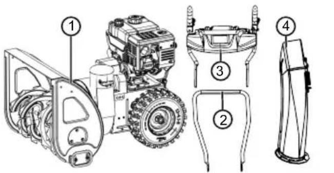
2.4 Komnnekt noctaun 620 E III

KomnneKT noctaHnMa MiCTb nepeJIyHeHi no3nCi. II. NepeBipTe HaraBHicTh BCix no3nci:
| Ho- Мер | Комнонец КOMПОНЕТа |
| 1 Φразец 2 Ножни постеси 3 Паель уравлипя 3 ворхим[eльмен- ТOM рукib'я 4 Кожоб ВикIDsанни сhiу 5 Посібник 3 ekсплуатацii Фразец 6 Посібник 3 ekсплуатацii двигуна 7 Komплеск Кріпенья колоба Вик- данни сhiу (3 sht.) 8 CBИЧКOBИ KЛЮч 9 Клиоч жИВлени ДВИгуна (2 sht.) | |
| Ho- mep | KOMNOHEHTa |
| 10 | 3apachni 3pi3nhi 6oItni (4 shT.) |
| Сумka 3 TakuIMN KOMNoHENTAMN: | |
| 11 | Пружинни ФikcaTop (4 shT.) |
| 12 | ВaxiNb BucOTn BvKnDaHnY 3 npy- xinHHM KijbUeM |
| 13 | ВaxiNb Bv6Opuy nepeDAu 3 npyKinH- Hm KijbUeM |
| 14 | Тяга ВaxeJЯ Bv6Opuy nepeDAuY |
| 15 | Ручka Дли рergunobAHнь ВиknDaHnY |
2.5 yMOBHI no3HaueHHa npncTpoko
2.5.1 Mitkn 6e3nekn
BaxiNb nidaKaUyBaHnA CLOSE/OPEN
KlnuJXnBJIeHHa DnIryHa yBIMK./BMMK.
Koicn npBOD
Iyck/3ynHka


BupiBnIte KOno6 BNKndaHn CHiry 3 KpBONIWOM
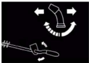
BiDperyIIOTe BnCOTy BnKndaHn Chiry 3a DOnOMOrO IO BaxKeJI
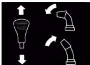
2.6OrnBnpo6y 620 E III (01)
Даи habeDeHo orJЯn npicTpOIO (01).
Heo6xIDHn iNCTpyMeHT
HoMep
IhCTpyMeHT
1 Pikkobni a6o haKnHn KInOu Ha 10 (2 wT.)
2 Pikkobn a6o HauDn Kluu Ha 13
3LecTnrgpaHHN KJIIOU 5MM
4 Placatnki y n npockory6ci
5 BukpyTka
6 MaCTnJIbHnIe
7 Hacoc IJIaIsh i3 MaHOMeTpom (ABTOMO6JIbHNI KJanaHa)
5.1 MoHTaX HxHbOi nonepeuHH (03, 04)
YctaHOBt b HxHIO nonepuHy JIBOPuy i npabOpuy BiD qpe3epHoro CHIROUCHNka.
- BnKpyTItb rBnHTn (03/1).
2.Прикпіпітьнхню порechу (04/1). - BctabTe 60ntn (04/2) uepe3 HxHIO nonepe- uHy i 3aTgHiTb.
5.2 MoHTaK nAHeI KepyBaHHa (05)
- JIbA HIXHЯ nonepuHa: Nocna6Te 2 rBnHTN (05/1) Ha MOHTaXHomy KPOHsTeHi (05/2) i 3HIMITb MoHTaXHm KPOHsTeHi.
2.ПикpiniTbВepxHn eIeMeHT pyKIB'Я (05/3)do naHeni KepyBaHHa. - Правий Верхшиеlement pykib'я:Встав'te 2 60ЛТN (05/4)у Верхню та Нжню поелении i 3aTЯгпьixNiДКладимMuшayбамTu raikamn.
- JIbH BepxHi eemeHT pyKIB'ABCTaBTe 2 60NTn (05/1) y BepxHTo Ta HIXHIO nonepuHN Ta MOHTaXHH KPOHHTeH i 3JIerKa 3aTgHITb IX NiKJaADHMM ShaBamTa raIKaMn.
5.3 MoHTaX Ta peRyIIOBaNHn 6oydHiBCbKx TpOcIB dJa KJIichoro Ta nJa3yHOBOro npNBoID (06-11)
1.ПдВicbTe 6oydeHicbKm Tpoc (06/1) konic-Horo npNbOda (06/2)Ha HnXhI NOrBip (06/3) npaBOro BaKeJy.
2.ПдВicbTe 6oydHiBcKn Tpoc (07/1) npa3yHOBOrO npuBoDa (07/2)Ha BepxHn OTBip (07/3) NiBOrBaXeJIa.
3. BctaHObitb 6oydeHicbki Tpocn k3a3HaueHo:
I NobeptaTe peryIIOBaIbHy yactHy 6oydeHicBcKOro Tpoca (08/1) y Hanpymky cTpiKn (08/a),doKn 6oydeHicBcKn Tpoc 6iNbSe He npOBuCaTmE (nerKe HataXiHn).PiJ qac nobepTaHHr TpmaHTe Tpoc, 0o6 Bin He nepeKpyuBaBCra.
KoHTprayky (08/2) Tpe6a 3ataryHyTu (08/b).
- 3akpiinTu 6oydeHicbki Tpocn (09/1) 3aTnCKaamn (09/2) nibopyu i npabopuy BiD pyKIB'a.
- Hatr8 6oydienbcko Tpoca:
BiDkpyiTb KOHTpraKn (10/1, 11/1).
O6eptaIte pi3b6obn haKoHeuHnK (10/2, 11/2) Bropy,doKN 6oydHiBcKn Tpoc He 6ynde HataHyTo.
O6eptaTe KOHTpraiKn npOTn HaprMaHOI (10/3, 11/3), 0o6 3aΦikCyBaTn 6oydHiBcBKn TPOC.
- ПOTЯгнтугмову заглuyшky (10/4, 11/4)do KOHTpraykn (10/a, 11/a), zuob 3axnctntn boy-DeHicbki Tpoc BiD Kopo3ii.
5.4 Toyne perynobHHa 6oydeHicbkoTpoca (12)
ToHpe peryIIOBaHHa 3diINCHIOCTbCra 3a donOMoTIO peRyIIOBaIbHO rBnHTa.
- Послаб Te (12/a) Контразу (12/2) на ретювалову homу 6oNTi.
-
06eptaTe (12/b) perynobbHn 6oT (12/3), uO6 noDobKHTn a6o ykopOTn xiD 6oydHiBcBKOro Tpoca. NpekoHaTnc, uO 6oydHiBcBKn Tpoc Tpoxn HATrHyTn i He npOBuCaE.
-
3HOBy 3aTayHITb (12/a) KOHTprAky (12/2).
5.5 IpepeBipka peyIIOBaHnHa 6oydHiBCbKOro Tpoca (13)
3 yacom 6oydeHicbKn Tpoc KOnichoro npnbOda po3Tayc. RaKIO npn npauoohomy DBrnyi KOJICHN npNbOD BKe He BMNAeTbc, 6oydeHIB
CbKn Tpoc CTaB HAnTO DOBm i NOrO CJIiD HATyHHTN.
- Bumkhitb npncpti (nB. po3di 6.8 "3yunka deuyha (37, 38), cmopiHa 358).
- 3HOBy BiDpeRyIIOHe 6OyDeHIBcBKn Tpoc (nVB. po3di 5.3 "MoHmaxk ma pezynoHaHHa 6oydeHIEcbKux mpocie dner KOnicHozo ma nnpa3yHOBOzo npueodie (06 - 11),cmopinKa 355).
Ioo nepebipu nperynboaHH 6oydeHicbkoT ro poca:
- 3aBéπiB dBnγH (dNb. po3di 6.7 "3anyck deuayHa (31-36), cmopjHKa 358).
- YbIMKnHtB nepedauy (nVB. po3di7 7.1 "Noa-mok po6omu (39 - 41)," cmopinka 359).
- Повьно натусякайу паву ручу (13/1) колichoro поюда вии (13/a), доки не Biду-ст Легкий onip. Точу натусякайначелпенни виз haucheno.
4.ЯкutoКолichn npIBoH He BMnKaETbCЯ:NobTOpitb nonepedhi kpoKn.
5.Якwo He BdaNoCBAIperyNIOBaTn BoydeHIBcBkn Tpoc: 3BepHiTbcra B cepBicHn ueHtpBupo6nka.
5.6 MoNTaX TAYn BaxKeIy Bv6Opy nepeDaayi (14, 15)
- 3aenuitb TaIy (14/1) 3a KPOHHTeH nepemKanHH nepeadau (15/2) yHn3y.
- 3aueiitb Tary 3a kpoHtTeH BaxeIa Bn6Opy nepedaui (15/3) Bropi.
- 3akpinitb Bepx i Hn3 Taryn niKnaHnMn Sha-6amn Ta unniHTamn.
5.7 MoNTaX BaXeJI Bn6Opy nepeaui Ta BnCOTn BnKnDaHHra (16)
- HaxinBItb npyKinHnI wa6n (16/1) Ha pi3b6y.
- Bkpytib i 3aTgHItb BaKijb HanaTuBaHHB BUCOTN BuKnDaHHra (16/2).
- Bkpytib i 3aTgHITb BaXinb Bn6Opy nepaui (16/3).
5.8Плкюechншт ekepacnctemOnaJIeHH Ta nCbitKn (17)
1.Пдклочи ча'tиншт ekepa(17/1)cnteMOnanenHЯТпicCBiKn.
2.3aTgHtB uTekepe 3'eHaHHn.
5.9 MoHTaX XOJIo6a BnKnDaHHa CHIry (18 - 21)
- 3nerka 3mactitb noBepxHIO KOB3aHHY (18/1) JI06a BnKndaHHa CHiRy HaΦpe3epHomy CHIROUCHNky 3a DOnOMOROIO MaCTnJIbHNi
(TaKoX MoXHa BnKOpNCTOByBaTu KOHCnCTeHTHe MaCTnNo).
- YctaHOBIb (19/a, 20/a) xoJIo6 BnKndaHna CHiry (19/1).
- BCTaBTe KpInnIbHi TBNHTu (20/2) 3cepeDHHUepe3 RaNcK Ta JoJIo6 BKNDaHHe CHiry.
- 3aTaryHItb KojIo6 BnKuJaHHa CHiry, BnKOpncTOByUOCh CamoKoHTpyBaJIbHi raIKN (20/3).
- BCTaBTe KpinnbHi 6oTn (21/1) Yepe3 BeNky HapmHy nlaactnHy (21/2) i npnkpiitb Many HapmHy nlaactnHy (21/3).
Pumimka: Maja Hanpma nnacmu noBuHha 6ymu cmaHOeHa noepx beJkoI.
- BCTaBTe HaprMHi PnactuHn 3 KpInNbHnMI 6oTAMn B XOJIo6 BnKnDaHHn CHiY 3Hn3y.
- HādīrHīt bīn klaɪd nì wǔn (21/4) hā 6oJtɪn.
- ⅢЛьно 3aTЯгHiTb CamOKOHtpyBaIbHi raIKN (21/5).
5.10 KpinJIeHnHa 6OyIeHbCbKOro TpOca Ha KpnUzI XOJIo6a BkNJaHHa (22)
Ley 6oydeHcBkn Tpoc nepemiuye 3acniHKy KOJ06a BnKnDaHHa CHIy Ta BnKOpNCOTByCTbCn DnpeYnHOBaHHa BnCOTu BnKnDaHHa CHIy.
- 3ayeiTb 6oydEhiBcBkn Tpoc 3a HaprAmHi (22/1, 22/2). 3oBniHni Kpaai 6oydEhiBcBkoTo Tpoca NOBInHeN 6yTu 3axuIeHn rymoBOIO o6OJOnHO.
- 3aTaynte KOHTpraKn (22/3, 22/4)doHa-npMaHoi (22/2),doKn BoydeHicBckn Tpoc He HATrHETbcR.
- BnKOpNCToBvBaTn BaXiNb peryIIOBaHHaBnCOTn BnKUdAHHa, 106 nepeBipTu DOBXnHy6oyDeHIBcBkoTpOca:
IepemictiB baxinb y noJoxeHHn nepeDhboro ynopy. 3acniHka Mae nobHicTIO ONyCTNTncb.
Ipeemictb Baxinb do 3aHboro ynopy. 3acnIHka Mae nobHicTIOiHaTnca.
3a noTpe6n 3miHiTb DOBXInHy 6OyDeHIBcBkoTo Tpoca.
5.11 MoHTax pyKn dJa peryIIOBaHHa JKOJ06a BKNDaHHa CHiry (23)
- PpoWToBxHItb (23/a) pyKy uepe3 HapPmHy (23/1) Ha Baxeni 3quenIeHHa. Ipumimka: Kkuo wamyn He pyxaembcra a-6o basko npocyaembcra do Huxhboi Ha-npamHOi, nocna6me bepxHIO HapPmHy i 3HOe 3amzHmb II nicra BCmaHoEJIeHHa.
- BcTaBTe (23/b) npyKHHn fikcatop (23/2).
5.12 HabiyyBaHHa 6oydeHicbckoTpoca (24)
1.ПдВicbTe 6oydeHicbKnTpoc (24/1)Ha KpoHwTeH (24/2)piD DBuRyHom.
6 BBEDEHHB EKCPIIyATAUIO
NONEPEJXEHH! He6e3neka TpaBmyBaHHaYepe3 HecnpabHicb npncTpoI. EKc-PlyaTaui HecnpabHoro npncTpoIO MOKe npn3BeCTn Do cepNo3Hnx TpaBM i NOsKOJxEHHn npNCtpoI.
Ekcnnyatyute npnstpii nWe B TOMy BnnaIky, kuo BiCyTHi HecnpabHocTi a6o nowkoDxKeHHa TAKOX npcyTHi BCI KOMNKeKtyuOi Detani Ta Hemac ocna6leHnx DeTanei.
8 NPNIMTKA Ipeed 3anyckom o6OB'ra3koBO orIyHbTe npnilad. Y pa3i He3akpinJIeHX, noIskoDxKeHnx a60 3HOseHnx po6OuX Ta/a6o KpiINbHnx DeTaJe BnKOpNCtAHNЯ npucTpoHO 3a6opoHeHO.
6.1Палнвно-Mactильни MaTepiaJIH
HE6E3NEKA! Bn6yxo-Ta noxekohe6e3- neka. Bntik 6eH3O-NOBITpRAHOI cymiI npu3BO- dntb DO BnHKHeHHBn6yHOe6e3neuHOi aTMOC- fepn. 3aImaHH, Bn6yx i noxeka MoKyTB BnHKHyTN B pe3yNbTaTI He npabNtBHOrO NOBO- dxKeHH 3 nablHM Ta npu3BeCTn Do cepNo3Hnx TpaBM i HabItb CmeptI.
He naniitb niD yac noBdoJKeHHa 3 6eH3nHOM.
IpaouTe 3 naHOBm Iuue Ha BiKpntomy nobitpi, a He B npmiueHHi.
HE6E3NEKA! He6e3neka dny kHTTaype3 OTPyehn. BuxlonHi ra3n DBNrHa MicTAYb OKNC ByrIeUO, UO MOKe B6NTu JIOdInHy uepe3 KINbKa XBUNH.
YxOJHOMy pa3i He BnKOpNCToBvIte DnBryH B 3aKpNTnx npMIMeHHax, a TiNbKn Ha BynNci.
He BdxaTe BiDnpaucBoaHr ra3n DnBuryHa.
BumkaTe Dnuryh, kUo BN BiDyBaTe HyDoTy, 3aamOpOeHHa 60 cna6KicTb nIac EKcNlyatauii. HeraHNo 3BepHITbcra Do NiKa- pR.
8 NPMITKA YtNi3yIe BiINpaOBOaHy MToTpy OINBy BiNIOBIDHO DO NONOKeHb 0Do 3aXnCTy DOBKIIJIa! PekOMeHnyEMo HAdCnIaTN BiINpaOBOaHy OINBy B 3aKpNTomy KOHTeHepi DoUeHTpy YtNi3aui a6o cepBicHoro ueHTpy. BiINpaOBOaHy OINBy 3a6OpOHReTbcA:
BKNiTaN 3 NObTyOBIMn BiXoJaMn;
BUNIBaTN B KaHaI3aLIO,CTOKN;
BUNIBaTHa 3eMJIIO.
I NPMITKA DoTpmyTecra OdaHoro noci6- Hnka 3 ekCnpyatau II Dnurya!
Ipeed BBeDeHnM B eKcnnyaTaucio Ntpi6Ho 3aJNTu MOTOpHe MaTnIO Ta 3anpaBnTu φpe3epHn CHiroOuChnK.
Ihopmaia npo 6eH3nHa TMOTOpHy OINBy: INB. TexHiChi XapakTepeNCTnKn.
6.2 3aHbHaHH MoTOpHoI OINBn (25)
- BiikpyiB kpiuKy macnoHaunBHOI ropNoBnHn (25/1) ta noKnaiTb ii Ha ncy ToBepxHo.
- 3aIIte OINBy, BIKOPNCTOBMyOn NiKy.
3.Перевпеше piBHeb OJINBn 3aДОnomorOTo OJINBHOrO Uyna,ДИВ.NOCiБнКДВИryHa. - PeTeIbHo 3aKpInTe Ta OUnCTiTb MacNo3aJIINBHy rOpIOBHy.
6.3 3aHbHaHH6eH3nHy (25)
- BiikpyiTb kpiuKy 6aka (25/2), noknaiItb II Ha YnCTy NOBepxHIO.
- 3aJIneTe 6eH3nH, BnKOpNCToBvOuCh NiIky.
- PeTeJIbHo 3aKpInTe Ta OUnCTiTb 3aPpaBHy roPNOBHy 6aka.
6.4 IpeBipka TnCKy B uHax (26)
- Переваяпгушнхоникхлбпспьдпспьмснш
Кожни Трп місяц, особлно поед пршим
Ввебеня векл�атуцию ВзИМКУ та пд уас
poботи.
MaKcImaJIbHO DoNyCTmMn TnCK Bka3aHo Ha shuHax (26/1).
Ppumimka: Ppumimka: 16ap = npu6n3Ho 14,5 _HM / 8. M - Hakaayte obndbi uHH. B o6ox uHax Mae 6yTN OndaKOBn Tnck.
6.5 PerynobHH Bucotn po6otn (27 - 29)
OBEPEXHO! He6e3neka TpaBmyBaHHa.
He6e3neKa npizib y paizi KOHTaKtpyk i3 npauioIouHM UHEKObIM KOHBeepom.
PeryniouTe BnCOTy po6Ot N TINbKN 3 BUMKHeHIM DBNrHyOM i 3ynHeHm UHeKObM KOHBeepom.
BncoTy po60Tu nOtpi6HOBCTaHOBHTu TAKUM uHOM, 0o6 BnKlHouHTu 3bnpaHHraPaBIO qHINX CTOpOHHX npEpmTeB.3BaKaIte Ha BeJIki HePIBHOCTi, HApNkJaD, KOJIi, KpUShKn IIOKIB a6o 6pyKBky.
- Ⅲo6 BiDpeRyHOBaTn npncTpi, BCTaHOBITb Ioro Ha pIBHy noBepxHIO.
2.Посna6Te 3aTnCKHr TBnHTn (27/1) noLo3KIB (27/2) liBOpyu i npabOpyu BiD ekpaHa (27/3). - NocyHbTe NoIOn3Kn Bropy a6o BnH3 (27/a), 106 NiDnTn OUnChy PnactnHy (28/1) Ha He-06xIDHy BnCOTy.
- 3aTgHtB 3aTnCKHi TBnHTn NOo3kIB.
- IpekeohaTecra, 0o 6nDbna nol03Kn po3Ta- WOBaHO Ha Ondakobin BiDCTaHI Do Hn3y, 0o6 OuHcHa PnactnHa 6yNa po3TaWOBaHa (28/a) npapaneBHo do 3emni.
No03Kn 3HoWeHi (29)
KoII KpOMka (29/1) noIoo3kIB 6yIe BiIuIIOBaHa, NOBepHITb Ix Ha 180^ , UO6 BnKOpNCTOByBaTn DpyrN 6iK.
- Biikpyitb raikn (29/2) pa3om i3 niiknaHm m wai6amn.
2.3himiMb metaneBy nlaactnHy (29/3). - Nobeprhtb (29/a) noJIO3OK Ha 180°.
- OndarHitb wai6n i 3atraHITb raikn. Pumimka: Cmexme, uo6 He nepennyma-mu 3amuckhi 2euhmu (29/4), ockinbu BOHu Maomb pi3Hy doBXuHy.
6.6 IpebeBipka 3pi3Hnx 6oJTIb Ha npncTpoi (30,46)
YBAGA! He6e3neka nowkodxeHHa 06-
JaHaHHa.3aMep3nIyepB'ayHn npuBOd MoKe N0wKOaNTN KInHOBn peMHb.
I Nepu Hix 3anyCTn DBNyH, nepeBipTe, Hne 3amep3nH cepB'ayHn npBOd.
B iHwomy BnnaKy nomictb chiroouchnky nixoxoJaue Micce dny BiTaBaHHaepB'au-Horo npuBoDa.
- Перед кожим зауckом поевирейу синICTь 3рзнхь спг (30/1, 46/2).
I NowkoJxHei 3pi3H6oTn cni3amInTu Ha opriHaJIbHi (DVB. po3di9.4 "3aMHa 3pi3Hux 6oJmie (30,46),cmopinKa 361). KaIO BnKOpNCTOBHyOTbcr He3aTBePdKeHi 3aNactHn, npncpti MoKe 6yTu cnIbHo NOnKoJxKeHO!
Ha nanejI kepyBaHHaE dBa 3anachi 3pi3-Hi 6oTn (01/4).
- IpeBipIe BCE eIemEnTn KepyBaHHa Ta 3axnCTy, raIKN, rBNHTu Ta 6oNTn npuJaHy Ha HaraBHicTh y NOBHomO6c3i, BiDCyTHiCt b No- uKoJKeHb i unHe npuJraHHa.
6.7 3anyck DBruryha (31-36)
HE6E3NEKA! He6e3neka dny jxTType3 OTPcHn. BuxlonHi ra3n DvuryHa MicTbOKNC ByrIeUo, UO MOKe B6NTN IIOINHy Uepe3KilbKa XBUNH.
YxOJHOMy pa3i He BnKOpNCTOByIe DnBryH B 3aKpNTnx npMIMeHHx, a TiJIbKn Ha BynNci.
He BdnxaIte BiDnpaucbObaHr 3n DnBnryHa.
BumkaTe Dburyn, kUo BN BiDyBaCTe Hy- doTy, 3aamOpouehn a6o cna6KicTb nid yac ekCpIyataui. HeraHNo 3BepHiTbcra Do Iika-pa.
YBAI! He6e3neka noxKoJxHnO6- NaHaHHa. 3aMep3nH YepB'ayHn npNBOmO-Ke NOxKOHTN KInHOBn peMHb.
I IepH HIX 3aynctntu DBNrHy, nepeBipTe, Hn He 3amep3Jn YepB'ayHn npNBOd.
B iHwomy BnnaKy nomictb chiroouchnk y nixoJaCe Mice Iy BiTaBaHHaepB'au-Horo npNbOda.
Ppoec 3aBeDeHHa (31-34)
- NpeBipTe pIBeH MaCTnJa Ta nAINBa.
- BiДкриTe (31/a) палвнй кран (31/1).
- NpekeohaiTecs, 00 konichn i nna3yHOBni npBODi BiD'edHaHO. OndBa Baxeni 3e- nIeHHa NOBHHi 6yTu y BepTKaJIbHOMy noJIOXeHHi.
- Nepemictb (31/b) Baxinb niikayyBaHHa (31/2) y noJoxeHHA CLOSE (3aKp.).
- Tpnui HATNCIb KHONky npaimepa (32/1) i3 iHTepBaIOM 6n3bko 2 cekyHd. JaKuo TeMpepaTypa Hxue 10 ^ C , HATNCITb KHONky npaimepa 5 pa3ib.
6.Перемicitь(33/a)вaxль ra3y(33/1)y no- loхженя «швдко»(3aayb). - BCTaTe KJIIOU JxNIBneHHa DnBnryHa (34/1).
3anyck BpyHy (35)
- 3nerka TarrhItb (35/a) nucKOBn Tpoc (35/1), DOKn He BIDyTe nepuN onip, NOTIM WBNdKO BITaHrHiTb NOrO, a dani Do3BOJbTe NOMy NOBInbHO NOBepHyTcR y NoaTKOBe Nono-JxHHra.
PpOec 3anycky 230 B (36)
1-(36/a)
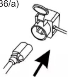
2-(36/b)
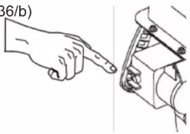
6.8 3ynnHa DnryHa (37, 38)
NONEPEDJXEHH!He6e3nekaYepe3 o6eptoBi eIemEnT npncTpo!BBeJeHH KINZIBOK B 3OHy PO3MiueHH O6epTOBx eIemEnTiB npNCtpoMOKe Ipn3BecTu Do cepNo3Hx TpaBM!
Hikon He li3bTe B o6eptOBn 1NeKOBn KOHBeep!
- NepemictiB (37/a) BaKinb rasy (37/1) y noIooxehnra «NobInbHO» (YepeNaxa).
- Ⅱo6 3anobirn 3amep3aHHIO, daTe WnekoBomy KOHBeepy Ta KpInbUaTci nonpaucOBaTu DOTN, DOKN BOHN He 6yDyTB MaKcImaJIbHO BInbHI BiD chiry. B IHwOmy BnnaIky KlnHObi peMeHi MoKyTB 6yTu NOnkOJKeHi NiJ Yac 3a-Nycky.
- BntTgHITb (38/a) KIIOU XINBHeHHa DBNrHyHa (38/1).
4.ДВИГУН ВИМИКаETбя. - BcTaHOBiTb (38/b) naJIuBnI KpaH (38/2) y noJoxKeHHr OFF (3aKp.).
7 EKCJIYATAUIA
7.1 NocatoK po60tn (39 - 41)
NONEPEJXEHH! He6e3neka uepe3 o6eptoBi eIemEnTu npucTpo! BBeJeHH KINUBOK B 3OHy po3MiueHnro o6epTOBx eIemEnTiB npucTpoIO MOKe PpN3BecTu Do cepNo3Hnx TpaBM!
HikoJI He JI3bTe B o6eptOBu IHeKOBu KOHBeep!
NONEPEIXEHH! He6e3neka BUKndaHnCTOPOHIX npeMetIb! He6e3neka OTpMaHnTpaBM Ta MaTepiabHnx 3bNTkIB Yepe3 BUNDaHHCTOPOHIX npeMetIb!
Hikon He cnpmaOByTe KaHaJI BnKndaHHa CHIry Ha IIOdeN, TBapIN, ABTOMO6iI, BkHa 4I DBepi.
- Bveiditb npncptpiB ekcnnyataciio.
- Ipepebipte noIoxeHHa KOIO6a BnKndaHn CHiRy Ta BiDpeYIIOHe HAnpMOK BnKndaHHa 3a DonomoroO pyKn (39/1).
- HanaIyIte BnCOTy BnKUdAHN (39/2).
- 3aBéπiTb DnBγH (DnB. po3di 6.7 "3anyck deuayHa (31-36), cmopjHKa 358).
- YbIMKHiTb nepeaCy dJa KOJIiCHoro npNbOda (40/3):
1-6 nepepaqi nepeHboro xOy, de 1 —HaINOBiBHiIa, a 6 —HaIWBnDla nepedaqa.
R1 i R2 — nepeəaqi 3aHbOro xOdy, De R1 — nobiIbHa, a R2 — wBnIsha nepe-daHa.
- Hatachitb (40/a) Baikinb 3yennenHn (40/4) IJIaIa3yHOBOrO npuBoda.
- Hatncitb (41/a) Baxinb 3uenneHHa (41/5) Jnra Kojichoro npnboda.
7.2 PpnnnHeHH po60tn (42)
- BiDnycTiB (Bi'EDHaIe) (42/a) Baxeni 3ye- nIeHHra (42/1) Inna3yHOBOrTa KOniChoro npuBoDiB.
3a06 3anobirn 3aMepe3aHHIO, daTe WHeKOBOMy KOHBeep Ta KpNlBHaTci NoppaioBaTH DoTN, DOKN BOHN He 6dyTb MaKcImaIbHO BInbHi BiD CHIRy. 3Mep3nn WHeKOBNI KOHBeep NOWKOJxye KINHOBI peMeHI.
Φpe3epHn CHIROOuNCHNK 3aIIuHaETbCg Ha Micci, UHeKOBn KOHBeep i KpNJbUaTka 3yINHIAOTbcR.
7.3 3mHa nepeaui IJI KOnicHOro npNbOda (41-43)
YBAG! He6e3neka noWkoJxHn npncIpo- H. Kopobka nepeauch 6ynde noWkoJxHa, kUo 3uePHeHHn He 6yde BmKHyTo nepei nepemKaHHaM nepeauch.
Cnooyu BmKHiTb 3yennneHHa, a nOtim nepeMkaTe nepedaY.
1. BiDnyctiB baxinb 3uenneHnK konichoro npuBoDa (42/1),TO6To BmKHiTb (42/a).
Ppumimka: UHeKoBu KoHeeep 3a6nOky-Embca, RaUo Uo2o 3ynuHmu, a nomim 3HO8y 3anycmmu Ha MOKpOMy ma cunbHomy chiay. 3abOpOHemcbcBidnyckamu baxinb3quenneHH nn3a3yHo602 npuboda!
- 3mHITb nepeauy 3a donomoroBaxkeJBA6Opy nepea (43/1).
- Hatachitb (41/a) Baixilb 3uenenneHHa (41/5) JIy KOJIICHO npBOda.
7.4 YcyHeHHa3akynopOBaHHaXoNo6a BnKnDaHHaChiY (42, 44)
8 NPMITKA 606 yHnKHyTn 3aKynOpIOBaHHB pa3i HaeBHocTi BaxkOro Ta MOKporo Chiry, noMOxNIBOcTI He nepepNaTe po6Oy UHeKOBOrOKOHBeepa.
KuO Chir 6JIbWe He BUNdaeTbcra HaneXHUM YINOM, PnunHOU cboMy MoKe 6yTu BiKnpaedH NcIry Ta IbOdy Ha UHeKOBOmy KOHBeepi Ta B KaHani BUNndaHH.
- BiDnyctitb (Bi'edHaIte) (42/a) Baxeni 3ye- nIeHHra (42/1) Inna3yHOBoro Ta KOnichoro npuBODiB.
- 3aŋnyuɪtB dBɪrŋH (ɪnB. pɔːdɪn 6.8 "3yɪnuɪkɑ deuəyHa (37, 38) ", cmɒpɪnka 358).
- BnKOpncToBnyTe iHcTpymEn Tn yuHenn (44/1), 06 o6epexHo BnDaJIHTn Chr 3 KaHaJy BnKnDaHH Ta IHeKOBOrO KOHBeepa.
KuO BnKaHaHH Chiry BCE ue HeDocTaTHc, 3BepHtbcrdo CneuaJIIOBaHOI MaICTePHi.
8 PEMOHT
NONEPEJXEHH! He6e3neka TpaBMyBaHH naC peMOHTHX po6it. HeaJIexHnpeMOHT MOKe npINBeCTn DO cepNo3Hx TpaBM iInpuyHeb HopMaJIbHOi po60tN.
IpoBedeHnpeMOHTnX po6it Do3BOJrEtbcraTilbKn cepBicHm ceHTpam BpuObHnka a-6o ynoBHOBaKeHm CneuaJIi3OBaHm KOMnaHiaM!
YnactynnHex BnnaKax npncTpii noTppe6ye TInbKn KbaJIqikOBaHOI nepeBipkn:
nicra Haizdy Ha nepekoody;
nicra panToboi 3yunHKn DnBuryHa;
nCnI NOUKOJKeHHa HHeKOBOrO KOHBeεpa NKnPJIbCuATKN.
9 TEXHlUHE OBCJlyROBvBAHHr TA DOrIaD
OBEPEXKHO! He6e3neKa TpaBMyBaHHa.
Pyxomi Detani Ta Detani 3 roctpIMN KpaMIMOxyTb npn3BecTN Do TpaBM.
3aBxHn Hocitb 3axnchi pykabuizi nd yac TexHicHoro i cepbicHoro o6cnyroByBaHHra TaOunueHHa!
BumkhItb DnHyH i nepekoHaItecB, 0o BIn 3ynnHBCra!
BHTaRHiTb HakoHeuHc CBiUKN 3anaJIIOBaHHa!
OunuTe npncptpi nicra Koxhoro BnKopnctaHna.3okpema, Bndanitb 3aInuK coJI.
He 06bpn3kyuTe npncptiB BOIOU. NpTaPnIaHHBaOIN BcepeHHy MoKe npN3BeCTn DoNoJOMKn (CNCTeMn 3aPaJIIOBaHHa, KAp6IopaTopa).
3aBxJn 3amHIOTe NOsKoJXeHI IyuHnKn.
IotpmyTeCg rpaiky texHioo6cnyroByBaHHa.
IOTpIMyTecb KepiBnTuBa NO DnHyH.
9.1 FrpaΦik TexHicHoro 06cnyroByBaHHa
IpeepKoXHM BnKOpncTaHHaM
IpeBipraIe pIBeHb MaCTnla (INB. KepiBHNuTBO NO DBNyHy).
IpepebipnyTe 3pi3hi 6oJtn.
IpepeBipraTe npncTpiHa HaraBHicTh noUKoDxKeHb.
IpeBipraTe BiCyTHiCt b 3aMeP3nOro uHeKOBOrO KOHBeepa.
Yepe3 nepsi 5 rodn np6oTn
3amHIOTe MoTOpHe MaCTnIO (INB.KePiBHNU TBO NO DBNyHy).
KoXHi 8 roHn po6Otn
3MaUyTe UHeKOBn KOHBeep.
KoXHi 3 Micaui
IpeBipraTe Tnck y uHax.
3mauyeKeIbueXoJIO6aBnKaDaHHa CHiY 3a DonOMOrOIO MaCTnIbHnCi.
Ulopoky
3amHIOIe CBiKn 3anaIOBaHHa (INB.KePiHNuTBO NO DBNrHy).
3MaUyTe UHeKOBn KOHBeep.
3amHITb MOTOpHe MaCTnJO.
9.2 3MaueHHra WHeKOBoro KOHBeεpa (45)
3a donomoroio nicToeta dna 3MaueHHBdaBiTb (npn6n3HO 2-3 HataNcKaHH) yHibepcaJIbHe MaCTnIO do MaCTnIbHnci (45/1).
9.3 Texo6cnyroBvBaHHKoJichHOrTa nla3yHOBOr npNbOdB (08)
I NOPEJXEHH! He6e3neka TpaBMyBaHH nId Yac Texo6cnyroByBaHH. HenpaBnIbHe Texo6cnyroByBaHH MOKe npNBecTn Do cepNo3Hx TpaBM i nopuyueH HopMaIbHOi po60TN.
PeryIIOHe 6oyDeHicbKn Tpoc, TiIbKn kK- IIO DBNyH BUMKHeHn.
3aIywiTb DBNrHy, RaIO He BdaeTbcB BMKHyTN KOJICHN i INa3yHOBn npNBOuN.
He HamaraTeCBAIpemOHTyBaTn, HeraHo 3BepHITbcra do ABTopu3ObaHO MaicTePHI.
H NPMITKA HaBhictb BOJOrn Ha 6oydeHcBkOMy Tpoci MoKe npu3BeCTn Do Kopo3i a6o 3a-Mep3aHHa. PoUKoJxehN 6oyDeHcBkN Tpoc Notpe6ye 3amHn.
BidperyIIOte 6oyHeHcBkN Tpoc
Kuio niacpobotnDburyha 6ilbwe He Bda-ctbcyaBIMkHTN KOIICHN a6o nla3yHOBN npBOHn,TO Tpe6a BiDperyIIOBATN BiIDNOIBHN 6oydeHicckn TPOC.
- Ocna6Te KOHTprayky (08/2).
- Поветаши ренильни часни boуденibckoro trpoca (08/1) у habрamyстпkn (08/a), дки boуденibckn trpoc 6iNbwe He npobucatime (лгke haTajxHH).Пд чac noBeptaHHТрmaite trpoc,шб bH He nepeKpyyBaBCra.
- Kontrprainy (08/2) Tpe6a 3ataryn (08/b).
- Κόb πepeBipuTn HanaWtYBaHHa, 3aBeiTb dBvryH yBIMKHiTb KOJIcHm i Pna3yHOBn npuBOAn.
5.Якwo konichni i nla3yHOBn npnbOAn BCE OJHO He Bdaetbcra 6e3neuHO 3'edHaTn Ta BiD'edHaTn, pncptpi CJIid DOCTaBNTn Do aB-Topn3OBAHOI MaNCTepHI.
9.4 3aHa 3pi3Hnx 6oJtIb (30,46)
Дя 6e3neKn onepaTopa Ta npucTpOu 3piHi 6oTn (30/1) moKytb po3ipBaTncn icJЯ 6NokyBaHHa SHeKOBOro KOHBeepa.
I NPMITKA NoUKoJKeHHi 3pi3Hi 60NTu Tpe-6a 3amHHTn Ha opurHaJIbHi. JKUO BHKOpNCToBvIOTbcr He3aTBePdKeHi 3anuaCTHn, npNCTpiM OKe 6yTN CINbHO noUKoJKeHo!
- BumkhItb npncptpi i BNTaHrHiTb hakoHeuHK CBiK3anaJIIOBaHHJ.
2.3HIMITb (46/a) npyHHnΦikCaTOp (46/1). - BnMiTb (46/b) noWkoJxKeHi 3pi3Hi 6oJItn (46/2).
- IpepeBipTe BaI Ha HaaBHiCTb NookoJKeHb.
- YctaHOBiTb HOBI 3pi3Hi 6oJTNi 3a6NokyTe ix npyKHHM fikCaTOPOM.
10 YCYHEHHA HECNPABHOCTEi
OBEPEXHO! He6e3neka TpaBmyBaHHa. Puyxomi Detani Ta Detani 3 roctpIMKpaMm M Kytb npn3BcTn Do TpaBM.
3abxHn Hocitb 3axnchi pykabuCiPi qacTexHicHoro i cepBichoro o6cnyroByBaHHra Ta OunueHHa!
BumkhItb DnHyH i nepekoHaITecb, 0o BIn 3ynHHBCa!
BHTaHrHiTb HakoHeuHnK CBiUKN 3anaIIOBaHH!
8 NPMITKA y pa3i BnHnKHeHH nOuKO-dKeHb, kI He 3a3HaueHi B cIi Ta6IuCi, a6o no-koJxKeHb, 3 KIMN KOpNCtYBaH He MOxE BnopaTncsCa, cIiD 3BepHyTncsDo HaIoCnJyK6n niTpMkn.
www.al-ko.com/service-contacts
14「APAHTI
До 3akihueHЯ CTpOKy DabHocTi peKnaMaui, yCTaHOBNeHoro 3a 3akoHOM, Bnpo6Hk yCyBaE MOxNBI DeΦeKTH MATEPIAny YN Bnpo6HnHm 6paK 7Jnxom pEmoHTy a6O 3amHn (Ha cBiY Bu6ip). CToPOK daBHOCTI Bu3HaayetbCra 3aKOHOdaBCTBOM KpaIHn, y kIi npInaD 6byNo KynneHo.
Tapaantia 36epiraetbce nIwe 3a TaKnx yMOB:
IOTpmyTeCzboro noci6Hnka 3 ekcnnyatauii
BnKOpncTaHH npuJa 3a npn3HaeHHaM
BnKOpncTaHHOpriHaJIbHnx3anYactNH
TapaHTia anHyIOeTbCra 3a TaKnx yMOB:
CamaobinbHn peMOHT
CamaBilbHa 3MiHa TexHiuHx XapaKTePunctIK
BnKOpncTaHH He 3a npu3HaueHHaM
TapaHrHe NouHpOeTbCHa:
I NowkoJxehnnaKoap6oBOrO nokpTTT, cnpuHHe 3BuayHm 3HOuyBaHHaM
YacTINH, 3HOwIOTbCn, No3HaueHi y BiIDOMocTi 3anachnx YacTINH paMKoIO;XXXXXX (X)
BbHyHn BHytpiunhbo 3ropaHHa (ie rapaHTia Bnpo6nka DbHyHa)
Bidnik rapaHTiHoro TepmiHy po3nouHaetbcra 3 daTn npud6aHHBnpo6y nepuHM KINcEum CNOXbAueM. Data npud6aHH Bkazha H ByeKy. Y pa3i BnHKHeHHra paaHTiHORo BnnaDky 3BepHiTbcra 3 cieUO 3aBOTo Ta opurHAMOM KBNTaHci, 10 NiTBePdxKy e NOKynky, Do CBOrO dIlepa a6o B haN6nnxuy ABTOp3OBaHy cepbichy cnxy6y. Lc rapaHTiHHe 3obov'3aHH He 3MiHoc BCTaHOBneHi 3aKOHom PpeTeH3iI NOKyn4 do npodabzra.
Russia
HmnpTeB Pocncko Feepaun
OOO «Ал-КО КOBEP», 107553, r.MockBa, у.Болшая Уерknizobcka, d.24a,ст.76, тел.8-800-550-1931, info@al-ko.msk.ru
Ukraine
TOB AJI-KO KOSEP
ByI. BpObaPcbKa 156,07442
c. Beiika Dimepeka, BpOBaPcbKi paH,
KniBcbKa 06NaCTb, YkpaHa
Telefoh/phiKc: +38 044 392-07-08 / 09
UK
Imported by: AL-KO Gardentech UK Ltd, Murray way, Wincanton, Somerset, BA9 9RS / UK | +44 (0) 1963 828055
shop.uk@al-ko.com | www.alko-garden.uk
AL-KO Service: www.al-ko.com/service-contacts

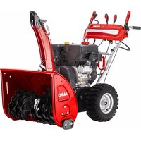
- ABOUT THESE OPERATING INSTRUCTIONS
- Symbols on the title page
- Symbol Meaning
- Legends and signal words
- PRODUCT DESCRIPTION
- Designated use
- Possible foreseeable misuse
- Safety and protective devices
- Clutch lever
- Adjustable snow discharge spout
- Scope of supply for 620 E III
- No. Component
- Symbols on the appliance
- Safety signs
- Operating signs
- Product overview - 620 E III (01)
- SAFETY INSTRUCTIONS
- WARNING! Danger of explosion and fire.
- Safety instructions in accordance with ISO 8437, Annex A
- Getting to know the appliance
- Preparation
- Operation
- Maintenance and storage
- WARNING! Serious hand injuries when cleaning the blocked discharge channel!
- Safety instructions relating to operation
- Handling of petrol and oil
- UNPACKING APPLIANCE (02)
- ASSEMBLY
- Necessary tools
- Fitting the lower brace (03, 04)
- Fitting the operating panel (05)
- Installing and adjusting Bowden cables for travel and worm drives (06 - 11)
- Adjusting the Bowden cable (12)
- Checking the Bowden cable setting (13)
- Mounting the rod for the gear selector lever (14, 15)
- Fitting the levers for gear selection and discharge height (16)
- Plugging in the heater and lighting plug (17)
- Fitting the snow discharge spout (18-21)
- Connecting the Bowden cable to the discharge flap (22)
- Fitting the snow discharge spout hand crank (23)
- Attaching the Bowden cable (24)
- START-UP
- Operating material
- NOTE Observe the enclosed operating instructions for the engine!
- Filling with engine oil (25)
- Filling with petrol (25)
- Checking the tyre pressure (26)
- Adjusting the clearing height (27 - 29)
- Skids worn (29)
- Checking the shear pins on the appliance (30, 46)
- Starting the engine (31-36)
- Starting process (31 - 34)
- Manual start (35)
- V starting process (36)
- Stopping the engine (37, 38)
- OPERATION
- Starting clearing (39 - 41)
- Stopping clearing (42)
- Changing gear for the travel drive (41 - 43)
- REPAIR
- WARNING! Risk of injury during repair
- MAINTENANCE AND CARE
- CAUTION! Risk of injury. Sharp-edged
- Maintenance schedule
- Before every use
- After the first 5 operating hours
- Every 8 operating hours
- Every 3 months
- Once a year
- Greasing the transport auger (45)
- Servicing the travel and auger drives (08)
- Adjust Bowden cable
- Replacing the shear pins (30, 46)
- HELP IN CASE OF MALFUNCTIONS
- STORAGE
- DISPOSAL
- AFTER-SALES/SERVICE
- GUARANTEE
- TRADUCTION DE LA NOTICE D'UTILISATION ORIGINALE
- Table des matieres
- GARANTIE
- GARANCIJA
- JAMSTVO
- OINC INPOIN3BOIDA
- HameHcKa ynoTpe6a
- Moryha npedBnDnBa norpesha ynoTpe6a
- Be36eHocn n 3aHTNTHmexaHN3Mn
- A yI03OPEHbE! OnaChocT oD noBpeJe.
- Ponyra KBaunla
- IOnecnB n36aunBaChera
- O6m nCnopyke 620 E III
- Cm60n 3Nauehe
- PperneI npOn3bOda 620 E III (01)
- Бр.Сатави дeo
- 3BE3BEdHOCHE HANOMEHE
- Be36eHocHe HAnOmeHe npema ISO 8437 npnior A
- PpeTxoJHo 3HaHe
- Pnpnpema
- PykoBaBe
- OdpkaBaHbe ncknaHnWTeHe
- Cnryphoche HanomeHe 3a oncnyKuBaHbe
- 3.3PykoBaHbEm6eH3nHOMyJbeM
- OTNAKBAHbE YPeBaJA (02)
- MOHTAXA
- YI03OPEHbE!OnacNoCT 36or
- POnTe6Hn aHaTn
- Bp.Anat
- MoNTaxa doIbe wunke (03, 04)
- MoHTaxa KOHTpOJnHOr naHeJa (05)
- MoNTaxa n noDeuBaHbe BnydeHOBux Ka6NoBa 3a BO3Hn InyxHn NorOH (06 - 11)
- Φино подашаразе Боуденовor kaбna (12)
- PpOBepa nopeaBaHaBoydeHOBor ka6na (13)
- MoNTaKa 3a pyuNc y 3a n36Op 6p3nHe (14, 15)
- Kn3aun cy nctpoeHn (29)
- Побера вижаа 3a 3awTHTy od npeontepeheha ha ypehajy (30, 46)
- PAXbA! OnachocT od ouTeheBa
- NokpeTaHe MoTopa (31-36)
- ONACHOCT! OnachocT no XHBOT 360r
- PAXHbA! OnachocT od owteheBa
- Noctynak nokpeTaHa (31-34)
- PyuHNo nokpeTaHe (35)
- NocTynak noKpeTaHa Ha 230 B (36)
- 3ayctabbahe MoTopa (37, 38)
- PYKOBAHbE
- POKpTaIbe YnshHeBa (39 - 41)
- 3ayctaBbahe uuheha (42)
- 7.3ПометабрзинезаВОЗнnoroh(41- 43)
- YknaBaBe 3aenIbeBa y n36aunBaCy chera (42, 44)
- NONPABKA
- ODPKABAHBE HEGA
- 9.1ПланОдржаваьа
- Ppe cBaKe ynoTepe6e
- HaKoH npBnx 5 paDnX yacoba
- CbaKnx 8 paHnx yacOba
- Cbaka Tpn Meceua
- Todnhe
- NpMa3nBaHe cnpaJe 3a cHer (45)
- OdpkaBaBe BO3HOr n nyxHor noroHa (08)
- POnecnteBoydeHOBO yke
- 3aMeHa Bnjke 3a 3aWtNTy oD npeonTepeheBa (30, 46)
- NOMOT Y CJNYAJY CMETHBn
- Pe3epBn DneIOBn
- 11CKJIaIINuTEHBe
- OJNAHbE
- CJNYKBA 3A KOPNCHNIKE/CEPBNC
- TAPAHUNJA
- ZÁRUKA
- BEZPEČNOSTNÉ POKNY
- A GÉP KICSOMAGOLÁSA (02)
- GARANTI
- Stille inn romhoyde (27 - 29)
- VEDLIKEHOLD OG PLEIE
- GARANTII
- GARANTIJA
- GARANTIA
- CnmboHn HaHaayaHaTa cTpaHua
- CnmboJ 3HaueHne
- Pa3aCheHna Ha yCIOBHNTe 06o3HaueHnN n CnHnHTe dymn
- OПИСАНЕ HA ПОДУКТА
- N3noJ3BaHe no npedHa3NaueHne
- Bb3MOxHa npeBnDnMa HnpaBnJHa ynoTpe6a
- 3aunTHn npeDna3Hn yctpOuCTBa
- CbeHHTeJenHOCT
- PerynpyeMo n3XBbPpIHe Ha cHera
- OkomnneKToBka Ha DocTaBkata Ha npoDykTa 620 E III
- 3Haun 3a 06cnyXBaHe
- Cnmbon 3haueHne
- IperIeHa npOdykTa 620 E III (01)
- No KomtoHeHT
- No KomnoHeHT
- YKA3AHNIA 3A BE3ONACHOCT
- Yka3aHn 3a 6e3oNaCHOCT CbIaCHO ISO 8437 PpInJoxKeHne A
- PpeBapnteHa noDrotobKa
- IoprotoBka
- UnpaBneHne
- Pndpbkka ncbxpanHeHne
- Yka3aHnna 3a 6e3oNaChocT npn o6cnykBaHe
- Pa6oTa c 6eH3nH macJo
- PA3OPIAKOBAHE HA MALUNHATA (02)
- MOHTAX
- Heo6xOaIMn HhCTpyMeHTN
- MoHTuPaHe Ha DoHaTa dpbXka (03, 04)
- MoNTnpaHe Ha nHaEna 3a ynpaBneHne (05)
- MoNTaK HacTpoiKa Ha XnIaTa 3a 3aBnXBaHeTo Ha XoObAta Yact N Ha ShHeKa (06 - 11)
- DonbHnTeHNO peryInpaHe Ha XnNoTo (12)
- Поберка на HabстpoиkaТа на КИЛOTO (13)
- MoNTiPaHe Ha rpeDa Ha IocTa 3a n36Op Ha ckopoCt (14, 15)
- MoHTnpaHe Ha loCTa 3a n36Op Ha CKOPoCT H BnCOUHa Ha n3XBbPJIHe (16)
- 3akpenBaHe Ha uencena 3a oToPJIeHne n OCBetJeHne (17)
- MoNTIpaHe Ha yCTpOncTBOTo 3a n3XBbPJIHe Ha cHr (18 - 21)
- 3aKpenBaHe Ha XnIo KbM n3XBbPpIaTa KnaIa (22)
- MoNTIpaHe Ha MaHbEJIaTa 3a yCTPOcTBOTO 3a N3XBbPJIHe Ha CHr (23)
- 3aKaayane Ha XnNoTo (24)
- NYCKAHE B EKCPIIPOATAU
- Pa6oTHn cpeDCTBa
- HanBaHe Ha DnRaTeJHo MacNo (25)
- Hanibahe Ha 6eH3nH (25)
- NpOBepka Ha HAnraHeTo B rymnte (26)
- CnnpaHe Ha peXmHa 3a noUcTbaHe Ha cHr (42)
- 7.3ПпeвклунчынHa ckopoct 3a npnDbvnxBaHe (41-43)
- OTeTpaHЯBaHe Ha 3aApbCTBaHnB yCTpoIcTBOTo 3a N3XBbPnA He Ha CHERa (42, 44)
- PEMOHT
- I PEPDyPPEKDEHNE! OnachocT OT hapaHЯBaHnno BpeMe Ha peMOHTHa DeHOCt.
- NOДРьЖKA И NOЧNTBAHE
- BHIMAHHE! Onachoct OT hapaHЯBaHe.
- RaΦnK 3a noDpBxKa
- PpeBvBaKyaynotpe6a
- Cnei npBnTe 5 pa6oTHn Yaca
- Ha BceKn 8 eKcnnoaTaunOHn Yaca
- Ha Tprn Meccea
- Toaunho
- Cma3BaHe Ha TpaHcNOpTHnA WHeK (45)
- PdPbXka Ha 3aBnXBaHeTo Ha KOJIeNoTo n UHeKa (08)
- PerynpaHc HxNIOTo
- CmHa Ha cpr3Baun 6oJTObe (30, 46)
- NOMOUI PNI HEN3INPABHOCTN
- OINCAHNE IPOdYkTA
- IcnoJb3ObaHne no Ha3HaueHnIO
- Cnyan npeducmoTpeHHoro npImeHnna
- PpeoXpaHntbHbIe n 3aunTHbIe yctpoiCTBa
- Pbivar cuenneHn
- Perynpyembmyeio6 Bbyrpy3Kn Chera
- CmboJIbI 3KcIIpyaTauN
- O63op n3denn 620 E III (01)
- Heo6xOaIMbIe INHCTpyMeHTbI
- Ho- uHcTpymeHTa Mep
- MoNTaX HIXKHeRo 3JIeMeHTo pyKOaTKn (03, 04)
- MoHTax naHEn ynpaBHeHHa (05)
- MoNTaX upeYlnpObaHne TopMo3HbIX TpocOB IJI KONECHORO u CepBraHORO npIBoDa (06-11)
- PerylnpoBaHne TopMo3Horo Tpoca (12)
- Поберka Habстpoи Topmo3Horo Tpoca (13)
- MoNTaX TAYn pbIyara nepeKJIoueHn nepeDaU (14, 15)
- MoNTaX pbIyara Bbl6opa nepepaN BBICOTbI Bblrpy3Kn (16)
- NpokJIIOUeHne uTeKepa cnCTeMbI OToONJIeHnN IOdCBETKn (17)
- MoNTaX XeIIO6a BbIrpy3KN cHera (18 - 21)
- PnncoeDHeHne TOpMo3HOro TpOca K pa3rpy3OuHomy KnaNaHy (22)
- Kakdbie 8 yacob pa6oTbI
- Kakdbie 3 Mecya
- pa3B roD
- Cma3bBAHHe IHEKOBORo TpaHCnOpTepa (45)
- KonechbI n cepBryhbl npBOD (08)
- OTperpylnpoBaTb TopMo3HOn Tpoc
- 3aMeHa cpe3HbIX uTnΦTOB (30, 46)
- YCTPAHEHNE HENCPABHOCTEIN
- TAPAHTNIA
- IPEKJIAD OPINIHJY NOCIBHnKA 3 EKCIIyATAUII
- 3mict
- IHΦOPMAUJII IPO NOCIBHNIK I3 EKCPIYATAUII
- CnmboHa THTyIbHi cTOpIHci
- CmB0J3HaueHHa
- YMOBHnNo3HaueHH Ta CnHnBHi CIOBA
- OINC INPNCPOHO
- BnKOpncTahHra np3HaueHHaM
- MoxJIbIe nepe6aueHe BnKOpncTaHHa
- 3anobixhi Ta 3axnchi eIeMeHTn
- Baxijb 3yenJenneHH
- Kono6 BnKnDaHHa Chiry, 00 perynoeTbcra
- yMOBHI no3HaueHHa npncTpoko
- Mitkn 6e3nekn
- 2.6OrnBnpo6y 620 E III (01)
- Heo6xIDHn iNCTpyMeHT
- HoMep
- IhCTpyMeHT
- MoHTaX HxHbOi nonepeuHH (03, 04)
- MoHTaK nAHeI KepyBaHHa (05)
- MoHTaX Ta peRyIIOBaNHn 6oydHiBCbKx TpOcIB dJa KJIichoro Ta nJa3yHOBOro npNBoID (06-11)
- Toyne perynobHHa 6oydeHicbkoTpoca (12)
- IpepeBipka peyIIOBaHnHa 6oydHiBCbKOro Tpoca (13)
- MoNTaX TAYn BaxKeIy Bv6Opy nepeDaayi (14, 15)
- MoNTaX BaXeJI Bn6Opy nepeaui Ta BnCOTn BnKnDaHHra (16)
- 5.8Плкюechншт ekepacnctemOnaJIeHH Ta nCbitKn (17)
- MoHTaX XOJIo6a BnKnDaHHa CHIry (18 - 21)
- KpinJIeHnHa 6OyIeHbCbKOro TpOca Ha KpnUzI XOJIo6a BkNJaHHa (22)
- MoHTax pyKn dJa peryIIOBaHHa JKOJ06a BKNDaHHa CHiry (23)
- HabiyyBaHHa 6oydeHicbckoTpoca (24)
- BBEDEHHB EKCPIIyATAUIO
- 6.1Палнвно-Mactильни MaTepiaJIH
- 3aHbHaHH MoTOpHoI OINBn (25)
- 3aHbHaHH6eH3nHy (25)
- IpeBipka TnCKy B uHax (26)
- PerynobHH Bucotn po6otn (27 - 29)
- OBEPEXHO! He6e3neka TpaBmyBaHHa.
- No03Kn 3HoWeHi (29)
- IpebeBipka 3pi3Hnx 6oJTIb Ha npncTpoi (30,46)
- YBAGA! He6e3neka nowkodxeHHa 06-
- 3anyck DBruryha (31-36)
- Ppoec 3aBeDeHHa (31-34)
- 3anyck BpyHy (35)
- PpOec 3anycky 230 B (36)
- 3ynnHa DnryHa (37, 38)
- EKCJIYATAUIA
- NocatoK po60tn (39 - 41)
- PpnnnHeHH po60tn (42)
- 3mHa nepeaui IJI KOnicHOro npNbOda (41-43)
- YcyHeHHa3akynopOBaHHaXoNo6a BnKnDaHHaChiY (42, 44)
- TEXHlUHE OBCJlyROBvBAHHr TA DOrIaD
- OBEPEXKHO! He6e3neKa TpaBMyBaHHa.
- FrpaΦik TexHicHoro 06cnyroByBaHHa
- IpeepKoXHM BnKOpncTaHHaM
- Yepe3 nepsi 5 rodn np6oTn
- KoXHi 8 roHn po6Otn
- KoXHi 3 Micaui
- Ulopoky
- 3MaueHHra WHeKOBoro KOHBeεpa (45)
- Texo6cnyroBvBaHHKoJichHOrTa nla3yHOBOr npNbOdB (08)
- BidperyIIOte 6oyHeHcBkN Tpoc
- 3aHa 3pi3Hnx 6oJtIb (30,46)
- YCYHEHHA HECNPABHOCTEi
- 14「APAHTI
- Russia
- Ukraine
- UK
Brand : AL-KO
Model : SnowLine 620E III
Category : Snow blower