
SnowLine 620 II - Snow blower AL-KO - Free user manual and instructions
Find the device manual for free SnowLine 620 II AL-KO in PDF.


| Product Type | Snow Thrower |
| Brand | AL-KO |
| Model | SnowLine 620 II |
| Engine | Thermal, 4-stroke, single-cylinder |
| Displacement | 208 cc |
| Power | 5.5 kW (7.5 hp) |
| Fuel | Unleaded gasoline |
| Fuel tank capacity | 1.5 L |
| Working width | 56 cm |
| Suction height | 35 cm |
| Wheel diameter | 13 cm |
| Weight | 45 kg |
| Dimensions (L × W × H) | 100 × 60 × 60 cm |
| Starting system | Electric (12 V battery) and recoil manual |
| Speeds | 5 forward / 2 reverse |
| LED headlight | Yes |
| Discharge | Remote adjustable (180° rotation) |
| Noise level | 96 dB(A) |
| Warranty | 2 years (parts and labor) |
| Spare parts | Available (belts, blades, spark plugs, filters) |
| Repairability | Repairability index 7.5/10 |
| Routine maintenance | Engine oil change, spark plug and air filter replacement |
| Safety | Emergency stop, safety lever, hand guards |
Frequently Asked Questions - SnowLine 620 II AL-KO
User questions about SnowLine 620 II AL-KO
0 question about this device. Answer the ones you know or ask your own.
Ask a new question about this device
Download the instructions for your Snow blower in PDF format for free! Find your manual SnowLine 620 II - AL-KO and take your electronic device back in hand. On this page are published all the documents necessary for the use of your device. SnowLine 620 II by AL-KO.
USER MANUAL SnowLine 620 II AL-KO
natural_image
Technical illustration of a snowman lawn tool with visible blades and motors (no text or symbols)| D | DK |
| GB | S |
| F | N |
| I | FIN |
| SLO | EST |
| HR | LV |
| SRB | LT |
| PL | RUS |
| CZ | UA |
| SK | BG |
| H | RO |
INFORMATION | MANUALS | SERVICE
AL-KO SCHNEEFRÄSE
Snow Line 560 II, 620 II, 620E II
Betriebsanleitung


469186_c I 05/2012

GB: Operating instructions....22
natural_image
Mechanical assembly diagram showing a cylindrical component with attached parts and numbered callouts (1), no readable text or symbols present.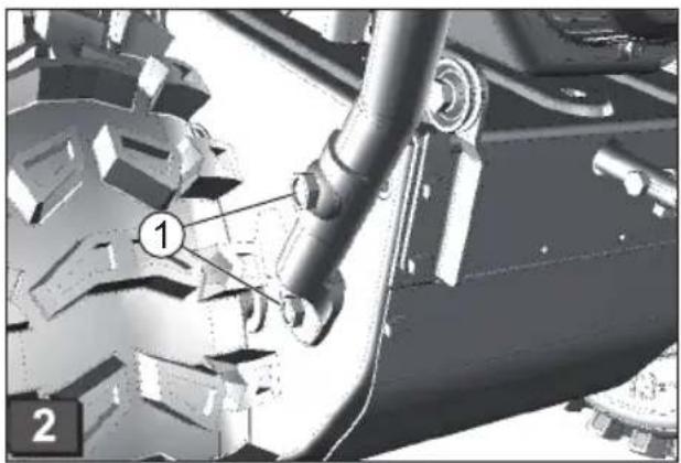
natural_image
Mechanical assembly diagram showing gear and pipe components (no text or symbols)
natural_image
Front view of a tracked vehicle chassis with two labeled components (1 and 2), showing exposed tires and structural beams (no text or symbols beyond labels)

natural_image
Mechanical lever mechanism diagram showing two configurations with curved arrows indicating motion (no text or symbols)
natural_image
Mechanical lever mechanism with handle and lever assembly (no text or symbols visible)
O

natural_image
3D mechanical assembly diagram showing pipe connections and a directional arrow (no text or symbols)

natural_image
Illustration of a hand pouring liquid into a container with a downward arrow indicating flow (no text or symbols)

natural_image
Diagram of a medical or laboratory device with an arrow indicating motion, showing a shaft and connector (no text or symbols)

natural_image
Diagram of a mechanical device with a helical spring and two pins, showing directional arrows (no text or symbols)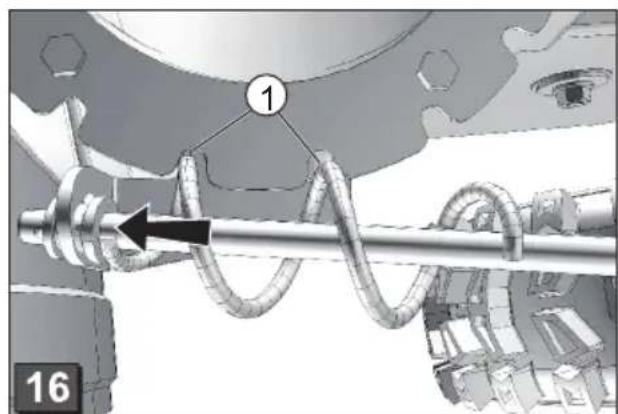
natural_image
Mechanical assembly diagram showing a shaft and gear mechanism with labeled component 1 (no text or symbols beyond labels)O
natural_image
Mechanical assembly diagram showing a rotating component with labeled parts (1 and 17), no readable text or symbols beyond labels.
natural_image
Mechanical assembly diagram showing a rotating component with pipe and housing (no text or symbols)
natural_image
Mechanical device with lever and handle, showing motion arrow (no text or symbols)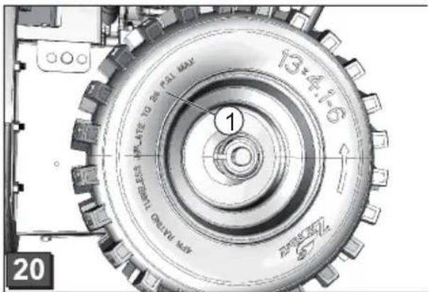

natural_image
Close-up of a mechanical component with labeled parts and rotation arrow (no text or symbols beyond labels)

natural_image
Mechanical assembly diagram showing a rotating component with arrows indicating motion (no text or symbols)O

natural_image
Mechanical assembly diagram showing internal components and motion paths (no text or symbols)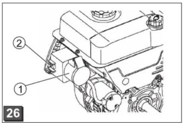



natural_image
Technical diagram of a mechanical assembly with no visible text or symbols
©


natural_image
Mechanical device with articulated arms and a numbered component (no visible text or symbols)

natural_image
3D mechanical assembly diagram showing interconnected gears and a central component, with no visible text or symbols

Zu diesem Handbuch
natural_image
Pure electrical connector diagrams without any text or symbols2.

natural_image
Line drawing of a hand pointing at a mechanical component (no text or symbols)Motor ausschalten
Antonio De Filippo, Managing Director
About this manual
Read this manual before assembly. This is a pre-requisite for safe and trouble-free operation. Before using this machine, make sure that you understand how to operate it and are familiar with the operating controls.
■ Please observe the safety and warning notices in this manual and on the machine.
This manual is a permanent part of the product described and should be handed over to the customer when the machine is sold.
Meaning of symbols

Caution!
Close adherence to these warning notices can prevent personal injury and/or property damage.

Special information for improved understanding and correct handling.

The camera symbol refers to illustrations.
Contents
About this manual 22
Description of product....22
Safety and protective devices....22
Delivery contents......24
SSafety instructions....24
Assembly 25
Adding fuel and engine oil 26
Getting ready for operation....27
Starting the engine 28
Operation....29
Maintenance and care 30
Storage 31
Repairs 31
Disposal....31
Troubleshooting....32
Warranty 33
EC declaration of conformity 33
Description of product
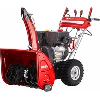
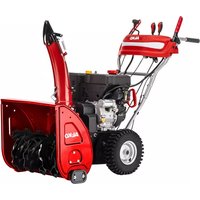
This manual describes the various AL-KO snow blower models. The models vary according to their snow clearance width and engine power, and whether they have an electric starter and headlight.
Identify your model using the product illustrations and descriptions and the identification plate.
Intended use
This machine is intended solely for private use in clearing snow around the home and from smaller parking areas.
Any other use is not in accordance with its intended use.
Incorrect use
This machine is not intended for use in public areas, parks, sporting arenas, or in agriculture and forestry.
■ This machine must not be used for commercial purposes.
Safety and protective devices

Danger - risk of injury!
Do not disable safety and protective devices!
Clutch lever
The machine has two clutch levers located on the guide handle. Release both clutch levers in case of danger.
■ Clutch lever for the snow discharge auger drive. Auger drive is stopped.
■ Wheel drive clutch lever. Wheel drive mechanism is stopped.
Adjustable snow discharge chute
Adjust the snow discharge chute so that the discharged snow does not cause injury to persons or animals and does not damage buildings, vehicles or other objects.
Make sure that traffic is not impaired and that drivers are not endangered.

Product overview (G)
| 1 Wheel drive clutch lever |
| 2 Guide handle |
| 3 Auger drive clutch lever |
| 4 Snow discharge chute with protective guard |
| 5 Engine |
| 6 Drive speed selection lever, 5 forward and 2 reverse speeds |
| 7 Hand crank for adjusting snow discharge chute |
| 8 Shield |
| 9 Auger |
| 10 Height-adjustable skid plates |
| 12 Headlight* |
| 13 Impeller |
| 14 Snow cleaning tool (attached to shield) |
| 15 Clearing plate |
| 16 Spark plug connector |
| * Snow Line 620E II only |
Symbols on the machine
| Caution!Special care required during use. | |
| Read the operating instructions before start-up. | |
| Keep away from snow discharge area. Danger from snow discharge. | |
| Keep hands out of snow discharge chute. | |
| Keep hands and feet away from auger. | |
| Switch off engine before working on the machine. | |
| Wear eye and hearing protection. | |
| Keep away from rotating parts to avoid the risk of getting entangled. | |
| Disconnect spark plug connector before performing maintenance and repair work. | |
| Keep others away from dangerous areas. |
Models
| Typ < -> M | ||
| 560 II 560 mm 182 cm3 | ||
| 620 II 620 mm 212 cm3 | ||
| 620E II same as 620 II, | ||
Delivery contents
■ 1 Snow blower
■ 1 Snow cleaning tool
■ 1 Operating and assembly manual
■ 1 Replacement parts list
■ 1 Spark plug wrench
■ 1 Engine manual
■ 1 Guide handle
■ 1 Snow discharge chute
■ 3 Parts for fastening snow discharge chute
■ 1 Hand crank for snow discharge adjustment
■ 1 Drive speed selection lever
■ 4 Replacement shear pins with safety split pins
■ 2 Engine key
■ 1 Headlight (620E II)
SSafety instructions

Caution!
Use the machine only in perfect working order.

Danger - risk of injury!
Do not disable safety and protective devices!

Danger - risk of injury!
Do not store the machine in areas in which petrol fumes could come in contact with open flame or sparks.
Keep the area around the engine, exhaust, battery case and fuel tank free from petrol and oil.
■ Make sure you can handle the machine safely and know how to stop operation.
- Keep others, especially children and pets, away from the operating area.
■ The machine operator or user is responsible for accidents involving other persons and their property.
■ Children and persons who are not familiar with operation are not permitted to use the snow blower.
- Observe the local regulations governing the minimum age of the operator.
■ Do not operate when under the influence of alcohol, drugs or medication.
■ Wear appropriate work clothing.
Winter clothing
Sturdy, non-slip footwear
■ Eye protection (safety glasses or visor)
■ Hearing protection
■ Work only when there is adequate daylight or artificial lighting. Adjust your speed to conditions. Walk, don't run.
- Keep hands, feet and clothing away from the auger and impeller.
- Observe local ordinances regarding operating times.
■ Never leave the machine unattended when it is ready for operation.
■ Be careful when working on slippery surfaces. Danger of slipping, especially when moving in reverse. Adjust your speed to conditions.
■ Operate machine only if completely assembled with functioning protective equipment.
■ Prior to each use, check the machine for damage and have damaged parts replaced before using.
■ Disengage the wheel drive and auger before starting the engine (both clutch levers upright).
In the following situations, switch off the engine and wait until the machine is at rest, then disconnect the spark plug connector:
- When not using the machine
During cleaning and maintenance
Before making adjustments
■ When malfunctions occur
Before loosening blockages
Before unclogging
■ After hitting obstacles
If malfunctions or unusual vibrations occur
- Check the area to be cleared completely and carefully. Remove door mats, sleighs, boards, cables and other objects.
■ Do not use the machine on steep slopes due to the risk of slipping or tipping. Exercise additional caution when turning on sloped surfaces.
■ Use the skid plates to adjust the distance of the clearing plate from the surface. Do not operate the machine on gravel surfaces.
■ Never lift or carry the machine while the engine is running.
■ Do not eat, drink or smoke while filling with petrol or engine oil.
■ Do not inhale petrol fumes.
Take precautions to ensure that discharged snow does not cause injury to persons or animals or damage to buildings, vehicles or other objects. Make sure that traffic is not impaired and that drivers are not endangered.
- Keep hands out of the snow discharge chute while the machine is running.
- Keep hands and feet away from the auger and impeller while the machine is running.
■ Do not clear snow from roofs.
Assembly

Caution!
Do not operate the machine until it has been fully assembled.
Required tools
■ 2 Open-end or ring spanners, size 10
■ Open-end or ring spanner, size 13
■ Hex key, 5 mm
■ Combination or needle nose pliers
Screwdriver
■ Spray oil
■ Tyre pump with pressure gauge (auto tyre valve)
Assembly sequence
Attaching and adjusting control cables

The same procedure applies for the wheel drive and auger control cables.
- Guide the control cable upward:
■ Guide the auger control cable through the
opening on the drive speed selection plate (3-1).
Guide the wheel drive control cable upward under the drive speed selection plate (3-2).
- Loosen the screw with the hook from the adjustment nut (☐ 4-1). The lock nut remains on the screw.
- Raise the clutch lever ( 5).
- Mount the hook into the hole on the clutch lever from the guide handle side (6).
- Screw the adjustment nut to the attached screw until there is no slack in the cable (lightly tightened) (7-1). Hold the cable while tightening so that it does not twist.
- Tighten the lock nut ( 7-2). »The control cables are installed.
Attaching the drive speed selection lever
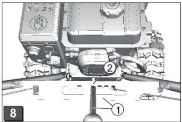
- Guide the pre-assembled drive speed selection lever through the drive speed selection plate (8-1).
- Remove the mounting screw from the connection bolt and attach the drive speed selection lever (9).
- Secure the drive speed selection lever with the horizontal mounting screw (☐ 10-1). Do not tighten the screw yet.
- Adjust the lever position with the adjustment screw so that it engages into the slot for the first speed setting (1) (☐ 8-2).
- Lock the adjustment screw ( 10-2).
- Tighten the mounting screw with the self-locking nut (10-1).
»The drive speed selection lever is attached.
Attaching the snow discharge chute
- Lightly lubricate the surface of the snow discharge chute that slides against the snow blower with spray oil (☐ 11).
- Mount the discharge chute ( 11).
-
Insert mounting screws into the lower, larger guide plate and attach the smaller guide plate (☐ 12-1).
-
Insert the guide plates into the discharge chute from beneath and tighten with the self-locking nuts (12-1).
- Repeat the procedure for the other two guides »The snow discharge chute is attached.
Attaching snow discharge chute hand crank
- Remove the handle from the crank by removing the mounting screw (☐ 13).
- Insert the hand crank from the handle side from below into the guide on the guide handle (☐ 14).
- Remove the safety split pin and washer underneath using pliers (15).
- Insert the hand crank into the lower guide on the snow discharge chute. The snow discharge chute must be positioned such that the spiral of the hand crank fits into the grooves of the chute (16-1). If it is difficult or impossible to move the hand crank to the lower guide, it may be necessary to adjust the upper guide. To do this, loosen the screws slightly and re-tighten after adjusting (14-1).
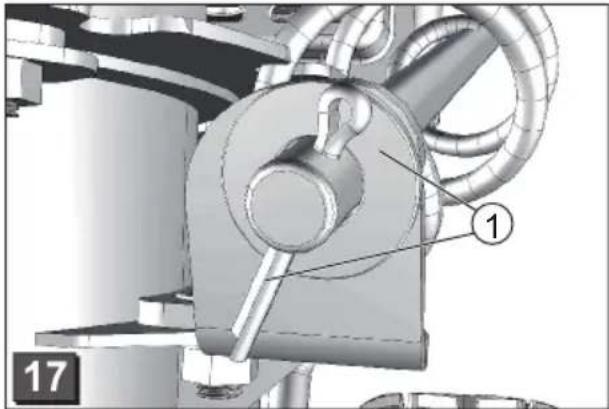
- Attach the washer and insert the safety split pin using pliers (17-1).
- Bend the ends of the safety split pin ( 18).
- Screw the handle onto the crank ( 19).
»The hand crank is attached.
Checking the tyre pressure
The maximum allowed tyre pressure is indicated on the tyres (20-1). Note: 1 bar = approximately 14.5 psi
Pump up both tyres to the same pressure level using the tyre pump.
Attaching the headlight (620E II)
- Insert the pre-assembled headlight from the front through the guide handle using the mounting screw (21-1). Do not twist or damage the cable!
- Fasten the headlight using the washer and self-locking nut.
- Fasten the cable to the guide handle using cable clips.
»The headlight is attached.
Adding fuel and engine oil

Always follow the instructions in the engine operating manual provided.
Fuel the snow blower and add oil before use.

Danger - fire hazard!
Petrol and oil are highly flammable!
Fuel and lubricant
| Petrol Engine oil | ||
| Type Regular | lead-free petrol (86 octane or higher)Engine is E10-compliant. | SAE 5W-30 recommended |
| Filling quantity | See engine manual | |
Safety

Warning!
Never leave the engine running in an enclosed space. Risk of poisoning!
■ Store petrol and oil only in appropriate containers.
- Allow the machine to cool before storing it in an enclosed space.
If there is still petrol in the tank, make sure that there is no ignition source in the enclosed space, such as a heater or clothes dryer.
■ Add or empty petrol and oil in an open space only when the engine is switched off and cold.
■ Do not overfill the tank (petrol expands).
■ Do not smoke while filling the tank.
■ Do not open the tank cap while the engine is running or hot.
■ Replace the tank or cap if damaged.
■ Always secure the tank cap securely.
■ If petrol has spilled out:
Do not start the engine
Do not attempt ignition
- Collect spilled petrol with a binding agent or cloth and dispose of appropriately.
Clean the machine
■ If engine oil has spilled out:
Do not start the engine
- Collect spilled petrol with an oil binding agent or cloth and dispose of appropriately.
Clean the machine

When disposing of used oil:
- do not throw into the rubbish
- do not pour into sewers or drains or onto the ground
We recommend returning used oil in a closed container to a recycling facility or service centre.
Adding engine oil
- Remove the oil cap (22-1) and store in a clean area.
- Add oil using a funnel.
- Check the oil level.
- Replace the oil cap tightly and clean.
See the engine manual for information about checking the oil level.
Adding petrol
- Remove the tank cap (22-2) and store in a clean area.
- Add petrol using a funnel.
- Replace the tank cap tightly and clean.
Getting ready for operation

Caution!
Do not operate a damaged machine! Perform a visual inspection before using.

The camera symbol on the following pages references the illustrations on pages 4–7.
Adjusting the clearance height

Danger - risk of injury!
Adjust the clearance height only if the engine is switched off and the auger is not in motion!

- Adjust the clearance height to avoid taking in gravel or other objects.
-
Look out for uneven places such as ruts, manhole covers or paving stones.
-
Place the machine on an level surface.
- Loosen the left and right skid plate clamping screws (☐ 23-1).
- Raise the clearing plate to the desired height and attach the skid plates. Make sure that both skid plates are spaced equally so that the clearing plate runs parallel to the ground (23-2).

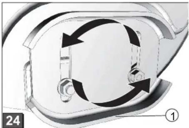
- If the skid plates are worn (sliding edge
(24-1) worn through, turn 180irc and use the other side (24). - See the replacement parts list when ordering replacements.
Checking the tyre pressure
Check the tyre pressure before the first use in winter and then at least once every three months during the period of use.
The maximum allowed tyre pressure is indicated on the tyres (20-1). Note: 1 bar = approximately 14.5 psi
Inspecting the machine
Each time before starting, check to make sure that the four shear pins (☐ 25-1) are intact.
Replace broken shear pins with original replacement parts. Using unauthorised replacement parts may cause severe damage to the machine! See the replacement parts list when ordering replacements.
Check all controls, safety devices, nuts, screws and bolts on the machine to make sure that they are firmly secured and in good condition, and and that no parts are missing.
Starting the engine

Danger - risk of poisoning!
Never leave the engine running in an enclosed space.
Position indicators:
| ChokeCLOSE OPEN |  |
| GasFast Slow |  |
| Engine keyOff On |  |
| Fuel tap ClosedOpen |  |
| ntPrimer button |  |
Starting procedure
- Check the oil and fuel levels.
- Open the fuel tap ( 27).
- Set the choke to ON ( 27-1).
- Press the primer button 3 times at 2-second intervals(☐ 28-1). In temperatures under 10 °C, press the primer button 5 times.
- Move the throttle to the Fast position ( 29).
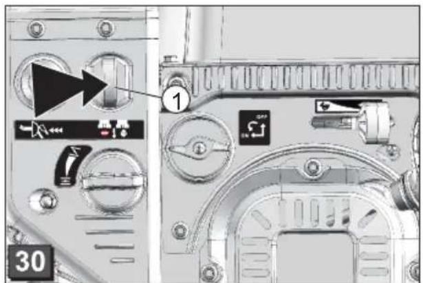
- Insert the engine key ( 30-1).
■ Starting manually:
- Pull the starter rope lightly until you feel resistance, then pull out briskly and allow the rope to return slowly (31).
230 V Starting procedure (620E II)
1.

natural_image
Pure electrical connector symbols without any text or labels2.

natural_image
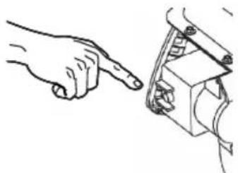
Line drawing of a hand pointing at a mechanical component (no text or symbols)Switching off the engine
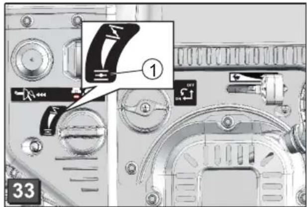
- Set the throttle to Slow (34).
In order to prevent freezing, continue running the auger and impeller until they are mostly free of snow.
-
Turn the engine key to Stop and remove ( 35-1). »The engine switches off.
-
Turn the fuel tap to the Closed position ( 35).

Danger: risk of severe injury!
The engine may coast down. After switching off, make sure that the engine is at a standstill.
Operation

Danger - risk of injury!
Wear work clothing and protective gear.
- Winter clothing
- Non-slip winter shoes
- Eye protection (safety glasses or visor)
- Hearing protection
Starting operation
- Prepare the snow blower for operation.
- Check the position of the snow discharge chute and
■ adjust the discharge direction using the hand crank (36-1).
■ adjust the discharge height(36-2).
-
Start the engine.
-
Set the wheel drive speed ( 36-3):
The forward speeds range from 1 to 5, 1 being the slowest speed and 5 the fastest speed.
The reverse speeds are R1 and R2, R1 being the slower speed and R2 the faster speed.
- Press the auger drive clutch lever ( 37).

Danger: risk of severe injury!
Keep away from the augers while they are in motion. Keep other persons or animals away.
- Press the wheel drive clutch lever ( 37).
»The snow blower starts moving.
Stopping operation
- Release (disengage) the auger and wheel drive clutch levers (38-1).
In order to prevent freezing, continue running the auger and impeller until they are mostly free of snow.
»The snow blower stops moving and the auger and impeller stop running.
Changing the wheel drive speed
- Release (disengage) the auger and wheel drive clutch levers (38-1).
- Change the drive speed only when disengaged in order to avoid damaging the machine.
- Change the drive speed using the speed selector (38-2).
Unclogging the snow discharge chute
If snow does not discharge properly, the augers or the discharge chute may be clogged with snow or ice.
- Release (disengage) the auger and wheel drive clutch levers (38-1).
- Switch off the engine.
- Disconnect the spark plug connector.
- Carefully remove the snow from the discharge chute and auger using the snow cleaning tool (39-1).
If snow still does not discharge properly, contact a qualified workshop.
Maintenance and care

Danger - risk of injury!
- Before performing any maintenance or service, always switch off the engine and disconnect the spark plug connector.
- The engine may coast down. After switching off, make sure that the engine is at a standstill.
■ Clean the machine after every use. Be especially sure to remove residual de-icing salt.
■ Do not hose down the unit with water!
Water penetration may cause malfunctions (ignition system, carburettor).
■ Replace the silencer if defective.
■ Follow the maintenance schedule.
■ Follow the instructions in the engine manual.
Maintenance schedule
After the first 5 hours of operation
■ Change the engine oil (see engine manual).
Before each use
- Check the oil level (see engine manual).
- Check the shear pins.
- Check machine for damage.
Every three months
- Check the tyre pressure.
Lubricate the snow discharge chute ring with spray oil (☐ 11).
Annually
- Replace spark plug (see engine manual).
Lubricate auger.
Lubricating the auger
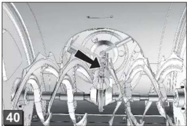
Using a grease gun, inject 2 to 3 shots of universal grease into the grease nipple (☐ 40).
Maintaining the wheel drive
Adjusting the control cable
If the wheel drive no longer engages when the engine is running, the control cable must be adjusted.

Caution!
- Switch off the engine before adjusting the control cable.
-
If the wheel drive mechanism cannot be disengaged, switch off the engine. Do not attempt repair; contact a qualified workshop.
-
Loosen the lock nut ( 41-1).
-
Turn the adjustment on the control cable in the direction of the arrow (☐ 41-2) until the control cable does not sag (i.e. is somewhat taut) when the clutch lever is pressed. Hold the cable while tightening so that it does not twist.
-
Tighten the lock nut.
- Check the adjustment by starting the engine and engaging the wheel drive.
- If the wheel drive still does not engage and disengage properly, have the machine repaired by a qualified workshop.
Maintaining the auger drive
Adjusting the control cable
If the auger drive no longer engages when the engine is running, the control cable must be adjusted.

Caution!
- Switch off the engine before adjusting the control cable.
-
If the auger drive mechanism cannot be disengaged, switch off the engine. Do not attempt repair; contact a qualified workshop.
-
Loosen the lock nut ( 41-1).
- Turn the adjustment on the control cable in the direction of the arrow (☐ 41-2) until the control cable does not sag (i.e. is somewhat taut) when the clutch lever is pressed. Hold the cable while tightening so that it does not twist.
- Tighten the lock nut.
- Check the adjustment by starting the engine and engaging the auger drive.
- If the auger drive still does not engage and disengage properly, have the machine repaired by a qualified workshop.
Replacing the shear pins
If the auger is blocked, the shear pins (☐ 25-1) may break in order to ensure safe operation.

- Replace broken shear pins with original replacement parts. Using unauthorised replacement parts may cause severe damage to the machine!
-
See the replacement parts list when ordering replacements.
-
Switch off the machine and disconnect the spark plug connector.
-
Remove damaged shear pins ( 42-2).
-
Check the shaft for damage.
-
Insert new shear pins and secure with safety split pins (☐ 42-1)..
Storage
If the machine is stored for a long period of time, for example, after the winter season, heed the following:

Danger - risk of explosion!
Do not store the machine near an open flame or heat source.
■ Empty the carburettor.
Start the engine.
Close the fuel tap.
- Wait until the engine dies.
■ Allow the engine to cool.
■ Store in a dry area that is inaccessible to children and unauthorised persons.
■ Either empty the petrol tank or fill it completely.
■ Remove the engine key.
■ Disconnect the spark plug connector.
Repairs
Repairs may be performed only by qualified workshops. Have a qualified workshop perform and inspection:
■ After running onto an obstacle.
■ If the engine stops suddenly.
■ If the auger or impeller is damaged.
Disposal

Do not dispose of worn-out machines, batteries or rechargeable batteries in the household rubbish!
Packaging, device and accessories are made of recyclable materials and are to be disposed of accordingly.
Troubleshooting

Caution!
Before troubleshooting, always switch off the engine and disconnect the spark plug connector.
| Problem Solution | |
| Engine does not start. • Add petrol. | • Set throttle to "Start".• Open the choke, push the primer button.• Check the spark plugs and replace if necessary. |
| Engine performance is diminished. | • Clean discharge chute/housing.• Remove snow and ice from auger and impeller.• Reduce operating speed. |
| Wheel drive does not work when clutch lever is pressed. | • Adjust control cable.• Contact the customer service workshop. |
| Wheel drive cannot be stopped (does not disengage). | • Switch off the engine.• Do not attempt repair!• Contact the customer service workshop. |
| Auger does not turn when clutch lever is pressed. | • Shear pin is broken, replace.• Adjust control cable.• Contact the customer service workshop. |
| Auger drive cannot be stopped (does not disengage). | • Switch off the engine.• Do not attempt repair!• Contact the customer service workshop. |
| Machine vibrates excessively. • Check auger and impeller. | |
| Machine pulls to one side. • Check the tyre pressure and inflate.• Check the skid plates; adjust or replace. |

If problems are not listed in this table or you are unable rectify them yourself, please consult our customer service department.
Warranty
We will address claims for any defects in materials and workmanship during the statutory period of limitation by means of repairs or replacements of our choice. The period of limitation is governed by the laws of the country in which the machine was purchased.
Our warranty applies only if: The warranty is no longer in effect if:
■ The machine has been properly handled
■ Efforts have been made to repair the machine
■ The operating instructions have been adhered to
■ Technical modifications have been made to the machine
■ Original replacement parts have been used
■ The machine was assembled incorrectly
■ The machine has not been used for its intended purpose
The warranty does not cover:
■ Damage to paint work through normal use
■ Parts subject to wear as indicated in the replacement parts list with a box XXX XXX (X)
Internal combustion engines – separate warranty conditions of the respective engine manufacturer apply
The warranty period begins with the purchase by the first buyer. The warranty period begins on the date that appears on the original purchase receipt.
In the event of a warranty claim, please your contact supplier or the nearest authorised customer service centre with this warranty declaration and the purchase receipt in hand. This warranty does not affect the legal warranty claims by the purchaser against the seller.
EC declaration of conformity
We hereby declare that this product, in the form in which it is marketed, meets the requirements of the harmonised EU guidelines, EU safety standards, and the product-specific standards.
Product
Snow Blower
Serial number
G4224235
Model
Snow Line 560 II
Snow Line 620 II
Snow Line 620E II
Sound power level
measured / guaranteed
98 / 100 dB(A)
Manufacturer
AL-KO Geräte GmbH
Ichenhauser Str. 14
89359 KOETZ
DEUTSCHLAND
EU directives
2006/42/EG
(+2009/127/EG)
2004/108/EG
2000/14/EG
Conformity evaluation
2000 /14/EG
Appendix 5
Executive Officer
Anton Eberle
Ichenhauser Str. 14
89359 KOETZ
DEUTSCHLAND
Harmonised standards
EN ISO 12100-1
EN ISO 12100-2
EN ISO 14982
ISO 8437
Kötz, 2012-06-04

Antonio De Filippo, Managing Director
natural_image
Illustration showing three different electrical connector configurations: a cable connector, a plug-in socket, and a hand pointing to a terminal block (no text or symbols present)Antonio De Filippo, Managing Director
natural_image
Pure electrical connector diagrams without any text or symbols2.

natural_image
Line drawing of a hand pointing at a mechanical component (no text or symbols)Antonio De Filippo, Managing Director
O tem priročniku
Opis izdelka (OA)
natural_image
Illustration of three different electrical switch components: a motor, a plug-in socket, and a hand operating a terminal block (no text or symbols present)Izklop motorja
- Plinsko ročico postavite v položaj počasi (34).

Antonio De Filippo, Managing Director
O ovom priručniku
- Prije ugradnje pročitajte ovu dokumentaciju. To je preduvjet za siguran rad i rukovanje bez smetnji. Prije uporabe se upoznajte s elementima za rukovanje i uporabom stroja.
■ Pridržavajte se sigurnosnih napomena i upozorenja u ovoj dokumentaciji i na uređaju.
■ Ova je dokumentacija stalni sastavni dio opisanoga proizvoda i u slučaju prodaje treba je predati kupcu.
Objašnjenje znakova

Pozor!
Pregled proizvoda (OA)
natural_image
Pure electrical connector symbols without any text or labels2.

natural_image
Line drawing of a hand pointing at a mechanical component (no text or symbols)Antonio De Filippo, Managing Director
О овом приручнику
Преглед производа (CA)
natural_image
Pure electrical connector diagrams without any text or symbols2.
natural_image
Line drawing of a hand pointing at a mechanical component (no text or symbols)Угасите мотор
Antonio De Filippo, Managing Director
natural_image
Three mechanical components with an upward arrow, no visible text or symbols2.

natural_image
Line drawing of a hand pointing at a mechanical component (no text or symbols)Wyłączanie silnika
Antonio De Filippo, Managing Director
CZ
K této příručce
natural_image
Pure electrical connector symbols without any text or labels2.
natural_image
Line drawing showing a hand pointing at a mechanical component (no text or symbols)Vypnutí motoru
- Nastavte páku plynu do polohy Pomalu (34).

Antonio De Filippo, Managing Director
Prehl'ad produktu (OA)
natural_image
Illustration of three different electrical components: a remote control unit, a plug-in socket, and a hand interacting with a terminal block (no text or symbols present)Vypnutie motora
- Páku plynu nastavte do polohy pomaly (34).

Antonio De Filippo, Managing Director
A kézikönyvröl
natural_image
Three mechanical components with no visible text or symbols2.

natural_image
Line drawing of a hand pointing at a mechanical component (no text or symbols)Antonio De Filippo, Managing Director
Om denne håndbog
Produktoversigt (94)
Advarsel – brandfare!
Advarsel – brandfare!
natural_image
Pure electrical circuit lines without any symbols2.

natural_image
Line drawing of a hand pointing at a mechanical component (no text or symbols)Slukning af motoren
- Stil gashåndtaget i position Langsomt (34).

Antonio De Filippo, Managing Director
Om denna handbok
Produktöversikt (A)
natural_image
Illustration of three different electrical connector components: a switch, a hand pointing to a terminal block, and a plug inserted into a socket (no text or symbols present)Antonio De Filippo, Managing Director
Om denne håndboken
Produktoversikt (A)
Montere lys (620E II)
natural_image
Pure electrical connector diagrams without any text or symbols2.

natural_image
Line drawing of a hand pointing at a mechanical component (no text or symbols)Slå av motoren
Stille inn Bowdendrag
Stille inn Bowdendrag
Antonio De Filippo, Managing Director
Laitteen osat (9)
natural_image
Illustration of three different electrical connector components: a cable, a switch, and a hand pointing to a terminal block (no text or symbols present)Antonio De Filippo, Managing Director
Selle juhendi kohta
Monteerimine.... 193
Toote ülevaade (OA)
Tule monteerimine (620E II)
natural_image
Pure electrical connector diagrams without any text or symbols2.

natural_image
Line drawing showing a hand pointing at a mechanical component (no text or symbols)Antonio De Filippo, Managing Director
Pärskats pär produktiem (CA)
natural_image
Three mechanical components with arrows indicating direction (no text or symbols)2.
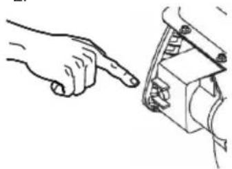
natural_image
Illustration of a hand pointing at a mechanical component (no text or symbols present)Motora izslēgšana
- Akseleratoru iestatiet uz langsam (lēni) (34).

Antonio De Filippo, Managing Director
Šiame žinyne
Produkto apžvalga (OA)
natural_image
Three mechanical components with an upward arrow, no visible text or symbols2.

natural_image
Line drawing of a hand pointing at a mechanical component (no text or symbols)Variklio išjungimas
Antonio De Filippo, Managing Director
Обзор изделия (OA)
natural_image
Pure electrical connector diagrams without any text or symbols2.

natural_image
Line drawing of a hand pointing at a mechanical component (no text or symbols)Antonio De Filippo, Managing Director
Про цей довідник
Огляд виробу (OA)
natural_image
Pure electrical circuit lines without any symbols2.

natural_image
Line drawing of a hand pointing at a mechanical component (no text or symbols)Вимкнення двигуна
Antonio De Filippo, Managing Director
За този наръчник
Преглед на продукта (CA)
natural_image
Pure electrical connector symbols without any text or labels2.

natural_image
Line drawing showing a hand pointing at a mechanical component (no text or symbols)Antonio De Filippo, Managing Director
natural_image
Pure electrical connector symbols without any text or labels2.

natural_image
Line drawing of a hand pointing at a mechanical component (no text or symbols)Oprirea motorului
Antonio De Filippo, Managing Director
AL-KO
Country Company Telephone Fax
A AL-KO KOBER Ges.m.b.H. (+43)3578/2515-100 (+43)3578/2515-31
AUS AL-KO INTERNATIONAL Pty. Ltd. (+61)3/9767-3700 (+61)3/9767-3799
B / L Eurogarden NV (+32)16/805427 (+32)16/805425
BG Valerii S&M Group SJ (+359)2 942 34 02 (+359)2 942 34 10
CH AL-KO KOBER AG (+41)56/418-31 53 (+41)56/4183160
CZ AL-KO KOBER Spol. S.R.O. (+420) 382/210381 (+420) 382/212782
D AL-KO GERÄTE GmbH (+49)8221/203-0 (+49)8221/203-138
DK AL-KO GINGE A/S (+45)98821000 (+45)98825454
EST/LT/LV SIA AL-KO KOBER (+371)67/627-326 ((+371)67/807-018
F AL-KO S.A.S. (+33)3/8576-3500 (+33)3/8576-3581
GB Rochford Garden Machinery Ltd. (+44)1963/828050 (+44)1963/828052
H AL-KO KFT (+36)29/5370-50 (+36)29/5370-51
HR Brun.ko.-prom d.o.o. (+385)1 3096 567 (+385)1 3096 567
I AL-KO KOBER GmbH / SRL (+39)039/932 9-311 (+39)039/932 9-390
IN AGRO-COMMERCIAL (+91)3322874206 (+91)3322874139
IQ Gulistan Com (+946)750 450 80 64
IRL Cyril Johnston & Co. Ltd. (+44)2890813121 (+44)2890914220
LY ASHOFAN FOR AGRICULT. ACC. (+218)512660209 (+218)512660209
MA BADRA Sarl (+212)022447128 (+212)022447130
MK Techno Geneks (+389)2 2551801 (+389)2 2520175
N AL-KO GINGE A/S (+47)64/86-2550 (+47)64/86-2554
NL O.DE LEEUW GROENTECHNIEK (+31)38/444 6160 (+31)38/444 6358
PL AL-KO KOBER Sp. z.o.o. (+48)61/816-1925 (+48)61/816-1980
RO OMNITECH Technology SRL (+4)021 326 36 72 (+4)021 326 36 79
RUS 000 AL-KO KOBER (+7)499/16887-16 (+7)499/96600-00
RUS ZAO AL-KO St. Petersburg GmbH (+7)812/446-1075 (+7)812/446-1075
S GINGE Svenska AB (+46)31/57-3580 (+46)31/57-5620
SK AL-KO KOBER Slovakia Spol. S.R.O. (+421)2/4564-8267 (+421)2/4564-8117
SLO Darko Opara s.p. (+386)1 722 58 50 (+386)1 722 58 51
SRB Agromarket d.o.o. (+381)34 308 000 (+381)34 308 16
TR ZIMAS A.S. (+90)232 4580586 (+90)232 4572697
UA TOV AL-KO KOBER (+380)44/492 33-96 (+380)44/496 66-93



- AL-KO SCHNEEFRÄSE
- Snow Line 560 II, 620 II, 620E II
- Zu diesem Handbuch
- Motor ausschalten
- About this manual
- Meaning of symbols
- Caution!
- Contents
- Description of product
- Intended use
- Incorrect use
- Safety and protective devices
- Danger - risk of injury!
- Clutch lever
- Adjustable snow discharge chute
- Delivery contents
- SSafety instructions
- Assembly
- Required tools
- Assembly sequence
- Attaching and adjusting control cables
- Attaching the drive speed selection lever
- Attaching the snow discharge chute
- Attaching snow discharge chute hand crank
- Checking the tyre pressure
- Attaching the headlight (620E II)
- Adding fuel and engine oil
- Fuel and lubricant
- Safety
- Warning!
- Adding engine oil
- Adding petrol
- Getting ready for operation
- Adjusting the clearance height
- Inspecting the machine
- Starting the engine
- Starting procedure
- ■ Starting manually:
- V Starting procedure (620E II)
- Switching off the engine
- Danger: risk of severe injury!
- Operation
- Starting operation
- Stopping operation
- Changing the wheel drive speed
- Unclogging the snow discharge chute
- Maintenance and care
- Maintenance schedule
- After the first 5 hours of operation
- Before each use
- Every three months
- Annually
- Lubricating the auger
- Maintaining the wheel drive
- Adjusting the control cable
- Maintaining the auger drive
- Replacing the shear pins
- Storage
- Danger - risk of explosion!
- Repairs
- Disposal
- Do not dispose of worn-out machines, batteries or rechargeable batteries in the household rubbish!
- Troubleshooting
- Warranty
- EC declaration of conformity
- Product
- Serial number
- Model
- Sound power level
- Manufacturer
- EU directives
- Conformity evaluation
- Executive Officer
- Harmonised standards
- O tem priročniku
- Izklop motorja
- O ovom priručniku
- Objašnjenje znakova
- Pozor!
- О овом приручнику
- Угасите мотор
- Wyłączanie silnika
- CZ
- K této příručce
- Vypnutí motoru
- Vypnutie motora
- A kézikönyvröl
- Om denne håndbog
- Advarsel – brandfare!
- Slukning af motoren
- Om denna handbok
- Om denne håndboken
- Montere lys (620E II)
- Slå av motoren
- Stille inn Bowdendrag
- Selle juhendi kohta
- Tule monteerimine (620E II)
- Motora izslēgšana
- Šiame žinyne
- Variklio išjungimas
- Про цей довідник
- Вимкнення двигуна
- За този наръчник
- Oprirea motorului
- AL-KO
Brand : AL-KO
Model : SnowLine 620 II
Category : Snow blower