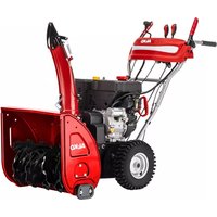
SnowLine 620.4 E III LED - Snow blower AL-KO - Free user manual and instructions
Find the device manual for free SnowLine 620.4 E III LED AL-KO in PDF.



| Product type | Snow blower (snow thrower) |
| Brand | AL-KO |
| Model | SnowLine 620.4 E III LED |
| Clearing width | 62 cm (estimated based on model) |
| Adjustable clearing height | Yes, via adjustable skid shoes |
| Engine | Petrol, 4-stroke, manual and 230 V electric start |
| Engine power | Not explicitly specified, approx. 5 to 7 HP (estimated) |
| Fuel tank capacity | Not explicitly specified, approx. 3.5 L (estimated) |
| Engine oil capacity | Not explicitly specified, approx. 0.6 L (estimated) |
| Speeds | 6 forward + 2 reverse, gear lever |
| Drive system | Worm gear transmission, Bowden cables |
| Discharge chute | Manually adjustable orientation, adjustable height with deflector |
| Lighting | Integrated LED, turns on automatically when starting |
| Heated handles | Yes, with switch |
| Weight | Approx. 65-70 kg (estimated) |
| Recommended tire pressure | Indicated on tire (max 1 bar ≈ 14.5 psi) |
| Safety devices | Clutch levers (2), shear bolts, engine kill switch |
| Delivery contents | Snow thrower, handlebars, control panel, discharge chute, keys, spare bolts, manuals |
| Maintenance | Lubricating worm gear, oil change, bolt inspection, cable adjustment |
| Intended use | Clearing fresh snow on paved surfaces (private domain) |
| Warranty | Statutory, wear parts excluded |
Frequently Asked Questions - SnowLine 620.4 E III LED AL-KO
User questions about SnowLine 620.4 E III LED AL-KO
0 question about this device. Answer the ones you know or ask your own.
Ask a new question about this device
Download the instructions for your Snow blower in PDF format for free! Find your manual SnowLine 620.4 E III LED - AL-KO and take your electronic device back in hand. On this page are published all the documents necessary for the use of your device. SnowLine 620.4 E III LED by AL-KO.
USER MANUAL SnowLine 620.4 E III LED AL-KO
SnowLine 620.4 E III LED
natural_image
Technical line drawing of a snowman with visible blades and wheels (no text or symbols)






Inhaltsverzeichnis
Deutsch 12
English....28
Français....43
Italiano....60
Slovenščina 76
Hrvatski....91
Српски....106
Polski 122
Česky 139
Slovenská 154
Magyarul....170
Dansk 186
Svensk....201
Norsk 216
Suomi 230
Eesti 245
Lietuvių 260
Latviešu 275
Român 290
български 306
Русский 323
Україна....341
© 2023
AL-KO KOBER GROUP Kötz, Germany
This documentation or excerpts therefrom may not be reproduced or disclosed to third parties without the express permission of the AL-KO KOBER GROUP.


natural_image
Mechanical assembly diagram showing a component with numbered callouts (1), no readable text or symbols present.















natural_image
Mechanical component with numbered annotation (1) showing a pin inserted into a housing (no text or symbols present)

| SnowLine 620.4 E III LED | |
 | 114036 |
 | 4IPetrol / unleaded ≥ 86 octane, E10 |
 | 0,95IRecommendation: SAE 5W-30 |
 | Loncin LC180FDS |
 | 302 cm3 |
 | 6,2 kW / 3600 min-1 |
 | 2000 +/- 200 min-1 |
 | 134 x 62 x 113 cm |
 | 96 kg |
 | 62 cm |

SnowLine 620.4 E III LED

51 cm

3,8 km/h +/- 0,3
1,9 km/h +/- 0,3

a_h = 4,5m / s^2
K = 1,5 ~m / s^2

L_pA = 90,6dB(A)
K = 2,5 dB(A)

L_wA=102 dB(A)

33,02 cm / 13"
natural_image
Two abstract line drawings: one with a downward arrow and the other with a wavy line (no text or symbols)
natural_image
Simple line drawing of a hand holding a device with a circular button, no text or symbols present
Symbol Bedeutung
natural_image
Diagram of a mechanical device with directional arrows indicating motion or force (no text or symbols)natural_image
Diagram showing three curved pipe fittings with directional arrows indicating movement or flow (no text or symbols)natural_image
Diagram showing two types of electrical connectors: a cylindrical device with a handle and a plug with a cable, and a separate plug with an arrow indicating direction (no text or symbols present)- (36/b)

natural_image
Illustration of a hand pointing to a mechanical component (no text or symbols)6.8 Motor stoppen (37, 38)
1 About these operating instructions...... 28
1.1 Symbols on the title page 29
1.2 Legends and signal words.... 29
2 Product description 29
2.1 Designated use.... 29
2.2 Possible foreseeable misuse.... 29
2.3 Safety and protective devices...... 29
2.4 Scope of supply 30
2.5 Symbols on the appliance.... 30
2.5.1 Safety signs.... 30
2.5.2 Operating signs 31
2.6 Product overview (01).... 31
3 Safety instructions.... 32
3.1 Safety instructions in accordance with ISO 8437, Annex A.... 32
3.2 Safety instructions relating to operation.... 34
3.3 Handling of petrol and oil.... 34
4 Unpacking appliance (02) 35
5 Assembly.... 35
5.1 Fitting the lower brace (03, 04)...... 35
5.2 Fitting the operating panel (05)...... 35
5.3 Installing and adjusting Bowden cables for travel and worm drives (06 - 11).... 35
5.4 Adjusting the Bowden cable (12)..... 36
5.5 Checking the Bowden cable setting (13) 36
5.6 Mounting the rod for the gear selector lever (14, 15) ...... 36
5.7 Installing the flexible shaft for the snow discharge spout (16, 17).... 36
5.8 Plugging in the heater and lighting plug (18).... 36
5.9 Fitting the snow discharge spout (19-22).... 36
5.10 Connecting the Bowden cable to the discharge flap (23).... 37
5.11 Attaching the Bowden cable (24)..... 37
6 Start-up.... 37
6.1 Operating material.... 37
6.2 Filling with engine oil (25).... 37
6.3 Filling with petrol (25) 37
6.4 Checking the tyre pressure (26)...... 37
6.5 Adjusting the clearing height (27 - 29) 38
6.6 Checking the shear pins on the appli-
ance (30, 46) 38
6.7 Starting the engine (31 - 36) ...... 38
6.8 Stopping the engine (37, 38).... 39
7 Operation.... 39
7.1 Starting clearing (39 - 41).... 39
7.2 Stopping clearing (42) 39
7.3 Changing gear for the travel drive (41 - 43).... 39
7.4 Clearing clogging in the snow discharge spout (42, 44) .... 39
8 Repair 40
9 Maintenance and care 40
9.1 Maintenance schedule 40
9.2 Greasing the transport auger (45)..... 40
9.3 Servicing the travel and auger drives (08)....40
9.4 Replacing the shear pins (30, 46) ..... 41
10 Help in case of malfunctions.... 41
11 Storage.... 41
12 Disposal.... 42
13 After-Sales/Service.... 42
14 Information on the Declaration of Confor-
mity 42
15 Guarantee.... 42
1 ABOUT THESE OPERATING INSTRUCTIONS
The German version is the original operating instructions. All additional language versions are translations of the original operating instructions.
- Keep these operating instructions in a safe place at all times so that they can be consulted if you need any information about the appliance.
■ Only pass on the appliance to other persons together with these operating instructions.
■ Comply with the safety and warning information in these operating instructions.
1.1 Symbols on the title page
Symbol Meaning

It is essential to read through these operating instructions carefully before start-up. This is essential for safe working and trouble-free handling.

Operating instructions

Never operate the petrol powered device in the vicinity of open flames or heat sources.
1.2 Legends and signal words
⚠️ DANGER! Denotes an imminently dangerous situation which will result in fatal or serious injury if not avoided.
WARNING! Denotes a potentially dangerous situation which can result in fatal or serious injury if not avoided.
CAUTION! Denotes a potentially dangerous situation which can result in minor or moderate injury if not avoided.
IMPORTANT! Denotes a situation which can result in material damage if not avoided.
i NOTE Special instructions for ease of understanding and handling.
2 PRODUCT DESCRIPTION
2.1 Designated use
The snow blower is suitable exclusively for clearing freshly fallen, loose wet and powder snow on paved paths and areas such as patios, garage entrances, footpaths or car parking spaces in the private sector. The paths and areas to be cleared must have a solid substrate and a smooth sur-
face, e.g. concrete paving, granite paving or asphalt.
This appliance is intended solely for use in non-commercial applications. Any other use as well as unauthorised conversions or modifications are regarded as contrary to the intended use and will result in voiding of the warranty as well as loss of conformity; the manufacturer will thus decline any responsibility for damage and/or injury suffered by the user or third parties.
2.2 Possible foreseeable misuse
The snow blower is not suitable for clearing unpaved paths and areas – e.g. gravel surfaces, gravel paths or meadows. Snow in large quantities and depths, very wet snow and hard-packed snow and ice can no longer be cleared with this appliance.
The tool is designed neither for commercial use in public parks and sports facilities, nor for use in farming and forestry.
2.3 Safety and protective devices
WARNING! Risk of injury. Defective and disabled safety and protective devices can result in serious injury.
■ Have any defective safety and protective devices repaired.
■ Never disable safety and protective devices.
Clutch lever
The appliance has two clutch levers on the handlebar. In the event of danger, release both clutch levers.
■ Clutch lever for the auger drive of the snow discharge spout. Auger drive is stopped.
■ Clutch lever for the travel drive. Travel drive is stopped.
Adjustable snow discharge spout
Adjust the snow discharge spout so that persons and animals are not endangered and buildings, vehicles and other objects cannot be damaged by the discharged snow. When working on public roads, take care, not to hinder the road traffic or endanger other road users.
2.4 Scope of supply

The items listed here are included in the standard scope of supply. Check that all items are present:
No. Component
| 1 Snow blower |
| 2 Lower brace |
| 3 Operating panel with upper brace |
| 4 Snow discharge spout |
| 5 Operating instructions for the snow blower |
| 6 Operating instructions for the engine |
| 7 Attachment kit for snow discharge spout (x3) |
| 8 Spark plug spanner |
| 9 Engine key (x2) |
| 10 Spare shear pins (x4) |
| 11 Cotter pins (x4) |
| 12 Rod for gear selector lever |
| 13 Flexible shaft for snow discharge spout |
2.5 Symbols on the appliance
2.5.1 Safety signs
Symbol Meaning
 | Important!Pay special attention when handling this product! |
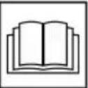 | Read the operating instructions before starting operation! |
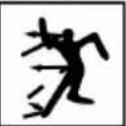 | Keep away from the discharge area. Danger from discharged snow. |
 | Wear safety goggles and ear protectors! |
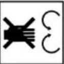 | Do not reach into rotating parts. Risk of entanglement! |
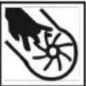 | Do not reach into the snow discharge spout! |
 | Do not reach or step into the transport auger! |
 | Switch off the engine before starting any work on the appliance. |
 | Remove the spark plug connector before maintenance and repair work. |
 | Keep other people out of the danger area! |
 | Rotating parts in the discharge area! Risk of entanglement! |
2.5.2 Operating signs
| Symbol Meaning | |
| ChokeCLOSE / OPEN |  |
| ThrottleSlow / Fast | 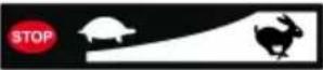 |
| Engine keyOn / Off |  |
| Fuel cockOFF (closed)ON (open) |  |
| Primer button |  |
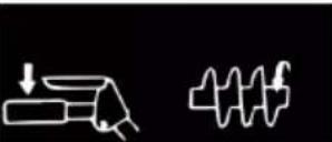
| Auger driveStart / stop | 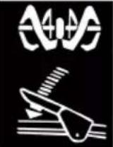 |
 | |
 | |
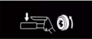
| Travel driveStart / stop |  |
 | |
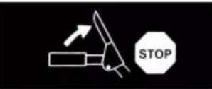 |
Symbol Meaning
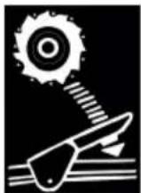
Align snow discharge spout with crank
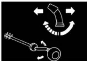
natural_image
Diagram of a mechanical device with directional arrows indicating motion or force (no text or symbols)Adjust snow discharge height with lever
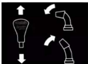
natural_image
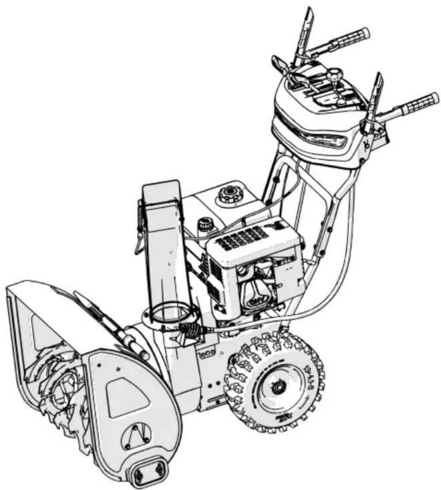
Diagram showing three curved pipe fittings with directional arrows indicating flow or movement (no text or symbols)2.6 Product overview (01)
The product overview (01) gives an overview of the appliance.
| No. | Component |
| 1 | Heated handles |
| 2 | Clutch lever for the auger drive |
| 3 | Clutch lever for the travel drive |
| 4 | Hand crank for adjusting the discharge direction |
| 5 | Lever for adjustment of the discharge height |
| 6 | Gear selector lever, 6 forward and 2 reverse gears |
| 7 | Handle heater switch |
| 8 | Spare shear pins |
| 9 | Deflector on snow discharge spout for setting the discharge height |
| 10 | Snow discharge spout with guard |
| 11 | Lights |
| 12 | Tank cap |
| 13 | Oil filler cap |
| 14 | Plough |
| 15 | Cleaning tool (attached to the plough) |
| 16 | Discharge wheel |
| 17 | Transport auger |
| 18 | Clearing plate |
No. Component
19 Height-adjustable skids
20 Spark plug connector
3 SAFETY INSTRUCTIONS
⚠️ DANGER! Danger of fatal injury and danger of extremely severe injury! Lack of knowledge of the safety instructions and operating instructions can lead to extremely serious and even fatal injury.
- Observe all safety instructions and instructions for use in these operating instructions as well the operating instructions which are referred to before you start using the appliance.
- Keep all supplied documents in a safe place for future reference.
WARNING! Danger of explosion and fire.
Escaping fuel creates an explosive petrol/air mixture. Deflagration, explosion and fire can lead to serious and even fatal injuries if fuel is not handled properly.
■ Never store the engine in front of naked flames or heat sources.
■ Never operate the engine in a flammable environment.
WARNING! Risk of injury from faulty appliance. Operation of an faulty appliance can result in serious injury and damage to the appliance.
- Operate the appliance only when it is undamaged and has not defects, and when no parts are missing or loose.
WARNING! Danger from rotating appliance parts! Reaching into rotating appliance parts will result in serious injuries!
■ Never reach into the rotating transport auger!
WARNING! Risk of injury. Defective and disabled safety and protective devices can result in serious injury.
■ Have any defective safety and protective devices repaired.
■ Never disable safety and protective devices.
3.1 Safety instructions in accordance with ISO 8437, Annex A
Getting to know the appliance
- Read the operating and maintenance instructions through carefully. Familiarise yourself thoroughly with the control elements and the proper use of the appliance. Learn to quickly stop the appliance and switch off the control elements.
- Children must not be allowed to operate the appliance under any circumstances. Adults who have not been properly instructed must not be allowed to operate the appliance under any circumstances.
- Keep persons, in particular small children, and pets out of the working area.
- Walk carefully, particularly when working backwards, to avoid slipping or falling.
Preparation
- Carefully check the area in which the appliance is to be used and remove all door mats, sledges, boards, cables and other objects.
- Disengage the clutch completely and shift to neutral before starting the engine.
- Do not operate the appliance without adequate winter clothing. Wear shoes that ensure a good grip on slippery ground.
- Take care when handling petrol; it is highly inflammable.
■ Use a proper petrol canister.
■ Never refuel when the engine is running or hot.
■ Always fill the fuel tank outdoors and taking the greatest care. Never fill the fuel tank in closed rooms.
■ Fit the fuel tank cap tightly and wipe up any spilled petrol.
-
Use an earthed plug socket for all appliances with electric drive or electric ignition.
-
Adjust the height of the header casing when clearing gravel or stony surfaces.
-
Never try to make changes to settings with the engine running (except where expressly recommended by the manufacturer).
-
Allow the engine and appliance to cool to the outside temperature before starting to clear snow.
-
Operation of any powered machine can result in foreign objects being projected into the eyes. Therefore always wear safety goggles
or eye protection during operation, adjustment or repair.
- Wear ear protectors to prevent hearing damage.
Operation
-
Keep hands and feet away from all moving parts, including under the appliance. Keep away from the discharge opening at all times.
-
Work particularly carefully when operating the appliance on gravel drives, paths or roads, or when crossing such. Always pay attention to hidden obstacles or road traffic.
-
Should you collide with a foreign object, switch off the engine, remove the spark plug cable connector, inspect the snow blower carefully for damage and repair the damage before starting the engine and operating the snow blower again.
-
If the appliance vibrates abnormally, switch off the engine and immediately locate the cause. Vibrations are generally a sign that there is a problem.
-
Always switch off the engine when you stop work, before cleaning the header/drive wheel casing or the discharge chute, and when carrying out repairs, settings or inspections.
-
Before carrying out cleaning, repairs or inspections, always ensure that the header/drive wheel and all moving parts are at a standstill. Disconnect the spark plug cable and keep it away from the spark plug to avoid accidental ignition. In the case of electric motors, disconnect the mains plug.
-
Never operate the engine in closed rooms except when starting or when moving the snow blower into or out of a building. Keep the doors open when doing so; exhaust gases are toxic.
-
Do not use the appliance on slopes. Be very careful when turning on sloping ground. Do not try to clear steep slopes.
-
Never operate the snow blower without the proper guards, safety plates or other protective equipment.
-
Never use the snow blower in the vicinity of windows, motor vehicles, light wells, sloping ground, etc. without adjusting the snow discharge direction accordingly. Keep children and pets away from the working area.
-
Do not overload the machine by trying to clear snow too fast.
-
Never use the machine at high transport speeds on slippery ground. Take care when working backwards.
- Never direct the snow discharge towards bystanders and do not allow persons to walk in front of the appliance.
- Disconnect the power supply to the header/drive wheel when the snow blower is being transported or is not in use.
- Use only attachments and accessories approved by the manufacturer of the snow blower, e.g. balancing weights, counterweights, casings, etc.
- Never operate the snow blower in poor visibility or with poor lighting. Always ensure a secure footing and hold the handles firmly. Only walk and never run when operating the appliance.
Maintenance and storage
WARNING! Serious hand injuries when cleaning the blocked discharge channel!
Touching the rotating paddle wheel in the discharge channel results in serious hand injuries. These are the most common injuries on the snow blower. To clean the discharge channel:
■ Switch off the snow blower!
- Wait around 10 s until the paddle wheel stops.
■ Always use a suitable tool to clean the discharge channel.
■ Never use your hands to clean the discharge channel!
- Check regularly that the guards, the knife bolts, the engine mounting bolts, etc. are securely tightened in order to ensure safe operation of the appliance.
- Never store the appliance in a building where there are sources of ignition, such as water heaters, electric fan heaters, clothes dryers, etc., as long as there is petrol in the tank. Allow the engine to cool down before storing the appliance in a closed room.
- Always observe the precise instructions in the operating instructions if the snow blower is to be placed into storage for a prolonged period.
-
Leave all safety and operating instruction signs on the appliance, and renew them, if necessary.
-
Allow the appliance to run for a few minutes after finishing snow clearing to prevent freezing of the header/drive wheel.
3.2 Safety instructions relating to operation
■ Use the appliance only for the purposes for which it is intended. Any non-intended use can lead to injury and property damage.
■ Never operate the appliance with worn or defective parts. Always replace defective parts with original spare parts from the manufacturer. If the appliance is operated with worn or defective parts, guarantee claims against the manufacturer are excluded.
In the following cases, switch off the engine, wait for the appliance to come to a standstill and disconnect the spark plug connector:
■ When leaving the machine
During cleaning and maintenance work
■ Before starting adjustment work
In the event of malfunctions
Before clearing blockages
Before unclogging
■ After contact with foreign objects
If malfunctions and unusual vibrations occur in the appliance
- Do not operate the appliance if you are under the influence of alcohol, drugs or medication.
■ Wear clothing and protective equipment in accordance with the regulations in order to avoid injury to the head and limbs as well as to avoid hearing impairment.
The clothing must be appropriate (tightly fitting) and must not restrict movements. Never wear loose items of clothing or accessories that could be drawn into the appliance, e.g. scarves.
■ The personal protective equipment comprises:
■ Hearing protection and protective eye-wear
Sturdy, non-slip shoes
- Protective gloves
- Keep hands, feet, other limbs and clothing away from the rotating clearing paddle, transport auger and discharge wheel.
- Observe the local working time regulations in force.
- Do not leave the operational appliance unsupervised.
■ Never clear snow from roofs.
3.3 Handling of petrol and oil
Risk of explosion and fire:
An escaping petrol/air mixture can cause an explosive atmosphere. Deflagration, explosion and fire can lead to serious and even fatal injuries if fuel is not handled properly. Observe the following:
- Do not smoke when dealing with petrol.
- Only handle petrol out of doors and never in enclosed spaces.
It is essential to heed the code of conduct stated below.
■ Only transport and store petrol and oil in containers approved for that purpose. Ensure that children have no access to stored petrol and oil.
In order to avoid ground contamination (environmental protection) when filling, ensure that no petrol or oil enters the soil. Use a funnel for filling.
■ Never fill the appliance in enclosed spaces. Petrol vapours may gather at ground level, and thereby result in a deflagration or even an explosion.
- Immediately wipe any spilled petrol off the appliance and the ground. Allow textiles used to wipe off petrol to dry in a well ventilated place before disposing of them. Otherwise, sudden self-ignition may occur.
If petrol has been spilled, petrol vapours occur. For this reason, do not start the engine at the same location and move it at least 3 m away.
- Avoid skin contact with mineral oil products. Do not inhale petrol vapours. When filling, always wear protective gloves. Change and clean protective clothing regularly.
■ Ensure that your clothing does not come into contact with petrol. If petrol has got onto your clothing, change it immediately.
■ Never open the fuel tank cap while the engine is running or hot.
■ Never fill the fuel tank while the engine is running or hot.
■ Never over-fill the fuel tank (petrol expands).
■ Always screw on the fuel tank cap tightly.
- Replace a damaged fuel tank or fuel tank cap.
■ Never eat, drink or smoke when filling the appliance with petrol or oil.
■ If petrol has leaked out:
- Do not start the engine.
Avoid start attempts. - Pick up leaked petrol using a binding agent or cloth and dispose of in the proper manner.
Clean the appliance.
■ If engine oil has leaked out:
Do not start the engine.
Pick up leaked oil using an oil binding agent or cloth and dispose of in the proper manner.
Clean the appliance.
4 UNPACKING APPLIANCE (02)
WARNING! Danger of crushing if the machine tips over! The appliance is heavy! If it tips over, limbs can be crushed and persons can be seriously injured.
At least two persons are required for unpacking the appliance!
■ Avoid tipping the appliance!
The appliance is supplied with all accessory parts in a cardboard box. The box is located on a euro pallet.
- Place the box on a level horizontal surface.
- Remove the packing straps.
- Open the box at the top (02/a).
- Remove the packaging material.
- Carefully remove loose parts, bag with small parts and operating instructions.
- Use a knife to carefully cut open the rear wall of the box (i.e. where the engine is located) so that the appliance is not damaged.
- Fold down the rear wall of the box (02/b).
- Carefully remove the other loose parts and other packaging material.
- Roll the snow blower backwards, i.e. with the engine at the front, out of the box (02/c).
5 ASSEMBLY
WARNING! Danger if assembly is not carried out completely! Use of an incompletely assembled device can result in serious injury.
■ Only use the device when it is fully assembled!
■ Before switching on, check that all safety and protective devices are in place and functioning correctly!
Necessary tools
| No. Tool |
| 1 Open-end or ring spanner WAF 10 (x2) |
| 2 Open-end or ring spanner WAF 13 |
| 3 5 mm Allen key |
| 4 Combination or long-nose pliers |
| 5 Screwdriver |
| 6 Spray oil |
| 7 Tyre pump with pressure gauge (car tyre valve) |
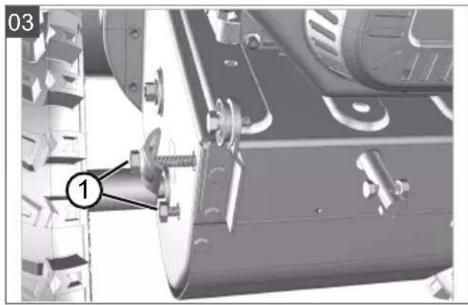
5.1 Fitting the lower brace (03, 04)
Mount the lower brace on the left and right at the bottom of the snow blower.
- Undo the screws (03/1).
- Attach the lower brace (04/1).
- Insert the bolts (04/2) through the lower brace and tighten.
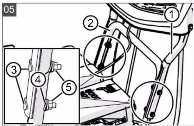
5.2 Fitting the operating panel (05)
- Hold upper brace (05/1) incl. operating panel against lower brace (05/2).
- Insert 2 bolts (05/3) each through upper brace and lower brace and tighten with two washers (05/4) and nuts (05/5).
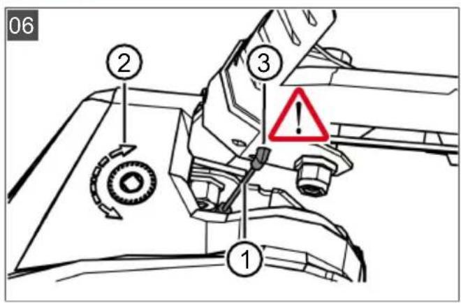
5.3 Installing and adjusting Bowden cables for travel and worm drives (06 - 11)
- Attach the Bowden cable (06/1) for the travel drive (06/2) into the lower hole (06/3) of the right-hand lever.
- Attach the Bowden cable (07/1) for the worm drive (07/2) into the upper hole (07/3) of the left-hand lever.
- Adjust the Bowden cables as follows:
■ Turn the adjuster on the Bowden cable (08/1) in the direction of the arrow (08/a) until the Bowden cable no longer sags (is
slightly tensioned). While turning the adjuster, hold the cable so that it does not become twisted.
■ Tighten lock nut (08/2) (08/b).
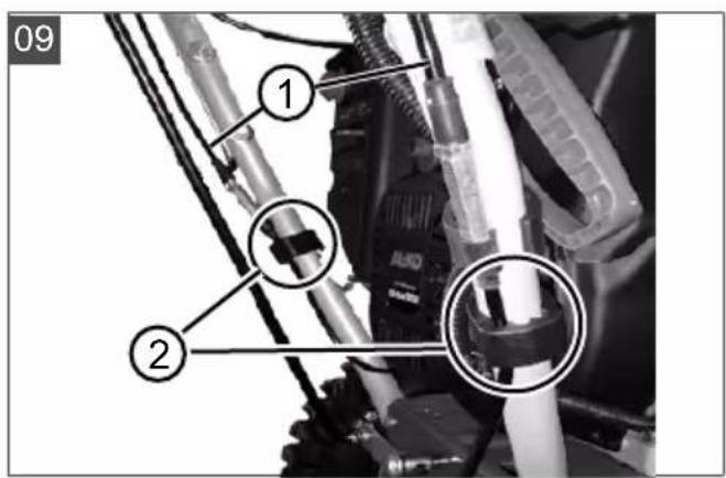
-
Fix the Bowden cables (09/1) with the clamps (09/2) on the left and right of the handlebar.
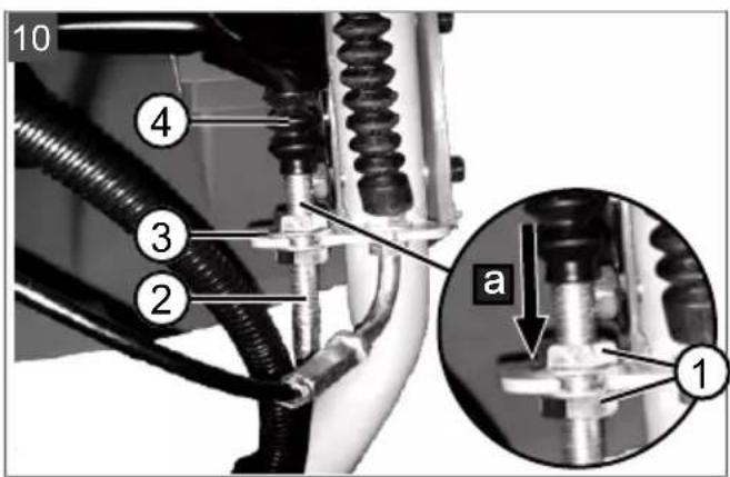
-
Tension the Bowden cable:
■ Loosely tighten the lock nuts (10/1, 11/1).
■ Turn the threaded end piece (10/2, 11/2) upwards until the Bowden cable is tensioned.
■ Turn the lock nuts against the guide (10/3, 11/3) to fix the Bowden cable.
- Pull down the rubber sheath (10/4, 11/4) to the lock nut (10/a, 11/a) to protect the Bowden cable against corrosion.
5.4 Adjusting the Bowden cable (12)
The fine adjustment is carried out via the adjusting screw.
-
Loosen the lock nut (12/2) on the adjusting screw (12/a).
-
Turn the adjusting screw (12/3) (12/b) to lengthen or shorten the path of the Bowden cable. Ensure that the Bowden cable is slightly taut and is not sagging.
-
Re-tighten the lock nut (12/2) (12/a).
5.5 Checking the Bowden cable setting (13)
The Bowden cable of the travel drive lengthens over time. If the travel drive can no longer be switched on while the engine is running, the Bowden cable has become too long and must be tightened.
-
Switch off the appliance (see chapter 6.8 "Stopping the engine (37, 38)", page 39).
-
Re-adjusting the Bowden cable (see chapter 5.3 "Installing and adjusting Bowden cables for travel and worm drives (06 - 11)", page 35).
To check the Bowden cable setting:
-
Start the engine (see chapter 6.7 "Starting the engine (31 - 36)", page 38).
-
Put into gear (see chapter 7.1 "Starting clearing (39 - 41)", page 39).
-
Slowly push the right handle (13/1) downwards (13/a) until a slight resistance is felt. The pressure point of the clutch has been determined.
-
If the travel drive is not switched on: Repeat the previous steps.
-
If adjusting the Bowden cable is not successful: Contact one of the manufacturer's service centres.
5.6 Mounting the rod for the gear selector lever (14, 15)
-
Attach the rod (14/1) at the bottom into the gear shift mount (15/2).
-
Attach the rod on the top of the gear selector lever (15/3) in the mount.
-
Secure the rod at the top and bottom with washers and cotter pins.
5.7 Installing the flexible shaft for the snow discharge spout (16, 17)
- At the snow discharge spout:
■ Insert pin (16/1) of one end of flexible shaft (16/2) into auger (16/3) as far as it will go (16/a).
■ Tighten knurled nut (16/4) by hand.
- Under the operating panel:
- Insert pin of the other end of flexible shaft (17/1) from below into crank (17/2) as far as it will go (17/a).
■ Tighten knurled nut (17/3) by hand.
5.8 Plugging in the heater and lighting plug (18)
-
Connect the plug parts (18/1) for the heater and lighting.
-
Secure the plug connection.
5.9 Fitting the snow discharge spout (19-22)
-
Apply spray oil (or grease) to the sliding surface (19/1) of the snow discharge spout on the snow blower.
-
Fit the snow discharge spout (20/1) (20/a, 21/a).
-
Insert the mounting bolts (21/2) through the brackets and snow discharge spout from the inside.
-
Secure the snow discharge spout with the self-locking nuts (21/3).
-
Insert the mounting bolts (22/1) through the large guide plate (22/2) and fit the small guide plate (22/3).
Note: The small guide plate must lie on top of the large guide plate.
-
Insert the guide plates with the mounting bolts from below into the snow discharge spout.
-
Fit washers (22/4) onto the bolts.
-
Securely tighten the self-locking nuts (22/5).
5.10 Connecting the Bowden cable to the discharge flap (23)
This Bowden cable moves the discharge flap of the snow discharge spout and serves to set the discharge height.
- Hook the Bowden cable into the guides (23/1, 23/2). The rubber sheath must be attached to the outer Bowden cable.
- Tighten lock nuts (23/3, 23/4) firmly against the guide until the Bowden cable is taut.
- Use the lever for setting the discharge height to check the length of the Bowden cable:
■ Move the lever all the way to the front. The discharge flap must move all the way down.
■ Move the lever all the way to the rear. The discharge flap must move all the way up.
If necessary, change the length of the Bowden cable.
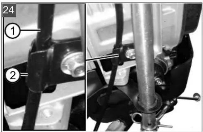
5.11 Attaching the Bowden cable (24)
- Attach the Bowden cable (24/1) into the mount (24/2) under the engine.
6 START-UP
WARNING! Risk of injury from faulty appliance. Operation of an faulty appliance can result in serious injury and damage to the appliance.
- Operate the appliance only when it is undamaged and has not defects, and when no parts are missing or loose.
NOTE Always perform a visual check prior to start-up. Do not operate the equipment if the operating and/or fastening parts are loose, damaged, or worn.
6.1 Operating material
⚠️ DANGER! Risk of explosion and fire. An escaping petrol/air mixture can cause an explosive atmosphere. Deflagation, explosion and fire can lead to serious and even fatal injuries if fuel is not handled properly.
■ Do not smoke when dealing with petrol.
■ Only handle petrol out of doors and never in enclosed spaces.
⚠️ DANGER! Risk of poisoning. The engine exhaust gases contain carbon monoxide that can kill a person within a few minutes.
■ Operate the engine only outdoors, never in a closed room.
■ Do not inhale the engine exhaust gases.
■ Switch off the engine if you feel nauseous, dizzy or weak during use. Immediately consult a doctor.
NOTE Dispose of used engine oil in an environmentally responsible manner! We recommend disposing of waste oil in a closed container at a recycling centre or customer service centre. Do not dispose of waste oil:
In domestic waste
In sewers or drains
In the ground
i NOTE Observe the enclosed operating instructions for the engine!
Before starting operation, the engine must be filled with oil and the snow blower filled with petrol.
For information on petrol and engine oil: see technical data.
6.2 Filling with engine oil (25)
- Unscrew the oil filler cap (25/1) and put it down in a clean place.
- Pour in oil through a funnel.
- Check the fill level with an oil dipstick, see engine operating manual.
- Securely tighten and clean the oil filler neck.
6.3 Filling with petrol (25)
- Unscrew the tank cap (25/2) and put it down in a clean place.
- Pour in petrol through a funnel.
- Securely tighten the fuel filler cap and clean the tank filler neck.
6.4 Checking the tyre pressure (26)
- Check the tyre pressure particularly before using for the first time in the winter and at least every three months during the season. The maximum permissible tyre pressure is indicated on the tyres (26/1).
Note: Note: 1 bar = approx. 14.5 psi
- Pump up both tyres. Both tyres must have the same pressure.
6.5 Adjusting the clearing height (27 - 29)

CAUTION! Risk of injury. Risk of cuts
when reaching into the running transport auger.
■ Adjust the clearing height only with the engine switched off and the transport auger at standstill.
Adjust the clearing height so that no gravel or other foreign matter can be picked up. Give consideration to very uneven ground, for example tyre tracks, and to manhole covers or paving stones.
- Move the appliance to level ground for adjustment.
- Unfasten the clamping screws (27/1) of the skids (27/2) on the left and right of the plough (27/3).
- Push the skids up or down (27/a) to raise the clearing plate (28/1) to the desired height.
- Tighten the clamping screws of the skids.
- Ensure that both skids are at the same height so that the clearing plate runs parallel to the ground (28/a).
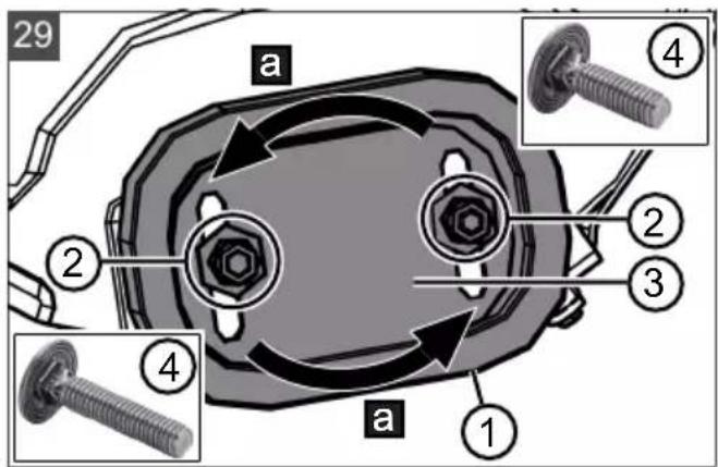
Skids worn (29)
If the wear edge (29/1) of the skids is worn down, turn it 180^ to use the second side.
- Unscrew the nuts (29/2) including the washers.
- Remove the metal plate (29/3).
- Turn the skid by 180^ (29/a).
- Fit washers and tighten nuts.
Note: Be careful not to swap the clamping screws (29/4) because they are of different lengths.
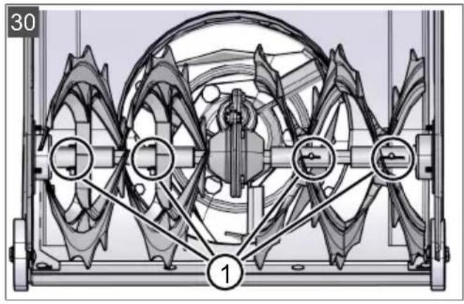
6.6 Checking the shear pins on the appliance (30, 46)

IMPORTANT! Danger of damage to the
appliance. A frozen auger gearbox can result in damage to the V-belt.
-
Check whether the auger gearbox is frozen before starting the engine.
Park the snow blower in a suitable place to allow the auger gearbox to thaw, if necessary. -
Before every start, check that the shear pins (30/1, 46/2) are undamaged.
- Replace broken shear pins with OEM spare parts (see chapter 9.4 "Replacing the shear pins (30, 46)", page 41). Use
of non-approved spare parts can result in serious damage to the appliance!
■ Two spare shear pins (01/8) can be found on the operating panel.
- Inspect all operating elements, safety devices, nuts, bolts and studs of the device for completeness, tightness and sound condition.
6.7 Starting the engine (31 - 36)
The lights switch on automatically when the engine is started and go out when the engine stops.

DANGER! Risk of poisoning. The engine
exhaust gases contain carbon monoxide that can kill a person within a few minutes.
■ Operate the engine only outdoors, never in a closed room.
■ Do not inhale the engine exhaust gases.
■ Switch off the engine if you feel nauseous, dizzy or weak during use. Immediately consult a doctor.

IMPORTANT! Danger of damage to the
appliance. A frozen auger gearbox can result in damage to the V-belt.
- Check whether the auger gearbox is frozen before starting the engine.
- Park the snow blower in a suitable place to allow the auger gearbox to thaw, if necessary.
Starting process (31 - 34)
- Check the oil and fuel level.
- Open fuel cock (31/1) (31/a).
- Check that travel drive and auger drive are disengaged. Both clutch levers must be in the upright position.
- Move choke (31/2) to the "CLOSED" position (31/b).
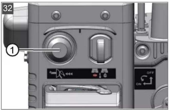
- Press primer button (32/1) 3x at intervals of approx. 2 seconds. At temperatures below 10^ C, press the primer button 5x.
- Move throttle lever (33/1) to the Fast position (hare) (33/a).
- Insert engine key (34/1).
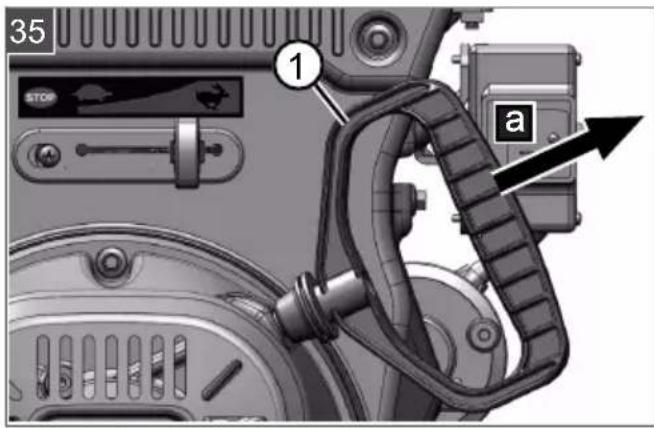
Manual start (35)
- Pull the starter cable (35/1) out slightly (35/a) until initial resistance is felt, then pull out sharply and allow it to wind back in slowly.
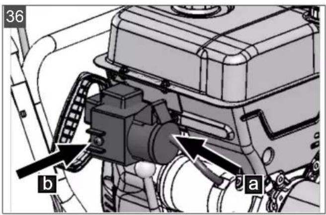
230 V starting process (36)
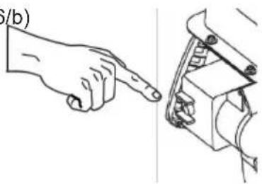
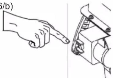
- (36/a)

natural_image
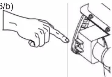
Pure electrical connector diagrams without any text or symbols- (36/b)
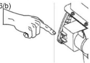
natural_image
Line drawing of a hand pointing at a mechanical component (no text or symbols)6.8 Stopping the engine (37, 38)
WARNING! Danger from rotating appliance parts! Reaching into rotating appliance parts will result in serious injuries!
■ Never reach into the rotating transport auger!
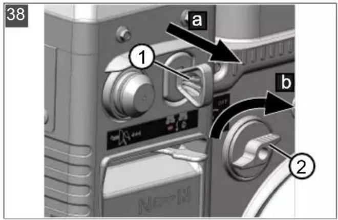
- Move the throttle lever (37/1) to the "Slow" position (Tortoise) (37/a).
- To prevent freezing, allow transport auger and discharge wheel to continue to run until they are more or less free of snow. The V-belts could otherwise be damaged during starting.
- Remove engine key (38/1) (38/a).
- The engine stops.
- Turn fuel cock (38/2) to the "OFF" (closed) position (38/b).
7 OPERATION
7.1 Starting clearing (39 - 41)
WARNING! Danger from rotating appliance parts! Reaching into rotating appliance parts will result in serious injuries!
■ Never reach into the rotating transport auger!
WARNING! Objects being discharged!
Risk of injury and risk of material damage due to objects being discharged!
■ Never turn the discharge channel in the direction of persons, animals, windows, cars or doors.
-
Start clearing.
-
Check the position of the snow discharge spout and adjust the discharge direction using the hand crank (39/1).
- Adjust the discharge height (39/2).
- Start the engine (see chapter 6.7 "Starting the engine (31 - 36)", page 38).
- Engage the gear for the travel drive (40/3):
■ 1 to 6 are forward gears, with 1 the lowest and 6 the highest gear.
■ R1 and R2 are reverse gears, with R1 the lower and R2 the higher gear.
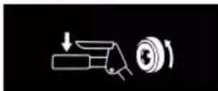
- Push clutch lever (40/4) for the auger drive (40/a).
- Push clutch lever (41/5) for the travel drive (41/a).
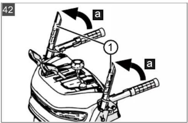
7.2 Stopping clearing (42)
- Release the clutch lever (42/1) to disengage the auger drive and travel drive (42/a).
To prevent freezing, allow transport auger and discharge wheel to continue to run until they are more or less free of snow. A frozen transport auger would damage the V-belts.
The snow blower comes to a standstill, transport auger and discharge wheel stop.
7.3 Changing gear for the travel drive (41 - 43)
IMPORTANT! Risk of damage to the appliance. The transmission is damaged if the clutch is not disengaged before the gear change.
■ First disengage the clutch, then change gears.
-
Release clutch lever for the travel drive (42/1), i.e. disengage (42/a). Note: The transport auger blocks when it is stopped in wet and heavy snow and then re-started. Do not release the clutch lever for the auger drive!
-
Change gear with gear lever (43/1).
- Push clutch lever (41/5) for the travel drive (41/a).
7.4 Clearing clogging in the snow discharge spout (42, 44)
NOTE Allow the transport auger to run at all times, if possible, in order to avoid clogging in heavy and wet snow.
If the snow is no longer discharged correctly, snow and ice deposits on the transport augers and in the discharge channel may be the cause.
- Release the clutch lever (42/1) to disengage the auger drive and travel drive (42/a).
- Switch off the engine (see chapter 6.8 "Stopping the engine (37, 38)", page 39).
- Carefully clear the snow from the discharge channel and transport auger using the cleaning tool (44/1).
If the snow discharge is still unsatisfactory, take the appliance to a specialist workshop.
8 REPAIR
WARNING! Risk of injury during repair work. Improper repairs can lead to serious injuries and damage to the appliance.
- Have repair work performed by the manufacturer's service centres and authorised specialist companies only!
A professional inspection is always required:
■ After colliding with an obstacle.
■ If the engine stops suddenly.
If the transport auger or discharge wheel are damaged.
9 MAINTENANCE AND CARE
CAUTION! Risk of injury. Sharp-edged and moving appliance parts can lead to injury.
■ Always wear protective gloves during maintenance, care and cleaning work!
■ Switch off the engine and check that the engine is at a standstill!
■ Remove the spark plug connector!
■ Clean the appliance after every use. In particular, remove any residues of road salt.
- Do not spray the appliance with water. Penetrating water can lead to malfunctions (ignition system, carburettor).
■ Always replace a defective silencer.
- Observe the maintenance schedule.
- Observe the engine operating manual.
9.1 Maintenance schedule
Before every use
- Check the oil level (see engine operating manual).
- Check the shear pins.
- Inspect the appliance for damage.
- Check whether the transport auger is frozen.
After the first 5 operating hours
■ Change the engine oil (see engine operating manual).
Every 8 operating hours
■ Grease the transport auger.
Every 3 months
- Check the tyre pressure.
■ Oil the ring of the snow discharge spout with spray oil.
Once a year
- Replace the spark plug (see engine operating manual).
■ Grease the transport auger.
■ Change the engine oil.
9.2 Greasing the transport auger (45)
Pump approx. 2-3 strokes of multi-purpose grease into grease nipple (45/1) using a grease gun.
9.3 Servicing the travel and auger drives (08)
WARNING! Risk of injury during maintenance work. Improper maintenance can result in serious injury and in damage to the appliance.
■ Adjust the Bowden cable only with the engine switched off.
- Stop the engine if the travel/auger drive cannot be switched off.
■ Do not try to carry out repairs yourself and contact a specialist workshop immediately.
NOTE Moisture in the Bowden cable can result in corrosion or freezing. A damaged Bowden cable must be replaced.
Adjust Bowden cable
If the travel/auger drive cannot be engaged with the engine running, the respective Bowden cable must be adjusted.
- Loosen lock nut (08/2).
- Turn the adjuster on the Bowden cable (08/1) in the direction of the arrow (08/a) until the Bowden cable no longer sags (is slightly tensioned). While turning the adjuster, hold the cable so that it does not become twisted.
- Tighten lock nut (08/2) (08/b).
-
To check the setting, start the engine and switch on the travel/auger drive.
-
If the travel/auger drive still cannot be properly engaged, the appliance must be taken to a specialist workshop.
9.4 Replacing the shear pins (30, 46)
For the safety of the operator and appliance, the shear pins (30/1) can break after a blockage of the transport auger.
NOTE Replace broken shear pins with OEM spare parts. Use of non-approved spare parts can result in serious damage to the appliance!
- Switch off the appliance and remove the spark plug connector.
- Remove the cotter pin (46/1) (46/a).
- Pull out the damaged shear pins (46/2) (46/b).
- Inspect the shaft for damage.
- Insert a new shear pin and secure with cotter pin.
10 HELP IN CASE OF MALFUNCTIONS
CAUTION! Risk of injury. Sharp-edged and moving appliance parts can lead to injury.
■ Always wear protective gloves during maintenance, care and cleaning work!
■ Switch off the engine and check that the engine is at a standstill!
■ Remove the spark plug connector!
NOTE For malfunctions that are not listed in this table or that you cannot resolve yourself, please contact our customer service.
| Malfunction Remedy | |
| Engine does not start. | Fill with petrol. |
| Move the throttle lever to the “Start” position. | |
| Switch on the choke and press the primer button. | |
| Service the spark plug. | |
| Engine loses power. | Clean the discharge channel/housing. |
| Clear snow and ice from the transport auger and discharge wheel. | |
| Reduce the working speed. | |
| Malfunction Remedy | |
| Travel drive does not function with clutch lever pressed. | Adjust the Bowden cable. |
| Take the appliance to a Customer Service Centre. | |
| Travel drive cannot be stopped (does not disengage). | Switch off the engine.Do not try to repair the appliance yourself!Take the appliance to a Customer Service Centre. |
| Transport auger does not rotate with clutch lever pressed. | Shear ping broken; replace the shear pin. |
| Adjust the Bowden cable. | |
| Take the appliance to a Customer Service Centre. | |
| Transport auger cannot be stopped (does not disengage). | Switch off the engine.Do not try to repair the appliance yourself!Take the appliance to a Customer Service Centre. |
| Abnormal appliance vibrations. | Inspect transport auger and discharge wheel. |
| Appliance pulls to one side. | Check tyre pressure and correct, if necessary. |
| Check the skids and adjust or replace, as necessary. | |
Replacement parts
See: www.al-ko.com
11 STORAGE
WARNING! Danger of explosion and fire. Petrol vapours are highly inflammable.
- Do not store the appliance close to naked flames or sources of heat.
Thoroughly clean the appliance after each use and – if present – attach all covers. Store the appliance in a dry, lockable place out of the reach of children.
If the appliance is to be stored for a prolonged period, such as after the winter, the following operations are necessary to prevent damage:
Draining the carburettor:
■ Start the engine.
- Close the fuel cock.
- Wait until the engine stops.
- Allow the engine to cool down.
■ Store the appliance in a dry place out of the reach of children and unauthorised persons.
■ Empty the fuel tank or fill it completely.
■ Remove the engine key.
■ Remove the spark plug connector.
12 DISPOSAL
Petrol and motor oil do not belong in household waste or the public sewer system, but should be collected and disposed of separately.
■ Before disposing of the device you must empty the fuel tank and the engine oil tank!
Packaging, equipment and accessories are made from recyclable materials, and must be disposed of accordingly.
13 AFTER-SALES/SERVICE
In the event of questions of warranty, repair or spare parts, please contact your nearest AL-KO Service Centre. These can be found on the Internet at:
www.alko-garden.com/service-contacts
Further information on spare parts can be found at:
www.alko-garden.com/spareparts
14 INFORMATION ON THE DECLARATION OF CONFORMITY
We hereby declare, as the exclusively responsible party, that this product in its marketed form
meets the requirements of the harmonised EU Directives, EU safety standards and the product-specific standards. The Declaration of Conformity forms part of the operating instructions and is included with the machine.
15 GUARANTEE
We will resolve any material or manufacturing faults on the appliance during the legal warranty period for claims relating to faults, in accordance with our choice either to repair or replace. The legal warranty period is determined by the legislation of the country in which the appliance was purchased.
Our warranty promise applies only if:
These operating instructions are heeded
■ The appliance is handled correctly
■ Original spare parts have been used
The warranty becomes void in the case of:
■ Unauthorised repair attempts
■ Unauthorised technical modifications
Non-intended use
The guarantee excludes:
■ Paint damage that can be attributed to normal wear and tear
■ Wear parts that are marked with a frame xxxxxx (x) on the spare parts card
■ Internal combustion engines (these are covered by the guarantee provisions of the corresponding engine manufacturers)
The guarantee period commences with purchase by the first end user. The date on the proof of purchase is decisive. In the event of a guarantee claim, please take this guarantee declaration and the original proof of purchase, and contact your dealer or the nearest authorised customer service centre. This statement does not affect the purchaser's statutory claims for defects against the vendor.
TRADUCTION DE LA NOTICE D'UTILISATION ORIGINALE
Table des matières
natural_image
Simple line drawing of a hand holding a device with a circular button, no text or symbols present
natural_image
Diagram of a pipe valve mechanism with directional arrows indicating flow or movement (no text or symbols)natural_image
Diagram showing three curved pipe fittings with directional arrows indicating movement or flow (no text or symbols)natural_image
Pure electrical connector diagrams without any text or symbols- (36/b)

natural_image
Illustration of a hand pointing at a mechanical component (no text or symbols)natural_image
Diagram of a mechanical device with directional arrows indicating motion or force (no text or symbols)flowchart
graph TD
    A["Top Pipe"] --> B["Downward Arrow"]
    C["Left Pipe"] --> D["Upward Arrow"]
    E["Right Pipe"] --> F["Downward Arrow"]
    G["Bottom Pipe"] --> H["Upward Arrow"]
    I["Left Pipe"] --> J["Downward Arrow"]
    K["Right Pipe"] --> L["Upward Arrow"]
natural_image
Diagram showing two types of electronic components: a cylindrical device with a lens and a plug, and a separate plug with an arrow indicating direction (no text or symbols present)- (36/b)

natural_image
Illustration of a hand pointing at a mechanical component (no text or symbols)
natural_image
Two electronic component diagrams with arrows indicating direction (no text or symbols)- (36/b)

natural_image
Line drawing of a hand pointing at a mechanical component (no text or symbols)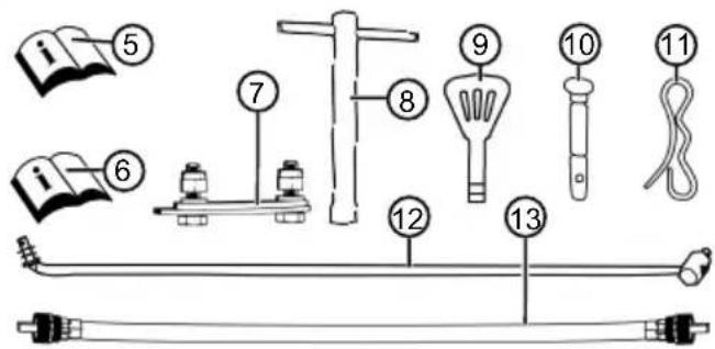
natural_image
Diagram showing two types of electrical connectors: a cylindrical device with a lens and a plug, and a separate plug with a black arrow indicating direction (no text or symbols present)- (36/b)
natural_image
Illustration of a hand pointing at a mechanical component (no text or symbols)6.8 Zaustavljanje motora (37, 38)
natural_image
Two abstract line drawings: one with a downward arrow and the other with a wavy line (no text or symbols)
Символ Значење
Возни погон
Покретање/
Заустављање

natural_image
Simple line drawing of a hand holding a device with a circular button, no text or symbols present
Поравнајте
natural_image
Diagram showing a pipe valve mechanism with directional arrows and a separate electrical component (no text or symbols)Подесити висину
natural_image
Diagram showing three curved pipe fittings with directional arrows indicating flow or movement (no text or symbols)2.6 Преглед производа (01)
natural_image
Diagram showing two types of electronic components: a cylindrical device with a handle and a plug with wires, plus an upward arrow (no text or symbols)
natural_image
Two abstract line drawings: a hand holding a rectangular object and a wavy line with a hook, both on black background (no text or symbols)
Symbol Znaczenie
natural_image
Simple line drawing of a hand holding a device with a circular button, no text or symbols present
natural_image
Diagram of a pipe valve mechanism with directional arrows indicating flow or movement (no text or symbols)flowchart
graph TD
    A["Conical Pipe"] --> B["Curved Pipe"]
    B --> C["Left Side Flow"]
    C --> D["Right Side Flow"]
    D --> E["Downward Flow"]
natural_image
Technical line drawing of two electronic components with an arrow indicating direction (no text or symbols)- (36/b)

natural_image
Illustration of a hand pointing to a mechanical component (no text or symbols present)
natural_image
Diagram of a mechanical device with directional arrows indicating motion or force (no text or symbols)flowchart
graph TD
    A["Conical Pipe"] --> B["Curved Pipe"]
    B --> C["Left Side Flow"]
    C --> D["Right Side Flow"]
    D --> E["Downward Flow"]
2.6 Prehl'ad výrobku (01)
natural_image
Pure electrical connector diagrams without any text or symbols- (36/b)

natural_image
Line drawing of a hand pointing at a mechanical component (no text or symbols)6.8 Odstavenie motora (37, 38)

natural_image
Two abstract line drawings: one with a downward arrow and the other with a wavy line (no text or symbols)

natural_image
Simple line drawing of a hand holding a device with a circular button, no text or symbols present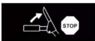
Szimbólum Jelentés
natural_image
Diagram of a mechanical device with directional arrows indicating motion or force (no text or symbols)
natural_image
Diagram showing three curved pipe fittings with directional arrows indicating movement or flow (no text or symbols)4 A GÉP KICSOMAGOLÁSA (02)
natural_image
Pure electrical connector diagrams without any text or symbols- (36/b)

natural_image
Line drawing of a hand pointing at a mechanical component (no text or symbols)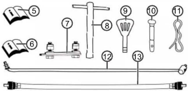
■ Før alle former for indstilling
natural_image
Pure electrical connector diagrams without any text or symbols- (36/b)
natural_image
Illustration of a hand pointing at a mechanical component (no text or symbols)natural_image
Diagram showing two types of electrical connectors: a cylindrical device with a handle and a plug, and a separate plug with a black arrow pointing upward (no text or symbols)- (36/b)

natural_image
Illustration of a hand pointing at a mechanical component (no text or symbols)■ Unngå at maskinen velter!
natural_image
Pure electrical connector diagrams without any text or symbols- (36/b)

natural_image
Illustration of a hand pointing at a mechanical component (no text or symbols)6.8 Stoppe motor (37, 38)
9 VEDLIKEHOLD OG PLEIE
natural_image
Diagram showing two types of electronic components: a cylindrical device with lens and a plug, and a separate plug with an arrow indicating direction (no text or symbols)- (36/b)

natural_image
Illustration of a hand pointing to a mechanical clamp or bracket (no text or symbols present)natural_image
Diagram showing two types of electrical connectors: a cylindrical device with a lens and a plug, and a separate plug with a black arrow pointing upward (no text or symbols)- (36/b)

natural_image
Illustration of a hand pointing at a mechanical component (no text or symbols)6.8 Mootori seiskamine (37, 38)

natural_image
Two abstract line drawings: one with a downward arrow and the other with a wavy line (no text or symbols)
natural_image
Diagram of a mechanical device with directional arrows indicating motion or force (no text or symbols)natural_image
Diagram showing three curved pipe fittings with directional arrows indicating movement or flow (no text or symbols)2.6 Gaminio apžvalga (01)
natural_image
Two technical diagrams showing a connector and a directional arrow (no text or symbols)
6.8 Variklio sustabdymas (37, 38)
natural_image
Diagram of a mechanical device with directional arrows indicating motion or force (no text or symbols)flowchart
graph TD
    A["Conical Pipe"] --> B["Curved Pipe"]
    B --> C["Left Side Flow"]
    B --> D["Right Side Flow"]
natural_image
Diagram showing two types of electronic components: a cylindrical device with a handle and a plug, and a separate plug with a black arrow pointing upward (no text or symbols)
natural_image
Two abstract line drawings: one with a downward arrow and the other with a wavy line (no text or symbols)


natural_image
Simple line drawing of a hand holding a camera lens and pointing downward (no text or symbols)
Simbol Semnificatie
natural_image
Diagram of a mechanical device with directional arrows indicating motion or force (no text or symbols)
natural_image
Diagram showing three curved pipe fittings with directional arrows indicating movement or flow (no text or symbols)natural_image
Two technical diagrams showing a mechanical component and a connector with an arrow indicating direction (no text or symbols present)- (36/b)

natural_image
Illustration of a hand pointing at a mechanical component (no text or symbols)natural_image
Two abstract line drawings: one with a downward arrow and the other with a wavy line (no text or symbols)
natural_image
Simple line drawing of a hand holding a device with a circular button, no text or symbols present
natural_image
Diagram of a mechanical device with curved arrows indicating motion or force direction (no text or symbols)natural_image
Diagram showing three curved pipe fittings with directional arrows indicating movement or flow (no text or symbols)2.6 Преглед на продукта (01)
natural_image
Diagram showing two types of connectors: a mechanical device and a cable with an arrow indicating direction (no text or symbols)- (36/b)

natural_image
Illustration of a hand pointing at a mechanical component (no text or symbols present)natural_image
Two abstract line drawings: one with a downward arrow and the other with a wavy line (no text or symbols)
natural_image
Simple line drawing of a hand holding a device with a circular button, no text or symbols present
natural_image
Diagram of a mechanical device with directional arrows indicating motion or force (no text or symbols)flowchart
graph TD
    A["Conical Pipe"] --> B["Flow Up"]
    A --> C["Flow Down"]
    D["T bent Pipe"] --> E["Flow Up"]
    D --> F["Flow Down"]
    G["T bent Pipe"] --> H["Flow Up"]
    G --> I["Flow Down"]
natural_image
Technical illustration of two electronic components with an arrow indicating direction (no text or symbols)- (36/b)
natural_image
Illustration of a hand pointing to a mechanical component, with no visible text or symbolsnatural_image
Diagram of a mechanical device with directional arrows indicating motion or force (no text or symbols)natural_image
Diagram showing fluid flow around a nozzle with directional arrows indicating movement (no text or labels)natural_image
Pure electrical connector diagrams without any text or symbols- (36/b)

natural_image
Illustration of a hand pointing at a mechanical component (no text or symbols)Imported by: AL-KO Gardentech UK Ltd, Murray way, Wincanton, Somerset, BA9 9RS / UK | +44 (0) 1963 828055 shop.uk@al-ko.com | www.alko-garden.uk
AL-KO Service: www.al-ko.com/service-contacts



- Inhaltsverzeichnis
- SnowLine 620.4 E III LED
- Motor stoppen (37, 38)
- ABOUT THESE OPERATING INSTRUCTIONS
- Symbols on the title page
- Symbol Meaning
- Legends and signal words
- PRODUCT DESCRIPTION
- Designated use
- Possible foreseeable misuse
- Safety and protective devices
- Clutch lever
- Adjustable snow discharge spout
- Scope of supply
- Symbols on the appliance
- Safety signs
- Operating signs
- Product overview (01)
- No. Component
- SAFETY INSTRUCTIONS
- WARNING! Danger of explosion and fire.
- Safety instructions in accordance with ISO 8437, Annex A
- Getting to know the appliance
- Preparation
- Operation
- Maintenance and storage
- WARNING! Serious hand injuries when cleaning the blocked discharge channel!
- Safety instructions relating to operation
- Handling of petrol and oil
- UNPACKING APPLIANCE (02)
- ASSEMBLY
- Necessary tools
- Fitting the lower brace (03, 04)
- Fitting the operating panel (05)
- Installing and adjusting Bowden cables for travel and worm drives (06 - 11)
- Adjusting the Bowden cable (12)
- Checking the Bowden cable setting (13)
- Mounting the rod for the gear selector lever (14, 15)
- Installing the flexible shaft for the snow discharge spout (16, 17)
- Plugging in the heater and lighting plug (18)
- Fitting the snow discharge spout (19-22)
- Connecting the Bowden cable to the discharge flap (23)
- Attaching the Bowden cable (24)
- START-UP
- Operating material
- Filling with engine oil (25)
- Filling with petrol (25)
- Checking the tyre pressure (26)
- Adjusting the clearing height (27 - 29)
- CAUTION! Risk of injury. Risk of cuts
- Skids worn (29)
- Checking the shear pins on the appliance (30, 46)
- IMPORTANT! Danger of damage to the
- Starting the engine (31 - 36)
- DANGER! Risk of poisoning. The engine
- Starting process (31 - 34)
- Manual start (35)
- V starting process (36)
- Stopping the engine (37, 38)
- OPERATION
- Starting clearing (39 - 41)
- Stopping clearing (42)
- Changing gear for the travel drive (41 - 43)
- Clearing clogging in the snow discharge spout (42, 44)
- REPAIR
- MAINTENANCE AND CARE
- Maintenance schedule
- Before every use
- After the first 5 operating hours
- Every 8 operating hours
- Every 3 months
- Once a year
- Greasing the transport auger (45)
- Servicing the travel and auger drives (08)
- Adjust Bowden cable
- Replacing the shear pins (30, 46)
- HELP IN CASE OF MALFUNCTIONS
- STORAGE
- DISPOSAL
- AFTER-SALES/SERVICE
- INFORMATION ON THE DECLARATION OF CONFORMITY
- GUARANTEE
- TRADUCTION DE LA NOTICE D'UTILISATION ORIGINALE
- Table des matières
- Zaustavljanje motora (37, 38)
- Символ Значење
- Преглед производа (01)
- Symbol Znaczenie
- Prehl'ad výrobku (01)
- Odstavenie motora (37, 38)
- A GÉP KICSOMAGOLÁSA (02)
- Stoppe motor (37, 38)
- VEDLIKEHOLD OG PLEIE
- Mootori seiskamine (37, 38)
- Gaminio apžvalga (01)
- Variklio sustabdymas (37, 38)
- Преглед на продукта (01)
Brand : AL-KO
Model : SnowLine 620.4 E III LED
Category : Snow blower