
CSE 55 T - Saw Flex - Free user manual and instructions
Find the device manual for free CSE 55 T Flex in PDF.
| Product type | Plunge circular saw |
| Brand | Flex |
| Model | CSE 55 T |
| Mains voltage | 230 V / 50 Hz |
| Protection class | II (double insulation) |
| Power consumption | 1350 W |
| No-load speed | 2600 – 5200 rpm |
| Cutting speed | 22 – 44 m/s |
| Blade bore | 20 mm |
| Blade diameter (max/min) | 160 / 149 mm |
| Cutting width max. | 1.8 mm |
| Cutting height | 0 – 55 mm |
| Cutting depth with guide rail | 0 – 49 mm |
| Bevel range | -1° to 48° |
| Weight (without cable) | 4.0 kg |
| Power cable length | 5.0 m |
| Sound pressure level | 92 dB(A) |
| Sound power level | 103 dB(A) |
| Vibration (emission value) | < 2.5 m/s² |
| Dust extraction connection | Universal adapter Ø 32 mm |
| Speed adjustment | Continuous (6 positions, 2600–5200 rpm) |
| Main functions | Plunge cuts, ripping, cross cuts, miter cuts; depth and angle adjustment; use on guide rail |
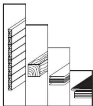
| Compatible materials | Solid wood, chipboard and MDF, fiber cement (diamond blade) |
| Max. cutting thickness | 55 mm (wood) |
| Maintenance | Regular cleaning with compressed air; occasional lubrication of joints; repairs by authorized service center |
| Manufacturer warranty | 2 years |
| Compliance standards | CE, EN 60745, directives 2004/108/EC, 2006/42/EC, 2011/65/EU |
Frequently Asked Questions - CSE 55 T Flex
User questions about CSE 55 T Flex
0 question about this device. Answer the ones you know or ask your own.
Ask a new question about this device
Download the instructions for your Saw in PDF format for free! Find your manual CSE 55 T - Flex and take your electronic device back in hand. On this page are published all the documents necessary for the use of your device. CSE 55 T by Flex.
USER MANUAL CSE 55 T Flex
Manager Research & Development (R & D)
09.07.2012
Manager Quality Department (QD)
Garantie
Symbols used in this manual 17
Important safety information 17
Noise and vibration 20
Overview 21
Technical specifications 22
Instructions for use 23
Maintenance and care 29
Disposal information 30
-Declaration of Conformity 30
Guarantee 30
Symbols used in this manual

WARNING!
Denotes impending danger.
Non-observance of this warning may result in death or extremely severe injuries.

CAUTION!
Denotes a possibly dangerous situation.
Non-observation of this warning may result insight injury or damage to property.

NOTE
Denotes application tips and important information.
Symbols on the power tool

Before switching on the power tool, read the operating manual!
Wear goggles!

Wear ear protection!

Disposal information for the old machine (see page 30)!
For your safety

WARNING!
Before using the power tool, please read andfollow:
-these operating instructions,
-the "General safety instructions" on the handling of power tools in the enclosed booklet (leaflet-no.: 315.915),
-the currently valid site rules and the regulations for the prevention of accidents.
This power tool is state of the art and has been constructed in accordance with the acknowledged safety regulations.
Nevertheless, when in use, the power tool may be a danger to life and limb of the user or a third party, or the power tool or other property may be damaged.
The power tool may be operated only if it is
- a s – i n t e n d e d ,
-in perfect working order.
Faults which impair safety must be repaired immediately.
Intended use
The plunge saw CSE 55 T is designed
- for commercial use in industry and trade,
- for lengthwise and cross cuts with a straight cutting path,
- for cutting solid wood and board materials such as chipboard and wood-core plywood and MDF boards up to a maximum thickness of 55mm
- for cutting fibre cement boards when using a diamond saw blade,
- for use with circular saw blades which FLEX offers for this machine.
Not permitted are
- the use of HSS saw blades and cutting-off wheels,
stationary use as a circular bench saw,
- use outdoors in the rain,
- use in potentially explosive areas.
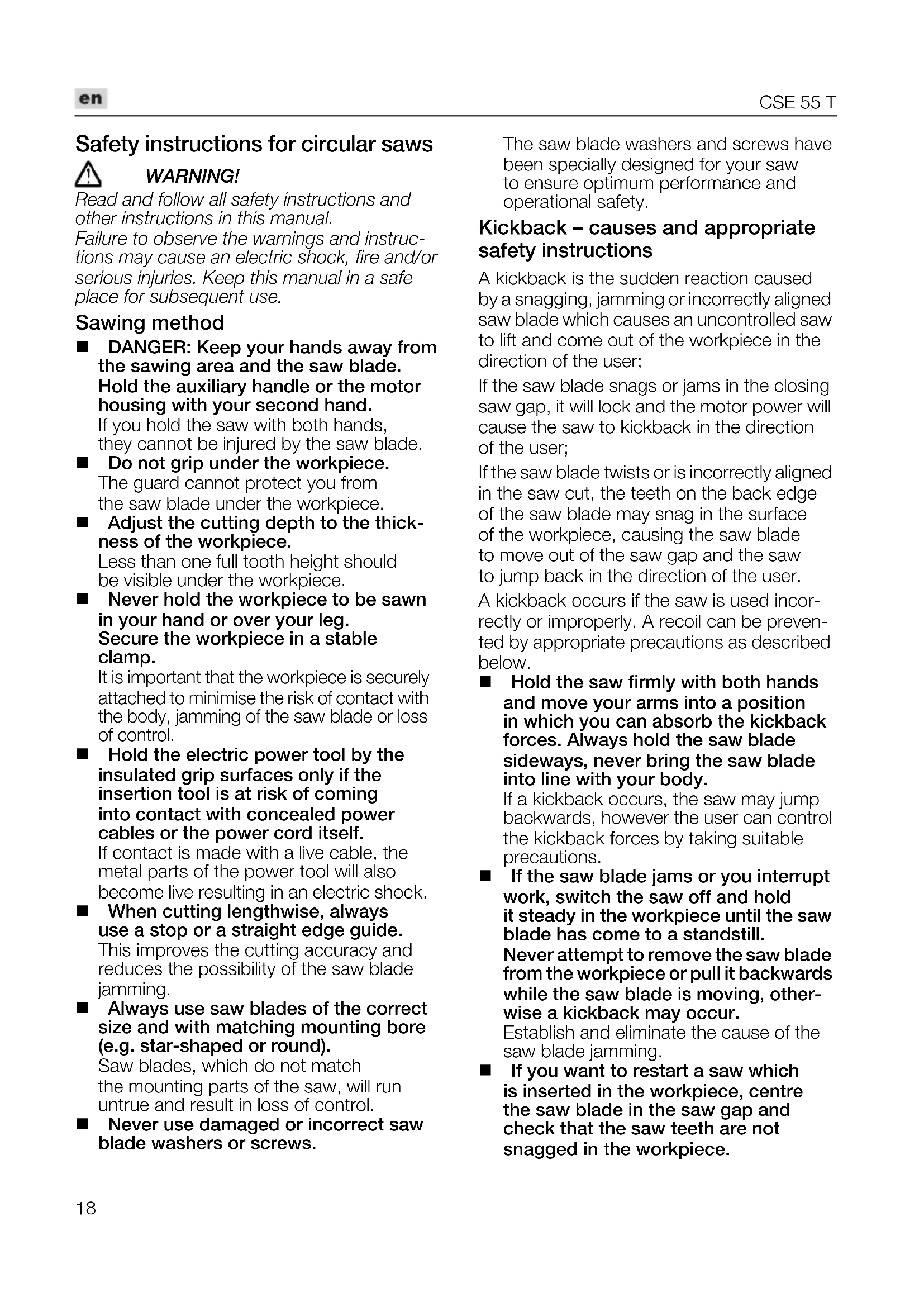
Safety instructions for circular saws

WARNING!
Read and follow all safety instructions and other instructions in this manual.
Failure to observe the warnings and instructions may cause an electric shock, fire and/or serious injuries. Keep this manual in a safe place for subsequent use.
Sawing method
DANGER: Keep your hands away from the sawing area and the saw blade. Hold the auxiliary handle or the motor housing with your second hand. If you hold the saw with both hands, they cannot be injured by the saw blade.
Do not grip under the workpiece. The guard cannot protect you from the saw blade under the workpiece.
Adjust the cutting depth to the thickness of the workpiece. Less than one full tooth height should be visible under the workpiece.
- Never hold the workpiece to be sawn in your hand or over your leg. Secure the workpiece in a stable clamp.
- It is important that the workpiece is securely attached to minimise the risk of contact with the body, jamming of the saw blade or loss of control.
Hold the electric power tool by the insulated grip surfaces only if the insertion tool is at risk of coming into contact with concealed power cables or the power cord itself. If contact is made with a live cable, the metal parts of the power tool will also become live resulting in an electric shock.
- When cutting lengthwise, always use a stop or a straight edge guide. This improves the cutting accuracy and reduces the possibility of the saw blade jamming.
Always use saw blades of the correct size and with matching mounting bore (e.g. star-shaped or round). Saw blades, which do not match the mounting parts of the saw, will run untrue and result in loss of control.
Never use damaged or incorrect saw blade washers or screws.
The saw blade washers and screws have been specially designed for your saw to ensure optimum performance and operational safety.
Kickback - causes and appropriate safety instructions
A kickback is the sudden reaction caused by a snagging, jamming or incorrectly aligned saw blade which causes an uncontrolled saw to lift and come out of the workpiece in the direction of the user;
If the saw blade snags or jams in the closing saw gap, it will lock and the motor power will cause the saw to kickback in the direction of the user;
If the saw blade twists or is incorrectly aligned in the saw cut, the teeth on the back edge of the saw blade may snag in the surface of the workpiece, causing the saw blade to move out of the saw gap and the saw to jump back in the direction of the user.
A kickback occurs if the saw is used incorrectly or improperly. A recoil can be prevented by appropriate precautions as described below.
Hold the saw firmly with both hands and move your arms into a position in which you can absorb the kickback forces. Always hold the saw blade sideways, never bring the saw blade into line with your body.
If a kickback occurs, the saw may jump backwards, however the user can control the kickback forces by taking suitable precautions.
If the saw blade jams or you interrupt work, switch the saw off and hold it steady in the workpiece until the saw blade has come to a standstill. Never attempt to remove the saw blade from the workpiece or pull it backwards while the saw blade is moving, otherwise a kickback may occur.
Establish and eliminate the cause of the saw blade jamming.
If you want to restart a saw which is inserted in the workpiece, centre the saw blade in the saw gap and check that the saw teeth are not snagged in the workpiece.
If the saw blade jams, it may move out of the workpiece or cause a kickback when the saw is restarted.
Support large boards to prevent the risk of a kickback due to a saw blade jamming.
Large boards may sag under their own weight. Boards must be supported on both sides, both near the saw gap and on the edge.
- Do not use blunt or damaged saw blades.
If saw blades are blunt or have incorrectly aligned teeth, the saw gap will be too narrow, causing increased friction, the saw blade to jam and a kickback.
Before sawing, tighten the cutting depth and cutting angle settings.
If you change the settings during sawing, the saw blade may jam and cause a kickback.
- Be particularly careful when sawing in existing walls or other secluded areas.
When sawing, the plunging saw blade may lock in concealed objects and cause a kickback.
Function of the guard
Before use, always check that the guard closes properly. Do not use the saw if the guard does not move freely and does not close immediately. Never clamp or tie the guard, as the saw blade would be unprotected.
If the saw accidentally falls on the floor, the guard may be twisted.
Ensure that the guard moves freely and touches neither the saw blade nor other parts at any cutting angle and depth.
Check the condition and function of the guard spring. If the guard and spring do not function perfectly, have the saw serviced before using it.
Damaged parts, sticky deposits or accumulation of swarf will delay the function of the lower guard.
- When making "plunge cuts", which is not implemented at right angles, ensure that the saw base plate does not move sideways.
A sideways movement may cause the saw blade to jam resulting in a kickback.
- Do not place the saw on the workbench or the floor without putting the guard on the saw blade.
An unprotected coasting saw blade will move the saw against the cutting direction and will saw whatever is in its path.
In doing so, observe the stopping time of the saw.
Function of the riving knife
Use the saw blade which is suitable for the riving knife.
To ensure that the riving knife functions, the body of the saw blade must be thinner than the riving knife and the tooth width must be thicker than the riving knife.
Adjust the riving knife as described in these operating instructions.
Incorrect strength, position and alignment may be the reason that the riving knife does not effectively prevent a kickback.
To ensure that the riving knife can function, it must be situated in the saw gap.
Over short sections the riving knife is ineffective at preventing a kickback.
- Do not operate the saw if the riving knife is twisted.
Even a minor fault can slow down the closure of the guard.
Additional safety instructions
- Do not place hands in the swarf ejector. You may be injured by the rotating parts.
Do not work with the saw above your head.
You do not have adequate control over the electric power tool.
- Do not operate the electric power tool stationary.
It is not designed to be operated with a saw bench.
- Do not use saw blades made of HSS steel.
These types of saw blades can break easily.
Do not saw any ferrous metals.
Glowing swarf may ignite the dust extraction.
The mains voltage and the voltage specifications on the rating plate must correspond.
Noise and vibration
The noise and vibration values have been determined in accordance with EN 60745. The A evaluated noise level of the power tool is typically:
- Sound pressure level: 92 dB(A);
Sound power level: 103 dB(A);
Uncertainty: K = 3 dB.
Total vibration value:
Emission value: a h < 2.5m / s^2
Uncertainty: K = 1.5 m/s

CAUTION!
The indicated measurements refer to new power tools. Daily use causes the noise and vibration values to change.

NOTE
The vibration emission level given in this information sheet has been measured in accordance with a standardised test given in EN 60745 and may be used to compare one tool with another. It may be used for a preliminary assessment of exposure. The declared vibration emission level represents the main applications of the tool. However if the tool is used for different applications, with different accessories or poorly maintained, the vibration emission may differ. This may significantly increase the exposure level over the total working period. However if the tool is used for different applications, with different accessories or poorly maintained, the vibration emission may differ. This may significantly decrease the exposure level over the total working period. Identify additional safety measures to protect the operator from the effects of vibration such as: maintain the tool and the accessories, keep the hands warm, organisation of work patterns.

CAUTION!
Wear ear protection at a sound pressure above 85 dB(A).
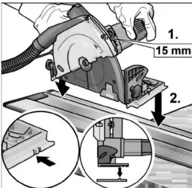
Overview
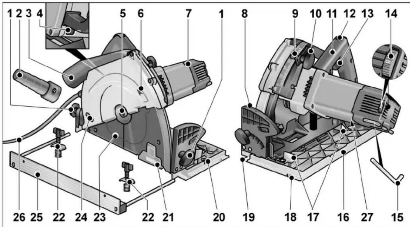
1 Toggle screw for setting the mitre angle
2 Universal adapter for suction hose with snap connection (Ø 32 mm)
3 Swarf ejector/connection piece for external extractor
4 Sp i n d l e l
5 Clamping screw/Clamping flange
6 Direction of rotation arrow
7 Motor housing
8 Scale for metre angle
9 Scale for setting cutting depth
10 Toggle screw for setting the cutting depth
11 Handle
12 Switch interlock for switch
13 Switch
14 Dial for preselecting the speed
15 Hexagon-socket key
16 Saw bench
17 Lever for -1^ -setting
18 Inner/outer guide groove
19 Cut mark (0^ / 45^)
20 thread k for attachment of parallel stop
21 Moveable window
22 Wing screw/clamping bracket/ spring * for attachment of parallel stop
23 Guard hood
24 Opening for setting the riving knife
25 Parallel stop
26 5.0 m power cord with mains plug
27 Rating plate
* o p t i o n a l
Technical specifications
| Machine type | CSE 55 T | |
| Mains voltage V/Hz 230/50 | ||
| Protection class | II/☐ | |
| Power input W 1350 | ||
| Idling speed r.p.m. 2600-5200 | ||
| Cutting rate m/s 22-44 | ||
| Saw blade-shaft thread mm 20 | ||
| Saw blade-diameter (max/min) mm 160/149 | ||
| max. cutting width | mm | 1.8 |
| Cutting depth | mm | 0-55 |
| Cutting depth with guide rail * | mm | 0-49 |
| Mitre cut | -1°-48° | |
| Weight according to “EPTA Procedure 01/2003”(without power cord) | kg | 4.0 |
* o p t i o n a
Instructions for use

WARNING!
Before performing any work on the electric power tool, pull out the mains plug.
Before switching on the power tool
Unpack power tool and accessories and check that no parts are missing or damaged.

CAUTION!
The mains voltage and the voltage specifications on the rating plate must correspond.
Attaching or changing the saw blade

NOTE
It is recommended to use only circular saw blades which FLEX offers for use with this machine.
Pull out the mains plug.
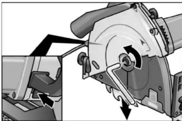
Press and hold down the spindle lock.
Loosen clamping screw anti-clockwise using enclosed Allen key.
- Unscrew clamping screw (1) and remove front clamping flange (2).
Take saw blade (3) downwards out of the housing.

CAUTION!
- Note installation position of back (4) and front clamping flange (2).
The cutting direction of the teeth (direction of arrow on the saw blade) and direction-of-rotation arrow on the housing must agree.
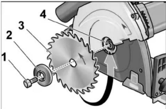
Clean rear (4) and front clamping flange (2) as required.
Insert saw blade from below into the housing.
- Attach the front clamping flange (2) with the flange on the outside and manually tighten the locking screw (1) in a clockwise direction.
Press and hold down the spindle lock. Tighten clamping screw (1) with Allen key.
Setting the riving knife
CAUTION!
Never operate the plunge saw without.
theriving knife.
The riving knife prevents the saw blade from jamming when cutting lengthwise.
To ensure this function, the riving knife must be set correctly (see diagram).
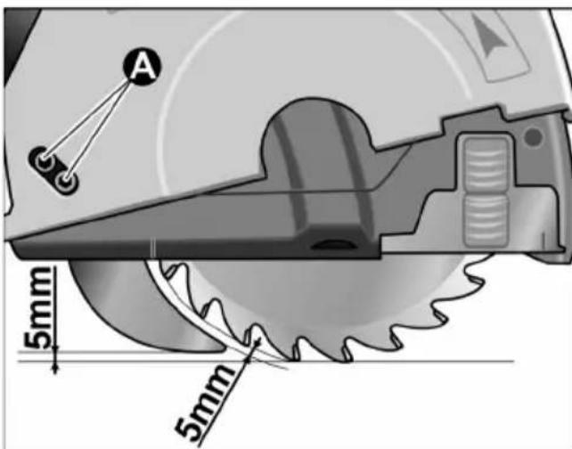
Whenever the saw blade is changed, check the setting of the riving knife.
To adjust the riving knife:
Set maximum cutting depth (see there).
Press switch interlock upwards and swivel in saw bench completely.
Two cheese-head screws for setting the riving knife (A) are visible in the housing opening.
Loosen both screws using the Allen key.
Set riving knife correctly.
Tighten two cheese-head screws.
Swivel back saw bench.
Dust extractor

WARNING!
Dust released from materials, such as lead paints, some types of wood, minerals and metal, may be hazardous to the operator orpeople in the vicinity. Inhaling or touching these dusts may result in respiratory diseases and/or allergic reactions.
-Ensure the work place is well ventilated!
-If possible, use external dust extraction.
-It is recommended to wear a respirator mask belonging to filter class P2.
Prevent dust from accumulating at the workplace. Dust can easily ignite.
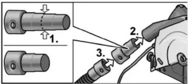
Shorten universal adapter at the 2nd stage (1.).
Insert universal adapter into the connection piece (2.).
- Attach extraction hose to the adapter.
Connect extraction hose to the dual extraction system.
Follow the operating instructions for the dust extraction system! Check the attachment!
Setting the cutting depth

NOTE
To ensure optimum cutting results, thecutting depth should be 2-5 mm greater than the material thickness to be cut.
Pull out the mains plug.
Loosen toggle screw of the cutting depth setting.
Set required cutting depth on the scale.
Tighten toggle screw.
The saw plunges maximum as far as the preset cutting depth.

NOTE
When working with the guide rail (optional accessory), the area of the cutting depth setting pointer marked with "GRS" must be used!
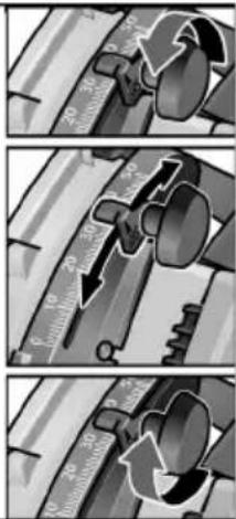
Setting the litre angle

NOTE
In the case of litre cuts, the cutting depth is less than the value displayed on the scale for the cutting depth.
Pull out the mains plug.
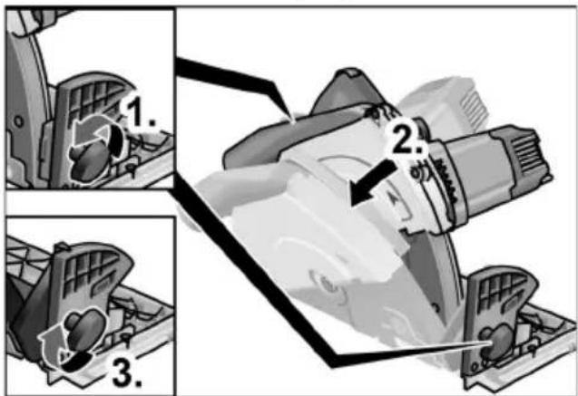
Loosen the T-screws (1.).
Set required litre angle with the aid of the scale (2.).
Tighten the T-screws (3.).
-1°-setting

NOTE
By positioning the saw blade at a slight angle, a tear-free undercut is obtained on the undersides of the board. After the underside of the board has been turned face up, these undercutts produce a perfect narrow gap when they meet.
Pull out the mains plug.
Loosen toggle screws for the mitre angle setting.
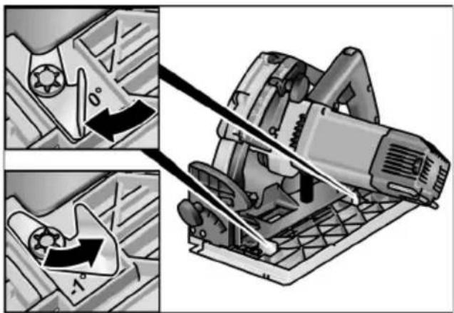
Swing round both levers for -1^ setting. The selected setting becomes visible (-1^)
Tighten the T-screws.
To reset to the 0^ position:
Loosen toggle screws for the mitre angle setting.
Swivel saw a little ( 5^)
Swing round both levers until "0" becomes visible.
Swivel back saw bench.
Tighten the T-screws.
Speed control
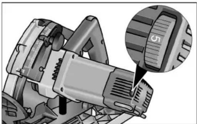
The thumb wheel can be used to steplessly vary the speed from 1 (low) to 6 (high) even while the power tool is running.
As a result, the cutting speed can be optimally adjusted to the particularly material and to the working conditions.

1 | 2600/min
2 3150/min
3 3700/min
4 4200/min
5 4650/min
6 5200/min
Switching on and off

CAUTION!
For reasons of safety the switch is not locked and must be held down during sawing.
The switch interlock prevents the power tool from being switched on unintentionally and locks the guard.
Initially always switch on saw in working position.
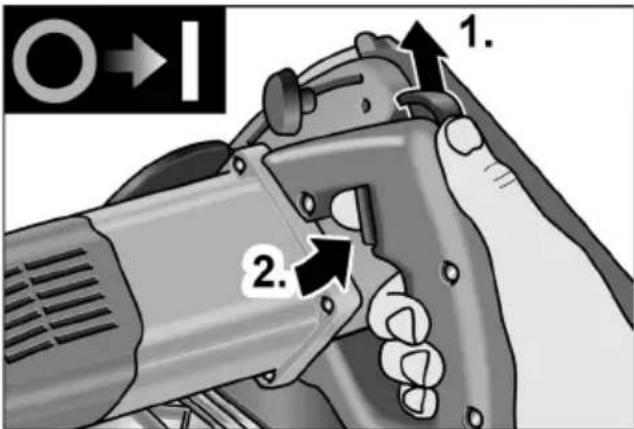
Press up and hold down the switch interlock (1.).
Press and hold down the switch (2.).
Release switch interlock (when the saw has been plunged).
Switching off:
Release the switch.
Parallel stop (optional).

WARNING!
Before performing any work on the electric power tool, pull out the mains plug.

NOTE
Before the saw can be placed in the supplied transportation case, the parallel stop must beremoved.
The parallel stop can be attached on the left or right in the direction of thrust of the saw.
The stop edge can be attached above or below.
Stop edge upwards Increases the contact surface of the saw bench.
Stop edge downwards Facilitates cutting parallel to the workpiece edge.
Attaching parallel stop:
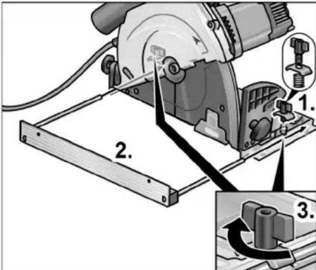
- Attach wing screw/clamping bracket/spring for mounting the parallel stop (1.).
Insert parallel stop (stop edge up or down) and set to required width (2.).
Tighten the wing screw (3.).
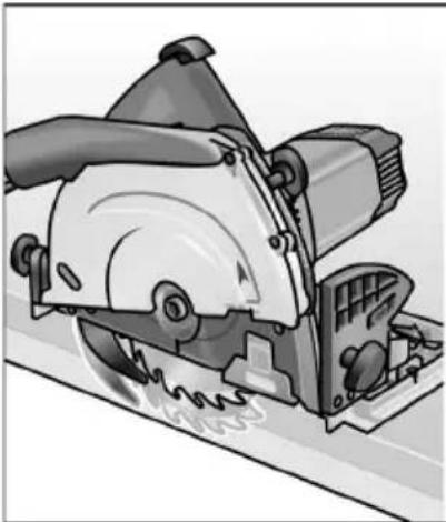
Guide rail (optional).
A guide rail (800 or 1600 mm long) is available from any FLEX customer service centre.
To extend the guide length, 2 guide rails can be connected to each other.
To do this, a connector is available from any FLEX customer service centre.
Fitting the connector:
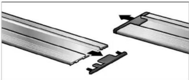
Remove protective caps from the guide rails.
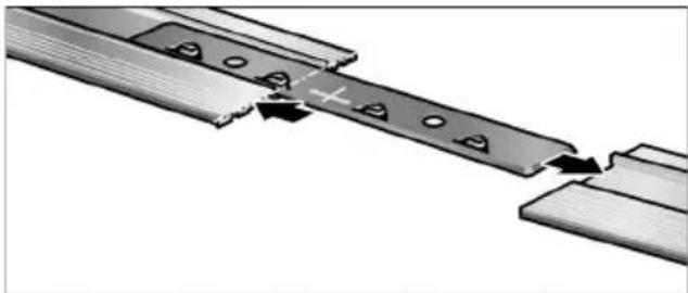
Push connector halfway along the guide rails.
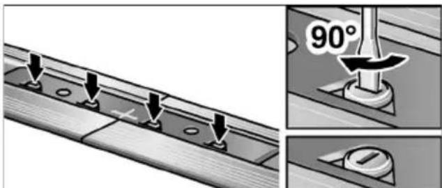
Clampcams (4x)
"Sawing in" the guide rail:

NOTE
Before using the guide rail for the first time, cut the anti-splinter shoe to the required width. It is recommended to use a new saw blade.
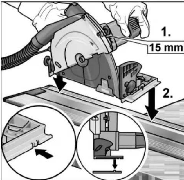
Setmitreangleof 0^
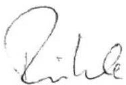
Set cutting depth to 15mm (1.).
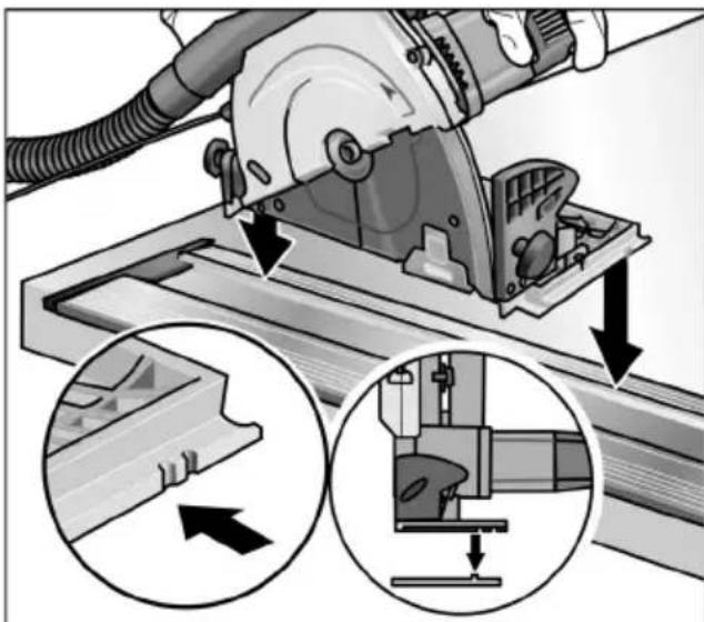
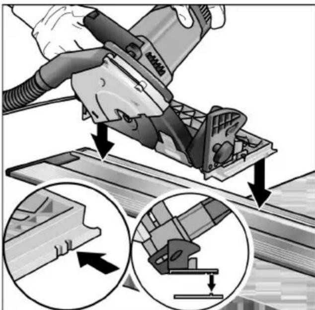
Place guide rail on a stable, level support ensuring that the anti-splinter shoe projects at the front.
Switch on saw.
Place saw with the inner guide groove on the guide rail (2.).
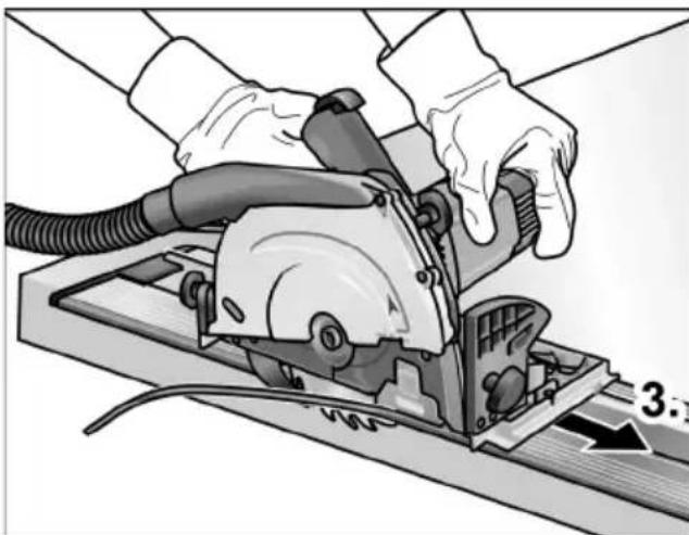
Feed saw evenly in the direction of the cut as far as the end of the guide rail (3.).
Using the guide rail

NOTE
When placing the saw on the guide rail, always use the guide grooves.
Inner guide groove ("0"):
litre angle 0^ / - 1^
Outer guide groove ("45"):
litre angle >0^
Scoring with the guide rail
To prevent the surfaces of board materials from splintering, they can be scored at a litre angle of < 4^ .
Setmitreangleofapprox. 4^
Set cutting depth to approx. 3.3mm
Place saw with the inneguide groove on the guide rail.
Score board.
Setmitreangleto 0^
Set cutting depth to full material thickness plus 3mm
Place saw with the inneguide groove on the guide rail.
Saw through full board thickness.
Working with the power tool

CAUTION!
After the power tool has been switched off, the saw blade continues running briefly. When the rotating saw blade touches the workpiece, the power tool may recoil

NOTE
Excessive feed reduces the performance of the power tool, impairs the cutting quality and reduces the service life of the saw blade.
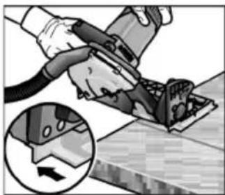
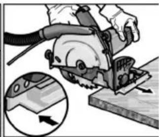
Sawing along a scribe mark
Connect extraction hose.
Set cutting depth to the required dimension.
If required, set litre angle.
Insert mains plug.
Switch on dust extraction system.
Hold the handle with your right hand.
Place saw bench on the workpiece.
Push down inspection window as far as the workpiece surface.
Switch on saw and wait until the saw blade has reached the maximum speed.
Press down saw as far as the stop of the cutting depth limiter.
Slowly feed the saw along the material.

NOTE
The cut marks on the saw bench show the position of the saw blade for a right-angle cut.
Feed the saw evenly through the material.
After cutting:
- Switch off the saw. Saw blade continues running briefly!
- When the saw is lifted, the saw blade returns to the initial position and the guard is locked.
At the end of work:
Thoroughly clean the electric power tool and accessories.

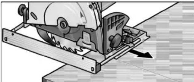
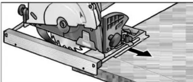
NOTE
To process large workpieces or to cut straight edges, you can also attach a bar or similar implement to the workpiece and guide the circular saw with the saw bench along this auxiliary stop.
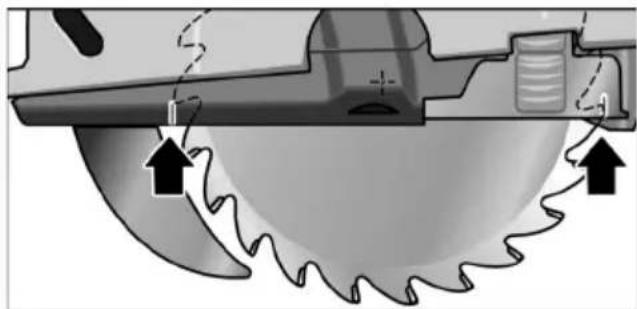
Plunge cuts

CAUTION!
-For plunge cuts the litre angle must beset to 0^
Take suitable precautions to prevent akickback, e.g. fix a wooden block on the workpiece behind the machine.
The sequence for making plunge cuts can be found in the section "Sawing along a scribe mark". The litre angle must be 0^ .
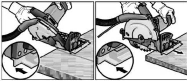
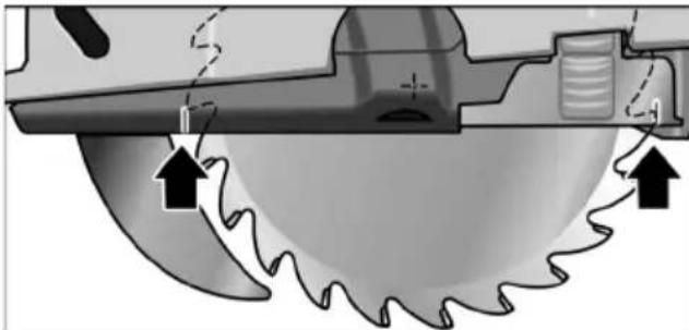
To improve orientation when making plunge cuts, marks are attached to the inspection window and the guard (see diagram).
These marks identify the cut area of the fully plunged saw blade (at maximum cutting depth).
Maintenance and care

WARNING!
Before performing any work on the electric power tool, pull out the mains plug.
Cleaning the electric power tool

WARNING!
Do not use water or liquid detergents.
Regularly blow out the housing interior and motor with dry compressed air.
Clean saw bench and setting devices using a vacuum cleaner and paint brush.
Occasionally spray joints with machine oil.
Also clean the guide rail, otherwise the saw will not be guided properly resulting in an inaccurate cut.
Repairs
Repairs may be carried out by an authorised customer service centre only.

NOTE
During the warranty period do not loosen the screws on the motor housing. Non-compliance will deem the guarantee obligations of the manufacturer null and void.
Spare parts and accessories
Other accessories, in particular insertion tools, can be found in the manufacturer's catalogues.
Exploded drawings and spare-part lists can be found on our homepage:
www.flex-tools.com
Disposal information

WARNING!
Render redundant power tools unusable byremoving the power cord.

EU countries only
Do not throw electric power tools into the household waste!
In accordance with the European Directive 2002/96/EC on Waste Electrical and Electronic Equipment and transposition into national law used electric power tools must be collected separately and recycled in an environmentally friendly manner.

NOTE
Please ask your dealer about disposal options!
C ∈-Declaration of Conformity
We hereby declare that this product corresponds with the following standards or normative documents:
EN 60745 in accordance with the regulations of the directives 2004/108/EC, 2006/42/EC, 2011/65/EC.
Responsible for technical documents:
Manager Research & Development (R & D)

Oliver SchneiderEckhard
Manager Quality
Department (QD)
09.07.2012
When a new machine is purchased, FLEX issues the end user with a 2-year manufacturer's warranty which comes into force on the date the machine was purchased.
The guarantee covers only defects which can be attributed to a material and/or production fault as well as non-performance of warranted characteristics. When making a claim under the guarantee, enclose the original sales receipt with purchase date. Repairs under the guarantee may be carried out only by workshops or service centres authorised by Flex. A claim may be made under the guarantee only if the power tool has been used as intended. The guarantee excludes in particular operational wear, improper use, partly or completely dismantled machines as well as damage caused by overloading the machine, use of non-permitted, defective or incorrectly used application tools. Damage which is caused by the machine on the application tool or workpiece, use of force, consequential damage which can be attributed to improper or inadequate maintenance on the part of the customer or a third party, damage caused by external effects or foreign objects, e.g. sand or stones, as well as damage caused by non-observation of the operating manual, e.g. connection to an incorrect mains voltage or current type. Claims for insertable tools or accessories can only be made under the guarantee provided they are used with power tools for the intended or permitted use.
Exemption from liability
The manufacturer and his representative are not liable for any damage and lost profit due to interruption in business caused by the product or by an unusable product. The manufacturer and his representative are not liable for any damage which was caused by improper use of the power tool or by use of the power tool with products from other manufacturers.
Table des matieres
Symbolesutilisés 31
Pourvoiresecurite 31
Manager Research & Development (R & D)

Oliver SchneiderEckhard R
Manager Quality
Department (QD)
09.07.2012
Manager Research & Development (R & D)

Oliver Schneider Manager Quality Department (QD)
09.07.2012
Manager Research & Development (R & D)

Oliver SchneiderEckhard
Manager Quality
Department (QD)
09.07.2012
EN 60745 de acordo com as determina-oes das directivas 2004/108/CE, 2006/42/CE, 2011/65/CE.
Responsavel pela documentacao的技术e: FLEX-Elektrowerkzeuge GmbH, R & D Bahnhofstrasse 15, D-71711 Steinheim/Murr
Manager Research & Development (R & D)

Oliver Schneider Eckhard R
Manager Quality
Department (QD)
09.07.2012
De invalidaag CSE 55 T is bested
Manager Research & Development (R & D)

Oliver SchneiderEckhard
Manager Quality
Department (QD)
09.07.2012
Savning after forskaering
Manager Research & Development (R & D)
09.07.2012
Manager Quality Department (QD)
Garanti
Endast for EU-stater
Manager Research & Development (R & D)

Oliver SchneiderEckhard
Manager Quality Department (QD)
09.07.2012
Manager Research & Development (R & D)

Oliver SchneiderEckhard
Manager Quality
Department (QD)
09.07.2012
TeVTwOeToEKKEvTpo (4 opec).
"Kópsio" tnc páyac odynoncs: YIIOAEIEH
Piv Tnv npwtn xpon tnC pavyac
Oynonnc npenla va konie n npoataia
Oaonc ypceiwv o anaitoumu evo nlatoc.
Suviooue Tn xponkaiovopyiac
Aenida c Konnc.
PuθμioTe γωvía λοξóμησός 0°.
PuθμioTe βαθoc konnc oε 15 mm (1.).
Avtaaakia kai eapntnata
Tia nepaiepwoeapntmaata,iaitepa yia
epyaia xipnonc, mnpci va avatpeEET
oTouc kataoyouc tou kataokeuaoTn.
xiedia anouvapuooynuevnc oyncs
kai iotec avtaalaktkwv 0a bpTe
OTNV IOTooeia mac:
www.flex-tools.com
Yπoδεiξειç anóuροης

IPOEIOIHSH!
Axyonoteue ta naia uynxavnmuata nou v xonaiomoiouvtai nEv, kobovtac to tpofootiko kaawio.

Móvo yia xópeç tnc Eupwnaiknca Evomega
Mny nTATE ta nEeKTPiKa epyaia Ota oikia anaoppmuata!
Baoi Tc Eupwnaikn Odyia c 2002/96/EK
πepi nEeKtpiKwV kai nEeKtpovikwV pAliw
oukεuWv kai mXavmuaTswV kai Tnv
εφapuoyn TcOTo eViko δikaio, ta
axpnoTa nEeKtpiKa epaaleia npénei va
oulambdaevovtai xwiota ka va oBnyouvtai oE
phiikn pOcTo nepiβalov enavaIionoiOn.

YIIOAEIEH
Manager Research & Development (R & D)

Oliver Schneider Manager Quality Department (QD)
09.07.2012
Manager Research & Development (R & D)

Oliver SchneiderEckhard
Manager Quality
Department (QD)
09.07.2012
EN 60745, a 2004/108/EK
a 2006/42/EK, a 2011/65/EK
Manager Research & Development (R & D)

Oliver Schneider Manager Quality Department (QD)
09.07.2012
Manager Research & Development (R & D)

Oliver Schneider Manager Quality Department (QD)
09.07.2012
Tehnilised andmed. 241
Kasutusjuhend 242
Manager Research & Development (R & D)

Oliver Schneider Manager Quality Department (QD)
09.07.2012
Manager Research & Development (R & D)

Oliver Schneider
Manager Quality
Department (QD)
09.07.2012
2004/108/EK, 2006/42/EK,
2011/65/EK noteikumiem.
Par tehnisko dokumentaciju atbild:
Manager Research & Development (R & D)

Oliver SchneiderEckhard
Manager Quality
Department (QD)
09.07.2012
UyMbI IN Bn6paunr 284
O6nBn 285
TexHnueckne daHHbIe 286
HctpyKnno 3Kcnnyataun .287
TexobcnjxKuBaHne u yxo.. 294
Yka3aHnNo yTnIIn3aunn 294
COOTBeTCTBHe HopMaM C 295
TapaHTIN 295
IcnoJb3yeMbIe cIMBOJIbI

NPEUYPEXKDEHNE!
TOT CMBON 063Haayet HnocpeCTBeHHO yrpoKaioyIO OnaCHOCTb.
HeBbINOJIHHeHne 06O3HaueHHOro TaKIM O6pa3OM yKa3aHnM MoXeT NOBJeYb 3a CO6oI TJaXeJIbIe TeJIeCHbIe NOBpeJKeHnI INI DaJKe CMePb.

BHIMAHHE!
TOT CUMBOI 0603Haayet BO3MOXHOCTb BO3HNIKHOBEHNAOCHOH CHTyaUN.
HeBbINOJIHHeHne 06O3HaueHHOro TaKIM O6pa3OM yKa3aHnM MoXeT NOBJeHy 3a c6oB TeJIeCHbIe NOBpeKdEHNr INI MaTePnaJIbHbIyUep6.

YKA3AHVE
Iod 3aIIOBkOM npNBOJTCpeKomeHdaunno npabnIbHomy pImMeHeHIO n BaxHa HOpMaun.
CnMBoJIbHa npI6ope

Ipeed BBODOMB 3KcIIyaTaUIO npOHTITE HnCTpyKuNIO NO 3KcIIyaTaUIN!
HaedeHbTe 3aunTHbIe OyKn!

Ponb3yITeCb npucno6JeHnMaJN 3aunTbI opraHOB cnyxa!

Yka3aHnno yTuNn3aunn OTCJyXHBxxCBOI
cpoK 3JIeKTpO npnBopOB
(cmOTpuTe Ha cTpaHnue 294)!
CoxpaHnTe,NoXaJyNCTa,JaHHyIO INHCTpyKuIIO B HAdExKHOM MeCTe IJI NaOpJeDyIOoEro NcNOJb3OBAHnA.
MeToDbIpacnna
ONACHOCTb: He np6JInxkaIte pyKn K 30He paCnJa N K nnJbHOMy DnCKy. YdepxkBaIe BTOpOy pyKoIdoNoJIHnTeJbHyIO pyKOaTKy IIN KOpNyc DnIraTeJIa.
YdepxnBaI nnly o6eIMn pykamn, Bbl n36eraTe onaChocTn nobpeKdEHHy pK NNbHbIM dNcKOM.
He onyckaIte pykn noD o6pa6aTbIBaemoe n3dJIne.
3aHTbIK KOxyH He MoKET 3aHTbBac noI o6paTaIBaEMbIM n3dJIeMOT NIIbHO DnCKa.
■ПиВeДИТe ГЛуБИнHy pe3aВ COOT-BETCTBnE C TOJIUNHOn O6pa6aTbIbAe-MOTO N3dJIInJ.
Iod o6pa6aTbBaembIM N3dJIeM 3y6bJdoJIxHbIBuHHeTbcr He B NOJHyIO BlicOTy.
HnB Koem cIyuae He depKnte 6pa6aTbIbAemoe n3deJne npn paCnJIe B pyKe IJn Ha Hore. 3akpenTe 6pa6aTbIbAemoe n3- deJne B cTa6NJBHom npncnocO6- JENn dJa FHKcaUIn.
Baxho xopoio 3aKpeNt b
obpa6aTbIbAeMoe n3JeHne, yTo6bl
cokpaTntb DO MNHMMyMa ONaCHOCTb
fN3nueCKOro cOpnKOCHOBeHNr,
3aKJIINHBaHH NIIbHOrO DnCKa NJIIN
NOTepn KOHTpOI.
ДерхиTe 3ЛeКТponHcTpymeHT TOЛьКо 3a ИЗОЛИрOBaHHbIe NOВepx-HocTn pyKoTKn, ecЛи BblBbINOLHReTe pa6Otbl, BO BpeM KOTOpbIX pa6OчИ NHcTpymeHT MOXeT 3aДeTbCKpbITbIe 3ЛeKТponpOBoDA ИЛN CO6CTBeHHbI WHyp 3ЛeKТpo-NTaHЯ.
Pn KOHTaKTe C HaxOJaUIMcM NOHa npJxKeHnEM npoBODm MeTaJIINYeCKNe DeTaN 3JeKTPoHCTpyMeHTa TaKx OKa3bIbAIOCTnOd Ha npJxKeHnEM, YTO MOKeT nPnBeCTN K NopaxHeHIO 3JeKTPuYeCKM TOKOM.
IcnoJb3yTe npn npoDoJbHOn paCnIOBKe Bcerda ynpn nn npaMyO HApBaJIooSyIO KpOMKn. 3TO cNooc6CTByeT NOBbIeHNIO TOHOCTN paCnJa NCHKaet BepoAHTHOCTb 3aKJIINHBaHnI NJIbHOrO DnCKa.
IcnoJb3yIte Bcerda nIIbHbIe NnCKn HaJIeXaIeN BeINuHNbIC COOTBeTCTBYIOUIM NOCAOHybIM OTBepCTnEM (HaNP., 3Be3DOo6pa3HOI IN KpyrLoIΦOpMbI).
IpOBePraTe nepeKaKdblm NcNoJIb-3OBaHHeM, 3aKpbIT JN 3aUHTbI KOKyX HaJLExKaUIM O6pa3OM. He nCnoJIb3yIte Nnly, ecN 3aUHTbI KOKyX He DnBraETcA CBO6oDHO Hn He 3aKpbIbAEtca3y. Hn B Koem cIyuae He 3axImaIte N He npNBra3bIbAaTE 3aUHTbI KOKyX; NNbHbI DNCK B pe3yJbTaTe 3TOrO OCTaeTcHnUeHHbIM.
B clyae cnyaHoro naeHnna Hnbl Ha nol 3aunTHbI KOxyx MoKet nOrHyTbcy. Y6eNTecb B TOM, yTo 3aunTHbI KOxyx CBO6OJHO dBnraeTCn Hn KacaETcH Nn nnbHoro DnCKa, Hn dpynx 3JIemEHTOB npn BCEx yJax n rny6nHex npoNla.
PpOBeBte COCToHHe n cyHKuHIO npyKnHbI dJa 3aunTHoro Koxyxa. B clyuae HeucnpaBHoro cyHKcUHO npBaHna 3aunTHoro Koxyxa n npyXnHbI nepeNcnoJb3OBaHneM nnJIbI Tpe6yeTcra npOBeDeHne TexHueckoro o6cJyKnBaHna.
IOBpeKDeHHbIe 3JIeMeHTbl, JINKHe OTIOXKeHnI INI CKONJIeHne CTPyKKn 3aMeJJIOT 3a6OToH NIXKHeRo 3aUHTHO KOKyxa.
Pn «NorpyxHOM npoHne», KOTOpbIi BblIOJIHaTeCHe NOd npaMbIM yrIOM, 3aΦnKcnpuTe OOnpHyIO nHTy NIIbI B ueJax npeDoTbpaueHHa 6OKOBOrO CMeueHna.
BOKOBoe CMeueHne MOKeT npNBecTN K 3aKJIINHbAHnIO NIIbHOrO DNCKa I B pe3yIbTaTe 3TOrO K OTdaYe.
He KlaaIte NJIy Ha pa6oUH cToJ
NIIHa NOJ, ECNI NNbHbIM DNCK
He 3aKpbIT 3aunTHbIM KOxYXOM.
He3aIeHHbIM, DBnraIOuINcR
No INhePUNI NNbHbIM DNCK DBNrAeT
NJIy IpOTNB HApBaBJeHNr pe3a n
NNlNT BCE, YTO IOnaJaTeCn Ha NytN.
O6paTIte BnHMAnHe Ha OTpe3OK
BpeMeHn pa6oTbI NNblI NO INHePcUN.
He npn6JnxKaIte pyK K Bbl6pocy cTpyxKn.
Bpaaioiue 3JeMeHTbI MOryT npaHnTb Bac.
He pa6oTaIe, yIepXnBaI nIy Hau roJIOBOi.
Takoe noJoxKeHne He oBeCneuNbAeT Bam doCTaToCHoro KOHTpOJI NaI 3JIeKTPoINHCTpyMeHtOM.
He nCnoJb3yIe 3JeKtpoHCTpyMeHT B CTAUHOHApHOM NOLOXKeHN. OH He cKOHCTpyuPoBaH DJIa 3KcNJaYaTaUzHN Ha NINbHOM CTOJIe.
He nCNoIb3yIe nnJbHbIe dNcKn n3 6bIcTropexKyuIe cTaJI (HSS). TaKne nnJbHbIe NcCKn MOrYT JIeKo CJOMaTbCra.
He nIInTe XeJIe3HbIe MeTaJIbI. PackaJIeHHa nCTpyXka MoKcT npINBecTI K BO3rOpAHnIO acnnpauCNOHOrOyCTPOIcTBA.
HapjkeHne B cetn 3HaueHne HApjKeHn, npBedeHHoe Ha cnpMeHHO TabJnueKe annapaTa, o8aTeJb-HO DOJIKHbI COBnaAdTb.
Wymbln Bn6paunr
3HaueHn ypoBn IyMa n Bn6paun 6blnn onpeJeHbI corJaCHO HopMaTHBHOJ DOKymeHTaun EN 60745.
I3MepeHHbI yPoBeHb 7yMa daHHoro npnbopa no 7kaJe A coCTaBnReT npn O6bUHbIX ycOBnX 3KcPJIyaTaCuIN:
-
YpoBHeHb 3Byka: 92 d6(A);
-
YpoBHeHb 3ByKOBOI MOUHOCTN:
-
NorpewHocTB: K = 3 έB.
O6uee 3NaueHne Bn6paun:
- 3haueHne Bn6paun: a h < 2,5 M/ceK² - IorpeuHocTB: K = 1,5 M/ceK

BHIMAHHE!
PnBBeEHbIe 3Iecb pe3yIbTaTbI N3MepeHn DeiCTBNTbHb IINb IJIa HOBbIX np6opOB. Pn exKeIHeBHOM IcNoJIb3O-BaHN 3HaueHn IwMa I BNbpaun N3MeHAIOTCA.

YKA3AHHE
YKa3aHbI B DaHHo INHCTpyKcUu yPoBeHb BN6paun 6bl ONpeJeEn CTAHdApTN3npoBaHHbIM MeTODOM N3MepeHn, npBedeHNbIM B HopMaTINBHO JOKyMeHTaUEN 60745, n MoKeT 6blt NcNoJIb3OBaH npCpaBHeHn 3JleKTPoIHCTpyMeHTOB dpyr c dpYrom. OH npriOdoen TaKxe dJa npEeBapNTelbHO UceHKN BN6paUHOHHO HaPuy3Kn.
PnBHeHbI 3decb yPoBeHb Bn6paun BO3Hkaet npn nCNoJb3OBaHn 3JeKtpOnHCTpyMeHTa NO OCHOBOMy Ha3HaueHIO. Ecnn Jze 3JeKTPoHNCTpyMeHT 6ydet Nc-NOJb3OBAtbcr He IIO Ha3HaueHIO, B KOMIIeKTe C pa6OuHMn INCTpyMeHTamN, OTnUauOIMMnC r O peKOMeHdyEmbIX B DaHHo INHCTpyKUIN, IIN PnI HeDOCTaTOHOM TexobScnyxHBAHN, TO cKaKTNUeCKN yPoBeHb Bn6paun MoKeT OTnUauTbcr OT npBHeDENHO B daHHo INHCTpyKUIN. B 3tOM cIyuae Bn6paUNOHnHa HarpY3Ka B paChTe Ha BCIO npOdoJXntbHOCTB pa60tbIC INHCTpyMeHTom MOKeT 3HaunTeJBHO NOBbICITbcr. DJIra ToHHOro ONpeDeHENH Bn6paUNOHnHa HarpY3Kn Heo6xOIMTOkKe YUnTBaTB Bpemr, B TeueHne KOTOpOropocTcR BblKJIooHbIM IIN pN6Op BKJIIOyeH, HO He NCNoJb3yETcA JRA BblONHeHnPa60tbl. B DaHHom cIyuae Bn6paUNOHnHa HarpY3Ka B paChTe Ha BCIO npOdoJXntbHOCTB pa60tbIC pN6Opom MOKeT 3HaunTeJBHO CHN3NTbcr. PpIMITE, NoXaIyIcTa, DOonlHHTeJbHbIe Mepbl NO 3aUIne POJb3OBaTeJIr OT BpeHoro BO3dEInCTBnBn6paun, HaPnpMep: peryJlrphoe npObeHne Texo6ClyXHBANr 3JeKTPoHNCTpyMeHTa n pa6OuNX INHCTpyMeHTOB, CO3daHne BO3MOXHOCTI NOJb3OBaTEJIIO BCEgDa depXkTaB pyKN B TeJIe, YeTKaI opraHn3aUIN pa6OuHX IIPOUCCOB.

BHIMAHHE!
Pn akyctnuecko Haarpy3Ke Cbbiwe 85 d6(A) cneJeT noIb30BaTbcn npuCnocobJeHnAMN IJIa 3aunTbI opraHOB cJyxa.
O6uBn
1 TnCKOBbl BnHT dJa peRyIuPObKn yrJa cKoca
2 y H n BepcaJIbHbI a, UMOHHOrO ⅢJaHra c XpaNoBbIM COeINHeHnem (0 32 MM)
3 Bb6poc ctpyKKn/ CoeHNHTeIbHbI naTpby6ok dJa 3KCTepHOro acnnpaUHOHHoro yCTpoiCTBa
4ФИКcaTOPшнндя
5 3axmmHOB BVHT/3axmmHOHФланц
6 CTeJka, yKa3bIbAIOUaHnPaBJeHne BpaSeHnA
7 Kopnyc DBrGaTeJIa
8 Shkajda Jyrga ckoca
9 ⅢkaJa dIypeRyIInpOBKn rIy6HbI npOnnla
10 TnCKOBbI BnHT yCTaHOBKn rJy6nHbI npOnnla
11 PykoTka
12 BLOKINPOBka BKJIIOUeHnBAblIKJIIOuHaTeJRA
13 BbIKIOHaTeJIb
14 KoIecO yCTaHOBKn YnCna o6OpoTob
15 WeecTnrgpaHbI KJIou
Hapopopa Nnblb
17 PbyarДЯ yctaHOBKn -1°
18 BHyTpEHHN/BHeuHn HappaBIAO- uin na3
19 Pa3MeTkn nponnla (0^ / 45^)
20 Pe3b6a
Дя Креленя пааллевно унopa
21 IpeBnKHOe cMOtpoBOe OKHO
22 KpbIbTuBn BnHT/3aXmHa ncko6a* IJI KpeIeHn npaJIeJbHoro ynpa
23 3aunTHbIK KOxUx
24 OTBepCTne IJy yCTaHOBVKn paCnOpHoro KJIHa
25 NapalJIeIbHbI ynpop
26 CeTeBOH uHyp 5,0 M co uTencelb-HO H BuJKOH
27ФирмehнТа6ЛУкa
TexHnueckne daHHbIe
YTo6bI npeDoTbpaTHTb 06pa3ObaHne cKoJIOB Ha NOBepXHOCTM MaTePnaJIOB PINT,MOxHO BblIOJHHTb Ipope3aHHe NOD yrJOM CKOCA < 4^
YCTaHOBnTe yrOJI CKOCA BeJIuHHO np6J.4°
YcTaHOBnTe rIy6nHy npOnnHa npn6J. 3.3 MM.
YcTaHOBInTe NnIy BHyTpEHnM HAppaBJIIOUIM Na3OM Ha HAppaBJIIOUOuO uHv.
■ Nopexbte nIHTy.
YcTaHOBnTe yrOJ cKoCa Ha 0^
YcTaHOBInTe rIy6nHy npOnnHa nOJIHyTOJIuHv MaTePnAJa PIIoc 3 MM.
YcTaHOBnTe NnIy BHyTpEHHm HaPaBJIIOUIM Na3OM Ha HApBaJIHOuOyIO uHv.
Pacnnte nHTy NO BcEN TOJIUNHe.
Pa6ota c 3JIeKTpOINHCTpyMeHTOM

BHIMAHHE!
- Pocne BbIKIOueHnI NIIbHbI INCK eie HeKOTOpoe BpeMa IpoDoJIkaeT BpaaATbcn IO INHePcun.
- B cIyuae kacaHnBpaaioMmCnIb-HbIM nCKOM oBaTaBAemOro N3dJIIN M0KET npON30HT OJaHa.

YKA3AHHE
CnHkOM CNbHOe npoDbXKeHne BnpeD CHNkaet MOHocTb npbopa, yxuiaet KaueCTBO paCnna n COKpaaet cPOK cnK-6bl NnIbHOrO DnCKa.
PacnIIOBka no pa3MeTke
I OndcoeHNHTe acnnpaunHbI JlaHr.
YcTaHOBnTe rIy6uHy npOuHa Tpe6yEmyU BEnuHy.
Pn Heo6xOIMOCTu yCTaHOBNTe yrOJCKOca.
BctaBbTe BnIky B po3eTKy.
BkIIOHTe acnnpaunOHHy yCTaHOBky.
Bo3bMITEc6 3a pyKoTky npaBOy pyKOi.
YcTaHOBnTe ONopy NnIbHa o6pa6aTbIbAeMOe N3dJIe.
IpeeBnHbTe CMOTPOBOE OKHO K NOBepx-HOCTN 6pa6aTbIBaEMORIO I3JeJIN.
BkIIOUHTe NIIy IN NOOJXdITe, NOKa NNbHbIN DnCK HaBepeT MaKcIMMaJIbHOe YnCNo O6OpOTOB.
PnJxMnte Nny Bn3 do ynpa orpaHn- nTeJI rIy6nHbI npOnna.
BBeIte NnJy MeIeHHO B MaTePnaJ.

YKA3AHHE
Pa3MeTkn npoHnla Ha onope nIbI noka3bBAIO TNOJoxHe NIIbHOrO dNcKa npnnpaMOyrolbHom npoHne.
■ Beinte niny uepe3 MaTePnaJ, npoDbnraacb paBHomepHo.
IocJe OKOHuaHnpe3KN:
- BbIKIIOHTe NIIy. NIIbHbI dNCK BpaaTc8 eue HeKOTOpoe BpeM!
e PnnoHHTnn NJIbI NJIbHbIN DnCK BO3BpaaetcO6paTHOB INCXoHoe NOJIOXKeHne n 3aunTHbIK KOKyx 6loKnpyETc.
IocJe OKOHuaHnpa6oTbI: IOnuCTnTe TuaTeJbHo 3JIeKtpOnHcTppy-MeHT IN PpHaJaJIeXHOCTN.

YKA3AHNE
Длгобаботкбьшхи3дeлнилпpeЗкпрЯмьх кромok Bы може тakkeприкpenntb панку пиюобнй рapedmetКобабатыаemomy n3deлноиВECTNцИркУларHyIO ПИЛСОпОПиЛБIВДЛБ 3TORO BCПOMORAteJьHOrO yNopa.
NorpyyKhble nponnbl

BHIMAHHE!
- Pn norgyKbIX npOnnax yroI cKocacJeNyET yCTaHOBNTb Ha 0^
- PpIMnTe COOTBeTCTByIOUne MepeI IpeIOCTOpOxHocTN dJIa IpeIoTbpaue-HnA OTdauN,HaNP.,3aФNKcnpyIte DepeBHHbI bpyc n03aI npi6opa Ha o6pa6aTbIBaEMOM N3dJIIN.
Ipocecc BbINOJIHeHnI NorpyxHbIX npoINIOB COOTBeTCTByeT pa3deJy «PacnnI no pa3MeTKe>. YrOJ cKoca dONJKeH CoCTa-BJIaTb 0°.
Для lyшero opneHTnpOBaHnЯ ри NOrgyKhbIX npoNJIax Ha CMOTpOBOM OKHe nHa 3aunTHOM KOxUxhe HaHeceHbI pa3MeTKn (cM. pncyHok). 3TN pa3MeTKn o6O3NaHOyacTOK npoNla NOJHoCTbIO NOrgyKeHHoTO pINbHOrO dNcKa (pNi MaKcImaJIbHoi rny6nHe npoNla).
TexobcnyxmbaHne uyxo

NPEUYPEXKDEHNE!
Ipeep npoBeHnem IIObix pa60T C 3JIeKtpOnHCTpyMeHTOM BCErda N3BJIeKaI- Te BuJky n3 pO3eTKn.
YnCTka 3JeKtpOnHcTpymeHTa PEPdUYPExKDEHNE!
He noJIb3OBaTbcB BOIOJ IIN JNIDKIMN YNCTAUNM CpeIcTBAMN.
■ДВИгаТель пибopa и erо корпсиЗнHyтпс Следует РождуВаТь CУХIMСЖаТьМ BO3ДухOM.
YnCTnTe onOpy nIbI peRyJnPoBOHbIe yCTpOcTBa NblECOCOM IIN KNCTOKoI.
BpeMa OT BpeMeHn c6pbI3rNBaIte wapHnpbl MaunHHbIM MacJOM.
Heo6xOIMo TaKKe YnCTHTb Ha npabJIIOUyIO uHny, yTo6bl 3aqr3HeHr HeIpeIANTcBOBaJIN DnIXKeHIO NIIbI IN Bpe3yIbTaTe 3TOrO He BnIaIOTpuiCaTeJbHO Ha ToCHocTb paCnJa.
PemOH
PemOH TOpUaTb TOJbKO CneuJaNtAm cepBnCHoMaCTepcKo, IMeIoSe pa3pe-WeHne Ipon3BOdnteJI Ha peMOHT erO n3deIi.

YKA3AHHE
BnHtbl, IMeIOUneCHa KOpnyce DBNrATeJI B TeueHHe rapaHTnHOrO cPoka BbIKpyuBaTb HeIb3r. Pn HEBbINJHeHN 3TORO ycIOBnra rapaHTnHbIe Oba3aTeJIbCTBa npON3BOIDNTeJIy TpaUNBAIoT CBOIO CNly.
3aŋchTn npHaJaleKHOCTN
IpoHne npHaJNeXKHOCTN,OCo6eHHO pa60-ue HnCTpyMeHTbI,Bbl CMOKeTe HaHTB KaTajorax IpON3BOIDTeJI.
IOKOMHOENTHOE N3O6paXeHne I CNCKN 3aNaChbIX YacteBbHaNdTe HaHaWeM caTBe B INHTepHete:
www.flex-tools.com
yka3aHnno yTNJn3aun

NPEyNPEXKDEHNE!
Otpa6oTaBwne CBOB cPOK npu6Opbl CNeIyET BbIBOHTb N3 yNtpe6JIeHnI PyTeM OTpe3AHnCeTeBOrO shypa.

ToIbKO JnA CtpaH, BXOJaunx B EC HnKOrda He BbIbpaBaiTe CtapbIe 3JIeKTpOHnHCTpyMeHTbI B MycOp BMecTe C 6bITOBbIMN OTXoJam!
CorglaCHO DnpeKTHBe EC 2002/96/EC OTHOCHTeJIbHO OTCJyXKNBUnx CBOI CpOK 3JIeKTPnuecknx I 3JIeKTPoHHbIX PpN6OpOB H NaUHOHaJIbHbIM 3aKOHaM, CO3JaHHbIM Ha OCHOB 3ToI DnpeKTHBbl, CTapbIe 3JIeKTPoHHCTpyMeHTbl DOJXKnbl CO6uPaTbcr OTDeJIbHO OT IpOuNX OTXODOB IN CdaBaTbcR B II pNiemHbIe NHyKTbl, OTBETCTBeHHbIe 3a INX 3KOJIoTNHyU yTNIIN3aCNUO.

YKA3AHHE
HOpMaIIO O BO3MOxHbIX MeToIax yTnIIN3aUNn BcCMoxTe nOlyuHTb y Baawero ToproBoro areHa!
COOTBETCTBNE HOPMaM (C
Mbl 3aBnE M CO Bce OTBcTBeHHOCTbIO, YTO DaHHOe N3dJIne N3rOToBJeHO B COOTBeCTBnC Tpe6oBaHnMn CJeDyUoNxCtAHpTOB INH HopMaTINBHOJ DOKymeHTaUN:
EN 60745 B COOBTeCTBUN C ONpeJeHn-AMN, INPBeEHHbIMN B INpeKTHBax 2004/108/EC, 2006/42/EC n 2011/65/EC.
OTBeTCTBeHHa3aTexHueCKyIO DOKymeHTaUIO KOMNaHnI:
Manager Research & Development (R & D)

Oliver Schneider Manager Quality Department (QD)
09.07.2012
NCKJIIOUeHHe OTBETCTBeHHOCTn
PpOIN3BOJNTeJIb Iero npEcdTaBnTeJIb He Hecyt OTBeTcTBEHNOCTN 3a MaTePnaJIbHbIyUeep6 IIOTepeHHHyIO np6blb, BO3HNKwne B pe3yJIbTaTe IpepbIBaHnI pOmbIeHHoJ DeAteJIbHOCTN, OByCIOBJeHHoro NcNoJIb3YeMbIM N3DeJIeHm IIN HeBO3MOXHOCTbIO NCNOJIb3OBAHnI N3DeJIInr. PpOIN3BOJNTeJIb Iero npEcdTaBnTeJIb He Hecyt OTBeTcTBEHNOCTN 3a MaTePnaJIbHbIyUeep6, KOToPbI B03HnK B pe3yJIbTaTe NCNOBJ3OBAHnI N3DeJIInr He NO Ha3HaueHnIO IIN Iprn NCNOBJ3OBAHnI N3DeJIInr BMeCe T c IpOdyKuNei dpyrnx PpOIN3BOJNTeJIe.


- Garantie
- Symbols used in this manual
- WARNING!
- CAUTION!
- NOTE
- Symbols on the power tool
- For your safety
- Intended use
- Safety instructions for circular saws
- Sawing method
- Kickback - causes and appropriate safety instructions
- Function of the guard
- Function of the riving knife
- Additional safety instructions
- Noise and vibration
- Overview
- Technical specifications
- Instructions for use
- Before switching on the power tool
- Attaching or changing the saw blade
- Setting the riving knife
- Dust extractor
- Setting the cutting depth
- Setting the litre angle
- -1°-setting
- Speed control
- Switching on and off
- Parallel stop (optional).
- Guide rail (optional).
- Fitting the connector:
- "Sawing in" the guide rail:
- Using the guide rail
- Outer guide groove ("45"):
- Scoring with the guide rail
- Working with the power tool
- Sawing along a scribe mark
- Plunge cuts
- Maintenance and care
- Cleaning the electric power tool
- Repairs
- Spare parts and accessories
- Disposal information
- C ∈-Declaration of Conformity
- Exemption from liability
- Table des matieres
- Savning after forskaering
- Garanti
- "Kópsio" tnc páyac odynoncs: YIIOAEIEH
- Avtaaakia kai eapntnata
- Yπoδεiξειç anóuροης
- IPOEIOIHSH!
- YIIOAEIEH
- IcnoJb3yeMbIe cIMBOJIbI
- NPEUYPEXKDEHNE!
- BHIMAHHE!
- YKA3AHVE
- CnMBoJIbHa npI6ope
- MeToDbIpacnna
- Wymbln Bn6paunr
- YKA3AHHE
- O6uBn
- TexHnueckne daHHbIe
- Pa6ota c 3JIeKTpOINHCTpyMeHTOM
- PacnIIOBka no pa3MeTke
- YKA3AHNE
- NorpyyKhble nponnbl
- TexobcnyxmbaHne uyxo
- YnCTka 3JeKtpOnHcTpymeHTa PEPdUYPExKDEHNE!
- PemOH
- 3aŋchTn npHaJaleKHOCTN
- yka3aHnno yTNJn3aun
- NPEyNPEXKDEHNE!
- COOTBETCTBNE HOPMaM (C
- NCKJIIOUeHHe OTBETCTBeHHOCTn
Brand : Flex
Model : CSE 55 T
Category : Saw