USER MANUAL D-BOOST 1100/45 TALLAS
INSTRUCTIONS FOR INSTALLATION AND MAINTENANCE (GB)
4.1 Storage 2
4.2 Transport 2
4.3 Weight and dimensions 2
-
WARNINGS 2
-
INSTALLATION 3
- ELECTRICAL CONNECTION 3
- START-UP 3
-
PRECAUTIONS 4
-
MAINTENANCE AND CLEANING 4
10.1 Cleaning the suction filter 4
10.2 Cleaning the NRV 4
- TROUBLESHOOTING 4
FILLING THE EXPANSION VESSEL WITH AIR 5
12.GUARANTEE 5
WARNING

Read all this documentation carefully before installation:
Take out the plug before any intervention. Absolutely avoid dry operation: the pump must be activated exclusively when it is immersed in water. If the water is finished, the pump must be deactivated immediately, taking the plug out of the socket.
Protect the electropump against inclement weather.
The pump is equipped with a thermal overload safety device. In the event of any overheating of the motor, this device automatically switches off the pump. The cooling time is roughly 15 to 20 minutes, then the pump automatically comes on again. If the overload cutout is tripped, it is essential to identify and deal with the cause of the overheating. See Troubleshooting.
1. APPLICATIONS
Self-priming centrifugal jet pumps with excellent suction capacity, even when gas is present in the water. Particularly indicated for water supply and pressure boosting in farmhouses. Suitable for small farming and gardening applications and for general hobby activity. Thanks to their compact and handy shape, they are also used for particular applications as portable pumps for emergency situations such as for drawing water from tanks or rivers.

These pumps cannot be used in swimming pools, ponds or basins where people are present, or for pumping hydrocarbons (petrol, diesel fuel, combustible oils, solvents, etc.) in accordance with the accident-prevention regulations in force. They should be cleaned before putting them away. See the chapter "Maintenance and Cleaning".
2. PUMPABLE LIQUIDS
Clean, free from solid bodies or abrasive substances, non-aggressive.
Table1
| Fresh water | ● |
| Rainwater (filtered) | ● |
| Clear waste water | ○ |
| Dirty water | ○ |
| Fountain water (filtered) | ● |
| River or lake water (filtered) | ● |
| Drinking water | ● |
Suitable
Not suitable
3. TECHNICAL DATA AND LIMITATIONS OF USE
Supply voltage: 220-240V, see electrical data plate
- Delayed line fuses (220-240V version): indicative values (Ampere)
Storage temperature: -10^ + 40^
Table2
| Model | Line fuses
220-240V 50Hz |
| P1= 650 | 4 |
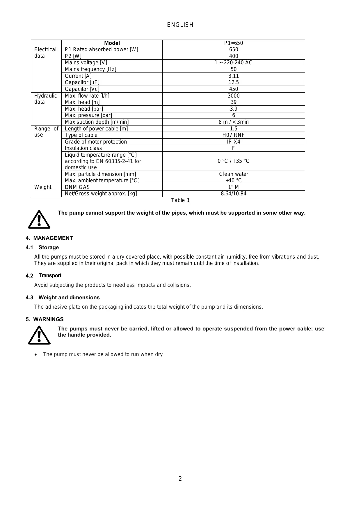
Table 3
| Model | P1=650 |
| Electrical data | P1 Rated absorbed power [W] | 650 |
| P2 [W] | 400 |
| Mains voltage [V] | 1 ~ 220-240 AC |
| Mains frequency [Hz] | 50 |
| Current [A] | 3.11 |
| Capacitor [μF] | 12.5 |
| Capacitor [Vc] | 450 |
| Hydraulic data | Max. flow rate [l/h] | 3000 |
| Max. head [m] | 39 |
| Max. head [bar] | 3.9 |
| Max. pressure [bar] | 6 |
| Max suction depth [m/min] | 8 m / < 3min |
| Range of use | Length of power cable [m] | 1.5 |
| Type of cable | H07 RNF |
| Grade of motor protection | IP X4 |
| Insulation class | F |
| Liquid temperature range [°C] according to EN 60335-2-41 for domestic use | 0 °C / +35 °C |
| Max. particle dimension [mm] | Clean water |
| Max. ambient temperature [°C] | +40 °C |
| Weight | DNM GAS | 1" M |
| Net/Gross weight approx. [kg] | 8.64/10.84 |

The pump cannot support the weight of the pipes, which must be supported in some other way.
4. MANAGEMENT
4.1 Storage
All the pumps must be stored in a dry covered place, with possible constant air humidity, free from vibrations and dust. They are supplied in their original pack in which they must remain until the time of installation.
4.2 Transport
Avoid subjecting the products to needless impacts and collisions.
4.3 Weight and dimensions
The adhesive plate on the packaging indicates the total weight of the pump and its dimensions.
5. WARNINGS

The pumps must never be carried, lifted or allowed to operate suspended from the power cable; use the handle provided.
The pump must never be allowed to run when dry
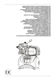
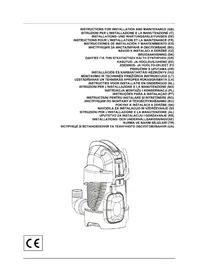
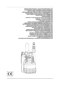
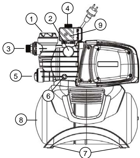
6. INSTALLATION
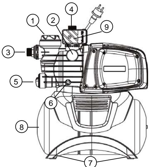
1 Pre-filter
2 Gauge
3 Swivel suction connection
4 Delivery connection
5 Integrated non-return valve
6 Drainage cap
7 Vibration-damping rubber feet
8 Tank 18 I
9 Flow switch
The pump must be installed in a place protected from unfavourable weather conditions, and with an environment temperature not higher than 40^ .
The pump is provided with vibration-damping rubber feet, but in the case of fixed installations it is possible to remove them and provide anchorage to the base (7).
Do not allow the pipes to transmit excessive forces to the pump inlets (3) and (4), to avoid creating deformations or breakages.
It is always good practice to place the pump as close as possible to the liquid to be pumped. The pump must be installed only in horizontal position.
The pipes must never have an internal diameter smaller than that of the pump inlets; on intake, the pump is provided with a filter (1) and a non-return valve (NRV) (5).
For suction depths of over four metres or with long horizontal stretches it is advisable to use an intake hose with a diameter larger than that of the intake aperture of the pump. To prevent the formation of air pockets, the intake hose must slope slightly upwards towards the pump. Fig.2
If the suction pipe is made of rubber or flexible material, always check that it is of the reinforced vacuum-resistant type to avoid shrinkage due to suction.
In case of a fixed installation, it is recommended to fit a closing valve on both the suction side and the delivery side. This allows closure of the line upstream and/or downstream from the pump, useful for service and cleaning operations or for periods in which the pump is not in use.
The pump has a rotating inlet to facilitate installation (3) and (4).
In the case of flexible pipes, if necessary, use a bend fig. 1 and the gardening kit composed of a PE pipe and a kit of couplings with lance. These are not supplied, but can be bought separately.
In the case of very small dirt, as well as the integrated filter (1), it is recommended to use a pump inlet filter fitted on the suction pipe.
- Do not subject the motor to excessive starts/hour; it is strongly recommended not to exceed 20 starts/hour.

The diameter of the suction pipe must be greater than or the same as the diameter of the pump inlet, see Table 3.
7. ELECTRICAL CONNECTION

Ensure that the mains voltage is the same as the value shown on the motor plate and that there is the possibility of making a good earth connection. Follow the indications on the technical data plate and in this manual, table 3. The length of the power cable on the pump limits the installation distance, if an extension is required, make sure that it is of the same type (e.g. H05 RN-F or H07 RN-F depending on the installation) see tab.
8. START-UP

Do not start the pump without having completely filled it with liquid, about 4 litres.
If the water supply is finished, take the plug out of the socket immediately and switch off the pump. Avoid dry running.
- Before starting, check that the pump is properly primed, filling it completely, with clean water, through the filling hole, after having removed the filling cap of the transparent filter (1), with your hands or with the appropriate tool provided. This ensures that the mechanical seal is well lubricated and that the pump immediately starts to work regularly. Dry operation causes irreparable damage to the mechanical seal.
- The filling cap must be screwed on accurately until it stops (1).
- Insert the plug of the power cable in a 220-240 V power socket. Attention! The pump motor will start immediately, the water will start to come out after a maximum time of 3 minutes, depending on the depth of the water level, in the well or cistern.
- The pump is automatically deactivated when the maximum pressure is reached. If, when using water, the pressure falls below the minimum value, the pump is activated automatically. See Tab.3.
- To switch off the pump completely, take the plug out of the power socket.

In case of problems with the priming, repeat the handling until all air in the suction is disappeared.
9. PRECAUTIONS
RISK OF FROST: when the pump remains inactive at a temperature lower than 0^ , it is necessary to ensure that there is no water residue which could freeze, causing cracks in the plastic parts. If the pump has been used with substances that tend to form a deposit, or with water containing chlorine, rinse it after use with a powerful jet of water in order to avoid the formation of deposits or encrustations which would reduce the characteristics of the pump.
10. MAINTENANCE AND CLEANING
In normal operation the pump does not require any type of maintenance. In any case, all repair and maintenance work must be carried out only after having disconnected the pump from the supply mains. When restarting the pump, ensure that it has been correctly reassembled, so as not to create a risk for persons and property.
10.1 Cleaning the suction filter
Fig.3
- Switch off the electric power supply to the pump.
- Drain the pump, opening the drainage cap (6), after having first closed the gate valves upstream (if present).
- Unscrew the cover of the filter chamber, with your hands or with the appropriate tool provided
- Extract the filter unit from the top
- Rinse the cup under running water and clean the filter with a soft brush.
- Reassemble the filter, performing the operations in inverse order.
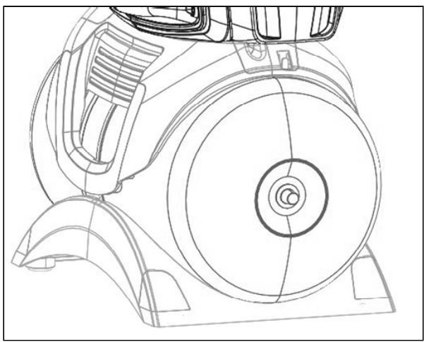
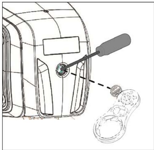
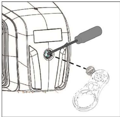
10.2 Cleaning the NRV
(Fig.4)
- Switch off the electric power supply to the pump.
- Remove the cap of the NRV (5) with the accessory provided.
- Remove the NRV check valve and clean it to remove any dirt.
- Assemble the parts, proceeding in inverse order to disassembly.
11. TROUBLESHOOTING

Before taking any troubleshooting action, disconnect the pump from the power supply (i.e. remove the plug from the socket). If there is any damage to the power cable or pump, any necessary repairs or replacements must be performed by the manufacturer or his authorized customer support service, or by an equally-qualified party, in order to prevent all risks.
| FAULT | CHECKS (possible cause) | REMEDY |
| 1. The motor does not start and makes no noise. | A. Check the electric connections.
B. Check that the motor is live.
C. Check the protection fuses.
D. Possible intervention of thermal protection | C. If they are burnt-out, change them.
D. Wait about 20 min until the motor cools.
Check and eliminate the cause.
N.B.: If the fault is repeated immediately this means that the motor is short circuiting. |
| 1. The motor does not start but makes noise. | A. Ensure that the mains voltage is the same as the value on the plate.
B. Look for possible blockages in the pump or motor.
C. Check that the shaft is not blocked.
D. Check the condition of the capacitor. | B. Remove the blockage
C. Use the tool provided to release the shaft.
D. Replace the capacitor |
| 3. The motor turns with difficulty. | A. Check the voltage which may be insufficient.
B. Check whether any moving parts are scraping against fixed parts. | B. Eliminate the cause of the scraping. |
| 4. The pump does not deliver. | A. The pump has not been primed correctly.
B. The diameter of the intake pipe is insufficient.
C. NRV non-return valve or filter clogged. | A. Fill the pump with water and prime it, taking care to let air out by unscrewing the vent cap.
B. Replace the pipe with one with a larger diameter.
C. Clean the filter and, if this is not sufficient, the NRV. |
| 5. The pump does not prime. | A. Suction pipe is taking in air..
B. The downward slope of the intake pipe favours the formation of air pockets. | A. Eliminate the phenomenon, checking that the connections and the suction pipe are airtight, and repeat the priming operation.
B. Correct the inclination of the intake pipe. |
| 6. The pump supplies insufficient flow. | A. The suction pipe is clogged.
B. The impeller is worn or blocked.
C. The diameter of the intake pipe is insufficient. | A. Clean the suction pipe..
B. Remove the obstructions or replace the worn parts.
C. Replace the pipe with one with a larger diameter. |
| 7. The pump is activated and deactivated too frequently | A. Damaged diaphragm of the expansion vessel
B. The expansion vessel pressure is too low | A. Have the diaphragm replaced by an authorised service technician.
B. Load the expansion vessel to 1.6 +-0.2 bar. |
| 8. The pump vibrates and operates noisily. | A. Check that the pump and the pipes are firmly anchored.
B. There is cavitation in the pump, that is the demand for water is higher than it is able to pump.
C. The pump is running above its plate characteristics. | A. Fix the loose parts more carefully.
B. Reduce the intake height or check for load losses.
C. It may be useful to limit the flow at delivery. |
FILLING THE EXPANSION VESSEL WITH AIR
The pressure in the expansion vessel must be approx. 1.6 + -0.2 bar. It is preloaded in the factory, so at the first start-up no operation is required.
To fill it with air you need an air pump or a device for inflating tyres with a pressure gauge (manometer).
- Unscrew the protective cover.
- Apply the air pump or the tyre inflating device to the valve of the boiler, pump air until the pressure gauge indicates about 1.6 + 0.2 bar.
- Screw the protective cover back on.
12. GUARANTEE

Any modification made without prior authorisation relieves the manufacturer of all responsibility. All the spare parts used in repairs must be authentic and all accessories must be authorised by the manufacturer, in order to ensure maximum safety of the machines and of the systems in which they may be installed.
This product is covered by a legal guarantee (in the European Community for 24 months from date of purchase) against all defects that can be assigned to manufacturing faults or to the material used.
The product under guarantee may, at discretion, either be replaced with one in perfect working order or replaced free of charge if the following conditions are observed:
- the product has been used correctly in compliance with the instructions and not attempt has been made to repair it by the buyer or by third parties.
- the product has been consigned to the outlet where it was purchased, attaching a document as proof of purchase (invoice or cash register receipt) and a brief description of the problem found.
The impeller and parts subject to wear are not covered by the guarantee. Intervention under guarantee does not extend the initial guarantee period in any way.
INDICE
- APPLICATIONI 6
- LIQUIDI POMPABILI 6
- DATI TECHNICI E LIMITAZIONI D'USO 6
- GESTIONE 7
3. TEXHNUECKN DAHHN I OPGAHNUEHEN 3A YIOTPEBA
3axpaHbAso HnpeXeHne: 220-240V, BIX KndeHT. Ta6ena C eJekTpuecknTe daHHI
- Празиелю Линяс c OTLOXeHO DeIcTBne (Bercn 220-240V):празирн CTOnHocTn (Ampepi)
- Tempepatya Ha cklaɪnpahe: -10°C +40°C
Tábniça 2
PnHaJIuHneTo Ha 3aMbpcBaHnIc MHOrMOaIKn pa3Mepn Ce npenOpbUba Da n3NoJI3BaTe,OCBeH BrpaJeHnIΦnITbp (1),ΦnJTbP Ha BxOda Ha NOMnata,MOHTnpaH Ha BCMyKaTeJIHaTa Tpb6a.
He npdnaaTe DnraTeNa HnpeKaJeHO MHO cTaptnpaHryac, cnlo ce npenopbYBa da He ce npebuwaBat 20 cTaptnpaHry/acy.

Диаметьрт Ha BCMykaTeJIHaTa Tp6a Tp86Ba Da 6bde NO-rolm nIpaBeH Ha Диаметьра Ha OTBopa Ha eNeKtpueeckata nomna, BIX Ta6nua 3.
7. EJIEKTPNUECKO CBbP3BAHE

Да ce npOBepn Дали 3axpaHbAIoTO HAnpeXeHne OTROBapr Ha N3NCKBaHTo Ha NOMnTa n da Ce OUeHN Bb3MOxKHOCTTa 3a NaIeJckHa 3a3EmKa Прдьрkaite ce KbM yka3aHnra, nocOueHn B Ta6enata C TEXHNueCKnTe DaHHn n B TOBA pkbOKoDcTBo, Ta6nua 3.
Дьлжината Ha 3axpaHbaun Ka6eI, HAnuyeH c nomnata, orpaHnuaBa pa3ctOraHneTo 3a MoHTaK, ako ce HaJara n3non3BaHe Ha yIbIxNteI, yBepTe ce, ye e OT cbuTn (Ha np.H05 RN-F uIn H07 RN-F B 3aBcIMoCT OT MOHTaKa) BIX Ta6I.3.
8. CTAPTIPAHE

He 3aedcTbaIte nomnata npedn da y haHbIhnte n3zIIO c TeuhoCT, pnp6bn3nteHNO 4 nItpn.
B cnuyaHa n3uepnbAhe Ha BODnHpecypc, He3a6abHNo n3KJIouyete UeNceJa, C KOeTo cnpaTe nomnata. N36yraIte paobotaHa cyxo.
- Преши рунckeанeto на помanta поверete далу помantaе e npabunho 3aЯта, кato пиctbnte Кьм
цялостното и habлвахсчstа вда спеса петз cneuaanHnry OTBOP, cneД kato cTe OTCTpaHnI Tanata 3a
Зарждане на позрачн� Фильтbp (1) рухно Или сьс спесианнгИ ИНСТРМЕNT, ДОставен Cmaшинata. Тoba
O3нача, ч мexанчното улътэне e doбpe сma3ano и помanta залоча Бedingara HopmaJIHATA cn
разota. Работа в cyх ржим boди до неюрравIMа NOВреда наMexahunHOTUyЛьтэн.
<|im_start|>assistant
- МатематICALS AND ANALYSIS OF THE MATHEMATICS AND ANALYSIS OF THE ANALYSIS OF THE MATHEMATICS AND ANALYSIS OF THE ANALYSIS OF THE MATHEMATICS AND ANALYSIS OF THE ANALYSIS OF THE MATHEMATICS AND ANALYSIS OF THE ANALYSIS OF THE MATHEMATICS AND ANALYSIS OF THE ANALYSIS OF THE MATHEMATICS AND ANALYSIS OF THE ANALYSIS OF THE MATHEMATICS AND ANALYSIS OF THE ANALYSIS OF THE MATHEMATICS AND ANALYSIS OF THE ANALYSIS OF THE MATHEMATICS
-
CnE TOBa, npo6KaTa 3a 3apeKdahe Tp8Ba Da ce 3aBne OTHOBO CTapaTeJIHO, DOKaTO ppeTaHe da Ce BbPtn (1).
-
BkIIOUeTe 7eHcEJa Ha 3axpaHbAunKa6eN KbM 3axpaHbAun KOHTaK T O 220-240V. BHMaHHe! DBrTaTeJrT Ha NOMnTa 7e Ce CtApTnPa He3a6abHo, BOaTa 7e 3aONuHE Da I3JIIN3a CneD MaKcIMyM 3 MInHyTN, KoETO 3ABNCN OT DblboOHnHa HA HNBOTO Ha BOaTA B KlaJeHeca INI B cIcTePnHaT.
- Пи доctиогену на мakсимално налгаге, понаразе DeakTNBupa abTomatuHo. Ako ce n3noJ3Ba Boda n haЯганeto сеzeп по мниманanto Haяганe, понаразе acTNBupa abTomatuHo. Bx. Ta6.3.
- 3a da cnpete nomnata OKOHaTeIHo, nKJIouhe Te IeNceJa Ha 3axpaHbaun Ka6eJ.

B cnuyaHa npo6JIemn CbC 3aJINBaHeTo npeDn NpCKaHe B DeIcTBne, NOBTOpe Te o6pa6OkaTa, DOKaTo n3ue3Ne BCNUKnA rT Bb3dUx pRn BCMyKBAHeTo.
9. ПЕДПАЗНМЕРКИ
ОПАСHОCT OT 3AMPb3BAHE: korato nomnata octaHe HeakTbHa npu TempepaTypa noD 0^ , e Heo6xOДmO da ce yBepnte, ye HЯMa OCTaTbU O T BODa, KOINTO 3aMpb3BaKn, MORaT da npedIN3BnKaT pKNaTHn B nIaCTMacOBnTe qactN. Ako nomnata e 6bJa n3NoI3BaHa C BeueCTBa, KOINTO ce yTaBAt IIn C XJOpnpaHa BODa, n3PnAKeHte cIeI yNtpe6a CbC cINHa cTpyr BOda, 3a Da He Ce dOnyche Obpa3yBaHe Ha yTaKn IIn OTLarAHn, KOINTO MORaT Da BnOlaat XapakTepnCTNKITE Ha nomnata.
FYLDNING AF EKSPANSIONSBEHOLDEREN MED LUFT
2. SIURBIMUI TINKAMI VANDENYS
Svarus, be kietu ir abrazyvini daleliu, chemiskai neutralus.
9. VOORZORGSGMAATREGELEN
Adequado
Nao adequado
3. DADOS TECNICOS E LIMITAÇÖNES DE USO
Hacoc He MoKet BbIePknBaTb Bec Tpy6, KOtOpbIe DOnJXhbl NODePknBaTbCnHaue.
4. 3KcπIyATALUN
4.1 CknaHpoBaHne
Bce HacocbI DOnJHbI cKnAaHnpOBaTbC B KpbITOM, CyXOM NOMEUeHN, NO BO3MOXHOCTn C NOCTOHHo BNaJHOCTbIO B03dyxa, 6e3 Bn6paun I nbIIN.HacocbI NOCTABNIOTCB INx 3aBOJCKo OPUNHaJIbHOJ yNAKOBKe, B KOtOpOH OHI DOnJHbI OCTaBaTbC BnIOTb Do MOMENTa INX MOHTaJa.
4.2 TpaHcnpoptnpoBka
PpeOxpanHe n3dEIny OT IInuHnX yIapOB INToJUkOB.
4.3 Bec npa3Mepbl
HakneiKa Ha ynakOBke yka3bIbaeT o6uN BEc 3JIeKToHaocOa n ero pa3Mepbl.
5. ПЕДУПЕЖDEHЯ

HacocbI HNKOrda He DoJXhbl nepeBO3ntbcra, NOHMATbCRA JINB BKNIOaTbCRA B NOBWeHOM COCTOAHNN, NcNoJIb3yra Ka6eJIb NITAHNA, NcNoJIb3yIte CneUaNbHyO pyKy.
Hacoc HNKoIa He IOnKeH pa60TaB BCxyH.
6. MOHTAX
1IpeBapnteHbIyΦnIbTp
2 MaHOMeTp
3 OpneHTnpyemoe coeHHeHne BCaCbBaHn
4 CoeHHHeHne noJaun
5 BCTpoEHnBn HeBO3BpaTHbN KlaNaH
6Пробka сиИВа
7 Pe3nHOBbIe Bn6poracIzne HOxKn
8 Pe3epByap 18 n.
9 PacxoDomep
3NeKtpoHaocOdoJKeH yCTaHaBJIbBaTcB MeCTe, 3aUHHeHHOM OT HEnOrOdbI n Tempepatyoi OkpykaioSei cpebl He bIwe 40^
Hacoc obopydoban BnBporaczIMM ONopamN, HO B cIyue HepepeHOChOYcTaHOKMOJHO CHaTb Ix N IpeDyCMOTpeTB KpenJIeHne K OOnOpHOMOCHOBaHIO (7).
I36eai Te nepeaun n36bItoUHOrO yCnJIn O Tpy6 K yCTbAm Hacoca (3) n (4), YTO6bI He CO3daBaTb DeΦopMauŋ IIN IIOJOMOK.
HeN3MeHNO XopoIIM npaBnIOM YBJIeTcYCTaHaBJIbBaTb Haoc KaKdKOCTH.
Hacoc DoJxhen 6bItb yctAHOBnHe INCKJIIOHTeJIbHO B TOpN3OHTaJIbHOM NOJIOXKeHm.
Tpy6bI HIKoIa He DoJIxHbI IMeTb BHyTpEHnI DnAmTeP MeHbIe, Yem yCTbI 3JIeKTpOHaCoca I BCacbIBaHnI HaOcO, HAcOC oBOpyOBOAH qJIbTpOM (1) n HeBO3BpaTHbIM KJIanaHOM (NRV) (5).
Дяглбны BCasibAHn, npeblyaIOSeYteIpe MeTpA, nIN npH NaJIHyN DInHHbIX TOpN3OHTaJIbHbIX OTpe3KOB peKOMeHdyETcN cNoJIb3OBAtB Tpy6y BCasIBAHn C dNaMeTpOM, bJbShm DnAmEtpa BCacbIBaIOUeO OTBepCTNЯ 3JIeKTPoHaCoca. Bo n36exKaHne O6pa3OBAHn BO3dUshbIX MeKOB BO BCacbIBaIOUeM Tpy6oPpOBoDE npedymOTpeT he6OJIbIoN IOdbem BCaslbAIOSeI Tpy6bI B CTOpOHy HAcoca. Pnc.2
Ecni Tpyba BcabBaHn BblIOJIHeHa n3 pezHHb IIN rI6KOro MaTePnAna, Bcerda npOBepaTe, YTO OHa yKpeJIeHoro Tnna, BbldepXnBaHOeBO Bakyum, YTO6bl N36EkaTb cyKeHn ppi BCacBbAHnn.
B cnyuae HepehochOn yctaHOBN peKomeHdyETcM OHTnPOBaT Klaanah 3aKpbITnKa Ka H CTOpOHe BCacbBAHnra, TaK n Ha HapnoH CTOpOHe. 3TO N03BOJnEe T3aKpbIbTa IINHIO nepeh HAcOCOM IINI NOcNe Hero, YTO Tpe6yETcR npi npoBeHeHH TeXOBcNoKBaHnRA OCHCTKN IIN B cNYuae HeNCNOJIb3OBAHnra HAcoca B TeUeHne OnpdeJeHnro nepoHa. Hacoc Ochaueh BpaauoUmCMBxODom IIN oBJeHnry yCTaHOBN. (3) n (4).
B cnyuae 7nnaHROB, ecnn Heo6xOdIMO, nCnoIb30BaTb KOJIeHO pnc.1 IN KOMPJIeKT caIOBOJcTB coCTOHT n3 7JNaHROB I3 N KOMPJIeKT C HAKOHeuHnKOM He NoCTaBnETCr, IN HYKHO NOKyNaTb OTDeJIbHO.
B npncytcbnn 3aqr3HeHn He60nbux pa3MepOB, peKOMeHyeTcN cNoJIb3OBAtB, NOMMO nHTerPnpOBaHHoro fIbtpa (1), BxOdHn OfIbTp HacOca, MOHTnpOBaHHbHa IaHaHr BCacbBaHna.
He noDBepraTe DnBraTeIb N36bIToHOMy KOJIuYeCTBy 3aNyCKOB/YacOB, peKOMeHNdyETcR He npEByTaTb 20 3aNyCKOB B Yac.

DnAmEtTp Tpy6bl BcacbIBaHn ydoJxeh 6bItb 6oJbwe nn paBhIM, Yem DnAmEtTp yctbY 3neKtpoHaocca, cm. Ta6nuy 3.
7. 3ЛЕКТРИСЕСКOE ПОДКЛЮЧЕНЕ

Поберпь, утоби habрженье сети щлковпунаян COOTBECTBOBaNo Hanрженью, уka3aHHOMу Ha 3aВODСКОТаБЛЧЕДВИГATEЛЯ, утоби быLOВЗМоЖно ПОИЗВECTИ HADJIEXKAUSEE COEДИHEHIE 3A3EMЛЕHEN. BылOLнайTe уka3ань, пивебeENьile Na TeXHnueckoТаБЛЧIKE n By pkoBoDcTBe B ta6лиц 3.
He BkIIOuayaIte Haoc He 3aONHINB ero IOnHOCbIg XnIDKoCTbI, OKOJIo 4 JInTPOB.
Ecnn nctouontc rnpablnueckn pecypc, HemeJeHNO OTCoeHNHTe BnIky, BbIKNIOuH Nacoc. IpeDoTbpaaTe paobTo 6e3 Bobl.
- Ipeed Naayamom Nyska npOBepbTe, yTo HAcOC NoJIHOCTbO 3aIpaBHeN BDOi, oBeCneuBaJ erO noHoe 3aONHeHne YnCToB BOIO, Upe3 CneuaJIbHOe OTBepCTne, NocNe CHaTna KpbUkN 3aIpaBKn IpO3paCHoro fInbTpA (1), pyKaMn INI pRi NOMOUs NODXODJeTO INHCTpymEHTa B KOMPNeKTe. DaHHa ONEpaUN RAJIyETcR ype3BvauH BaxHo JI XOPOSeO FyHKUHOHnpOBAHn HAcoCA. BaxHo TaKKe, YTo6bl MexAHueckoe yIIOTHHeHne 6bIJO XOPOSO CMA3aHO.
Функционироваим BCухуЮ Bedet K HeNoIpaBIMbIM NOBpeKdEHHaM MExaHnueckOTo yNlOTHeHЯ.
-
Побку заправки седует BHOь 3akpyTNь на мecTodo octaHOBk (1).
-
BCTaBtB BnIky Ka6eJy NiTaHnB B po3eTKy NiTaHnB 220-240 B. BhMaHHe! DBrIaTeNb HacOca HeMeDJIeHHo 3apa6Otaet, BOda NauchET BbIXoDInT b Cnyctra MaKcMym 3 MmHyTbI, YTO 3aBNCIT OT rIy6uHbI ypOBHr BObl B KOJIoDuce IJIu cIcTePhe.
- Послд дocнжehma МксmaJIbHOrO DAblEnHЯ HAcOC BbIKIouaETcA bTOMaTUnCeKn. EcIn npi nCIOJIb30BaHm BOdI DAblEnHne CnYCKaETcH NHeKe MHNImaJIbHOrO DAblEnHЯ, HAcOC aTOMaTUnCeKn BKJIouaETcR. CMOTpr Ta6.3.
5.Дя OkohyateJIbHOrO OTKIIOUeHnHaHoca OTcoEINHTe BnIKy Ka6eI pyntAHnY.

Пи Нашип пообLEM с наюненem, NOВТОпЕ опрацIH, NOKA BO3dYx Ha BCaCSbIbAHn He 6ydeT ydaJIeH.
9. ПЕДОCTОPOЖHOCTN
OPACHOCTb 3AMEP3AHNIA: KOrda Hacoc ocTaetcH He BkIIOueHHbIM npn TempeaType Hnke 0^ , Heo6xOdmo y6eINTbcra, YTO B HEM HET OCTaTKOB BOdbI, KOtOpbl E pRn 3amep3AHIN MOrY TnpBecTn K TpeuHAM PJIaCTNKOBbIX qactei.
Ecni Hacoc nCnoIb3OBAJcra C BeIeCTBaMn, KOtOpBie IMeHOT TeHdEHNIO K OTNoXeHNO IIN C XNOpInpOBaHHo BDOi, ONoIocHnte erO nOcne NcNoJIb3OBAHnA CNJbHO CTpye BObl, YTObI N36eKaTb φOpMnPoBaHnA OcaKa IIN OTNoXeHNI, KOtOpBie CHNXaOT 3KcNJyatauONHbIe XapakTePrcNTIKn HaCoCA.
10. TEXHnueCKOE O6CJIyXKBAHNE N YNCTKA
B HopmaIbHOM pa6ooyem pexKIme 3JleKtpoHaocO He hyxdaetcB KAKOM-JIn6o TexHnueckom o6cnyKnBaHHN. B JIObOM cnyae BCE pa6oTbI NO peMOHTy IN TexHnueckomy O6cnyKnBaHHIO DOJXHbI OcyIeCTBnA Tbcra NocJIe OTCoEINHeHn HaocOa OTcN 3JleKtpoNTaHHN. PpN 3aNyScke HacOca y6eIITecb, YTO OH bbl CO6paH n IO BcEM IpaBnAm, YTObI He Co3dAbTaONachOCTn DnI NIODeI INpeIMeTOB.
10.1 OuInctka qHJIbTpBaCacBbAHn
(Cxema 3)
- OBeCTOuHTb Haoc.
Cnntb BODy,OTKpbIB npo6ky cInBa (6), 3aKpbIB npeBapHTeJbHO 3acNoHKn nepei Hm (ecnn ImEOTc).
OTBnHTnte KpbIuKy KamepbI nJIbTpa, pykamNJIcneuaJIbHbIM INHCTpyMeHTOM B KOMJIeKTe.
BbInbTe uepe3 Bepx 6Jok Hacoca.
- Onolochnte ctaKaH IOd cTpye BODbl OCHNTte fNJIbTp pRn NOMOUI MRAKOH IeTKN.
BHObco6epnte ΦnJIbTp, BblIOJHNB onepaunn B o6paTHoI nocJeIOBaTeJIbHOCTN.
I3dJIe IIO rapaHTnMoKet 6bITb 3aMeHeHO Ha dpyroE bpaOoHc COCTOHHN
IINI 6ecnIaTHO OTpeMOHTnpoBaHO npi coBIOJeHm CneJeUOnx ycIobN:
INNEHÄLLSFÖRTECKNING
- ANVÄNDNINGSOMRÄDEN 133
- VÄTSKOR SOM KAN PUMPAS 133
- TEKNISKA DATA OCH ANVÄNDNINGSBEGRÄNSNINGAR 133
- HANTERING 134
- YHnKaTn 3aHaITo cactnx BMnKaHb DnHyHa Ha npot3i rOuHN, HactiHo peKOMeHdyEByc8 He nepeBnUyBaTu 20 3anyckIB/roDInHy.

Дiametpr Tpy6n BCMOKTyBaHHЯ NOBHHEN 6yTN 6iNbWM a6o DOpIBHOBaTH iameTpny nATpy6ka OTbopy eNeKtpoHaocCy, nVB. Ta6JIuIcI 3.
7. EJEKTPNueHHe NIDKJIIOUeHHN

IpekeHaTnca B ToM, 0o Hanpyra Mepej XINBHeHna BiNobiAe BkazaiH na nacnpTHi Ta6nUci DnHyha, a TAKOX nepeBipNTm MOKJInBicTB HadiHoro 3a3emJIeHH. DToPmByBaTnc Bka3IBOK, 3a3NaueHnx Ha 3aBOcBki Ta6nUci Ta B Ta6nUci 3 daHoro TexHCHOrO nociHnka.
IobxHa Ka6eHIO XnBJeHHa HAcocy 06mexy BIdcTaHb Ioro yCTaHOBKn; B pa3i Heo6xIDHOCTI BnKOpNCTaHH NIOOBxBya apeBipHTu, 06 BIn 6yB TORO Jx Camoro TtNy (Hanp., H05 RN-F a6o H07 RN-F b3anExHoCTi BiD yCTaHOBKn) dN.B. Ta6.3.
8. NOYATOK POBOTN

He BmKataHacoc Do Tnx nip,doKn BiH NobHicTIO He HAnOBHHTbcra pIDHOIO,pNp6JIn3HO 4Iitpi.
Y BnnpaKy BnuepnaHHa BOn cIiD HeaHb BnTgHyTu BnKy 3 Po3eTKu, IIOB BmKHyTu HAcOC. YHkaTu pO6To "BCyxy".
- Ipeed BMnKaHmpeBipntu, 06 hacoc 6yB 3aJInTH nAleKHM uHOM uHCTOIO BOHO uee3 BiIDNOiHN oTbip, nCJIg 3HrTTAaINBHOI npo6Kn npOnyckHoro fIpIbtpy (1); nepeBipky 3diChIOBaTI BpyHy a6o CneiaJbHIM IHcTpymENTOM, 0u HadaeTbcB KOMPJIeKti. L' onepaiz HAa3BnuaHOBaxJIbA dJa 6e3dOranHOI pObotn HAcoca, 06 3aBe3neHTu HaleXHe 3MaUyBaHH MexaHCHORO yUilbHeHH. Po6ota "BCuyx" npn3BODNTb DO He3BOpOTHO NOWKoJKeHH MexaHCHORO yUilbHeHH.
2.Писяцboro сид ретелно зakpyтпл заливни робку до унору (1).
YKPAIHcBA
- BCTaBtN BuIky Ka6eIIO XuBIIeHnB Po3ETKy MepeXi XuBIIeHn3 HAnpyroIO 220-240 B. YBara! DInByH hAcoca yBIMKHeTbCg HeraHOb, BOa NOChE NoDaBaTncs MaKcMym Ha npOra3i HAcTyHNx 3 XBUNH, IIO 3aJIeXHTb BiD rINbHH pIBH BODN B KOnOJa3i YN B pe3epByapi.
4.Пися досаяннmaМakcmaJIbHOrO TnCKу HAcOC BmIMKaetbCЯ abTomaTUnHO.ЯкIo npBnKOpNCTaHHI BODn TnCK 3HnKyETbcra HnKYe mIHimaJIbHOro pIBH,HaCOC aBtOMaTUnHO BMkAeTbcra.DnB.Ta6.3.
- 506 30BCIM BUMKHyTN HAcOC, Tpe6a BnTgTN BuNkY 3 po3ETKN KINBHeHNA.

Jkuo BnHKaToB npoblem i3 3aJIuBkoH, NOBTOBAtn npokaKy do Tnx nip, DOKn He 3NkHe nobITpr Ha BCMOKTyBaHHi.
9. 3ACTEPEXHII 3AXOДN
PNI3IK 3AMEP3AHHЯ:якшо hacoc 3aJIshaεTbCBy Hepoboy cTaHI npi TempepaTypi HnKYe 0°C, cIiD nepekoHaTncB TOMy, lo B HbOMY HEMAe 3aJIshky BOIN, lo pRn 3amep3aHHI MOKe IOJKOJNTN PNaCTMaCOBi YactHIn HAcOca.
Picn BkopncTahnHaococy dIaBdeHnpeoBN, kci CxnlbHi do HakonuYeTa BidKnadeh, aO nicna nepekaUbaHH XlnpobAoHO BODIO nOro cIiD npomntu NCTOBO DOIO; IJr npommbaHnckOpNCTaTcNc CnblHM cTpyMeHem BoNi, 06 3anobirTu TbopeHHo BiKnaDeH, 0o MoKyt b HeratNBHO BpInHytn Ha ekcnlyataui Hi xapaKTepnCTnKi Hacoccy.
10. Доглад ТАТEXHИЧЕ OБСЛУГОВBAHHЯ
Pn HopmaIbHnx yM0Bax ekCnIpyataui eJeKtpoHaoc He notpe6ye HiaKoro texHiyHOro o6cLyroBaHHa. B 6ydb-koMy pa3i BcPi pOBoTu 3 pEmOnTu Ta texHiCyHOro o6cLyroBaHHa CnID BnKOHyBaTu TINbKNicN BIDKnIOeHNHaHOCcy BiD Mepexi JxNBHeHHa. Ipeed TIm, k3HOBy yBIMKHyTu HAcoc NiCnA TexHiCyHOro o6cLyroBaHHa Ta peMOHTy, cIiD nepeBipTu, 0o Bin 3i6paHn HaneXHM uHOM, 0o6 He CTbOpTu Nbe3neuHy cnTyauio Dn oc6 ta MaHa.
10.1 Ynctka BCMOKtyBaJbHoro φiNbTpa
(Ma1.3)
- BiДКПИЧИТи hAcO BiД МepeXi eNeKTPuHOro XIIBJIeHHЯ.
- Cnpoxhntn Hacoc, BiDkPmbn Dnra zboro 3nBHy np6ky (6); nonepedno nepekpntn 3acInkn paHie ne liHii (aKtO MaioTbc).
Biikpyntn KpnuKy Kaemprn fInbtpy BpyHy a6o 3a Donomoro 0 CneiaIbHor o IHcTpymeHTy, 0n Hadaetbc8 B KOMJIeKTI.
BntTn3Bepx6Jokfipbtpy.
- Помптс Кнгку пд CTpymehem npotouhoI BODи Ta npocntuФ phlbtp 3a DonomorOIO M'akoI uITkn.
3HOBy BCTaHOBuTn 0JIbTp Ha Micue, BnKOHaBm Bci OINcaHi BnUe Dii B 3BOpOTbOMy Noprky.
10.2 YNCTka HnK
(Ma1.4)
BiiKJIIOHTN HAcOC BiD MepeXi eJeKTpUHOrO XINBJIeHHJ.
3nTn np6ky HIK (5) 3a donomoro cneiaIbHoro IHcTpymEnHa, 0HaAeTbCBA KOMPJIekTI.
3Hn HnoBopOn (3anipn) Klanah HIK Ta NOuchNTN NOrO.
- BnkoHaTm MONTaX y 3BOpOTbOmy npraKy.
11. NOUYK

Ipeed TmM, kP03nouHaTn noSyk HenoJaDok, Heo6XiDHO BiD'EdHATn HAcoc Bid dJxepen EneKtpnuHoro XNBLeHnra (BNTaRTH BNkky 3 po3eTK). JaKIO Ka6eNb JXNBLeHnra a6O HAcoc B 6yDb-kaI Ioro eNeKtpnuHi qacTnHi noXkoJKeHi, peMOHT Ta 3amHy NOBHeH 3diChOBaTu BNPObHK a6O yNoBHOBaXeHn Hm UeHTp TexHUnx Nocnyr, a6O TexHUnn CneuaIant 3 BIDNOBIDHO KBAiΦikaicIO, 10 do3BOJIe 3anobirn 6ydb-RAKOmy pN3NKy.
| HEPONJADOK TA | (Mожлivi prочи) | шлихи IX усуненя |
| 1. Двигун
Вмкаétбая
i He
ryde. | A. Пechевироти[elektpruchni 3'еданн.
B. Пechевироти поачу habрги на
Двигун.
C. Пechевироти захиси плавki
Залобіжник.
D. Можлво, сцрацюов телков
зашст. | C. 3amiiити, якто перогори.
D. 3aчекати 20 xвилин, соб двигун
Вухолонув. Вярав'tи ршиниу та
усунту и.
N.B.: NOВторецни_HEполадки чез
kopOTКИnomіхок уасу вka3уе на корOTke
Замканни двигуна. |
| 2. Двигун
Вмкаétбая
i He
ryde. | A. Пechевироти, соб habрuya в мереки
Вidноюдала 3a3начени на заюсыкii
пасострий Табочи.
B. Вярав'tи можлви三百mbанни та
Засmічесни насятca та двигуна.
C. Пechевироти, сцob вал не сьв
Замлкован.
D. Пechевироти.stan kohandecatopa. | B. UsyHTи 3abuBaHny ta 3acmiyuBaHny.
C. 3a дopomorою cneцiaльно
iHCTpymeHTy, сцо наdaeТбя B
kompltekti, bIDKpytNTs Kpiшky, a NOTIM
ВухуTKOу розлokувати вал.
D. 3amiiHTи kondehcatop. |
| HEPONADOK TА | (mожлви prочини) | шлaxиix усуненя |
| 3.МOTOP пацюс 3перебаям. | A. Перевироти, соб是可以 наругам морекиЖавлиени 6уна достатню.В. Перевироти наPreдmet Терту вишкрябүваань мік рухомимпа Фіковань чадиham. | B.УсунтуprочиPreчшипсPreту вишкрябүваань. |
| 4.Hacoc He podас Вody. | A. Haboc He 6by 3ajntnн HailexнimЧINOM.B.Нededстатни дiametр BCMOKtybaNBHOIТуб.C.ЗабиваняТа засmчыань НПК aboФільта. | A. HabobnHTn Hacoc BODIO, BVKOHATN3aJIbKU HailexHIM ChINOM, BInpuctNTn nobiTPR, BIKpyTbBShn cnyckHy pO6kY.B.ЗamihITn Tpy6b Na Tpy6b 3 bInbshmДiametrom.C.ПочstITNФільtp, aЯкsoц bOrOHeNoCTaTHBO- i HPK. |
| 5.Hacoc He 3aJIbBa€tsя. | A. BCMOKtyBaHnna Nobitpr chpe3BCMOKtyBaJbHy Trpy6b.B. HeratibHni Haxnil BCMOKtyBaJbHoIТу6bСпраз ec yTBOpEHnIO nobitrynxПробok. | A. UcyHTn PrO6bIeMy, NepebipuBshn repreMtchNICTb 3'EDHaNb Ta TpyboNPoviD BCMOKtyBaHnN, Notim NOBtropNTn onepaizio 3azinBaHNy.B.ВирравITN habрAm haxilnyBCMOKtyBaJbHoI Trpy6b. |
| 6.Hedocrtahni ровьп Podачи habocу. | A. BCMOKtyBaJbHa Trpy6a 3abitya abo3acmichena.B. Робоче кoleco сррацьовае abo3abloKOBaHe.C.Нededстатни дiametр BCMOKtyBaJbHOrTO Trpy6bOBPOBdy. | A. ПочstITN BCMOKtyBaJbHni Tpy6bOPIBd.B. UcyHTn 3abivbanhy Ta 3amihITn cspauZbOAniЧаTiHnC.C.ЗamihITn Tpy6bOPID Na Tpy6bOPIBd 3 bInbshmДiametrom. |
| 7.Hacoc BMikaecTbSri BVMkaecTbSri HabtoчTo. | A. Пошcodжета Мembrpaha po3ширpoBaJbHOrO 6auchka.B. Habto Nn3bKni pIBeHb TnCKyВpo3ширpoBaJbHOMy 6auchy. | A. 3amHa MEm6paHni 3 6oky uynOBHaxeHORO texhichHoro nepcoHany.B.ЗanOBHOBANHЯ рozshiroBaJbHOrO 6auchka Do Досягн徳 1,6 +0,2 6ap.DinB.Ta6.3. |
| 8.CsMbHa Bi6paizia habocu, storOhniшу mіd чak ров'tи. | A. Перевироти, соб是可以 haboc ta trpy6bОрвODи 6byl n 3akpirlleniHaNeXHMчINHom.B. Haboc пацюс 3 kavitaцievo, заити на BodуPrepeBniuzye Ioro notyKHiCTb podaqui.C. Haboc пацюс 3a pamkami Bka3aHnx na 3abodckiin naclonptnii Tablinuzdiданx. | A. 3akpirltn peTeIbHo ocIa6bleniЧаctHn.IB. 3meniHTn PIBeH BCMOKtyBaHnN abo nepebivrtti Na BiDCyTHiCtB BITOKy Habopy.C.Може БутNi copicshm obmexkitn habip Na podaqui. |
3AIOBHHTI NOBITPAM PO3UHPOBAJBH N BAYOK
B p03uipobalbHomy 6aay Tnck noBunen 6ytn Ha pibH ni pni6I. 1,6+-0,2 6ap. Ppi nepwomy ncy Hemae Heo6xidnocti y BnKohHaHi JaXIOcB doaTkoBnx dii, ockIbKn 3 a6pNI K BNPO6Hnka BiH NOCTABJcE7bc3 NonepeD him HakaYBaHHm. Iio6 3anOBHNt 6aok NObitpam, Heo6XiHO cOpncTaTnca NobitprHO NOMHO abo npicTpOem dny HakaYBaHHaHH 3 NOKa3HcKOM TnCKy (MaHometpom).
- Bīdūkpytɪn tɪn 3axiçhny kprùnkj
2.Пд'едати поитraynomу abo писрий дя начуваньшн do КлanaHy, начувати поитray do Tnx nip, покmaHometр He nokajke np6n.1,6 +-0,2 bar.
- 3HOBy 3aKpyTnTn 3axnchy KpnIky.
12.「PAHTI

Буд-як моифikaци, сн He 6ул nonepeHbO y3roJxehi 3 Bnpo6HnKOM, 3BilbHЯOTb Bnpo6HnKa BiD 6yIb-якoi BiINOBiJaNbHocTi. Bci 3anachi YactHHДЯ peMOHTy NOBHHI 6yTN opriHaJIbHMn YactINHAMn BiD Bnpo6HnKa npictpo, a Bci akcecyapn cIid y3roJNTN 3 Bnpo6HnKOM, sO6 rapaHTyBaTn MaksmaJIbHy 6e3neky ekcnnyatauii TORO oblaHaHHa Ta npictpoIB, Ha kI BOHN BCTaHOBIIIOJTObcr.
Dahm Bnpi6 NOKPNTM IOPNDHNOI RapaHTieO (Ha TepnTopiE BponecBkoR Oco3y Ha npot3i 24 McaizB 3 daTn KynibJI) BiDnHO CIX DeΦeKTIB, BKNJInKaHnx Baamn Bnpo6HnCTBa a6o DeΦeKTaMn BkOpNCtAnx MaTepiAINb.
BnpiHa rapaHtii 3a piueHnram Bnpo6nka nIpyae afo 3amHi ha iHsi, y BiDmiHOMy poohomy cTahi, abo 6e3koTuOBHOMy peMOHTy; npu CbOmy NOBHHI dOpumyBaTnca HAcTyHHi yMOBN:
- ekcnnyataqia Bnpo6y npobdunacBipHO, y BiDnOBiHocTi do HadaHnx IHCTpyKci, nokynea b afo Tpeti ocoBn He HaMarajncB iDpemOHTyBaTN Ioro BJIaChIMN CINAmN.
BnpiDIOCTABLeHn B nyHKT npOdaKy pa3OM 3 DOKymeHTaIHO, 0o NiITBepJxye Ioro KynIBnO (paxyHok a6o Yek), ta KOPOTKIM ONNCAHm BnYBHeNoI npOblemn.
Poboe Koneco Ta iHsi yactHH, 10 NiIyraIOb HOpMaIbHOMy cnpauBOAHHIO, He nokpmbaOTcra rapaHTieO. Oepaui 3 rapaTHiNHO oBcIyROBaHNN Hi B kOMy pa3i He npn3BOJrB Do noIOBKeHN NOaTKOBOro TepmiHy rapaTII.