SG7000i - Generator SCHEPPACH - Free user manual and instructions
Find the device manual for free SG7000i SCHEPPACH in PDF.

User questions about SG7000i SCHEPPACH
0 question about this device. Answer the ones you know or ask your own.
Ask a new question about this device
Download the instructions for your Generator in PDF format for free! Find your manual SG7000i - SCHEPPACH and take your electronic device back in hand. On this page are published all the documents necessary for the use of your device. SG7000i by SCHEPPACH.
USER MANUAL SG7000i SCHEPPACH
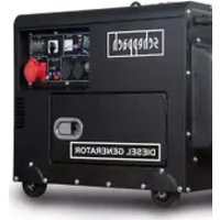
natural_image
Line drawing of a portable electricity generator with control panel and buttons (no text or symbols)
Made in P.R.C.


SG7000i
GB Inverter generator | Translation of the original instructions 22
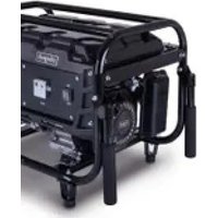
natural_image
Technical line drawing of a car's front wheel and side panel, with no visible text or symbols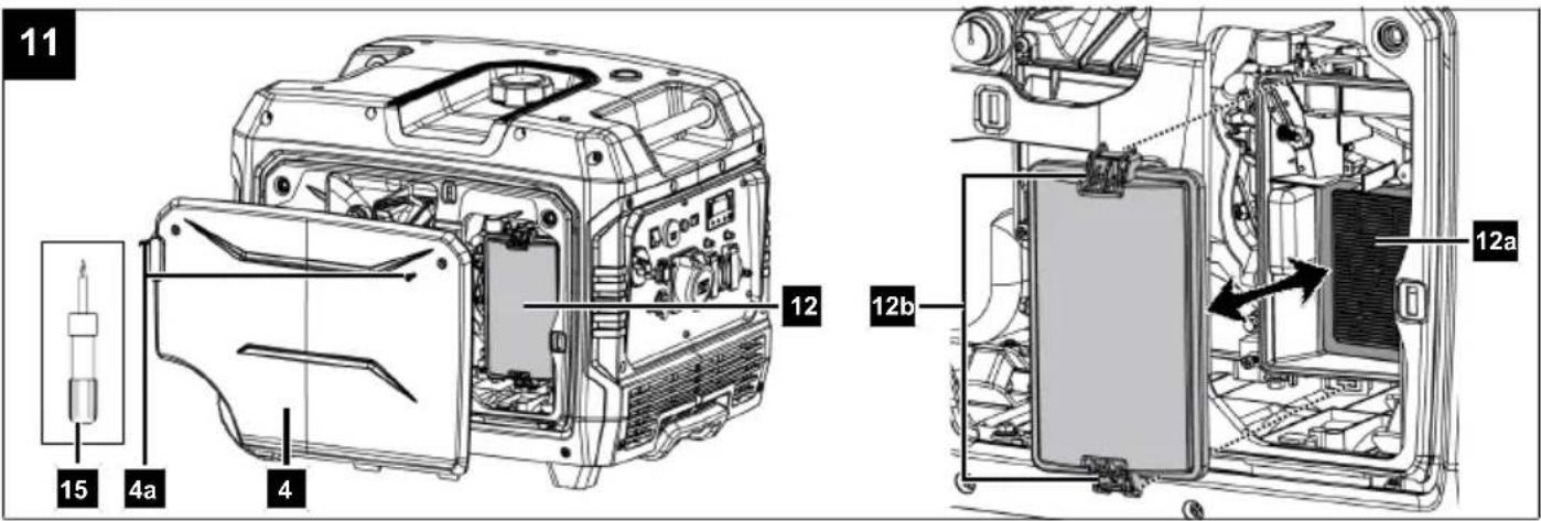
Inhaltsverzeichnis
Günzburger Straße 69
D-89335 Ichenhausen
Hinweis:
Günzburger Straße 69
D-89335 Ichenhausen
Division Manager Product Center

Andreas Pecher
Head of Project Management
Garantiebedingungen
Revisionsdatum 26.11.2021
1 Introduction ...... 23
2 Proper use.... 23
3 Product description (Fig. 1-13)....23
4 Scope of delivery (Fig. 2) 24
5 Unpacking 24
6 Technical data....24
7 Safety instructions.... 24
8 Before commissioning.... 27
9 Operation 29
10 Cleaning and maintenance 30
11 Storage and transport 32
12 Repair and ordering spare parts 33
13 Disposal and recycling 34
14 Troubleshooting 35
15 EU Declaration of Conformity.... 35
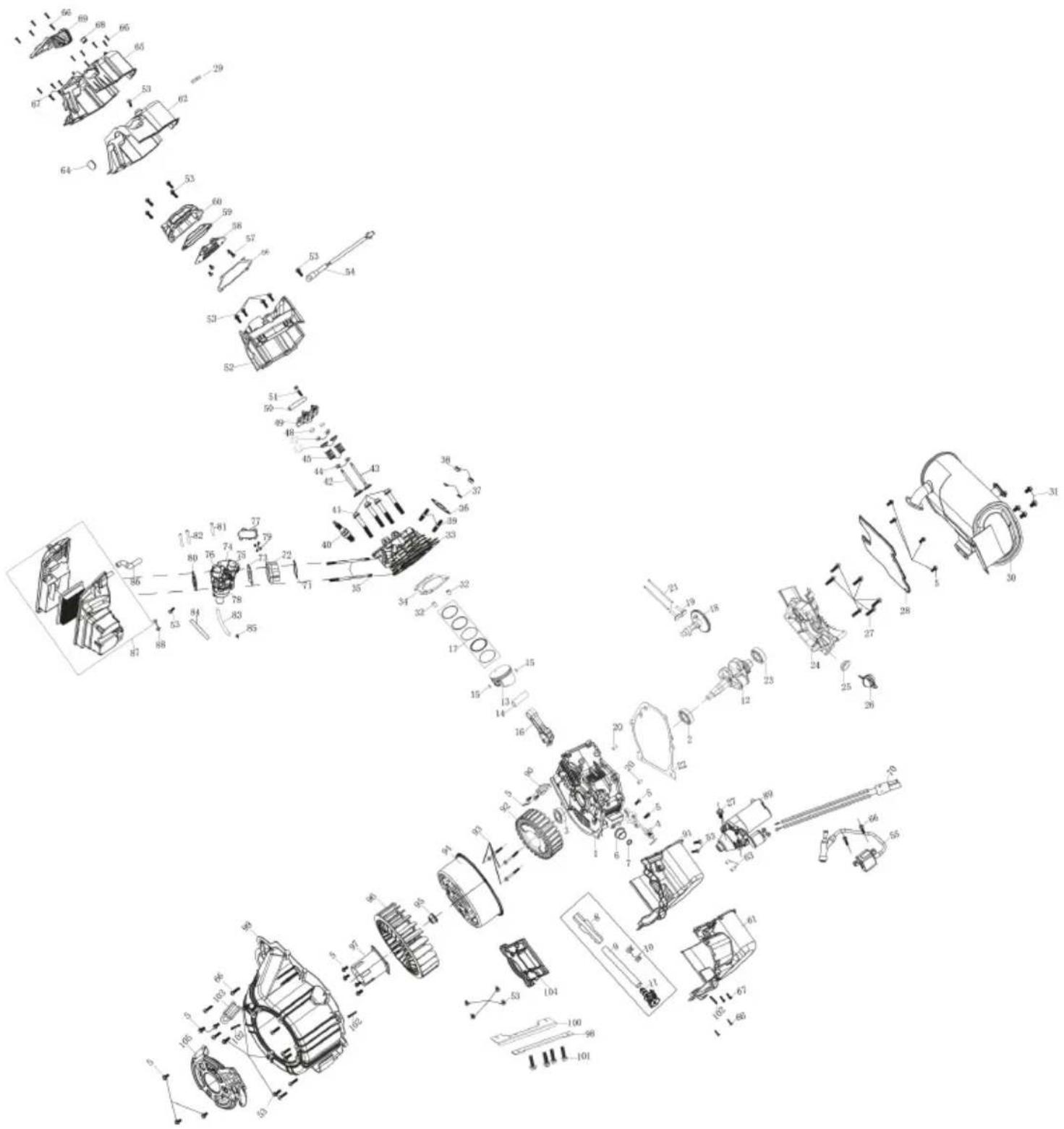
16 Exploded view.... 376
Explanation of the symbols on the product
Symbols are used in this manual to draw your attention to potential hazards. The safety symbols and the accompanying explanations must be fully understood. The warnings themselves will not rectify a hazard and cannot replace proper accident prevention measures.
| Attention! Failure to observe the safety signs and warning information affixed to the product and failure to observe the safety and operating manual can result in serious injury or even death. | |
| Before commissioning, read and observe the operating manual and safety instructions! | |
| Before commissioning, read and observe the operating manual and safety instructions! | |
| Wear hearing protection. | |
| Wear protective gloves! | |
| Do not expose the product to rain. | |
| Naked flames or smoking near the device is strictly prohibited! | |
| Warning against electrical voltage. |
| Tank contents | |
| Engine oil | |
| Warning - Hot surfaces! | |
| Make sure that other persons maintain a sufficient safety distance. Keep uninvolved persons away from the product. | |
| Before carrying out any cleaning or maintenance work, switch off the engine and remove the spark plug connector from the spark plug. | |
| Important. The exhaust gases are toxic. Do not operate the engine in areas that are not ventilated. | |
| Important. The exhaust gases are toxic. Do not operate the engine in areas that are not ventilated. | |
| Attention flammable substances. Fire, naked flames and smoking prohibited. | |
| Sparks are produced when the engine is started. These can ignite nearby flammable gases. | |
| Important. Always switch off the engine before refuelling. Do not refill during operation. | |
| Checking the oil level | |
| Guaranteed sound power level of the product. | |
| The product complies with the applicable European directives. | |
| The product complies with the applicable Serbian directives. |
Explanation of the signal words in the operating manual
| ! DANGER |
| Signal word to indicate an imminently hazardous situation which, if not avoided, will result in death or serious injury. |

WARNING
Signal word to indicate a potentially hazardous situation which, if not avoided, could result in death or serious injury.

CAUTION
Signal word to indicate a potentially hazardous situation which, if not avoided, could result in minor or moderate injury.
ATTENTION
Signal word to indicate a potentially hazardous situation which, if not avoided, could result in product or property damage.
1 Introduction
Manufacturer:
Scheppach GmbH
Günzburger Straße 69
D-89335 Ichenhausen
Note:
In accordance with the applicable product liability laws, the manufacturer of this product assumes no liability for damage to the product or caused by the product arising from:
- Improper handling
- Failure to comply with the operating manual
• Repairs carried out by third parties, unauthorised specialists
• Installing and replacing non-original spare parts - Improper use
- Failures of the electrical system due to failure to observe the national electrical requirements and regulations.
Note:
The operating manual is part of the product and contain important information for safe, proper and economical operation. Please also observe the applicable national regulations. Read all operating and safety instructions carefully before use and only use the product as described. Keep the manual and pass it on when you give the product to someone else.
2 Proper use
The power generator is suitable for Products that are intended to operate on a 230 V AC voltage source. With household devices and electronic products, please check the suitability according to the respective manufacturer's specifications.
The product may only be used in the intended manner. Any use beyond this is improper. The user, not the manufacturer, is responsible for damages or injuries of any type resulting from this.
An element of the intended use is also the observance of the safety instructions, as well as the assembly instructions and operating information in the operating manual.
Persons who operate and maintain the product must be familiar with the manual and must be informed about potential dangers.
The liability of the manufacturer and resulting damages are excluded in the event of modifications of the product.
The product may only be operated with original parts and original accessories from the manufacturer.
The safety, operating and maintenance specifications of the manufacturer, as well as the dimensions specified in the technical data, must be observed.
Please note that our products were not designed with the intention of use for commercial or industrial purposes. We assume no guarantee if the product is used in commercial or industrial applications, or for equivalent work.
3 Product description (Fig. 1-13)
- Fuel tank
1a. Fuel filler cap
1b. Fuel filter insert
1c. Sight glass - Transport handle
- Control panel
3a. Fuel valve
3b. Main switch
3c. On/off switch
3d. "RESET" button
3e. Energy-saving switch (ECO)
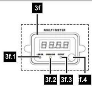
3f. Display
3f.1. Oil warning indicator (Low Oil)
3f.2. Overload indicator (Overload)
3f.3. Operating indicator (Output)
3f.4. Display button
3g. Fuse (230 V socket 16 A)
3h. Earthing screw
3i. 230 V \~ socket (16 A)
3j. 230 V \~ socket (32 A)
3k. 12 V DC connection
3l. Fuse (12 V socket)
3m. USB port - Cover
4a. Screw - Wheels
- Handle
- Pull starter
- Engine cover
8a. Screw - Spark plug
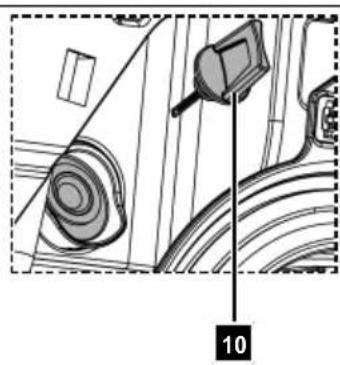
9a. Spark plug connector - Oil dipstick
10a. Oil drain hose
10b. Oil drain plug - Battery
11a. Battery bracket
11b. Battery connection cable
11c. Engine connection cable - Air filter cover
12a. Air filter
12b. Clamping lever - Funnel
- Installation spanner
- Phillips screwdriver
4 Scope of delivery (Fig. 2)
Item QuantityDesignation
-
1 x Funnel
-
1 x Installation spanner
-
1 x Phillips screwdriver
1 x Inverter generator
1 x Operating manual
5 Unpacking

WARNING
The product and the packaging material are not children's toys!
Do not let children play with plastic bags, films or small parts! There is a danger of choking or suffocating!
- Open the packaging and carefully remove the product.
- Remove the packaging material, as well as the packaging and transport safety devices (if present).
- Check whether the scope of delivery is complete.
- Check the product and accessory parts for transport damage. Immediately report any damage to the transport company that delivered the Product. Later claims will not be recognised.
- If possible, keep the packaging until the expiry of the warranty period.
- Familiarise yourself with the product by means of the operating manual before using for the first time.
- With accessories as well as wearing parts and replacement parts use only original parts. Spare parts can be obtained from your specialist dealer.
- When ordering please provide our article number as well as type and year of manufacture for the product.
6 Technical data
| Power generator Digital inverter | |
| Protection category IP23M | |
| Continuous output power P_n (COP) (230 V) (S1*) | 6 kW |
| Max. power P_max (230 V) (S2** 5min) | 6.2 kW |
| Rated voltage U_n | 2 x 230 V (16A)~1 x 230 V (32A)~1 x 12 V2 x 5 V |
| Rated current I_n 230V~ 26 A | |
| Rated current I_n USB 3.1 A | |
| Rated current I_n 12V 8 A | |
| Frequency F_n | 50 Hz |
| Performance class | G1 |
| Active power factor φ | 1 |
| Quality class | A |
| Type of engine | 4-stroke, 1 cylinder, air-cooled |
| Displacement | 298 cm ^3 |
| Rated engine power | 6.8 kW (9.2 PS) |
| Fuel | Super E10 petrol |
| Tank contents | 15 l |
| Engine oil type | 10W30 |
| Oil volume (approx.) | 650 ml |
| Automatic oil cut-off | Yes |
| Consumption at full load | 3.75 l/h |
| CO2 output | 820 g/kWh |
| Temperature Tmax | 40°C |
| Max. installation altitude (above sea level) | 1000 m |
| Spark plug | F7RTC |
| Weight | 60 kg |
| Battery type | Lead acid |
| Battery capacity | 6.5Ah |
Subject to technical changes!
\*Operating mode S1 (continuous operation)
The product can be operated continuously with the specified power.
\*\*Operating mode S2 (short-term operation)
The product may only be operated at the specified power for a brief time (5 min.).

WARNING
Noise can have serious effects on your health. If the machine noise exceeds 85 dB, please wear suitable hearing protection for you and persons in the vicinity.
Information about the noise level measured in accordance with applicable standards (EN ISO 3744:1995, ISO 8528-10:1998):
| Sound pressure level L_pA | 74.06 dB |
| Measured sound power level L_wA | 94.1 dB |
| Guaranteed sound power level L_wA | 96 dB |
| Measurement uncertainty K_pA | 0.83 dB |
7 Safety instructions
Keep all safety information and instructions for future reference!

WARNING
Read all safety warnings, instructions, illustrations and specifications provided with this product.
Failure to observe the following instructions can result in serious injuries.

WARNING
Before you start working with the product, familiarise yourself well with all the control parts.
– Practice using the product and have an experienced user or specialist explain its function, how it works and the techniques involved.
- Ensure that the product can be stopped immediately in the event of an emergency.
- Improper use may cause severe injuries.
- In the event of an accident or a fault during operation, switch the product off immediately. Treat injuries properly or consult a doctor.
Who is not permitted to use the product:
- Children and other people who do are not familiar with the usage instructions (local stipulations may specify a minimum age for users).
• People under the influence of alcohol, drugs and medication, as well as those who are tired or ill.
7.1 General safety instructions
ATTENTION
Attention!
When using products, several safety warnings must be observed to prevent injuries and damage. For this reason, please carefully read this operating manual/safety instructions. If you hand the product over to another person, please hand over this operating manual/safety instructions as well. We accept no liability for accidents or damage that occur due to a failure to observe this manual and the safety instructions.
• Children must be protected by ensuring that they stay a safe distance away from the generator.
- Fuel is combustible and highly flammable. Do fuel the unit during operation. Do not fuel the unit when someone is smoking or near open flames. Do not spill any fuel.
- Some parts of the reciprocating internal combustion engine are hot and may cause burns. The warnings on the power generator must be observed.

DANGER
Danger of poisoning
Exhaust gases, fuel and lubricants are poisonous, exhaust gases may not be inhaled.
ATTENTION
Risk of fire
Fuel and fuel vapours are highly flammable or explosive.
- Engine exhaust gases are toxic. The power generator must not be operated in unventilated rooms. If the power generator is to be operated in well-ventilated rooms, the exhaust gases must be discharged directly outside via an exhaust gas hose. Additional requirements for protection against fire and explosion must also be observed. Toxic exhaust gases can also es-
cape when operating an exhaust hose. Because of the risk of fire, the exhaust hose must never be directed at flammable materials.
- Power generating units should only be used up to their rated power under the rated ambient conditions. If the power generating unit is used in conditions that do not comply with the reference conditions according to ISO 8528-8:2016, 7.1, and if the cooling of the engine or generator is impaired, e.g. as a result of operation in restricted areas, a reduction in power is required.
- It is prohibited to make any modifications to the power generator.
- The manufacturer's preset speed must not be changed. Power generator or connected devices may be damaged.
- Never operate the power generator in rooms with highly flammable substances.
ATTENTION
Hot surfaces!
Danger of burns, do not touch exhaust system and drive unit.
ATTENTION
Wear hearing protection!
Use suitable hearing protection when you are near the device.
- Do not touch any mechanically moving or hot parts. Do not remove any protective covers.
- Only original parts may be used for maintenance and accessories.
• Repair and adjustment work may only be carried out by authorised specialist personnel. - Protect yourself from electrical hazards.
- Never touch the power generator with wet hands.
- Only use approved and appropriately identified extension cables for use outdoors (H07RN).
- Never operate the power generator during rain or snowfall.
• Always stop the engine when transporting and refueling. - Do not empty the tank near open light, fire or sparks. Smoking prohibited!
- Do not use the power generator in a thunderstorm - risk of lightning strike!
- Provide a secure, level place for the power generator. Turning and tilting or changing location during operation are forbidden.
- Place the power generator at least 1 m away from walls or connected devices.
- Values specified in the technical data under sound power level (LwA) and sound pressure level (LpA) represent emission levels and are not necessarily safe working levels. Since there is a correlation between emission and exposure levels, it cannot be reliably used to determine any additional precautionary measures that may be required. Factors influencing the current exposure level of the worker include the char-
acteristics of the workspace, other noise sources, airborne noise, etc., such as the number of machines and other adjacent processes and the length of time an operator is exposed to the noise. The permitted exposure level may also vary from country to country. Nevertheless, this information will enable the operator of the machine to make a better assessment of the risks and hazards. If necessary, acoustical measurements should be taken after installation to determine the sound pressure level.
- Observe the electrical safety regulations applicable to the place where the power generator is used.
7.2 Electrical safety
- Prior to use, the generator and its electrical equipment (including lines and plug connectors) should be checked to ensure that there are no defects.
- The power generating unit must not be connected to another power source such as the power supply of energy supply companies. In special cases where a reserve connection to existing electrical systems is provided, this must only be carried out by a qualified electrician who will take into account the differences between the operated equipment using the public mains and operation of the power generating unit.
The following differences between grid and power generation operations must be taken into account:
- Earthing and grid configuration:
The earthing and protective measures of the power generator may differ from those of the public grid and must be adapted accordingly. - Short-circuit power:
The short-circuit power of the generator is lower. Circuit breakers may trip with a delay or not at all.
• Voltage and frequency:
In generator operation, voltage and frequency may fluctuate depending on the load. - Feed-back:
Feeding into the public power grid is not permitted and must be prevented by means of suitable switchover devices. - Parallel operation:
Parallel operation with other power sources is only permitted with suitable synchronisation. - Load capacity:
High starting currents can lead to voltage drops.
The connection may only be made with suitable protective and monitoring devices. Improper connection may result in property damage or danger to life.
- Protection against electric shocks depends on the circuit breakers which are matched precisely to the power generating unit. If a circuit breaker must be replaced, this should be done using a circuit breaker with the same rating and performance characteristics.
- Due to high mechanical loads, only durable rubber hose lines (per IEC 60245-4) or equivalent equipment should be used.
- If extension leads or mobile distribution networks are used, the resistance value must not exceed 1.5 . As a guideline value, the total length of lines for a cross-
section of 1.5 mm ^2 should not exceed 60 m, and for a cross-section of 2.5 mm ^2 , 100 m should not be exceeded.

WARNING
Comply with the electrical safety regulations applicable to the place where the power generators are used.

WARNING
Consider the requirements and precautionary measures in case of re-supply of a system by power generators depending on the protective measures of this system and the applicable directives.
7.3 Handling fuel
ATTENTION
Use only E10 unleaded petrol as fuel.

DANGER
Danger to life!
Fuel is toxic and highly flammable.
- Only store fuel in containers (canisters) designed for this purpose.
- The tank caps must always be properly screwed on and tightened.
- For safety reasons, the fuel tanks and other fuel caps must be replaced if damaged.
- Keep fuel away from sparks, open flames, permanent flames, heat sources and other sources of ignition. Do not smoke!
- Refuel outdoors only and do not smoke while refuelling.
- Before refuelling, switch off the combustion engine and let it cool down.
- Fuel must be filled before starting the engine. While the engine is running or immediately after switching off the product, do not open the fuel filler cap or add fuel.
- Open the fuel cap carefully and slowly. Wait for the pressure to equalise and only then remove the fuel filler cap completely.
- Use a suitable funnel or filler pipe for refuelling so that no fuel can spill onto the combustion engine and housing.
Do not overfill the fuel tank!
- To leave room for the fuel to expand, never fill the fuel tank beyond the lower edge of the filling nozzle. Observe additional information in the combustion engine user manual.
-
If fuel has overflowed, do not start the combustion engine until the area contaminated with fuel has been cleaned. Avoid starting the engine until the fuel vapours have evaporated (wipe dry).
• Always wipe up spilled fuel immediately.
• If fuel has got on clothing, it must be changed. -
The tank cover must be properly screwed on and tightened after each refuelling operation. The product must not be put into operation without the original tank cover screwed on.
- For safety reasons, check fuel line, fuel tank, fuel cap and connections regularly for damage, ageing (brittleness), tight fit and leaks and replace if necessary.
- Only empty the tank outdoors.
- Never use beverage bottles or similar to dispose of or store operating materials, such as fuel. People, especially children, could be tempted to drink from it.
- Never store the product with fuel in the tank inside a building. Any fuel vapours produced can come into contact with naked flames or sparks and ignite.
- Do not place the product and fuel tank near heaters, radiant heaters, welding machines or other sources of heat.

DANGER
Risk of explosion!
If a defect is detected on the tank, the tank cover or on fuel-carrying parts (fuel lines) during operation, the combustion engine must be switched off immediately.
Then consult a specialist dealer.
7.4 Battery safety
• To avoid spark formation due to a short circuit, always disconnect the negative cable (-) from the battery first and reconnect it last.
- Never smoke during work on the battery. Always keep sparks, naked flames and other heat sources away from the battery.
- Special care must be taken when using jumper cables. Follow relevant instructions to avoid damage to the device (in particular, do not operate the starter for more than 10 seconds).
- Never open the battery and do not drop it.
• Always charge the battery in a closed room with good ventilation, dry and protected against the weather.
- Do not short-circuit battery connections.
- Deformed or defective (leaking) batteries must not be used and must be replaced and disposed of in an environmentally friendly manner. Observe the country-specific regulations.
- If the batteries are defective, liquid may leak out. Avoid contact! In case of accidental contact, rinse with water. If the liquid gets into your eyes, seek additional medical attention. Leaking battery fluid can cause skin irritation, burns and chemical burns.
- Regularly visually inspect the connection cables on the battery for damage. Have damaged cables replaced by a specialist.
- Never bypass the fuses. Never use a fuse with a rating other than the prescribed rating (amperes).
7.5 Additional safety instructions
ATTENTION
The power generator must not be connected to the mains supply as a domestic emergency power supply. It can cause damage to the power generator or other electrical devices.
- Never start or operate the product in an enclosed area. The exhaust gases are dangerous because they contain the odourless and deadly gas carbon monoxide. Operate the product only in a well-ventilated outdoor area.
Residual risks
The product has been built according to state-of-the-art and the recognised technical safety rules. However, individual residual risks can arise during operation.
• Health hazard due to electrical power, with the use of improper electrical connection cables.
• Furthermore, despite all precautions having been met, some non-obvious residual risks may still remain.
- Residual risks can be minimised if the "Safety Instructions" and the "Intended Use" together with the operating instructions as a whole are observed.
- Prevent the product being unintentionally started up.
- Keep your hands away from the working area when the product is in operation.
- Comply with the stipulated maintenance and safety instructions in the operating instructions.

WARNING
This power tool generates an electromagnetic field during operation. This field can impair active or passive medical implants under certain circumstances. In order to prevent the risk of serious or deadly injuries, we recommend that persons with medical implants consult with their physician and the manufacturer of the medical implant prior to operating the power tool.
8 Before commissioning
Electrical safety
Prior to use, the power generator and its electrical equipment (including lines and plug connectors) should be checked to ensure that there are no defects.
Never connect the power generator to the mains (socket). The power lines to the consumer must be kept as short as possible.

WARNING
Health hazard!
Inhalation of fuel / lubricating oil vapours and exhaust gases can cause serious damage to health, unconsciousness and in extreme cases death.
- Do not breathe fuel / lubricating oil vapours and exhaust gases.
- Operate the product outdoors only.
ATTENTION
Product damage!
If the product is operated without or with too little engine oil, this can lead to product damage.
- Fill with fuel and oil before starting the machine. The product is delivered without engine oil.
ATTENTION
Environmental damage!
Spilled oil can pollute the environment permanently. The liquid is highly toxic and can quickly lead to water pollution.
- Fill/empty oil only on level, paved surfaces.
- Use a filling nozzle or funnel.
– Collect drained oil in a suitable container. - Wipe up spilled oil carefully immediately and dispose of the cloth according to local regulations.
– Dispose of oil as per local regulations.
Check before operation
- Check all sides of the engine for oil or fuel leaks.
- Check the engine oil level.
- Check the fuel level – the fuel tank should be at least half-full.
- Check the condition of the air filter.
- Check the condition of the fuel lines.
- Look for signs of damage.
- Check that all protective covers are in place and all screws, nuts and bolts are tightened.
- Ensure that the product is sufficiently ventilated.
- Make sure that the spark plug connector is attached to the spark plug.
- Remove any consumer that may be connected.
Tool required:
- Funnel (13)
• Phillips screwdriver (15) - Socket spanner, size 8 mm*
- Funnel*
- Rag/cloth*
* = may not be included in the scope of delivery!
8.1 Earthing screw (3h) (Fig. 3)
ATTENTION
Electric shock!
- Do not use bare wires for earthing.
– Product must be safely earthed.
Earthing the housing is necessary to discharge static charging. To do this, connect a cable on one side to the earthing screw (3h) of the power generator and on the other side to an external earth (e.g. earth rod).
- Earthing regulations may vary depending on the country. Contact a local electrician to verify compliance with regional regulations.
8.2 Topping up oil (Fig. 4)
ATTENTION
The product is delivered without engine oil. Therefore, ensure that you add oil before starting it up. Use SAE 10W-30 oil.
Check the oil level regularly before commissioning. An oil level that is too low can damage the motor.
The oil warning system protects the product from damage caused by an oil level that is too low.
Before the minimum level is reached, the oil warning indicator (3f.1.) lights up and the system automatically switches off the engine.
- Place the product on a level, even surface.
- Remove the two screws (8a) from the engine cover (8). Use a Phillips screwdriver (15).
- Unscrew the oil dipstick (10).
- Use a funnel (13) to top up the engine oil. Note the max. filling capacity of 650 ml. Carefully fill the oil up to the lower edge of the filling port.
- Wipe the oil dipstick (10) with a clean, lint-free cloth.
- Re-insert the oil dipstick (10) without screwing the oil dipstick tight again.
- Pull the oil dipstick (10) out and read the oil level in the horizontal position. The oil level must be between L (low) and H (high) on the oil dipstick (10).
- If the oil level is too low, repeat the process.
- Then screw the oil dipstick (10) in again.
- Fit the engine cover (8) using the two screws (8a). Use a Phillips screwdriver (15).
8.3 Connecting the battery connection cable (11b) (Fig. 5)
- Remove the two screws (8a) from the cover (8). Use a Phillips screwdriver (15).
- Remove the battery bracket (11a). Use a 8 mm open-ended spanner.
- Remove the cover cap from the battery connection cable (11b).
- Connect the battery connection cable (11b) to the engine connection cable (11c).
- Insert the battery (11) into the battery compartment.
- Fit the battery bracket (11a). Use a 8 mm open-ended spanner.
- Fit the engine cover (8) using the two screws (8a). Use a Phillips screwdriver (15).
8.4 Filling in fuel (Fig. 6)
DANGER
Risk of fire and explosion!
When filling, fuel may ignite and even explode. This can lead to severe burns or death.
- Switch off the engine and let it cool down.
- Keep heat, flames and sparks away.
-
Only fill up with fuel outdoors.
-
Wear protective gloves.
- Avoid contact with skin and eyes.
- Start the product at a distance of at least 3 m from the fuel filling point.
- Watch out for leaks. If fuel is leaking, do not start the engine.
ATTENTION
The product is delivered without fuel. It is therefore essential to fill with fuel before commissioning. Use Super E10 petrol for this.
- Screw the tank cover (1a) on. The fuel filler cap (1a) is connected to an anti-loss device in the fuel tank (1) and thus cannot fall off.
- Use a funnel* to fill a maximum of 15 l of E10 unleaded petrol into the fuel tank (1).
- Ensure that the fuel tank (1) is not overfilled and that no fuel is spilled. Always use a fuel filter insert (1b). Clean up spilled fuel immediately and wait until the fuel vapours have evaporated (wipe dry).
- Check the sight glass (1c) while filling in the fuel. The level must be between E (empty) and F (full). If the level falls below E, fill the fuel tank (1).
- Retighten the fuel filler cap (1a).
ATTENTION
Refuel in a well-ventilated area with the engine stopped.
If the engine was in operation immediately before, allow it to cool first. Never refuel the engine in a building where the fuel vapour may come into contact with flames or sparks.
Fuel is highly inflammable and explosive. When handling fuels, you may suffer burns or other severe injuries.
9 Operation
Starting the engine
DANGER
Danger of poisoning!
Only use the product outdoors and never in closed or poorly ventilated rooms.
Notes:
- The energy saving switch (3e) must be set to "0".
- Ensure that the product is earthed.
- The battery (11) must be charged in order to start the generator. Alternatively, the generator can be started as described in the section 9.2.
- Before starting the engine, make sure that the power of the consumers corresponds to the capacities of the power generator. Do not exceed the rated power. Do not connect any consumers before starting the engine!
- Do not connect any consumers before starting the generator.
- Ensure that all electronic products are switched off before connecting them to the power generator.
9.1 Start the motor using the on/off switch (3c) (Fig. 7)
- Set the fuel valve (3a) to the "Gas" position.
- Set the main switch (3b) to "l".
- Press the on/off switch (3c) once briefly.
- If the engine does not start even after several attempts, start the product as described in section 9.2.
9.2 Starting the engine with the pull starter (7) (Fig. 8)
ATTENTION
- Do not let the pull starter whip back in. This can result in damage.
-
In case of cool weather, it may be necessary to repeat the starting process numerous times.
-
Set the fuel valve (3a) to "Gas".
- Set the main switch (3b) to "l".
- Now pull the pull starter (7) and the engine should start. If the engine does not start, repeat the process.
- If the engine does not start even after several attempts, read the 14 chapter
NOTE
If the engine is being started for the first time, several tries are required to start until the fuel has been delivered from the tank to the engine.
NOTE
If the product's battery is empty, the engine can only be started using the pull starter.
9.3 Switch off the engine (Fig. 7)
Allow the power generator to run for a short time (approx. 30 seconds) without load before switching it off so that it can "cool down". To do so, switch off the connected consumers.
- Set the main switch (3b) to "0" or press the on/off switch (3c).
- Set the fuel valve (3a) to the "OFF" position.
- Disconnect the power consumers from the product.
9.4 Overload indicator (3f.2) (Fig. 9)
The overload protection is activated when the power consumption is too high and switches off the 230 V\~ sockets (3i/3j) and the 12 V socket (3k).
Note:
If the overload protection is activated, the motor is switched to idle mode.
- Switch the product off as described in section 9.3.
- Disconnect the power consumers from the product.
- Proceed as described in 9.8.
9.5 Oil warning indicator (3f.1.) (Fig. 9)
The indicator activates when the oil level is too low and deactivates as soon as the oil level is sufficient.
9.6 Automatic oil cut-off (Fig. 9)
The automatic oil cut-off system responds when there is too little engine oil. The oil warning indicator (3f.1.) starts flashing when there is too little oil in the engine. The indicator lamp starts to light up when the oil quantity has not reached the safety quantity. The engine switches itself off after a short time. It is not possible to start the engine until the engine oil has been filled (see chapter 8.2).
9.7 Energy saving switch (3e) (Fig. 9)
ATTENTION
The energy-saving switch (ECO) is not suitable for applications in which a consumer requires a lot of energy very quickly.
The energy-saving switch (3e) can be used to limit fuel consumption and reduce noise when less power is needed.
- To do this, set the energy-saving switch (3e) to "I". The power generating unit now regulates the speed in accordance with the required power.
The energy saving switch (3e) must be set to "0" when electrical products that require a high starting current are connected, for example a compressor. The energy saving switch (3e) must also be set to "0" initially when the power generating unit is started.
9.8 "RESET" button (3d) (Fig. 9)
If the overload protection has been triggered and the overload indicator (3f.2.) lights up red, the "RESET" button (3d) can restore the output power of the power generating unit. It is then not necessary to restart the engine.
If the overload protection has not tripped, the "RESET" button (3d) has no effect.
- Press and hold the "RESET" button (3d) for 1 second until the lamp (red) goes out and the operating indicator (3f.3.) lights up (green).
9.9 Display button (3f.4.) (Fig. 9)
The display (3f) is active when the main switch (3b) is set to "I". You can use the display button (3f.4.) to alternate between displaying the following data:
- Voltage (V)
- Current (A)
- Apparent power (VA)
- Operating hours (total)
- Operating hours (since product launch)
The display (3f) switches itself off after approx. 20 seconds if not used.
9.10 Connecting external devices (Fig. 9)
If the power consumption at one of the sockets (3i/3j/3l) is too high, the corresponding fuse (3g/3l) will trip.
Press the fuse (3g/3l) to reset it.

DANGER
Danger due to incorrect charging.
USB connection (3m):
This power generator is equipped with two USB connections (3m). These can be used to charge smartphones for example.
- Connect a USB cable* with a suitable connector to the product.
12 V DC connection (3k):
- Plug an adapter cable* into the designated 12 V DC connection (3k).
230 V sockets (3i, 3j):
The power generator also has the following mains connections:
• 2x 230 V / 16 A sockets (standard sockets)
- 1x 230 V / 32 A socket (CEE socket for camping and motorhome connection)
These connections are suitable for operating household appliances, tools, caravans or other electrical consumers.
* = may not be included in the scope of delivery!
10 Cleaning and maintenance

WARNING
Have maintenance and repair tasks that are not described in this operating manual, carried out by a specialist workshop. Use only original spare parts.

WARNING
Improper maintenance or cleaning work can cause injuries!

WARNING
The product may start unexpectedly and cause injuries and burns during cleaning, repair and maintenance work.
- Switch the product off.
- Remove the spark plug connector from the spark plug.
- Allow the product to cool.

WARNING
Carry out a visual and functional check/maintenance regularly/daily and before commissioning to ensure that the product is in good operating condition.
- Incorrect maintenance, use of non-conforming replacement parts, or removal or modification of safety equipment may lead to severe property or personal damages.
- If this work cannot be carried out by the user themselves, see a specialist dealer.
10.1 Cleaning
- Switch the engine off before carrying out any cleaning or maintenance work.
ATTENTION
Danger of burning!
Wait until the product has cooled down before performing cleaning or maintenance work.
ATTENTION
Take any contaminated maintenance material and operating materials to a collection point designated for this purpose.
- Keep protective devices, air vents and the motor housing as free of dust and dirt as possible. Rub the product clean with a clean cloth or blow it off with compressed air at low pressure. We recommend that you clean the product directly after every use.
- Clean the product at regular intervals using a damp cloth* and a little soft soap. Do not use any cleaning products or solvents; they could attack the plastic parts of the product. Make sure that no water can penetrate the product interior.
* = may not be included in the scope of delivery!
10.2 Maintenance
- Place the product on a level, even surface.
Tool required:
• Installation spanner (14)
• Phillips screwdriver (15)
- Funnel*
- Collection bucket*
• Copper wire brush*
- Feeler gauge*
* = may not be included in the scope of delivery!
10.2.1 Maintenance plan
Always comply with the following maintenance intervals in order to ensure problem-free operation.
Attention! At initial start-up, engine oil and fuel must be filled.
| Before every use After operating for 20 hours | After operating for 50 hours | After operating for 300 hours | ||
| Checking the engine oil X | ||||
| Changing the engine oil X | ||||
| Checking the air filter X Change filter insert if | necessary | |||
| Cleaning the air filter X | ||||
| Visual inspection of the product | X | |||
| Cleaning the spark plug First time, then every | 50 hours | Gap: 0.6 – 0.7 mm, replace if necessary | ||
| Check and readjust the throttle valve | X* | |||
| Cleaning the cylinder head | X* | |||
| Adjust the valve play | X* | |||
| Attention: Only have points “X” carried out by an authorised specialist company. | ||||
10.2.2 Checking the oil level (Fig. 4)
- Proceed as described in 8.2.
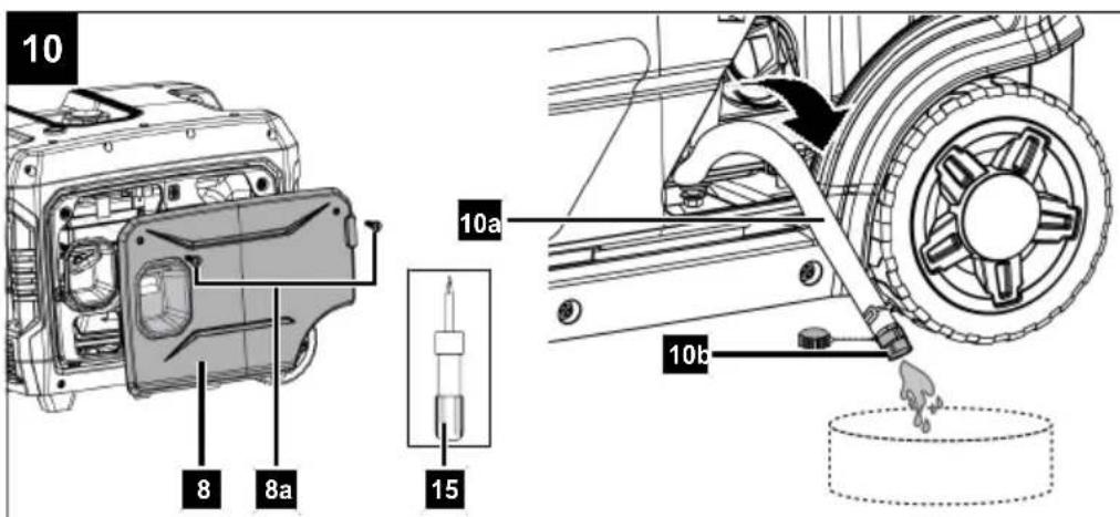
10.2.3 Oil change (Fig. 10)
Change engine oil after 50 hours of operating time.
The engine oil change should be carried out while the engine is at operating temperature.
- Remove the two screws (8a) from the engine cover (8). Use a Phillips screwdriver (15).
- Have a collection bucket to hand.
- Remove the oil drain hose (10a) from its holder to drain the engine oil.
- Open the oil drain plug (10b) and remove the oil dipstick (10).
- Drain the old oil completely.
-
Replace the oil drain plug (10b) and reattach the oil drain hose (10a) to the bracket.
-
Top up with new engine oil as described in 8.2.
- Screw the oil dipstick (10) in again.
- Fit the engine cover (8) using the two screws (8a). Use a Phillips screwdriver (15).
- Dispose of the used oil properly.
10.2.4 Cleaning the air filter (12a) (Fig. 11)
ATTENTION
Risk of damage!
Operating the engine without a filter element or with a damaged filter element can cause engine damage.
- Never run the engine without the air filter element or with a damaged filter element. This would allow dirt into the engine, which would result in severe damage to the engine.
Clean the air filter (12a) every 50 operating hours, replace if necessary.
- Remove the cover (4) by removing the two screws (4a). Use a Phillips screwdriver (15).
- Open the two clamping levers (12b) and remove the air filter cover (12).
- Remove the air filter (12a).
- Do not use harsh cleaners or petrol to clean the filter.
- Clean the elements by knocking them out on a flat surface. If heavily soiled, wash with soapy water, then rinse with clean water and allow to air dry.
- The re-assembly takes place in reverse order.
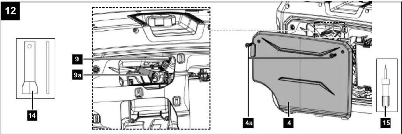
10.2.5 Check spark plug (9) (Fig. 12)
ATTENTION
Only replace the spark plug when the engine is cold!
Check the spark plug for dirt for the first time after 20 operating hours and clean it with a copper wire brush if necessary. Then service the spark plug every 50 operating hours.
- Remove the cover (4) by removing the two screws (4a). Use a Phillips screwdriver (15).
- Pull off the spark plug connector (9a) with a twisting motion.
- Remove the spark plug (9). Use an installation span-ner (14).
- Remove any dirt from the base of the spark plug (9).
- Visually inspect the spark plug (9). Remove any deposits present using a wire brush.
- Check the spark plug gap. Set the electrode gap to 0.6 to 0.7 mm with a feeler gauge.
- The re-assembly takes place in reverse order.
NOTE
A loose spark plug can overheat and cause damage to the engine. Tightening the spark plug too much can damage the thread in the cylinder head.
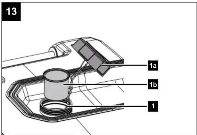
10.2.6 Cleaning the fuel filter insert (1b) (Fig. 13)
Note:
The petrol filter is a fuel filter insert cup, which is located directly under the fuel cap and filters all the fuel that is filled in.
- Screw the tank cover (1a) on. The fuel filler cap (1a) is connected to an anti-loss device in the fuel tank (1) and thus cannot fall off.
- Remove the fuel filter insert (1b). Clean it in a non-flammable solvent or a solvent with a high flash point.
- Reinsert the fuel filter insert (1b).
- Retighten the tank cover (1b).
11 Storage and transport

WARNING
Danger of injury and burning!
The product can start unexpectedly and cause injuries.
- Switch off the motor before carrying out any cleaning or maintenance work.
- Allow the motor to cool down.
- Disconnect the spark plug connector from the spark plug.
- Remove the battery.
• Empty the product completely.
- Clean and check the product for damage.
11.1 Storage

DANGER
Risk of fire and explosion!
Storing the product near potential sources of ignition can result in a fire or an explosion. This can lead to severe burns or death.
- Eliminate possible sources of ignition, such as furnaces, hot water boilers with gas, gas dryers, etc.
ATTENTION
Risk of damage!
If the product is not stored properly, the engine can be damaged.
- Store the product protected against dirt, dust and moisture.
Tool required:
• Phillips screwdriver (15)
- Socket spanner, size 8 mm*
- Fuel extraction pump*
* = may not be included in the scope of delivery!
11.1.1 Preparation for storage (Fig. 5, 12)

WARNING
Do not remove the fuel in enclosed spaces, near fire or when smoking. Petrol fumes can cause explosions and fire.
- Empty the fuel tank using a petrol extraction pump.
- Start the engine and let it run until the remaining fuel is used up.
- Store fuel in tanks specifically designed for this purpose.
- Change the oil at the end of every season.
- Remove the spark plug (9).
- Fill the cylinder with approx. 20 ml of oil from an oil can.
- Pull the pull starter slowly so that the oil protects the inside of the cylinder.
-
Screw the spark plug (9) back in.
-
When the product is taken out of service for an extended period of time, before starting work on or near electrical components, disconnect the battery connection cable (11b) from the engine connection cable (11a). We recommend removing the battery (11) and storing it fully charged in a dry and locked room.
- Store the product in a well-ventilated place or area.
11.1.2 Removing the battery (11) (Fig.)
- Remove the two screws (8a) from the cover (8). Use a Phillips screwdriver (15).
- Remove the battery bracket (11a). Use a 8 mm open-ended spanner.
- Disconnect the battery connection cable (11b) and the engine connection cable (11c).
- Remove the battery (11).
- Place the cover cap on the battery connection cable (11b).
- Fit the battery bracket (11a). Use a 8 mm open-ended spanner.
- Fit the engine cover (8) using the two screws (8a). Use a Phillips screwdriver (15).
Ensure that batteries are secured against unauthorised use (e.g. by children).
Charge the battery during the winter 1-2 times to ensure that the full charging capacity is maintained. Incorrect storage can damage the battery.
11.1.2.1 Charge the battery (12) with the car battery charger (Fig. 5)

DANGER
Danger due to charging the battery incorrectly!
If the charging voltage is too high, there is a risk of the battery exploding.
Always remove the ignition key from the ignition lock when working on the battery.
- The charging current of the battery charger must not exceed 5 A and the charging voltage must not exceed 14.4 V
- Remove the battery (12) as described in section 11.1.2.
- Connect the battery (12) to a suitable car battery charger. Then connect the red cable to the positive terminal (+) and the black cable to the negative terminal (-) of the charging unit.
- Charge the battery (12) for at least 5 hours.
ATTENTION
Danger of short circuit!
- To avoid a short circuit, always disconnect the negative cable (-) from the battery first and reconnect it last.
- When connecting/disconnecting the battery, ensure that the terminals (+/-) do not touch each other and/or the frame.
11.1.3 Drain fuel with a fuel extraction pump (Fig. 6)
In case of storage over a longer period of time, the fuel must be drained.
- Hold a collection bucket under the hose of the fuel extraction pump (not included in the scope of delivery).
- Screw the tank cover (1a) on. The fuel filler cap (1a) is connected to an anti-loss device in the fuel tank (1) and thus cannot fall off.
- Remove the fuel filter insert (1b).
- Push the hose of the fuel extraction pump into the fuel tank (1) and drain out the fuel tank completely using the fuel extraction pump.
- Reinsert the fuel filter insert (1b).
- Retighten the fuel filler cap (1a).
11.2 Transport
- The power generator can be easily and effortlessly moved using the wheels (5). To do this, fold the extendable transport handle (2) upwards and pull the product to the desired storage location.
- The product can be lifted and moved via the handle.
- Secure the product against slipping using a tension strap, for example.
11.2.1 Preparing for transport
- Switch the product off.
- Remove the spark plug connector from the spark plug.
- Drain the motor oil of the warm motor.
- Empty the fuel tank using a petrol extraction pump into an approved container.
12 Repair and ordering spare parts
After repairs or maintenance, make sure that all safety-related parts are installed and are in perfect condition. All parts which may cause injury must be kept where they are inaccessible to children or others.
ATTENTION
According to the German Product Liability Act, no liability is accepted for damage caused by improper repairs or by not using original spare parts.
Such work should be performed by a customer service centre or an authorised specialists. The same applies to accessory parts.
Spare parts and accessories can be obtained from our Service Centre. To do this, scan the QR code on the front page.
Connections and repairs
Connections and repair work on the electrical equipment may only be carried out by electricians.
12.1 Ordering spare parts
Please provide the following information when ordering spare parts:
- Model designation
- Item number
- Type plate data
12.2 Service information
With this product, it is necessary to note that the following parts are subject to natural or usage-related wear, or that the following parts are required as consumables.
Wearing parts*: Spark plug, air filter
* = not included in the scope of delivery!
13 Disposal and recycling
Notes for packaging


The packaging materials are recyclable. Please dispose of packaging in an environmentally friendly manner.
Notes on the disposal of electrical and electronic equipment

Waste electrical and electronic equipment does not belong in household waste, but must be collected and disposed of separately!
- Used batteries that are not installed permanently in the old device must be removed non-destructively before disposal! Their disposal is regulated by the battery act.
- Owners or users of electrical and electronic devices are legally obliged to return them after use.
- The end user is responsible for deleting their personal data from the old device being disposed of!
- The symbol of the crossed-out dustbin means that waste electrical and electronic equipment must not be disposed of with household waste.
- Waste electrical and electronic equipment can be handed in free of charge at the following places:
– Public disposal or collection points (e.g. municipal works yards)
- Points of sale of electrical devices (stationary and online), provided that dealers are obliged to take them back or offer to do so voluntarily.
- Up to three waste electrical devices per type of device, with an edge length of no more than 25 centimetres, can be returned free of charge to the manufacturer without prior purchase of a new device from the manufacturer or taken to another authorised collection point in your vicinity.
- Further supplementary take-back conditions of the manufacturers and distributors can be obtained from the respective customer service.
- If the manufacturer delivers a new electrical appliance to a private household, the manufacturer can arrange for the free collection of the old electrical appliance upon request from the end user. Please contact the manufacturer's customer service for this.
• These statements only apply to devices installed and sold in the countries of the European Union and which are subject to the European Directive 2012/19/EU. In countries outside the European Union, different regulations may apply to the disposal of waste electrical and electronic equipment.
Information on the disposal of used batteries

Used batteries do not belong in household waste, but should be collected and disposed of separately!
- For safe removal of used batteries from the electrical device and for information on their type or chemical system, please refer to the additional information in the operating or assembly instructions.
- Owners or users of batteries are legally obliged to return them after use. The return is limited to household quantities.
- Old batteries may contain pollutants or heavy metals that can harm the environment or human health. Recycling old batteries and using the resources they contain helps to protect these two important issues.
- The plastic and metal parts used can be separated by type and thus recycled.
- The symbol of the crossed-out dustbin means that used batteries must not be disposed of with household waste.
- If the signs Hg, Cd or Pb are also located below the dustbin symbol, this stands for the following:
– Hg: Battery contains more than 0.0005% mercury
– Cd: Battery contains more than 0.002% cadmium
– Pb: Battery contains more than 0.004% lead
- Used batteries can be returned free of charge to the following places:
– Public disposal or collection points (e.g. municipal works yards)
- Battery retail outlets
- Take-back points of the common take-back system for old device batteries
- Take-back point of the manufacturer (if not a member of the common take-back system)
• These statements are only valid for batteries sold in the countries of the European Union and subject to the European Regulation (EU) 2023/1542. Different provisions can apply to the disposal of used batteries in countries outside the European Union.
You can find out how to dispose of the disused device from your local authority or city administration.
Fuels and oils
- Before disposing of the product, the fuel tank and the engine oil tank must be emptied!
- Fuel and engine oil do not belong in household waste or drains, but must be collected or disposed of separately!
- Empty oil and fuel tanks must be disposed of in an environmentally friendly manner.
14 Troubleshooting
The following table shows fault symptoms and describes remedial measures in the event of your product failing to work properly. If you cannot localise and rectify the problem with this, please contact your service workshop.
| Fault Possible cause Remedy | ||
| Engine cannot be started Automatic | tic oil cut-off trips Check oil level, fill with engine oil | |
| Spark plug sooty Clean or replace spark plug | ||
| No fuel Refill fuel / have fuel valve checked | ||
| Product's battery is flat If the product's battery is empty, the engine can only be started using the pull starter. Check the charge level indicator on the battery and charge the battery if necessary. | ||
| Air filter dirty Clean or replace the air filter | ||
| Product has insufficient or no voltage. | Electronics defective Contact the specialist dealer | |
| Overload protection has been triggered | Press the “RESET” button, reduce consumption | |
| Air filter dirty Clean or replace the air filter | ||
15 EU Declaration of Conformity
Translation of the original Declaration of Conformity
Manufacturer:
Scheppach GmbH
Günzburger Straße 69
D-89335 Ichenhausen
We declare under our sole responsibility that the product described here complies with the applicable directives and standards.
Brand: SCHEPPACH
Art. designation: Inverter generator - SG7000i
Art. no. 5906242903
EU directives:
2014/30/EU, 2000/14/EG_2005/88/EG_EU/2024/1208, 2016/1628/EU, 2011/65/EU*,
* The object of the declaration described above fulfils the regulations of the directive 2011/65/EU of the European Parliament and Council from 8th June 2011, on the restriction of the use of certain hazardous substances in electrical and electronic equipment.
Applied standards:
EN ISO 8528-13:2016;
EN-60204-1:2018;
EN 55012:2007+A1;
EN IEC 61000-6-1:2019;
ISO 8528-10:1998;
EN ISO 3744:1995
Conformity assessment procedure:
2000/14/EG\_2005/88/EG\_EU/2024/1208 – Appendix: VI
Guaranteed
sound power level ( L_WA ): 96 dB
Measured
sound power level ( L_WA ): 94.1 dB
Notified body:
TÜV Rheinland LGA Products GmbH, Tillystraße 2, 90431 Nuremberg
Number: 0197
2016/1628/EU
Emission. No: e24*2016/1628*2018/989SRB1/P*0409*00
Documentation authorised representative:
Stefan Hartinger
Günzburger Str. 69
D-89335 Ichenhausen
Division Manager Product Center

Head of Project Management
Sommaire
Günzburger Straße 69
D-89335 Ichenhausen
Remarque :
Günzburger Straße 69
D-89335 Ichenhausen
Division Manager Product Center

Andreas Pecher
Head of Project Management
Indice
Günzburger Straße 69
D-89335 Ichenhausen, Germania
Indicazione:
Günzburger Straße 69
D-89335 Ichenhausen
Division Manager Product Center

Andreas Pecher
Head of Project Management
Inhoudsopgave
Günzburger Straße 69
D-89335 Ichenhausen
Aanwijzing:
9.8 "RESET"-toets (3d) (afb. 9)
230 V-stopcontacten (3i, 3j):
Günzburger Straße 69
D-89335 Ichenhausen
Division Manager Product Center

Andreas Pecher
Head of Project Management
Índice
Günzburger Straße 69
Günzburger Straße 69
D-89335 Ichenhausen
Division Manager Product Center

Andreas Pecher
Head of Project Management
Índice
Günzburger Straße 69
Günzburger Straße 69
D-89335 Ichenhausen
Division Manager Product Center

Andreas Pecher
Head of Project Management
Obsah
Günzburger Straße 69
D-89335 Ichenhausen
Upozornění:
Günzburger Straße 69
D-89335 Ichenhausen
Division Manager Product Center

Andreas Pecher
Head of Project Management
Obsah
Günzburger Straße 69
D-89335 Ichenhausen
Upozornenie:
Günzburger Straße 69
D-89335 Ichenhausen
Division Manager Product Center

Andreas Pecher
Head of Project Management
Tartalomjegyzék
Günzburger Straße 69
D-89335 Ichenhausen
Megjegyzés:
Günzburger Straße 69
D-89335 Ichenhausen
Division Manager Product Center

Andreas Pecher
Head of Project Management
Spis treści
Günzburger Straße 69
D-89335 Ichenhausen
Wskazówka:
Günzburger Straße 69
D-89335 Ichenhausen
Division Manager Product Center

Andreas Pecher
Head of Project Management
Popis sadržaja
1 Uvod.... 175
2 Namjenska uporaba.... 175
3 Opis proizvoda (sl. 1-13).... 175
4 Opseg isporuke (sl. 2).... 176
5 Raspakiravanje 176
6 Tehnički podatci 176
7 Sigurnosne napomene.... 176
8 Prije stavljanja u pogon.... 179
9 Rukovanje 181
10 Čišćenje i održavanje.... 183
11 Skladištenje i transport.... 184
12 Popravak i naručivanje rezervnih dijelova...... 186
13 Zbrinjavanje i recikliranje.... 186
14 Otklanjanje neispravnosti.... 187
15 EU izjava o sukladnosti.... 187
16 Povećani crtež.... 376
Günzburger Straße 69
D-89335 Ichenhausen
Napomena:
Prema važećem njemačkom Zakonu o odgovornosti za proizvode, proizvođač ovog proizvoda ne odgovara za štete koje nastanu na ovom proizvodu ili koje ovaj proizvod uzrokuje u slučaju:
Günzburger Straße 69
D-89335 Ichenhausen
Division Manager Product Center

Andreas Pecher
Head of Project Management
Kazalo
Günzburger Straße 69
D-89335 Ichenhausen
Napotek:
Proizvajalec tega izdelka skladno z veljavnim zakonom o odgovornosti za izdelke ne jamči za poškodbe na tem izdelku ali poškodbe s tem izdelkom, do katerih pride pri:
Günzburger Straße 69
D-89335 Ichenhausen
Division Manager Product Center

Head of Project Management
Sisukord
Günzburger Straße 69
D-89335 Ichenhausen
Juhis:
Günzburger Straße 69
D-89335 Ichenhausen
Division Manager Product Center

Andreas Pecher
Head of Project Management
Turinys
Günzburger Straße 69
D-89335 Ichenhausen
Nuoroda:
Günzburger Straße 69
D-89335 Ichenhausen
2014/30/ES, 2000/14/EB_2005/88/EB_ES/2024/1208, 2016/1628/ES, 2011/65/ES*,
Division Manager Product Center

Andreas Pecher
Head of Project Management
Satura rādītājs
Günzburger Straße 69
Günzburger Straße 69
D-89335 Ichenhausen
Division Manager Product Center

Head of Project Management
Günzburger Straße 69
D-89335 Ichenhausen
Anvisning:
Günzburger Straße 69
Division Manager Product Center

Andreas Pecher
Head of Project Management
Sisällysluettelo
Günzburger Straße 69
D-89335 Ichenhausen
Huomautus:
Günzburger Straße 69
D-89335 Ichenhausen
Division Manager Product Center

Andreas Pecher
Head of Project Management
Indholdsfortegnelse
1 Indledning....274
2 Tilsigtet brug.... 274
3 Produktbeskrivelse (fig. 1-13) 274
4 Leveringsomfang (fig. 2) 275
5 Udpakning.... 275
6 Tekniske data.... 275
7 Sikkerhedsforskrifter 276
8 Før ibrugtagning....278
9 Betjening 280
10 Rengøring og vedligeholdelse.... 281
11 Opbevaring og transport 283
12 Reparation og reservedelsbestilling.... 284
13 Bortskaffelse og genanvendelse.... 285
14 Fejlfinding.... 286
15 EU-overensstemmelseserklæring.... 286
16 Eksplosionstegning 376
Forklaring til symbolerne på produktet
Günzburger Straße 69
D-89335 Ichenhausen, Tyskland
Bemærk:
1 x Inverter-strømgenerator
1 x Brugsanvisning
5 Udpakning

ADVARSEL
Günzburger Straße 69
D-89335 Ichenhausen, Tyskland
Division Manager Product Center

Andreas Pecher
Head of Project Management
Innholdsfortegnelse
Günzburger Straße 69
D-89335 Ichenhausen
Merknad:
Fare for forgiftning!
USB-tilkobling (3m):
11.2.1 Forberedelse for transport
- Slå av produktet.
• Fjern plugghetten fra tennpluggen. - Tapp ut motoroljen fra den varme motoren.
- Tøm drivstofftanken i en godkjent Oppsamlingsbeholder med en drivstoffsugepumpe.
Günzburger Straße 69
D-89335 Ichenhausen
Prosedyrer for samsvarsvurdering:
2000/14/EF\_2005/88/EF\_EU/2024/1208 - Vedlegg: VI
Garantert
lydeffektnivå (LWA): 96 dB
Målt
lydeffektnivå (LWA): 94,1 dB
Oppnevnt instans: TÜV Reihnland
LGA Products GmbH
Tillystraße 2,
90431 Nürnberg
0197
Nummer:
2016/1628/EU
Utslipp. No: e24*2016/1628*2018/989SRB1/P*0409*00
Division Manager Product Center

Andreas Pecher
Head of Project Management
Съдържание
Günzburger Straße 69
D-89335 Ichenhausen, Германия
Указание:
Günzburger Straße 69
D-89335 Ichenhausen
Division Manager Product Center
V. Gordon
Andreas Pecher
Head of Project Management
Günzburger Straße 69
D-89335 Ichenhausen
Υπόδειξη:
Günzburger Straße 69
D-89335 Ichenhausen
EN IEC 61000-6-1:2019,
ISO 8528-10:1998,
EN ISO 3744:1995
Division Manager Product Center

Andreas Pecher
Head of Project Management
Cuprins
Günzburger Straße 69
D-89335 Ichenhausen
Indicatie:
Prize 230 V (3i, 3j):
Günzburger Straße 69
D-89335 Ichenhausen
Division Manager Product Center

Head of Project Management
Sadržaj
1 Uvod.... 349
2 Namenska upotreba.... 349
3 Opis proizvoda (sl. 1-13).... 349
4 Opseg isporuke (sl. 2).... 350
5 Raspakivanje....350
6 Tehnički podaci 350
7 Sigurnosne napomene.... 350
8 Pre puštanja u rad.... 353
9 Rukovanje 355
10 Čišćenje i održavanje.... 357
11 Skladištenje i transport.... 358
12 Popravka i naručivanje rezervnih delova ..... 360
13 Odlaganje na otpad i reciklaža.... 360
14 Pomoć za otklanjanje smetnji.... 361
15 EU izjava o usaglašenosti.... 361
16 Znak eksplozije 376
Günzburger Straße 69
D-89335 Ichenhausen
Napomena:
9.8 Taster "RESET" (3d) (sl. 9)
Ako je aktivirana zaštita od preopterećenja i indikator preopterećenja (3f.2.) zasvetli crveno, taster „RESET“ (3d) može da obnovi izlaznu snagu agregata generatora struje. U tom slučaju nije neophodno da se motor ponovo pokrene.
Ako zaštita od preopterećenja nije okinuta, taster „RESET“ (3d) nema efekta.
- Držite pritisnut taster „RESET“ (3d) 1 sekundu, dok se lampica (crvena) ne ugasi i ne zasvetli indikator rada (3f.3.) zasvetli (zeleno).
9.9 Taster za displej (3f.4.) (Sl. 9)
Günzburger Straße 69
D-89335 Ichenhausen
2000/14/EG\_2005/88/EG\_EU/2024/1208 – Prilog: VI
Garantovani
nivo zvučne snage (LWA):
96 dB
Izmereni
nivo zvučne snage (LWA):
94,1 dB
Imenovano telo:
TÜV Rheinland
LGA Products GmbH
Tillystraße 2,
90431 Nürnberg
0197
Broj:
2016/1628/EU
Emisija. Br: e24*2016/1628*2018/989SRB1/P*0409*00
Lice ovlašćeno za dokumentaciju:
Stefan Hartinger
Günzburger Str. 69
D-89335 Ichenhausen
Division Manager Product Center

Andreas Pecher
Head of Project Management
İçindekiler
Günzburger Straße 69
D-89335 Ichenhausen
İthalatçı:
9.8 "RESET" tuşu (3d) (Res. 9)
Günzburger Straße 69
D-89335 Ichenhausen
Division Manager Product Center

Head of Project Management

Garantie DE
Obvious defects must be reported within 8 days after receipt of the goods, otherwise the purchaser loses all claims due to such defects. We guarantee our machines, if handled correctly, for the duration of the statutory warranty period from handover in such a way that we will replace free of charge any machine part that demonstrably becomes unusable within this period as a result of material or manufacturing defects. For parts that we do not manufacture ourselves, we only provide a warranty to the extent that we are entitled to warranty claims against the upstream suppliers. The purchaser shall bear the costs of fitting the new parts. Claims for conversion and reduction and other claims for damages are excluded.