PBGK 1400 C3 - Petrol tiller PARKSIDE - Free user manual and instructions
Find the device manual for free PBGK 1400 C3 PARKSIDE in PDF.

User questions about PBGK 1400 C3 PARKSIDE
0 question about this device. Answer the ones you know or ask your own.
Ask a new question about this device
Download the instructions for your Petrol tiller in PDF format for free! Find your manual PBGK 1400 C3 - PARKSIDE and take your electronic device back in hand. On this page are published all the documents necessary for the use of your device. PBGK 1400 C3 by PARKSIDE.
USER MANUAL PBGK 1400 C3 PARKSIDE
natural_image
Side view of a small manual tiller with visible blades and wheels (no text or symbols)
text_image
PDF ONLINE www.1idl-service.comPETROL GARDEN TILLER - PBGK 1400 C3 BENZIN-GARTENKULTIVATOR - PBGK 1400 C3 MOTOBINEUSE THERMIQUE - PBGK 1400 C3
GBENICYMT
PETROL GARDEN TILLER
Operating and Safety Instructions
Translation of Original Operating Manual
FR BE CH
MOTOBINEUSE THERMIQUE
Before reading, unfold the page containing the illustrations and familiarise yourself with all functions of the device.
DE AI CH
GB / IE / NI / CY / MT Operating and Safety Instructions Page 01
text_image
Technical diagram showing exploded view of mechanical components with numbered parts labeled 15, 23, and 243
text_image
28 274
text_image
2 10 11 A A 85
text_image
c 23 OHV c6
text_image
C 17 12 3 3 3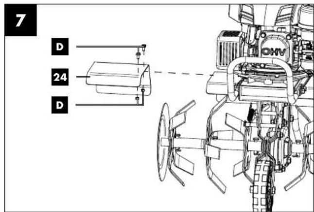
text_image
7 D 24 D OMV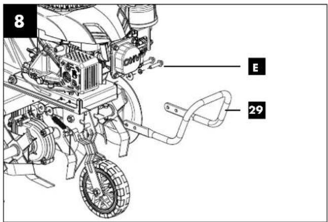
text_image
8 E 29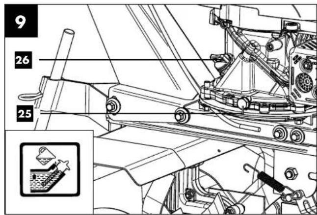
text_image
9 26 25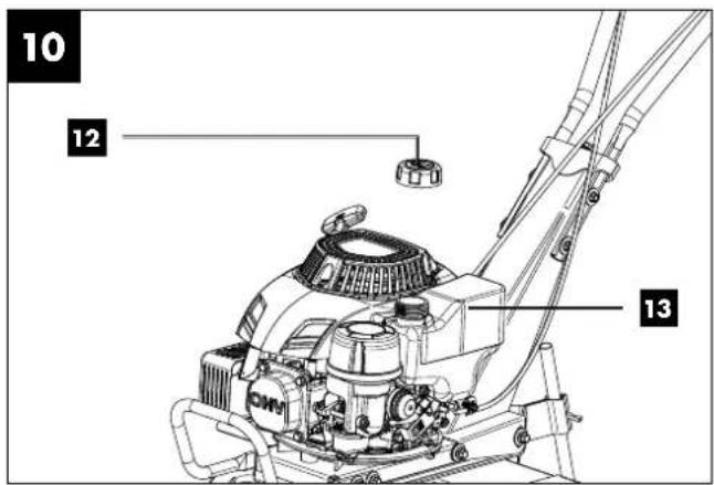
text_image
10 12 13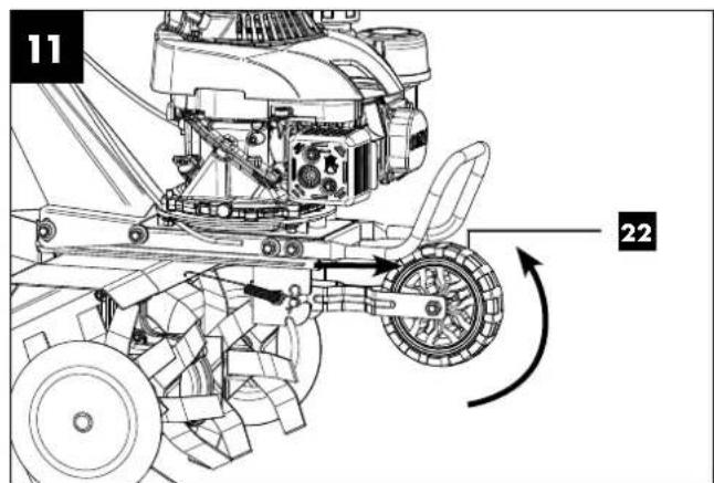
text_image
11 22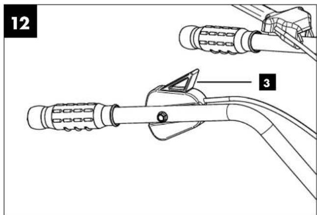
text_image
12 3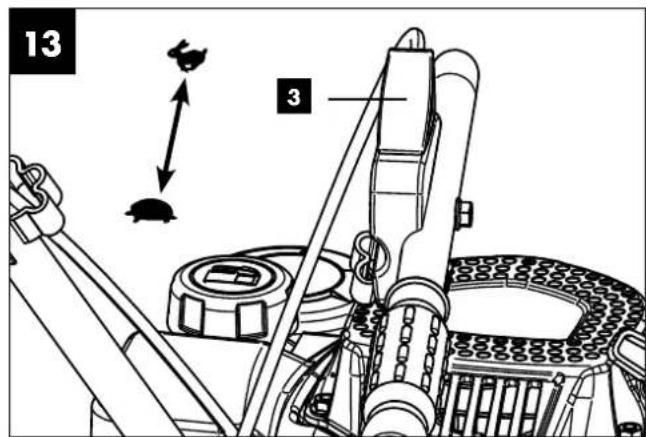
text_image
13 3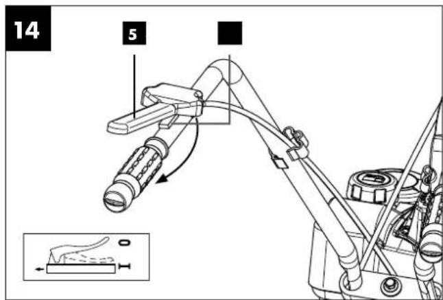
text_image
14 5 0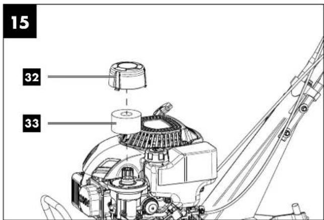
text_image
15 32 33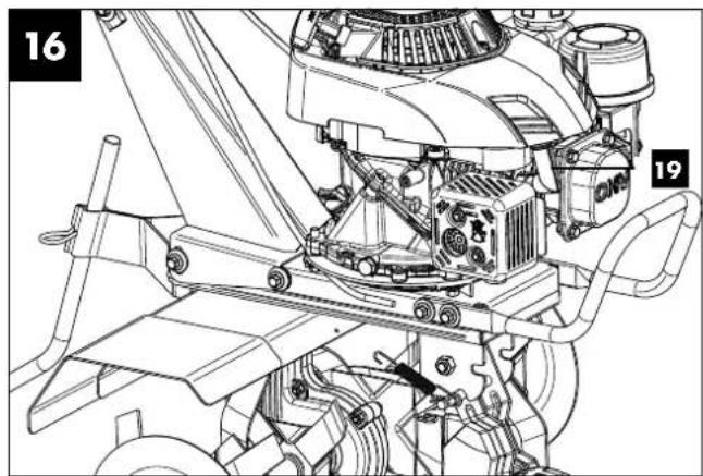
natural_image
Technical line drawing of a mechanical assembly with numbered components (16 and 19), no readable text or symbols present.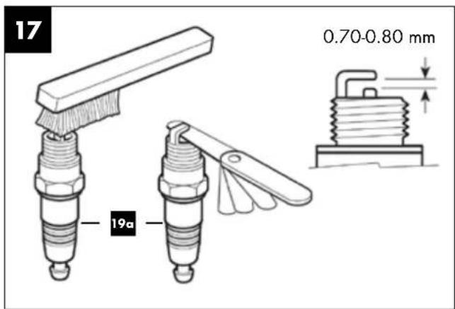
text_image
17 0.70-0.80 mm 19aTable of contents: Page:
- Explanation of the symbols on the device....2
- Introduction......4
- Device description (fig. 1 - 17) ....4
- Scope of delivery (fig. 1 + 2)....4
- Proper use....5
- Safety information....5
- Technical data....7
- Unpacking 8
- Assembly 8
- Before commissioning....9
- Operation....10
- Soil cultivation .... 10
- Transport....11
- Cleaning and maintenance....11
- Storage 13
- Disposal and recycling 13
- Troubleshooting....14
- Warranty certificate....15
- Exploded view....255
- Declaration of conformity....256
1. Explanation of the symbols on the device


Read the operating and safety instructions before start-up and follow them!
Wear eye protection!
Wear hearing protection!
Wear work gloves!
Wear sturdy footwear!
No smoking or naked flames.
Attention! Do not touch moving parts. There is a serious risk of injury!
Observe warnings and safety instructions!
Removing or manipulating the protective or safety devices is prohibited.
Attention: hot surface - risk of burns
Danger due to parts flying off while the engine is running.
The safety distance must be observed.
 | Keep unauthorised persons away from the device. |
 | Guaranteed sound power level in dB |
 | Press the fuel pump primer 3x |
 | Check oil level, fill with engine oil as necessary. |
 | Throttle START (hare) and STOP (tortoise) |
 | Clutch lever: Blade running / STOP (blade at standstill) |
 | Fuel tank |
| DANGER! | Signal word to indicate an imminently hazardous situation which, if not avoided, will result in death or serious injury. |
| WARNING! | Signal word to indicate a potentially hazardous situation which, if not avoided, could result in death or serious injury. |
| CAUTION! | Signal word to indicate a potentially hazardous situation which, if not avoided, could result in minor or moderate injury. |
| NOTE | Signal word to indicate a potentially hazardous situation which, if not avoided, could result in product or property damage. |
2. Introduction
MANUFACTURER:
Scheppach GmbH
Günzburger Straße 69
D-89335 Ichenhausen
DEAR CUSTOMER,
We hope your new tool brings you much enjoyment and success.
NOTE:
In accordance with the applicable product liability laws, the manufacturer of this device assumes no liability for damage to the device or caused by the device arising from:
- Improper handling,
- Failure to comply with the operating instructions.
- Repairs carried out by third parties, unauthorised specialists.
• Installing and replacing non-original spare parts,
• Application other than specified.
Please consider:
Read through the complete text in the operating manual before installing and commissioning the device.
The operating manual is intended to help the user to become familiar with the machine and take advantage of its application possibilities in accordance with the recommendations.
The operating manual includes important instructions for safe, proper and economic operation of the device, for avoiding danger, for minimising repair costs and downtimes, and for increasing the reliability and extending the service life of the device.
In addition to the safety instructions in this operating manual, you must also observe the regulations applicable to the operation of the device in your country.
Keep the operating manual package with the machine at all times and store it in a plastic cover to protect it from dirt and moisture. They must be read and carefully observed by all operating personnel before starting the work.
The device may only be used by personnel who have been trained to use it and who have been instructed with respect to the associated hazards. The required minimum age must be observed.
In addition to the safety instructions in this operating manual and the separate regulations of your country, the generally recognised technical rules relating to the operation of such machines must also be observed.
We accept no liability for accidents or damage that occur due to a failure to observe this manual and the safety instructions.
3. Device description (fig. 1 - 17)
- Pull cable starter
- Right handlebar
- Throttle
- Handle
- Clutch lever
- Clutch lever lock
- Clutch adjusting device
- Left handlebar
- Cable clips
- Handlebar bridge
- Handlebar mount
- Fuel tank cap
- Fuel tank
- Primer
- Left mudguard extension
- Blade
- Left blade extension
- Blade guard
- Spark plug connector
19a. Spark plug
19b. Spark plug wrench - Exhaust pipe
- Wheel locking spring
- Wheel
- Right blade extension
- Right mudguard extension
- Oil drain screw
- Oil filler plug with oil dipstick
- Depth stop split pin
- Depth stop
- Protective safety bar
- Fuel drain plug
- Carburettor
- Air filter cover
- Foam filter
4. Scope of delivery (fig. 1 + 2)
• Petrol garden cultivator (1x)
- Bag with assembly material
- Nut, washer, spring washer, screw (4x) (A)
- Locking pin and washer (1x) (B)
- Split pin and locking pin (2x) (C)
- Nuts and bolts (4x) (D)
- Cable clips (9) (2x)
- Depth stop split pin (27) (1x)
- Handlebar bridge (10)
- Depth stop (28) (1x)
• Left mudguard extension (15) (1x)
• Right mudguard extension (24) (1x)
• Left blade extension (17) (1x)
• Right blade extension (23) (1x)
- Blade guard (18) (2x)
- Protective safety bar (29) with mounting material (E) (4x)
- Spark plug wrench (19b) (1x)
- Operating manual
5. Proper use
The device is designed for chopping and tilling coarse soil and for working in fertiliser, peat and compost in domestic applications.
The machine may only be used in the intended manner. Any use beyond this is improper. The user/operator, not the manufacturer, is responsible for damages or injuries of any type resulting from this.
An element of the intended use is also the observance of the safety instructions, the assembly instructions and the operating information in the operating manual.
Persons who operate and maintain the machine must be familiar with it and must be informed about potential dangers. In addition, the applicable accident prevention regulations must be strictly observed.
Other general occupational health and safety-related rules and regulations must be observed.
The liability of the manufacturer and resulting damages are excluded in the event of modifications of the machine.
Despite use as intended, specific risk factors cannot be entirely eliminated.
Please observe that our equipment was not designed with the intention of use for commercial or industrial purposes. We assume no guarantee if the equipment is used in commercial or industrial applications, or for equivalent work.
6. Safety information
General safety information
⚠ WARNING! Read all instructions, safety instructions, illustrations and specifications provided with this device. Failure to follow all instructions listed below may result in electric shock, fire and/or serious injury.
Save all warnings and instructions for future reference.
General safety regulations
Familiarise yourself with your machine.
The user manual and the markings on the machine must be both read and understood. Learn how and for which purposes the machine is used. Deal with the potential hazards of the machine.
Learn how to control and operate the machine correctly. Learn how to rapidly bring the machine and controls to a stop or shut them down.
All safety instructions and safety notes in the user manual accompanying the machine separately must be read and understood. Do not attempt to operate the machine until you have a thorough understanding of how to operate and maintain the motor and how to avoid accidental injury and/or damage to property.
Safety at the workplace
- Never start or run the motor indoors. The exhaust gases are dangerous and contain carbon monoxide, an odourless and poisonous gas. Only operate this unit in a well-ventilated outdoor area.
- Never operate the machine if there is inadequate visibility or light.
- Never operate the machine on steep inclines.
- Always work in a horizontal line to the ground, never from top to bottom.
Personal safety
- Never operate the machine when under the influence of drugs, alcohol or other medicines which may affect your ability to use the machine properly.
- Wear appropriate clothing. Wear long trousers, boots and gloves. Do not wear loose clothing, shorts or any type of jewellery. Tie long hair up at shoulder length. Always keep hair, clothing and gloves away from moving parts. Loose clothing, jewellery or long hair may become entangled in moving parts.
- Wear protective equipment. Always wear eye protection.
- Protective equipment, such as dust protection masks, safety helmets or hearing protection, which are used in relevant conditions, reduce personal injury.
- Check the machine prior to starting it. Do not remove separating protective devices and keep them in good condition. Ensure that all nuts, bolts, etc. are tight.
- Never operate the machine if it requires repair or if its mechanics are damaged.
- Replace damaged, missing or non-functional parts prior to using the machine. Check leak-tightness. Maintain safe working conditions for the machine.
- Under no circumstances should protective devices be tampered with. Regularly check their functionality.
- The machine must not be used if it cannot be switched on or off using the motor switch. Machines running on fuel that cannot be controlled using the engine switch are hazardous and must be replaced.
- Regularly check that spanners or screw keys have been removed from the machine before starting. Personal injury can result from a spanner or screw key left on a rotating part.
- Keep alert and use common sense when operating the machine.
- Do not bend too far when working. Do not operate the machine barefoot or with sandals or similar light footwear. Wear safety shoes that protect your feet and improve your grip on slippery surfaces.
- Always maintain a firm stance and balance. This allows the machine to be more easily controlled in unexpected situations.
- Avoid unintentional start-up. Ensure that the motor is switched off prior to transporting the machine or carrying out maintenance or servicing work on the unit.
- Transporting the machine or carrying out maintenance or servicing work on the machine while the motor is running can lead to accidents.
Safe handling of operating materials
- Fuel is highly flammable and its vapours can explode if ignited. Take appropriate measures when using fuel so as to reduce the risk of serious personal injury.
- Remain in a clean, well-ventilated outdoor area when filling or draining the tank and use an approved fuel collection container. Smoking prohibited. Avoid ignition sparks, open flames or any other source of ignition in the vicinity of the area when filling fuel or operating the unit. Never fill the tank when inside the building.
- To avoid sparking or arcing, keep earthed conductive objects, such as tools, away from unprotected live electrical parts and connections. They may ignite fumes or vapours.
- Always switch off the motor and allow it to cool down before refilling the tank. Do not remove the cap from the tank or fill up with fuel while the engine is running or warm. Never operate the machine if the fuel system is leaking.
- Slightly open the cap of the tank to release pressure in the tank.
- Do not overfill the tank (to approx. 1.5 cm below the filler neck for space in the event of fuel expanding due to heat generated by the motor).
- Replace the caps of the tank and the container securely and wipe up any spilled fuel. Never operate the unit if the tank cover is not attached.
- Avoid sources of ignition in case of spilled fuel. Do not try to start the motor if fuel has been spilled. Instead, remove the machine from the affected area and avoid sources of ignition until the vapours from the fuel have dissipated.
- Store fuel in specially made containers that have been approved for this purpose.
- Store fuel in a cool, well-ventilated location away from sparks, open flames or other sources of ignition.
- Never store fuel or the machine containing a tank filled with fuel in a building where exhaust fumes could come into contact with ignition sparks, open flames or any other ignition source, such as water heaters, ovens, dryers or similar. Allow the motor to cool down before placing it in a housing.
Notes on use and care of the machine
- Do not lift or carry the machine when the motor is running.
- Do not operate the machine using force.
- Use the right machine for your application. Using the right machine will do the job in a better and safer way.
- Do not change the motor speed regulator settings and do not run the motor at too high a speed. The speed regulator controls the maximum operating speed deemed safe for the motor.
- Do not run the motor fast if the ground is not being worked.
- Only guide the machine at walking pace.
- Take particular care when reversing the machine or pulling it towards you.
-
Do not place your hands or feet near rotating parts.
-
Avoid contact with hot fuel, oil, exhaust fumes and hot surfaces. Do not touch the motor or the silencer. These parts become extremely hot during operation. They also remain hot for a short time after the unit has been switched off. Allow the motor to cool down before carrying out maintenance or adjustment work.
- If the machine starts to make unusual noises or vibrate abnormally, immediately switch off the motor, disconnect the ignition cable and find the cause. Unusual noises or vibrations are generally a warning sign.
- Only use connections and accessories that have been approved by the manufacturer. Failure to comply with this requirement may result in personal injury.
- To prevent an imbalance, worn out or damaged work tools and bolts may only be replaced in sets.
- Service the machine. Check whether any parts in motion are misaligned or blocked. Check parts for breakage or check to see if there is any other condition that might affect the operation of the machine. Have the machine repaired before use if it is damaged. Many accidents occur due to inadequately serviced equipment.
- Clear the motor and silencer of grass, leaves, excessive grease or built-up carbon to reduce the risk of fire.
- Keep cutting tools sharp and clean. Cutting tools with sharp cutting edges that have been properly maintained are less likely to jam and are easier to control.
- Never pour or splash water or any other liquid on the unit. Keep handlebars dry, clean and free of deposits. Clean after each use.
- Adhere to laws and regulations concerning the proper disposal of fuel, oil or the like to protect the environment.
- Keep the machine out of the reach of children when not in use and do not allow persons unfamiliar with the machine or these instructions to operate the machine. The machine is dangerous in the hands of untrained users.
- For safety reasons, the fuel tank and fuel filler cap must be replaced (regularly). To do this, contact a specialist workshop.
- Have damaged exhaust silencers replaced by a specialist workshop.
Corrective maintenance instructions
Switch off the motor prior to cleaning, repairing, inspecting or adjusting the machine and ensure that all parts in motion have been stopped. Disconnect the ignition cable and position the cable away from the spark plug in order to prevent accidental starting.
Have the machine repaired by qualified personnel using only original spare parts.
This ensures that the safety of the machine is maintained.
Special safety regulations for petrol garden cultivators
- Carefully check the soil to be worked and remove debris and hard or sharp objects such as stones, sticks, glass, wire, bones or similar.
-
Do not operate the petrol garden cultivator on soils with large stones or foreign objects that could damage the machine.
-
Do not work over buried electric cables, telephone lines, water and gas pipes, tubes or hoses. If in doubt, contact the utility company or local telephone provider to locate buried service lines.
- Bystanders, children and animals must keep a minimum distance of 23 m. Stop the device immediately if a person approaches.
- Adapt your working method to the local conditions and the device's performance.
- This device is equipped with a clutch. Press the clutch lever and check that it automatically returns to its initial position. If this is not the case, the unit must be re-set by qualified personnel.
- Disengage the clutch before starting the engine.
- Carefully start the engine in accordance with the instructions. Position feet at an appropriate distance from the rotavator cutters.
- The rotavator cutters do not move when the clutch is disengaged. If this is not the case, the unit must be re-set by qualified personnel.
- Always operate the machine from behind. Never walk or stand in front of the machine when the engine is running.
- Always hold the unit with both hands during operation. Hold the handlebars firmly.
- Be aware that the machine may unexpectedly jump up or forward if the rotavator cutters encounter buried obstacles such as large stones, roots or tree stumps.
- If the unit hits a foreign object, stop the engine, disconnect the spark plug, check the machine for any damage and repair the damage before restarting and operating the machine.
- Exercise extreme caution when working backwards or pulling the machine towards you.
- Do not overload the capacity of the machine by working too deep or too fast in one go.
- Never operate the petrol garden cultivator at excessive transport speeds on hard or slippery surfaces.
- Proceed with caution when working on hard ground. The rotavator cutters can get stuck in the ground and propel the petrol garden cultivator forward. If this is the case, release the handlebars and do not hold the machine.
- Exercise caution when working near fences, buildings or buried service lines. The rotating rotavator cutters can cause damage to property or personal injury.
- Exercise extreme caution when working on or over gravel driveways, paths or roads. Watch out for unseen hazards and traffic. Do not carry passengers.
- Never leave the working position when the engine is running.
- Always stop the engine if work is delayed or you are moving from one working location to the next.
- Keep the unit clean of plants and other materials. They can get caught in the rotavator cutters. Stop the engine and disconnect the spark plug before cleaning the rotavator cutters.
Repairs
Only use manufacturer's recommended accessories and replacement parts. If the device should fail despite our quality controls and your maintenance, only allow an authorised specialist workshop to carry out repairs.
Residual risks
Even when the device is being used properly, there will always be certain residual hazards that cannot be completely ruled out. The following potential hazards can arise due to the type and design of the device:
- Ejection of parts of the material being cut
- Damage to hearing if the stipulated hearing protection is not worn
- Inhalation of exhaust gases
⚠ Warning! This product generates an electromagnetic field during operation. This field can impair active or passive medical implants under certain conditions. In order to prevent the risk of serious or deadly injuries, we recommend that persons with medical implants consult with their physician and the manufacturer of the medical implant prior to operating the product.
7. Technical data
| Engine: | 4-stroke, 150 cc |
| Engine output: | 2.7 kW / 3.7 HP |
| Engine working speed: | 3000 min ^-1 |
| Working width: | 360/560 mm |
| Blade ∅: | 260 mm |
| Start system: | Recoil starter system |
| Fuel: | Super E10 petrol |
| Engine oil: | 0.4 l (10W-30 /10W-40) |
| Tank contents: | 0.8 l |
| Weight: | 29.2 kg |
| Spark plug: | LG F6RTC |
| Working depth: | 260 mm |
| Measured sound pressure level L_pA : | 71.23 dB |
| K Measurement uncertainty: | 2 dB |
| Measured sound power level L_wA : | 91 dB |
| K Measurement uncertainty: | 2 dB |
| Guaranteed sound power level L_wA : | 93 dB |
| Vibration value a_hw : | (Left) 11.08 m/s ^2 / (Right) 15.42 m/s ^2 |
| K Measurement uncertainty: | 1.5 m/s ^2 |
Wear hearing protection.
Excessive noise can result in a loss of hearing.
ATTENTION: The vibration value during use may differ from the specified value depending on the circumstances.
The safety measures to protect the operator are based on the estimated exposure under normal operating conditions (taking into account all cycles of use, for example, when the device is switched off, when it is idle or in use).
Keep the noise level and vibration to a minimum!
- Only use devices which are free of defects.
- Maintain and clean the machine at regular intervals.
- Adapt your working methods to the device.
- Do not overload the machine.
- Have the machine checked if necessary.
- Switch the device off if it is not in use.
- Wear gloves.
⚠ Warning!
In case of extended working periods, the operating personnel may suffer circulatory disturbances in their hands (vibration white finger) due to vibrations.
Raynaud's syndrome is a vascular disease that causes the small blood vessels on the fingers and toes to cramp in spasms. The affected areas are no longer supplied with sufficient blood and therefore appear extremely pale. The frequent use of vibrating devices can cause nerve damage in people whose circulation is impaired (e.g. smokers, diabetics) If you notice unusual adverse effects, stop working immediately and seek medical advice.
Observe the following information to reduce hazards:
- Keep your body and especially your hands warm in cold weather.
• Take regular breaks and move your hands to promote circulation. - Ensure as little vibration as possible at the machine via regular maintenance and stable parts on the device.
8. Unpacking
- Open the packaging and carefully remove the device.
- Remove the packaging material, as well as the packaging and transport safety devices (if present).
- Check whether the scope of delivery is complete.
- Check the device and accessory parts for transport damage. In the event of complaints the carrier must be informed immediately. Later claims will not be recognised.
- Familiarise yourself with the product by means of the operating instructions before using for the first time.
- With accessories as well as wearing parts and replacement parts use only original parts. Replacement parts can be obtained from your dealer.
- When ordering please provide our article number as well as type and year of manufacture for your equipment.
DANGER
The device and the packaging are not children's toys! Do not let children play with plastic bags, films or small parts! There is a danger of choking or suffocating!
9. Assembly
⚠ WARNING!
Risk of injury and damage!
The use of incorrect spare parts and accessories can lead to injuries and damage. These could come loose and be flung away. They can also reduce the power of the product.
- Only use original spare parts and accessories from the manufacturer. Original spare parts or accessories can be obtained from your dealer.
- Failure to do so may reduce the power of the product and parts may come loose.
- Failure to observe this will invalidate the manufacturer's warranty.
Note:
Due to the heavy weight of the product, we recommend installation by at least two people.
Some parts of the mower come disassembled. For mounting You need:
- 8 mm open-end spanner (mounting mudguard extension)
- 10 mm open-ended spanner (mounting handlebars, mud-guard extension, protective safety bar)
- 13 mm open-end spanner (mounting handlebars)
• 10 mm socket spanner (mounting handlebars)
The assembly tool is not included in the scope of delivery.
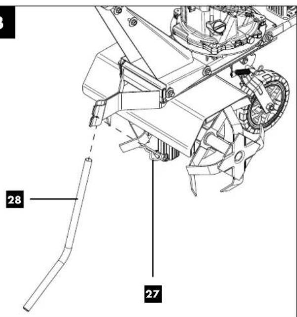
9.1 Fitting the depth stop (Fig. 3)
Fit the depth stop (28) to increase the stability of the machine.
- Insert the depth stop (28) from below into the hole in the frame up to the lower stop.
- Insert the straight end of the split pin (27) into the hole until the split pin (27) engages and cannot be pulled out.
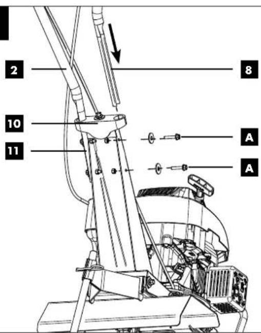
9.2 Installing the handlebars (Fig. 1 + 4)
- Screw the handlebar bridge (10) onto the handlebar mount (11) using a 10 mm socket spanner. Use the M8x35 screw and the washer (B) for this.
- Push the two handlebars (2 and 8) through the handlebar bridge (10). When doing so, make sure that the two cables run crosswise and over the handlebars.
- Hold the two handlebars (2 and 8) against the handlebar mount (11) and insert the screws with two spring washers and the washers (A). Pay attention to the position of the holes. Then secure the connection with one locking nut (A) each.
- Finally, tighten the screws (A) on both sides using two open-ended spanners (10 mm and 13 mm).
- Fit the two cable clips (9) onto the two handlebars (2 and 8) to fasten the cables. And fix the cable clips (9).
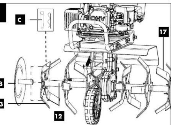
9.3 Fitting the blade guard (18) (Fig. 6)
The blade guard (18) is pre-mounted on the blade extension (17 + 23) when delivered. If you do not use the petrol garden cultivator with the blade extensions (17 + 23) , you must first remove the pre-mounted blade guard (18) from the blade extensions (17 + 23) .
1 To do this, pull the safety cotter pin out of the pin for the blade guard (18) of the blade extension (17 + 23).
2 Now push the blade guard (18) onto the pre-assembled cutter shaft and make sure that the holes match.
3. Insert the safety cotter pin through the holes in the cutter shaft and secure it against slipping out.
4. Repeat the process on the opposite side.
9.4 Fitting the blade extensions (17 + 23) (Fig. 5 - 6)
- Fit the blade extension (17 + 23) into the pre-mounted blade (16) such that the edge of the blade faces the front of the machine.
Note: The blade guard (18) is already pre-mounted when delivered and does not need to be unscrewed from the blade extension (17 + 23).
-
Push both blades into each other. Make sure that the holes match.
-
Insert the safety cotter pin (C) through the holes in the blades and secure it against slipping out.
-
Repeat the process on the opposite side.
⚠ WARNING! When mounting the blades, make sure that they rotate in the correct direction. The blades are not symmetrical and thus cannot be swapped from right to left. The blades must be mounted in the correct direction of rotation.
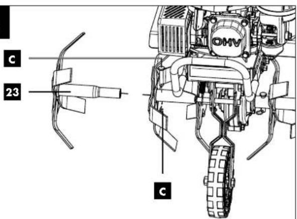
9.5 Fit mudguard extensions (15 and 24) (Fig. 7)
- Fit the mudguard extensions (15 and 24) onto the mudguards already in place from above, as shown in Fig. 7.
- Secure the mudguard extensions (15 and 24) with the screws and nuts (D). Use an 8 mm open-end spanner and a 10 mm open-end spanner for this.
9.6 Fitting the protective safety bar (29) (Fig. 8)
- First unscrew the mounting material (E), i.e. the M8x25 screws, the spring washers and the washers from the motor mount.
- Hold the protective safety bar (29) against the motor mount.
- Fit the M8x25 screws, the spring washers and the washers. Pay attention to the position of the holes.
- Finally, tighten the M8x25 screws on both sides with a 10 mm open-end spanner.
10. Before commissioning
ATTENTION!
Always make sure the device is fully assembled before commissioning!
⚠ WARNING!
Risk to health!
Inhalation of petrol/lubricating oil vapours and exhaust gases can cause serious damage to health, unconsciousness and in extreme cases death.
- Do not breathe petrol/lubricating oil vapours and exhaust gases.
- Only use the product outdoors.
NOTE!
Product damage
Using the product without or with too little engine and gear oil can result in engine damage.
- Fill with petrol and oil before commissioning. The product is supplied without engine and gear oil.
NOTE!
Environmental damage!
Spilled oil can pollute the environment permanently. The liquid is highly toxic and can quickly lead to water pollution.
- Fill/empty oil only on level, paved surfaces.
- Use a filling nozzle or funnel.
- Collect drained oil in a suitable container.
- Immediately wipe up any spilled oil carefully and dispose it according to local regulations.
- Dispose of oil as per local regulations.
NOTE!
Risk of damage!
If incorrectly stored or undrained fuel is used, the carburettor may become clogged or engine operation may be affected.
- Put unused fuel in an airtight vessel and store it in a dark, cool room.
Check before operation
- Check all sides of the engine for oil or fuel leaks.
- Check the engine oil level.
- Check the fuel level -- the tank should be at least half-full.
- Check the air filter condition (see section 14.2).
- Check the condition of the fuel lines.
- Make sure that the spark plug connector (19) is attached to the spark plug (19a).
- Look for signs of damage.
- Check that all protective covers are in place and all screws, nuts and bolts are tightened.
10.1 Filling up with engine oil (Fig. 9)
⚠ Attention!
The petrol garden cultivator is delivered without engine oil. Therefore, ensure that you add oil before starting it up. Use multigrade oil (SAE 10W-30 or 10W-40) for this.
Check the oil level regularly before commissioning. An oil level that is too low can damage the engine.
- Place the petrol garden cultivator on a level, even surface.
- Unscrew the oil filler plug with oil dipstick (26).
- Fill the tank with engine oil using a funnel (not included in scope of delivery). Note the max. filling capacity of 400 ml. Carefully fill the oil up to the lower edge of the filler neck.
- Wipe the oil filler plug and the oil dipstick (26) with a clean, lint-free cloth.
- Reinsert the oil filler plug and oil dipstick (26) and check the oil level without screwing the dipstick tight again.
- The oil level must be within the middle mark on the oil dipstick.
- If the oil level is too low, add the recommended amount of oil (max. 400 ml).
- Then screw the oil filler plug with oil dipstick (26) back in.
10.2 Filling up with petrol (Fig. 10)
⚠️ DANGER!
Risk of fire and explosion!
When filling, fuel may ignite and even explode. This leads to severe burns or death.
- Switch off the engine and let it cool down.
- Keep heat, flames and sparks away.
- Only fill up with fuel outdoors.
- Wear protective gloves.
- Avoid contact with skin and eyes.
- Start the product at a distance of at least 3 m from the fuel filling point.
- Watch out for leaks. If petrol is leaking, do not start the engine.
⚠ Attention!
The petrol garden cultivator is delivered without petrol. It is therefore essential to fill with petrol before commissioning. Use Super E10 petrol for this.
- Clean the area surrounding the filling area. Impurities in the tank lead to operational faults.
- Carefully open the tank filler cap (12) so that any possible overpressure can be relieved.
- Fill the fuel tank (13) with petrol using a funnel (not included in scope of delivery). Note the max. filling capacity of 800 ml. Carefully fill the petrol up to the lower edge of the filler neck.
- Close the tank filler cap (12) again. Ensure that the tank cap is tightly sealed.
- Clean the tank cap and the surroundings.
- Check the tank and fuel lines for leaks.
- Move at least three meters away from the refuelling area before starting the engine.
11. Operation
11.1 Transport wheel (22) (Fig. 11)
The spring locks the wheel holder at different heights and distances from the rotavator cutters.
Fold the transport wheel (22) up when working with the petrol garden cultivator.
Fold the Transport wheel (22) down when transporting the petrol garden cultivator. During transport, tilt the machine backwards so that the rotavator cutters no longer touch the ground. You can pull or push the petrol garden cultivator to the next location.
11.2 Depth stop (28)
⚠ CAUTION! Stop the engine and wait until the blades have come to a complete stop before adjusting the depth stop (28)!
The working depth is set with the depth stop. It supports the operator in regulating the direction and speed of the petrol garden cultivator.
The petrol garden cultivator is slowed down and the working depth increased when the depth setting is lowered. The speed is increased and the working depth reduced when the depth setting is increased. (Fig. 3)
11.3 Setting the working depth (Fig. 3):
- Remove the safety cotter pin (27) from the depth stop (28).
- Move the depth setting to the desired position.
- Secure the depth setting with the safety cotter pin (27).
For heavy soils (depth 100 mm or more), remove the depth stop (28) and let the blades work to a depth of 100 mm by moving them slightly forwards and backwards. Slowly pull the petrol garden cultivator backwards and let the soil slide forward over the blades.
11.4 Starting the engine (Fig. 1, 11, 12, 13, 14)
- Move the transport wheel (22) upwards until the lock engages in the recess provided (Fig. 11).
-
Set the throttle lever (3) to START (hare) (Fig. 13).
-
Press the fuel pump primer (14) (Fig. 1) 3 times.
- Start the engine using the pull starter (1) (Fig. 1). To do this, first pull gently until you feel resistance and then pull with force until you reach the end. Repeat this procedure until the engine starts. If the engine has not started after ten attempts, check the "TROUBLE-SHOOTING" section of this operating manual.
- To operate the blades, pull back the clutch lever lock (6). And then press the clutch lever (5) to activate blade rotation. Keep the clutch lever (5) pressed.
- Release the clutch to stop the blades (Fig. 14).
ATTENTION: Do not tilt the machine excessively! Oil can leak or get into the carburettor, combustion chamber etc. and damage the machine! Exceptions are oil changes or maintenance work! If the machine has to be tilted for maintenance, cleaning or repair work, it must always be tilted so that the spark plug points upwards!
11.5 Switch off (Fig. 13 + 14)
- Release the clutch lever (5) to stop the rotavator cutters.
- Set the throttle lever to STOP (turtle position) to stop the engine.
After the last operation, let the petrol garden cultivator run at idle (hare position) for one to two minutes so that the engine cools down a little.
12. Soil cultivation
⚠ Attention! Only guide the machine at walking pace.
Take particular care when reversing the machine or pulling it towards you.
12.1 Soil tilling
Tilling involves turning over and digging up soil and preparing it for the seedbed.
The optimum working depth is between 100 mm and 150 mm. A petrol garden cultivator also removes unwanted plants from the soil.
The decomposition of these plant components enriches the soil.
Soil that is too dry and decays to dust and thus does not absorb water should not be tilled.
- For this reason, water for a few days before tilling.
Soil that is too wet produces undesirable lumps when tilling.
- For this reason, wait a day or two after heavy rainfall to allow the soil to dry out.
- A properly tilled area that is used immediately after tilling promotes plant growth because moisture is retained in the soil.
-
The actual working depth is determined by the soil type and working conditions. For certain soils, one pass is sufficient to achieve the desired depth. With other soils, the desired depth is only achieved after two or three passes. In this case, the depth setting should be lowered again before each pass. The passes should be carried out alternately lengthwise and widthwise.
-
Do not try to work the soil too deep in the first pass. If the machine jumps or jerks, the unit should be driven over the ground a little faster.
- If the petrol garden cultivator stops and digs in one place, move the handlebar back and forth until the machine moves forward again.
• Excavated stones should be removed.
⚠ WARNING! If you should encounter a foreign object, the machine must be stopped immediately, the spark plug connector removed and the petrol garden cultivator checked for any damage. Do not restart the machine until you are sure that everything is working properly.
12.2 Loosening of soils
CAUTION! If the ground is too hard, it must be broken up before tilling to avoid damaging the blade or other components of the machine.
Tilling involves loosening or digging in areas where plants are growing to remove weeds and loosen the soil. The optimum working depth is less than 50 mm.
13. Transport
⚠ WARNING!
Risk of injury!
Unintended and unexpected start-up of the product may lead to injuries.
- Before loading, switch off the engine and, after the engine has cooled down, remove the spark plug connector from the spark plug.
-
The product can cause severe crushing injuries due to its own weight.
-
Allow the engine to cool down before transporting or loading to avoid burns and to prevent fire hazards.
- When transporting over longer distances, drain the fuel tank completely.
- Hold the petrol garden cultivator by the two handles and tilt it backwards until the machine rests on the transport wheel (22) (see also section 11.1). Pull or push the petrol garden cultivator slowly (walking pace). On smooth and even ground the machine should be pushed, on bumpy ground it is better to pull it.
- Secure the machine on the transport vehicle against rolling, slipping or tipping over.
- Ensure that the machine does not bump into obstacles during transport or that obstacles can fall on the machine. Do not place any objects on the machine or lean anything against the machine.
14. Cleaning and maintenance
⚠ WARNING!
Danger of injury and burning!
The product can start unexpectedly and cause injuries. In addition, temperatures of 80^ C and more can be reached.
- Switch off the motor before carrying out any cleaning or maintenance work.
- Allow the engine to cool down.
- Disconnect the spark plug connector from the spark plug.
⚠ WARNING!
Risk to health!
Inhaling petrol/lubricant vapours may lead to severe health damage, loss of consciousness and, in extreme cases, to death.
- Do not inhale petrol/lubricant vapours.
- Only use the product outdoors.
NOTE!
Risk of damage!
Water entering the housing can cause engine damages. In addition, the jet of a high-pressure cleaner can damage parts of the product.
- Clean the product with a cloth, a hand brush, etc.
- Do not immerse the product in water or any other liquid and do not wash it with a high-pressure cleaner.
| Maintenance plan | |
| Check for maintenance Interval | |
| Loose screws Before commissioning | |
| Check for damage Before commissioning | |
| Check fuel tank for leaks Before commissioning | |
| Clean machine After usage | |
| Clean the spark plug Every 10 operating hours | |
| Clean the air filter Every 10 operating hours | |
| Check the oil level Every 50 operating hours |
NOTE!
Environmental damage!
Spilled oil can pollute the environment permanently. The liquid is highly toxic and can quickly lead to water pollution.
- Fill/empty oil only on level, paved surfaces.
- Use a filling nozzle or funnel.
- Collect drained oil in a suitable container.
- Immediately wipe up any spilled oil carefully and dispose it according to local regulations.
- Dispose of oil as per local regulations.
14.1 Oil change (Fig. 9)
The engine oil change should be carried out while the motor is at operating temperature and switched off.
Use only engine oil (SAE 10W-30 or SAE 10W-40).
- Place the petrol garden cultivator on a level, even surface.
- Place a suitable collection container under the oil drain screw (25).
- Use an open-end spanner size 10 mm (not included in the scope of delivery) to open the oil drain screw (25) and drain the engine oil.
- After you have drained the engine oil completely, tighten the oil drain screw (25) again.
- Now unscrew the oil filler plug with oil dipstick (26) anticlockwise.
- Fill up with fresh engine oil and check the oil level (see 10.1).
- Then screw the oil filler plug with oil dipstick (26) back in clockwise.
14.2 Air filter maintenance (Fig. 15)
⚠️ DANGER!
Risk of fire and explosion!
If not cleaned correctly, fuel may ignite and even explode. This leads to severe burns or death.
- Clean the air filter only by knocking out or blowing out with compressed air.
- Never use petrol or flammable solvents to clean the air filter.
NOTE!
Risk of damage!
Operating the engine without the filter element in place can cause engine damage.
- Never run the engine without the air filter element in place.
A fouled air filter insert diminishes the engine output due to reduced air supply to the carburettor. Regular inspection is therefore essential.
The air filter should be checked every 10 operating hours and cleaned as required.
- Turn and pull the bayonet catch of the air filter cover (32) to open it.
- Check the air filter cover (32) for holes or cracks. Replace any damaged insert.
- Wipe off dirt on the inside of the filter housing with a clean moist cloth. Make sure that no direct enters the opening.
- Remove the foam filter (33). Check it for damage and replace it if necessary.
- Blow out the foam filter (33) thoroughly with compressed air.
- Replace the clean foam filter (33) and screw the air filter cover (32) tight. To do this, press and turn the bayonet catch of the air filter cover (32) to close it.
14.3 Cleaning / replacing the spark plug (Fig. 16, 17)
⚠️ ATTENTION: Only replace the spark plug when the engine is cold!
Check the spark plug for dirt and grime after 10 operating hours and if necessary, clean it with a copper wire brush.
Thereafter, replace the spark plug every 50 operating hours or if necessary.
- Disconnect the spark plug connector (19) and remove any dirt in the spark plug area.
- Unscrew the spark plug (19a) with the supplied spark plug wrench and check this.
-
Check the insulation. Replace the spark plug (19a) if it is damaged, e.g. cracked or fragmented.
-
Clean the spark plug electrodes with a wire brush.
-
Check the electrode gap and adjust it using a feeler gauge. To make sure that the engine remains efficient, the spark plug (19a) must have the right electrode gap (0.7 - 0.8 mm).
-
Screw the spark plug (19a) back in by hand and tighten it about 1/4 turn with the spark plug wrench.
-
Place the spark plug connector (19) on the spark plug (19a).
ATTENTION!
A loose spark plug can overheat and cause damage to the engine. If you tighten the spark plug too much, the thread in the cylinder head may be damaged.
14.4 Pump out petrol with a petrol extraction pump
The petrol must be drained in the event of storage over a longer period of time or for transport.
⚠ WARNING!
Risk to health!
Inhalation of petrol/lubricating oil vapours and exhaust gases can cause serious damage to health, unconsciousness and in extreme cases death.
- Do not breathe petrol/lubricating oil vapours and exhaust gases.
-
Empty out fuel only outdoors.
-
Hold a collection container under the hose of the petrol extraction pump (not included in the scope of delivery).
- Unscrew and remove the fuel tank filler cap (12).
- Push the hose of the petrol suction pump into the fuel tank and pump out the petrol completely using the petrol suction pump.
- Retighten the fuel tank filler cap (12).
14.5 Adjusting the clutch
The clutch play changes with the wear of the clutch. To enable proper operation, the clutch cable must be adjusted.
- Set the clutch lever (5) to the original position using the adjuster (7).
- To do this, tighten the counternut with a 12 mm spanner (not included in the scope of delivery) until the clutch engages properly again.
Please provide the following information in the event of any enquiries:
• Data of machine type plate
• Data of motor type plate
Important note in the case of repairs:
When returning the device for repair, please ensure for safety reasons that it is free of oil and fuel when it is sent to the service centre.
14.6 Ordering spare parts
Please provide the following information when ordering replacement parts:
- Device type
• Device article number
Spare parts / accessories
Fuel suction pump - Article no.: 7907600001
Fuel tank - Article no.: 5911249037
Fuel tank cap - Article no.: 5911240 031
14.7 Service information
With this product, it is necessary to note that the following parts are subject to natural or usage-related wear, or that the following parts are required as consumables.
Wearing parts*: Spark plugs, blades, air filter, all operating materials
* may not be included in the scope of supply!
15. Storage
⚠️ DANGER
Risk of fire and explosion!
Storing the product near potential sources of ignition can result in a fire or an explosion. This leads to severe burns or death.
- Eliminate possible sources of ignition, such as furnaces, hot water boilers with gas, gas dryers, etc.
NOTE!
Risk of damage!
If the product is not stored properly, the engine can be damaged.
- Store the product protected against dirt, dust and moisture.
15.1 Storage during extended breaks in operation:
If the petrol garden cultivator will not be used for a period of more than 30 days, the following measures must be taken to prepare your petrol garden cultivator for storage.
- Empty the fuel tank completely (see section 14.4). Stored petrol containing ethanol or MTBE becomes stale within 30 days. Stale petrol has a high rubber content and can thus clog the carburettor and restrict the petrol supply.
- Start the engine and let it run until it stops. This ensures that no petrol remains in the carburettor. This prevents deposits from forming in the carburettor and potentially damaging the engine.
- Drain the engine oil from the engine while it is still warm. Fill with new oil (see section 14.1.).
- Allow the engine to cool down. Remove the spark plug (19a) and fill 30 ml of good quality engine oil into the cylinder. Pull the starter rope slowly to distribute the oil. Replace the spark plug (19a).
⚠️ ATTENTION! Remove the spark plug and drain all the oil from the cylinder before restarting the machine after storage.
- Use a clean cloth to clean the outside of the petrol garden cultivator and remove any dirt from the ventilation slots.
ATTENTION! Do not use aggressive detergents or mineral oil-based cleaning agents to clean plastic parts. Chemicals can damage plastics.
- Check for loosened or damaged parts. Repair or replace damaged parts and tighten loosened screws and nuts.
-
Remove the blades. Clean the blades and grease them to prevent rusting. Refit the blades.
-
Lightly grease the wheel axles. Grease the throttle cable and all visible moving parts. Do not dismantle the engine cover.
- Store the petrol garden cultivator in an upright position in a clean, dry building with good ventilation.
⚠️ ATTENTION! Do not store the petrol garden cultivator whilst still filled with fuel in an unventilated place where fuel vapours may come into contact with sparks, signal lamps or other sources of ignition. Use only approved fuel tanks.
Store the device and its accessories in a dark, dry and frost-free place that is inaccessible to children. The optimum storage temperature lies between 5 and 30 °C.
Store the device in its original packaging.
Cover the device to protect it from dust or moisture.
Store the operating manual with the device.
16. Disposal and recycling
Information on packaging


The packaging materials are recyclable. Please dispose of packaging in an environmentally friendly manner.
Contact your local refuse disposal authority for more details of how to dispose of your worn-out electrical devices.
Fuels and oils
- Before disposing of the unit, the fuel tank and the engine oil tank must be emptied!
- Fuel and engine oil do not belong in household waste or drains, but must be collected or disposed of separately!
- Empty oil and fuel tanks must be disposed of in an environmentally friendly manner.
17. Troubleshooting
| Problem Cause Solution | ||
| The engine does not start. | 1. The clutch lever is not in the correct position.2. The tank is empty.3. The air filter components are contaminated.4. The spark plug is loose.5. Spark plug cable not properly secured.6. Wrong spark plug electrode gap.7. Spark plug defective.8. Too much fuel in the carburettor. | 1. Set the clutch lever to the correct position.2. Fill the tank.3. Clean the air filter components.4. Tighten the spark plug to 25-30 Nm.5. Attach the cable to the spark plug.6. Set the distance between the electrodes to 0.7 to 0.8 mm.7. Insert a new spark plug in the correct position.8. Remove the air filter and pull the starter cord repeatedly until the carburettor is clean. Reinsert the air filter. |
| Engine is difficult to start or loses power | 1. Ignition module defective.2. Dirt, water or mould in the fuel tank.3. The air filter components are contaminated. | 1. Contact the customer service department.2. Empty the tank, clean it and fill it with fresh fuel.3. Clean the air filter components. |
| The engine runs unevenly | 1. The air filter components are contaminated.2. The clutch lever is blocked by foreign objects.3. The cooling fins and air intakes under the engine are blocked | 1. Clean the air filter components.2. Remove foreign bodies.3. Remove foreign bodies from the cooling fins and air inlets |
| Engine stalls at high speeds | 1. The electrode gap at the spark plug is too small. | 1. Adjust the electrode gap to 0.7 to 0.8 mm. |
| Motor is overheated | 1. The cooling air flow is obstructed.2. Spark plug defective. | 1. Remove all foreign objects from the frame, fan, air inlets and cooling fins2. Fit an LG F6TC spark plug |
| Engine vibrates abnormally | 1. The blades have not been assembled correctly. The blades are not balanced. | 1. Check that all parts of the machine are correctly assembled. |
18. Warranty certificate
Dear Customer,
All of our products undergo strict quality checks to ensure that they reach you in perfect condition. In the unlikely event that your device develops a fault, please contact our service department at the address shown on this guarantee card. Of course, if you would prefer to call us then we are also happy to offer our assistance under the service number printed below. Please note the following terms under which guarantee claims can be made:
- These guarantee terms cover additional guarantee rights and do not affect your statutory warranty rights. We do not charge you for this guarantee.
- Our guarantee only covers problems caused by material or manufacturing defects, and it is restricted to the rectification of these defects or replacement of the device. Please note that our devices have not been designed for use in commercial, trade or industrial applications. Consequently, the guarantee is invalidated if the equipment is used in commercial, trade or industrial applications or for other equivalent activities. The following are also excluded from our guarantee: compensation for transport damage, damage caused by failure to comply with the installation/assembly instructions or damage caused by unprofessional installation, failure to comply with the operating instructions (e.g. connection to the wrong mains voltage or current type), misuse or inappropriate use (such as overloading of the device or use of non-approved tools or accessories), failure to comply with the maintenance and safety regulations, ingress of foreign bodies into the device (e.g. sand, stones or dust), effects of force or external influences (e.g. damage caused by the device being dropped) and normal wear resulting from proper operation of the device.
The guarantee is rendered null and void if any attempt is made to tamper with the device.
- The guarantee is valid for a period of 3 years starting from the purchase date of the device. Guarantee claims should be submitted before the end of the guarantee period within two weeks of the defect being noticed. No guarantee claims will be accepted after the end of the guarantee period. The original guarantee period remains applicable to the device even if repairs are carried out or parts are replaced. In such cases, the work performed or parts fitted will not result in an extension of the guarantee period, and no new guarantee will become active for the work performed or parts fitted. This also applies when an on-site service is used.
- In order to assert your guarantee claim, please contact the service partner shown below. If the complaint is within the guarantee period, we will provide you with a return slip, with which you can return your defective device free of charge to us. It would help us if you could describe the nature of the problem in as much detail as possible. If the defect is covered by our guarantee then your device will either be repaired immediately and returned to you, or we will send you a new device.
Of course, we are also happy offer a chargeable repair service for any defects which are not covered by the scope of this guarantee or for units which are no longer covered. To take advantage of this service, please send the device to our service address.
Service-Hotline (GB): Service-Hotline (IE): Service-Hotline (NI)
00800 4003 4003 00800 4003 4003 00800 4003 4003
(0,00 EUR/Min.) (0,00 EUR/Min.) (0,00 EUR/Min.)
Service-Email (GB): Service-Email (IE): Service-Email (NI):
service.GB@scheppach.com
service.IE@scheppach.com
service.NI@scheppach.com
Service Address (GB): Service Address (IE): Service Address (NI):
Forest Park & Garden
LetMeRepair
Forest Park & Garden
Coed Court, Taffsmead Road
1 Langlands Court / Kelvin South Business Park
Coed Court, Taffsmead Road
Treforest, Ind. Estate, Pontypridd CF375SW CF375SW
East Kilbride G75 0YB
Treforest, Ind. Estate, Pontypridd
Service-Hotline (CY):
00800 4003 4003
(0,00 EUR/Min.) (0,00 EUR/Min.)
service.IT@scheppach.com
Service Address (CY):
GEORGE C SOLOMONIDES & SON LTD
PO.BOX 56236 / 169, LEONTIOS A'
GR - 3305 LIMASSOL/CYPRUS
At www.lidl-service.com you can download this and many more manuals, product videos plus installation software.
The QR code takes you directly to the Lidl service page (www.lidl-service.com) and you can open your operating manual by entering the article number (IAN) 415639_2204.
Inhalt:
Seite:
Günzburger Straße 69
D-89335 Ichenhausen
VEREHRTER KUNDE,
service.AT@scheppach.com
service.CH@scheppach.com
Service Adresse (DE): Service Adresse (AT): Service Adresse (CH):
Scheppach GmbH Gausch Hubert
Klaus-Häberling AG
Günzburger Str. 69
Günzburger Straße 69
D-89335 Ichenhausen
CHER CLIENT,
Service-hotline (BE):
00800 4003 4003
(0,00 €/Min.)
Service-Hotline (CH):
00800 4003 4003
(0,00 €/Min.)
Email du service (FR):
service.FR@scheppach.com
E-mailadres (BE):
service.BE@scheppach.com
Service-Email (CH):
service.CH@scheppach.com
Scheppach France Strassburg
2, Impasse Jean Millot
FR - 6700 Strasbourg
Serviceadres (BE):
Service Center Bruyninckx
Guldendelle 30
BE - 1930 Zventem (Nossegem)
Günzburger Straße 69
D-89335 Ichenhausen
GEACHTE KLANT,
11.4 Motor starten (afb. 1, 11, 12, 13, 14)
Service-hotline (BE):
00800 4003 4003
(0,00 €/Min.)
E-mailadres / Email du service (NL):
service.NL@scheppach.com
E-mailadres (BE):
service.BE@scheppach.com
Serviceadres / Adresse du service (NL):
Günzburger Straße 69
D-89335 Ichenhausen
VÁŽENÝ ZÁKAZNÍKU,
Günzburger Straße 69
D-89335 Ichenhausen
SZANOWNY KLIENCIE,
Günzburger Straße 69
D-89335 Ichenhausen
VÁŽENÝ ZÁKAZNÍK,
Günzburger Straße 69
Günzburger Straße 69
D-89335 Ichenhausen
KÆRE KUNDE
Günzburger Straße 69
89335 Ichenhausen, Germania
GENTILE CLIENTE,
service.IT@scheppach.com
Service-Email (CH):
service.CH@scheppach.com
Günzburger Straße 69
D-89335 Ichenhausen
KEDVES ÜGYFELÜNK!
Günzburger Straße 69
D-89335 Ichenhausen
SPOŠTOVANI KUPEC,
želimo vam veliko veselja in uspeha pri delu z vašo novo napravo.
NAPOTEK:
Günzburger Straße 69
Günzburger Straße 69
D-89335 Ichenhausen
CIJENJENI KUPČE,
service.HR@scheppach.com
Usluga-Adresa (HR):
Microtec sistemi d.o.o
Ilirska 33
HR - 10000 Zagreb / Croatia

text_image
PDF ONLINE www.idi-service.comNa stranici www.lidl-service.com možete preuzeti ovaj i mnogo drugih priručnika, filmova o proizvodima i instalacijski softver.
S pomoću QR koda izravno prelazite na stranicu Lidl Service (www.lidl-service.com) i unošenjem broja artikla (IAN) 415639_2204 možete otvoriti svoj priručnik za uporabu.
Cuprins: Pagină:
Günzburger Straße 69
D-89335 Ichenhausen
STIMATE CLIENT,
Hotline serviciu (RO):
00800 4003 4003
(0,00 EUR/Min.)
Serviciu de e-mail (RO):
service.RO@scheppach.com
Adresa serviciu (RO):
Machine House S.R.L.
Günzburger Straße 69
D-89335 Ichenhausen, Германия
УВАЖАЕМИ КЛИЕНТИ,
Günzburger Straße 69
D-89335 Ichenhausen
ΑΞΙΟΤΙΜΕ ΠΕΛΑΤΗ,
service.GR@scheppach.com
text_image
Exploded view diagram of a mechanical assembly with numbered parts and Chinese labelsEC Declaration of Conformity
Translation of the original EC declaration of conformity
Standard references:
EN 709:1997+A4:2009; EN 709:1997+A4/AC; EN ISO 14982:2009; EN ISO 3744:1995; ISO 11094:1991
This declaration of conformity is issued under the sole responsibility of the manufacturer.
Subject to change without notice
Documents registrar: Tobias Ihle
Günzburger Str. 69, D-89335 Ichenhausen


CE
SCHEPPACH GMBH
Günzburger Str. 69
D-89335 Ichenhausen

FSC
www.fsc.org
MIX
Paper from responsible sources
C135543

FSC
www.fsc.org
MIXTE