
MB 40 - Pillar drill FESTOOL - Free user manual and instructions
Find the device manual for free MB 40 FESTOOL in PDF.

| Product type | Drill press (mobile drilling accessory) |
| Brand | Festool |
| Model | MB 40 |
| Compatibility | Festool cordless drill drivers TDC 18/4, C 18, T 18+3 (FastFix!), CXS 18, CXS 12, TXS 18, TXS 12, TPC 18/4 |
| Max. drilling diameter (Forstner bits, softwood) | 40 mm |
| Max. drilling diameter (twist drills, softwood) | 16 mm |
| Stroke with depth stop and spring | 187 mm |
| Stroke without depth stop and without spring | 203 mm |
| Depth stop adjustment range | 0 - 50 mm |
| Base plate dimensions | 110 x 114 mm |
| Total height | 312 mm |
| Weight (without accessories) | 1.4 kg |
| Dust extraction connection | ∅ 27 mm |
| Series drilling system | 32 mm grid |
| Removable spring | Yes |
| Power supply | Via the power tool (battery) |
| Machinable materials | Metal, wood, plastics and similar materials |
| Intended use | Precise drilling in metal, wood, plastics |
| Safety | Detailed safety instructions in the manual: wear PPE, do not use in rain, etc. |
| Maintenance | Regular cleaning, lubrication with Festool LFC 9022/50 oil |
| Spare parts and repairability | Genuine Festool parts, repairs by authorized workshops |
Frequently Asked Questions - MB 40 FESTOOL
User questions about MB 40 FESTOOL
0 question about this device. Answer the ones you know or ask your own.
Ask a new question about this device
Download the instructions for your Pillar drill in PDF format for free! Find your manual MB 40 - FESTOOL and take your electronic device back in hand. On this page are published all the documents necessary for the use of your device. MB 40 by FESTOOL.
USER MANUAL MB 40 FESTOOL
natural_image
Mechanical device with spring and base mount, no visible text or symbols1

2
7
natural_image
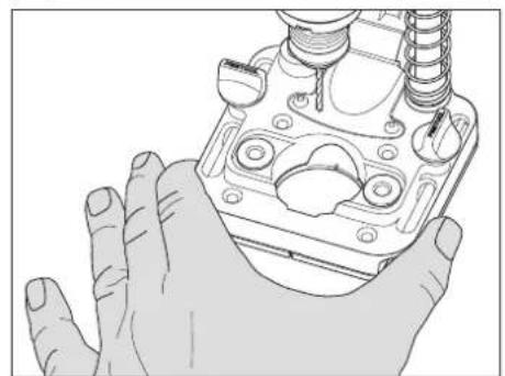
Illustration of a hand holding a mechanical component with threaded ports and housing (no text or symbols)
natural_image
Hand holding a mechanical clamp or tool with a dial indicator (no text or symbols visible)
natural_image
Illustration of a hand holding a mechanical component with no visible text or symbols
natural_image
Line drawing of a hand using a tool to adjust or install a mechanical component (no text or symbols visible)

1 Symbole

Warning of general danger

Warning - risk of burns

Read the operating manual and safety warnings.

Wear protective gloves when changing tools.

Wear protective goggles.

Remove the battery pack.

Only fit by hand.

Screw drive used.

Risk of crushing fingers and hands.

Tip or advice
2 Safety warnings

WARNING! Read all safety warnings, instructions, illustrations and specifications provided with this power tool. Failure to follow all instructions listed below may result in electric shock, fire and/or serious injury.
Save all warnings and instructions for future reference.
Observe the operating manual of the power tool.
- Do not manipulate or block controls, e.g. the on/off switch.
- Wear suitable personal protective equipment: Ear protection, safety goggles, a dust mask for work that generates dust.
- Do not wear loose-fitting clothing or jewellery. If you have long hair, wear a hairnet or tie your hair up. Keep hair and clothing away from moving parts.
Loose-fitting clothing, jewellery or long hair can be caught by moving parts. - Do not use any insertion tools or accessories that the manufacturer has not specially designed or recommended for
the mobile hole drilling attachment. Just because you can attach accessories or insertion tools to your mobile hole drilling attachment does not guarantee that they can be used safely. This may increase the risk of injury, accelerate the wear on the mobile hole drilling attachment and decrease the quality of the working results.
- Depending on the type and use of the accessory, particles, the insertion tool or parts of the insertion tool could come loose. This can lead to increased exposure to dust and to unexpected movements. Wear suitable personal protective equipment. Be prepared for a high reaction torque, which may cause the power tool to turn and lead to injury.
- Do not use or store the mobile hole drilling attachment in the rain or in damp surroundings.
- Place the mobile hole drilling attachment on a solid and even surface. If the mobile hole drilling attachment slides or tilts, it may not be possible to control the power tool safely and reliably.
- This device must not be used by persons (including children) with reduced physical, sensory or mental capabilities or lack of experience and knowledge. Children must be supervised to ensure that they do not play with the device.
2.1 Safety instructions when using long drill bits
- Never operate at higher speed than the maximum speed rating of the drill bit. At higher speeds, the bit is likely to bend if allowed to rotate freely without contacting the workpiece, resulting in personal injury.
- Always start drilling at low speed and with the bit tip in contact with the workpiece. At higher speeds, the bit is likely to bend if allowed to rotate freely without contacting the workpiece, resulting in personal injury.
- Apply pressure only in direct line with the bit and do not apply excessive pressure.
Bits can bend causing breakage or loss of control, resulting in personal injury.
3 Intended use
The MB 40 mobile hole drilling attachment is specifically intended for the precise drilling of holes in metal, wood, plastics and similar materials.
The MB 40 mobile hole drilling attachment is specifically intended for use with Festool cordless drills TDC 18/4, C 18, T 18+3 (FastFix!), CXS 18, CXS 12, TXS 18, TXS 12 and the cordless percussion drill TPC 18/4.

The user is liable for improper or non-intended use.
4 Technical data
| Mobile hole drilling attachment MB 40 | |
| Mount FastFix | |
| Machine compatibility TDC 18/4, TPC 18/4, C 18, T 18+3 (FastFix!), CXS 18, CXS 12, TXS 18, TXS 12 | |
| Suitable attachments WH-CE CENTROTEC, BF-FX 10, KC 13-1/2-K-FFP, KC 13-1/2-MMFP | |
| Suitable fences and adapters Guide rail adapter FSA-MB 40, parallel side fence incl. fence for end face holes PA-MB 40 | |
| Max. drilling diameter with Forstner drill bits in softwood | 40 mm (1-9/16") |
| Max. drilling diameter with auger bits in softwood 16 mm (5/8") | |
| Dust extraction connection Dia. 27 mm (dia. 1-1/16") | |
| Dimensions of base plate 110 mm x 114 mm (4-11/32" x 4-1/2") | |
| Height of MB 40 312 mm (12-9/32") | |
| Setting range of depth stop 0 mm-50 mm (0"-2") | |
| Hole series system Contact spacing: 32 mm (1-1/4") for 3 mm (1/8") and 5 mm (3/16") holes | |
| Removable spring Yes | |
| Max. screw diameter for mounting the MB 40 on templates and fixtures | 4 mm (5/32") |
| Weight (without hole series pins, without tool chuck or keyless chuck, without fences or adapters, incl. spring) | 1.4 kg (3.09 lbs) |
| Stroke with depth stop, incl. spring 187 mm (7-3/8") | |
| Stroke without depth stop, without spring 203 mm (8") | |
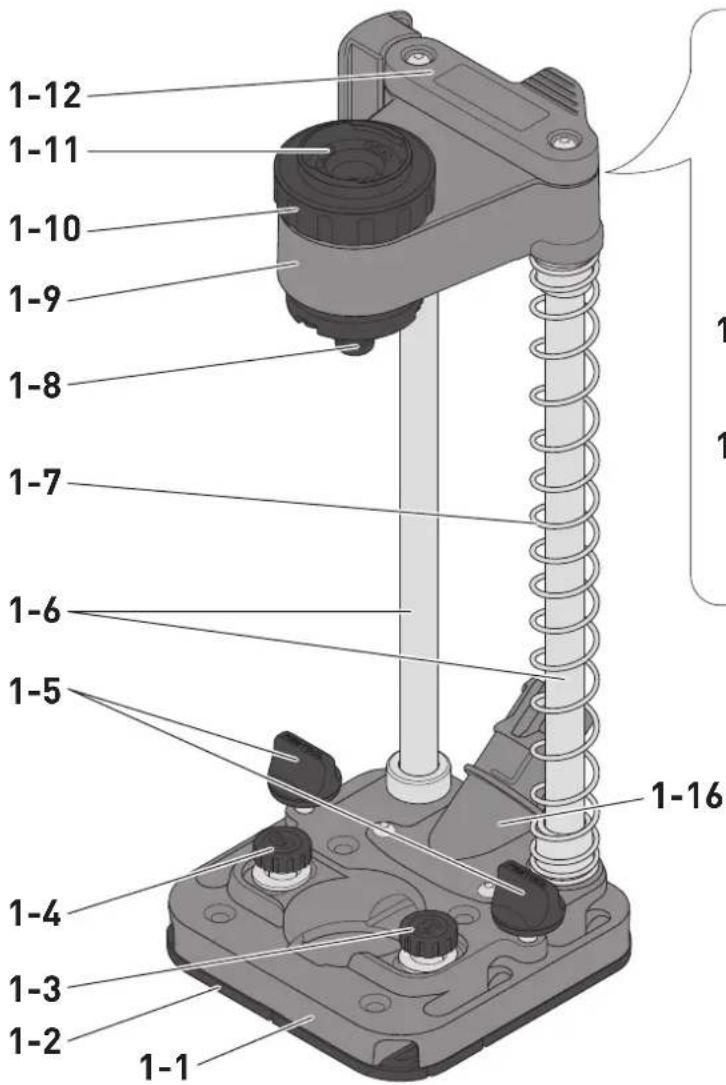
5 Parts of the device / Functional description
| [1-1] | Base plate |
| [1-2] | Lining |
| [1-3] | Hole series pin dia. 3 mm (1/8") |
| [1-4] | Hole series pin dia. 5 mm (3/16") |
| [1-5] | Rotary knob (clamping of fences) |
| [1-6] | Support |
[1-7] Pressure spring
[1-8] Drill spindle
[1-9] Carriage
[1-10] Lock nut
[1-11] FastFix fixture
[1-12] Fence
[1-13] Rotary knob (clamping of depth stop)
[1-14] Rotary knob (clamping of carriage)
[1-15] Depth stop with scale
[1-16] Extractor connector
The specified illustrations appear at the beginning of the Operating Instructions.
6 Assembly

WARNING
Risk of injury
- Remove the power tool from the mobile hole drilling attachment or remove the battery pack before carrying out any conversion work on the mobile hole drilling attachment.


CAUTION
Risk of injury from hot and sharp tool.
▶ Do not use any blunt or faulty tools.
- Wear protective gloves when handling a tool.
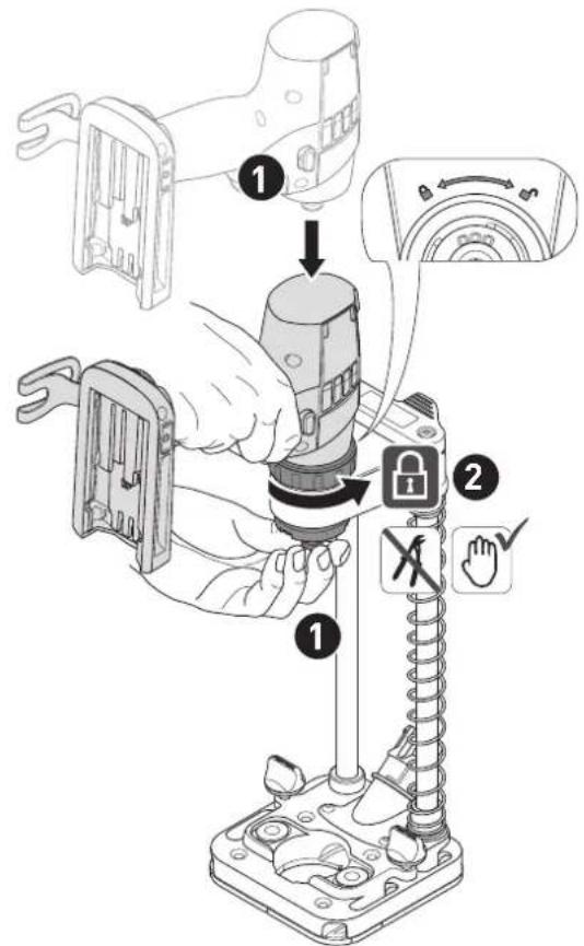
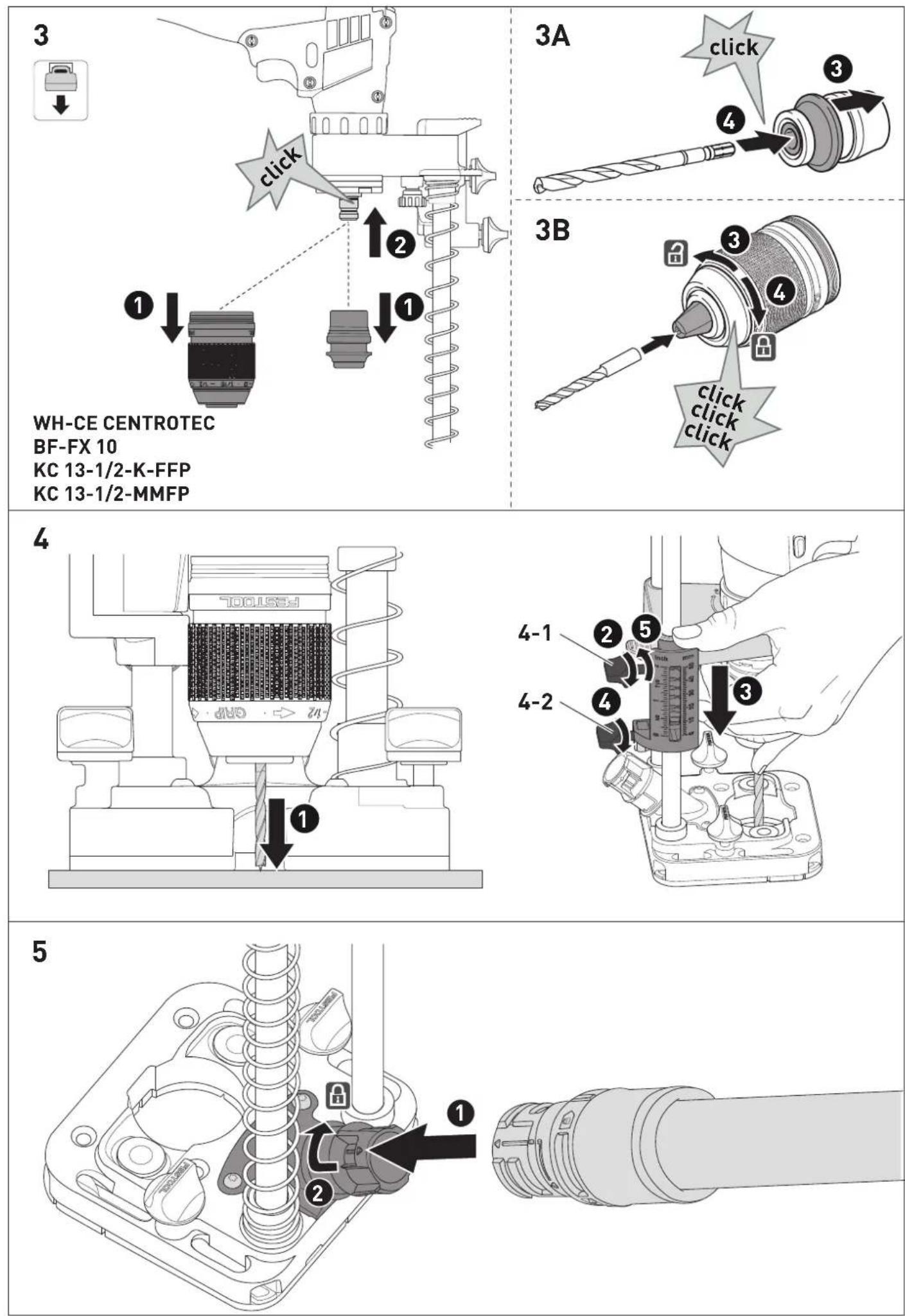
6.1 Fitting the power tool [2]
![FESTOOL MB 40 - Fitting the power tool [2] - 1](/content/2026/04/720692/images/22ad95221cfc770cf7ec9ea19d8862bbb00c9818ca281c77e2752d41dde17dc5.jpg)
WARNING
Risk of injury
Before using the mobile hole drilling attachment or transporting it with the power tool fitted, check that the lock nut is securely in place.
▶ Hold the drill spindle [1-8] in your hand and insert the power tool into the FastFix fixture.
▶ Tighten the lock nut [1-10] anti-clock-wise by hand.
6.2 Fitting attachments [3]
① Only fit the tool chuck and drill chuck with the power tool fitted.
Fitting the CENTROTEC tool chuck with the insertion tool [3A]
WARNING! Only clamp a CENTROTEC insertion tool in a CENTROTEC tool chuck.
Fitting the drill chuck with the insertion tool [3B]
WARNING! Clamp the insertion tool centrally in the chuck.
6.3 Setting the depth stop [4]
▶ Press the carriage down until the insertion tool makes contact with the workpiece.
▶ ② Tighten the upper rotary knob [4-1] clockwise to lock the carriage.
▶ Set the depth stop to the drilling depth using the scale, and hold the position.
▶ For the drilling depth with the lower rotary knob [4-2].
▶ Release the upper rotary knob [4-1] to release the carriage locking mechanism.
6.4 Dust extraction [5]
Comply with the safety regulations for dust that apply in your country. The relevant limit values must be adhered to at the workplace.
A dust extractor may be required for corresponding dust exposure and depending on regulations.
A Festool mobile dust extractor with a suction hose diameter of 27 mm (1-1/16") can be connected at the extractor connector.
▶ Attach the connecting sleeve of the extractor hose to the extractor connector of the mobile hole drilling attachment.
- Lock the bayonet fitting of the connecting sleeve as shown on the connecting sleeve.
CAUTION! Always use an antistatic suction hose (AS). A slight electric shock may cause you to panic briefly and become distracted, which may result in an accident.
7 Commissioning

WARNING
Risk of injury
- Remove the battery pack from the power tool before performing any work on the mobile hole drilling attachment.
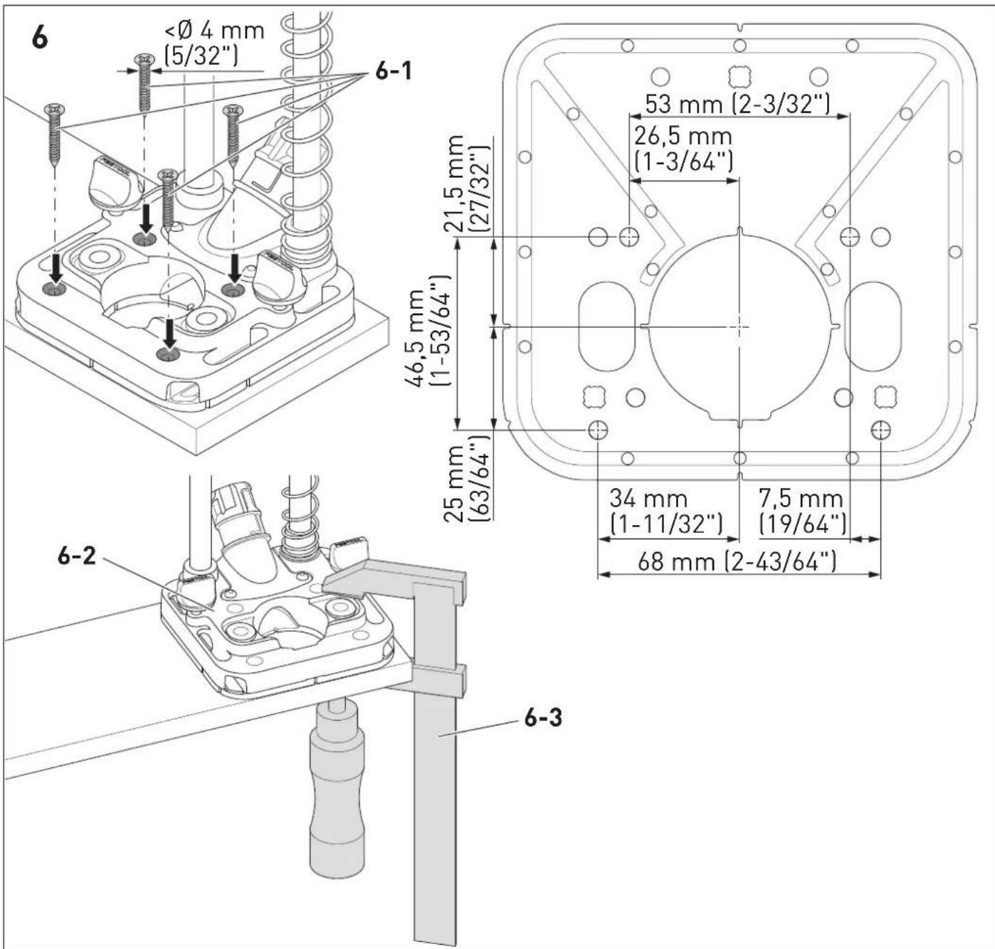
7.1 Fixing on the base [6]
The mobile hole drilling attachment can be fixed to the surface with screws [6-1] or using a fastening clamp [6-3] via the four holes in the base plate.
8 Working with the mobile hole drilling attachment

CAUTION
Risk of burns
The insertion tool may become very hot during operation.
▶ Wear gloves when replacing insertion tools.

WARNING
Risk of injury
▶ Always secure the workpiece in such a way that it cannot move during machining.
- Keep hands away from the rotating insertion tool.
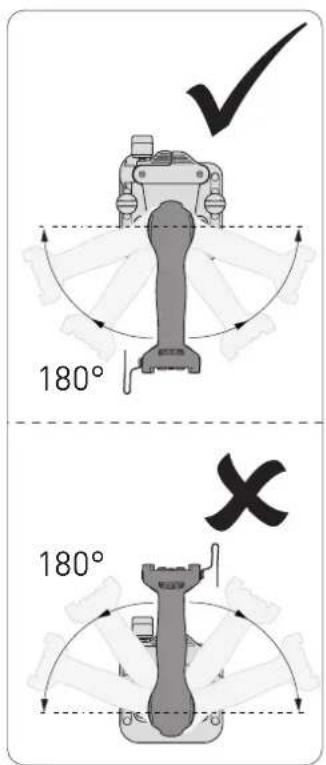
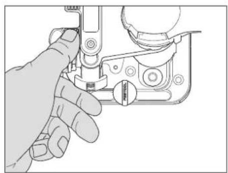
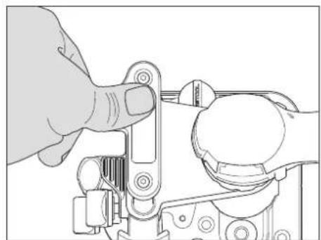
8.1 Holding the mobile hole drilling attachment correctly [7]
Only hold the mobile hole drilling attachment at the intended grip positions and holding positions [7].
Power tools with an installable additional handle or specified grip positions in two-handed operation must also be held there when using the mobile hole drilling attachment.
8.2 Drilling a hole
If the hole series function is not used, hole series pins [1-3] and [1-4] must be completely unscrewed and put to the side. The hole series pins can vibrate through the thread and lead to damage to sensitive surfaces.
▶ Press and hold the on/off switch on the power tool. Push the carriage down with one hand on the gripping surfaces or on the additional handle until it makes contact with the workpiece.
▶ Regulate the speed with the on/off switch and keep pressing the carriage down until it reaches the desired drilling depth.
- Slowly pull the carriage back up into the starting position and release the on/off switch.
8.3 Drilling on the base plate
▶ Use fastening clamps to fix the mobile hole drilling attachment to the centre of the base plate area [6-2] or use four screws to fix it to the base.
▶ Pre-position the workpiece on the base plate according to the scribe mark.
▶ Ensure that the workpiece is sufficiently held or fixed.
▶ Drill the hole.
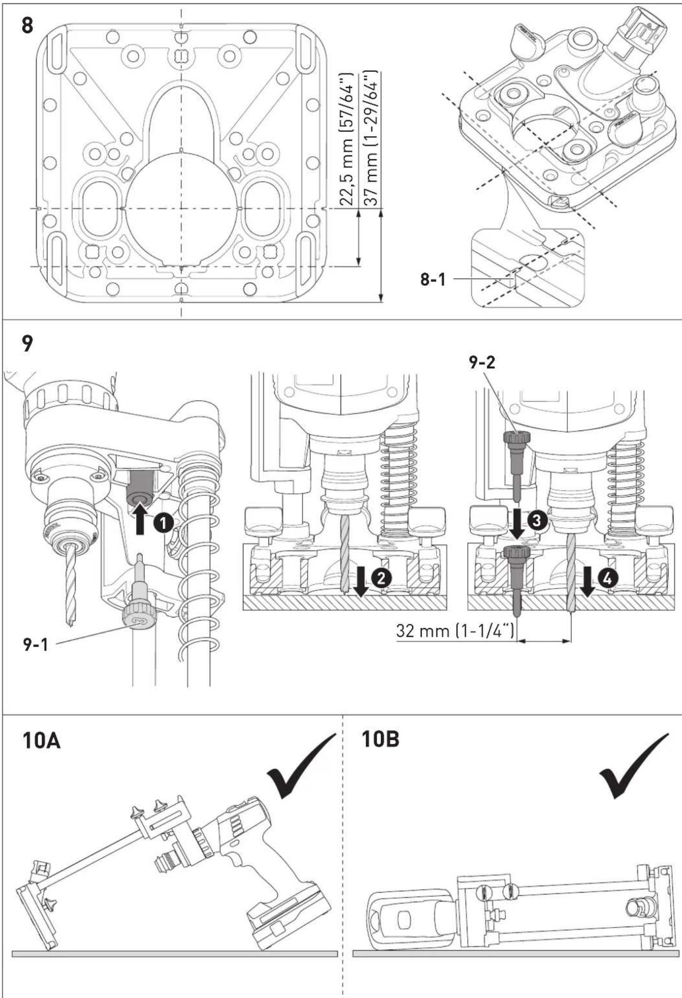
8.4 Drilling along the scribe mark [8]
The mobile hole drilling attachment has several positioning aids [8-1] that make it easier to pre-position the base plate.
- Align the mobile hole drilling attachment according to the drawn markings using the positioning aids [8-1].
▶ Drill the hole as described in section 8.2.
8.5 Drilling rows of holes [9]
The mobile hole drilling attachment enables the production of hole series with grid dimensions of 32 mm (1-1/4") at the original centre of the starting hole.
Use the parallel side fence or guide rail adapter to position the mobile hole drilling attachment with repeat accuracy.
- Screw the unneeded hole series pin [9-1] into the parking position on the carriage.
▶ Position the mobile hole drilling attachment and drill the first hole.
▶ Screw the hole series pin [9-2] fully into the guided threaded bush, and insert the mobile hole drilling attachment into the hole using the hole series pin.
▶ Doll the next hole with an offset.
8.6 After finishing work
Setting down the mobile hole drilling attachment [10A] & [10B]
▶ Put down the mobile hole drilling attachment with the power tool fitted in the parking position or on the side.
▶ Only store the mobile hole drilling attachment in a dry and frost-free environment.
9 Accessories
You can find the PO numbers for accessories and tools under www.festool.co.uk.
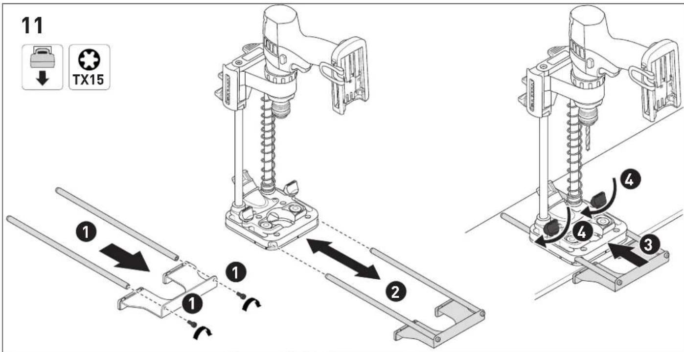
9.1 Parallel side fence [11]
▶ Insert the screws into the sheet metal and screw hand-tight with the rods.
▶ Side the parallel side fence into the base plate.
▶ Align the distance to the hole.
▶ For the position of the parallel side fence by hand using the rotary knobs.
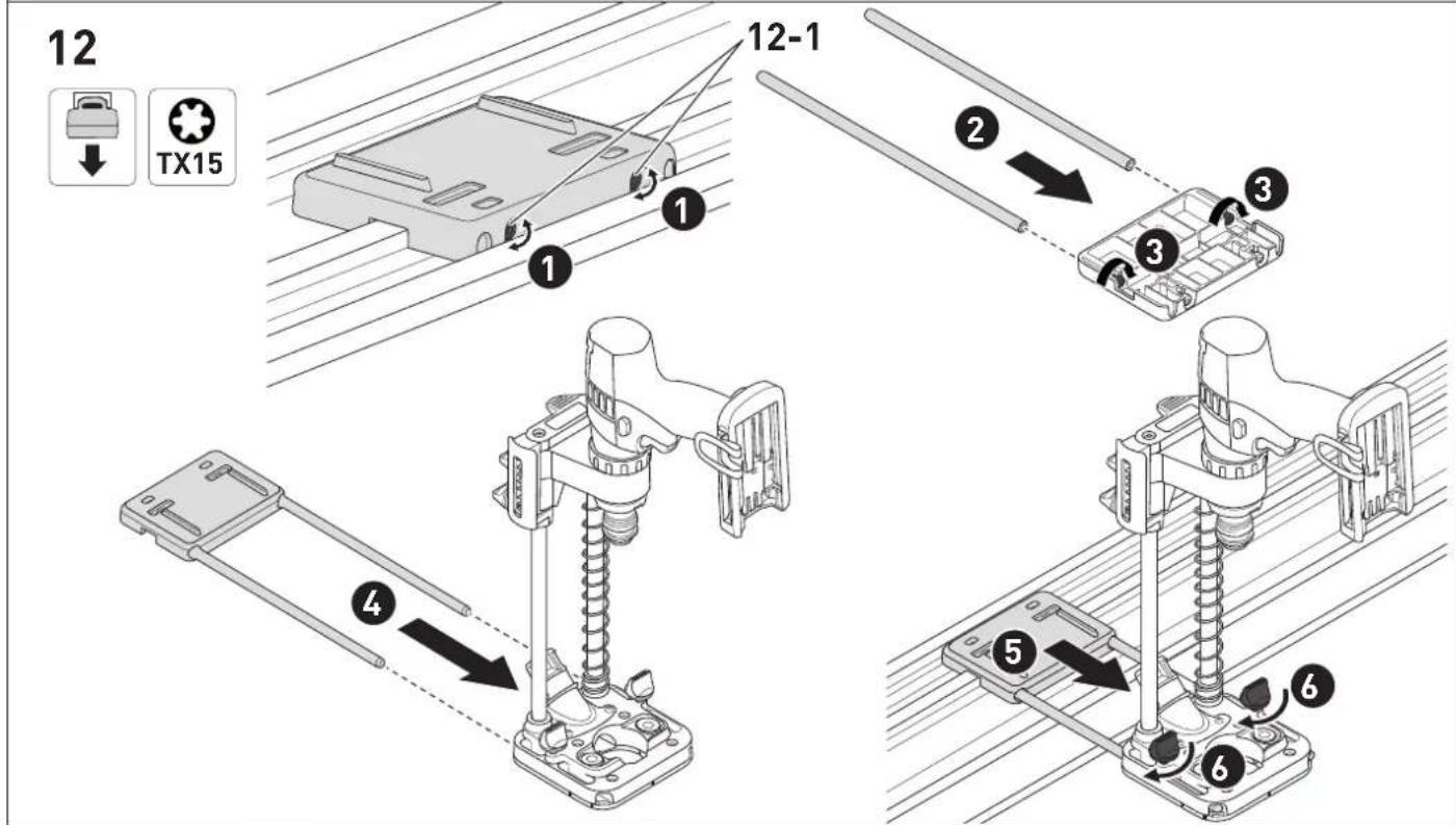
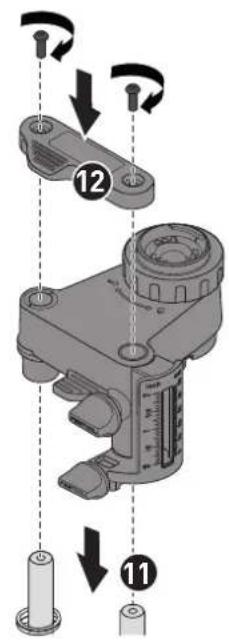
9.2 Guide rail adapter [12]
When using the guide rail adapter for the first time, adjust the guide play of the guide rail adapter once on the respective guide rail, using the adjustable jaws with the screws [12-1].
▶ ② Insert the rods into the guide rail adapter.
▶ Screw the screws to the rods hand-tight.
▶ Side the guide rail adapter into the base plate.
- Place the guide rail adapter on the guide rail and align the distance to the hole.
▶ F6 the position of the guide rail adapter by hand using the rotary knobs.
Do not clamp the guide rail adapter to the guide rail using the screws [12-1].
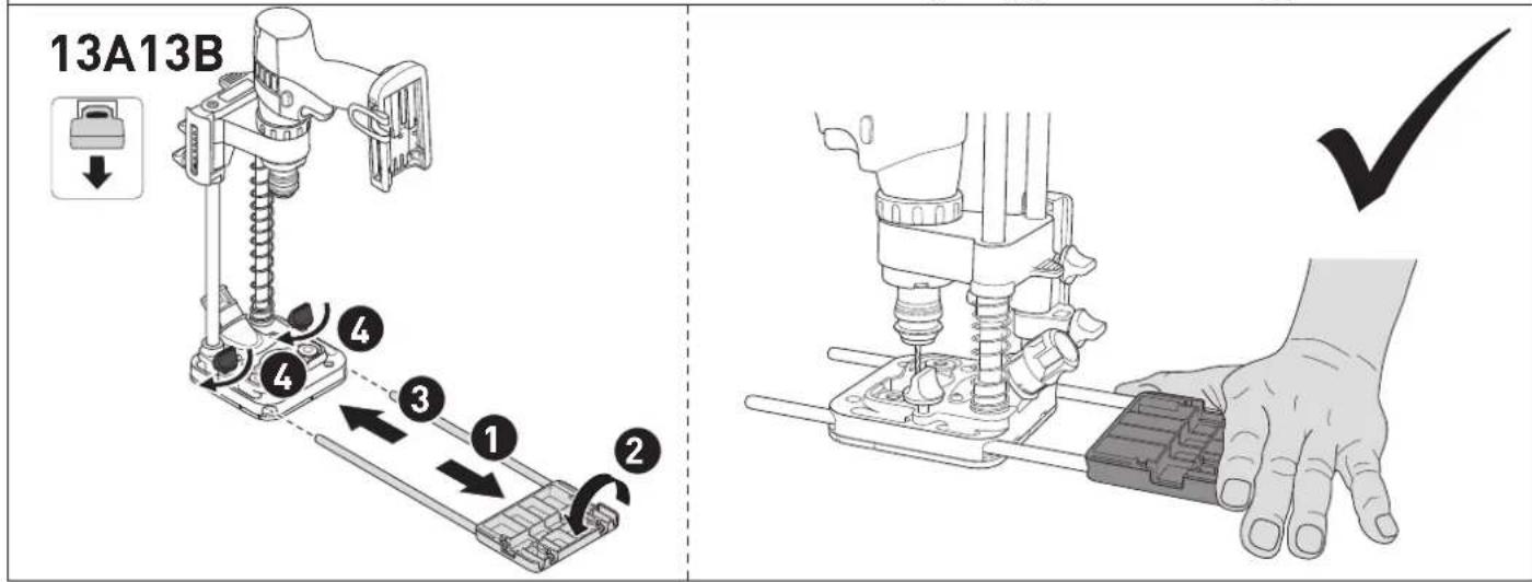
Using the guide rail adapter as tilt protection [13A]
Fit the power tool at a 90^ angle to the fence of the mobile hole drilling attachment, and set the guide rail adapter to the maximum distance.
▶ Remove the guide rail adapter from the base plate.
▶ Turn the guide rail adapter by 180°.
▶ Side the guide rail adapter into the base plate.
▶ Clamp the guide rail adapter with the two rotary knobs.
Using the guide rail adapter without the guide rail [13B]
For drills and percussion drills without an additional handle. The inverted guide rail adapter can also be used to increase the contact surface and as an additional handle.
During the drilling process, only hold the guide rail adapter at the intended grip position and holding position [13B].
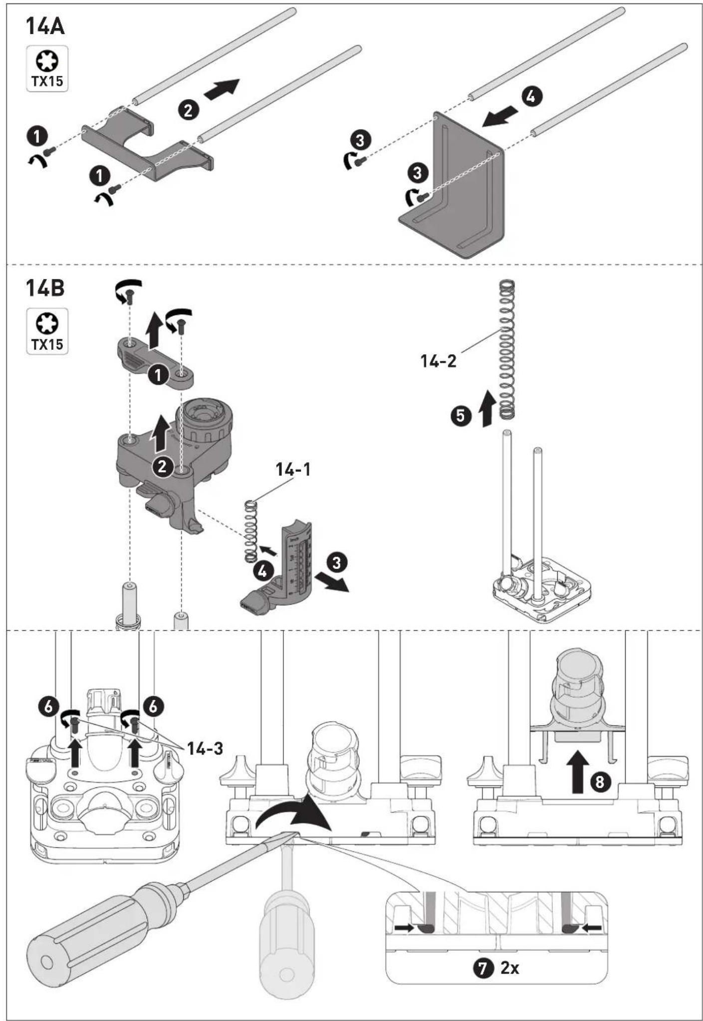
9.3 Fence for end face holes [14]
![FESTOOL MB 40 - Fence for end face holes [14] - 1](/content/2026/04/720692/images/4a26159b4039a4b6fab6fb5de7ded8852555fe5f4087a8c7015f2b91ea4dd89e.jpg)
WARNING
Risk of injury
The pressure spring [14-1] of the depth stop is prestressed and can spring out during removal.
▶ Wear protective goggles.
- Keep holding the pressure spring when removing the depth stop.
![FESTOOL MB 40 - The pressure spring [14-1] of the depth stop is prestressed and can spring out during removal. - 1](/content/2026/04/720692/images/51f1c294c307ab4f0d744761fdb10dac285d80be2a68a860b216654748885638.jpg)
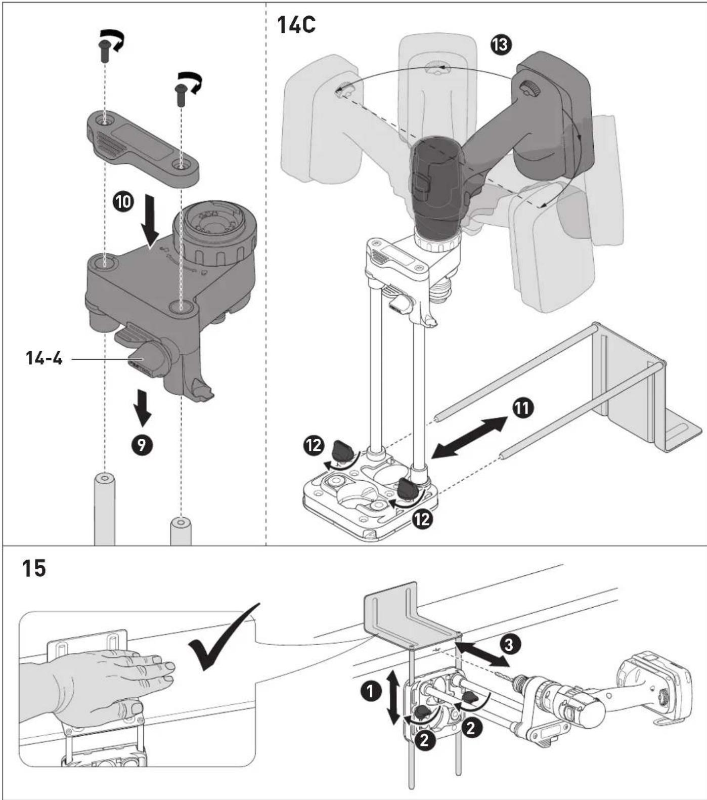
CAUTION
Risk of injury, risk of crushing
Unexpected and unintentional lowering of the carriage can crush your hand.
▶ Always fix the carriage with the rotary knob [14-4] when the pressure spring is removed.
Assembling the fence for end face holes [14A]
▶ Undo the screws and unscrew from the rods.
▶ Insert the screws into the sheet metal and screw hand-tight with the rods.
Converting the mobile hole drilling attachment for end face holes [14B]
▶ Undo the screws and remove the fence.
▶ Remove the carriage from the supports.
▶ Remove the depth stop from the carriage.
▶ Remove the pressure spring [14-1] from the depth stop.
▶ Remove the pressure spring [14-2] from the support.
▶ Undo the screws [14-3] on the extractor connector, press the snap hooks inwards with a slotted screwdriver.
▶ Remove the extractor connector and screw the screws [14-3] into the base plate to prevent them from being lost.
- Push the carriage, rotated by 180°, onto the supports and fix the position with the rotary knob [14-4].
Place the fence on the supports and screw in the screws hand-tight.
▶ ⑪ Slide the fence for end face holes into the base plate, and fix the position by hand using the rotary knobs ⑫.
▶ ⑬ Fit the power tool, see [14C].
English
WARNING! Other fitting positions can lead to your hand being crushed and to restricted operability.
Working with the fence for end face holes [15]

WARNING
Risk of injury
▶ Hold the fence at the permitted position [15].
▶ Pre-position the mobile hole drilling attachment at the scribe lines.
▶ Fix the position with the rotary knobs.
▶ Hold the fence for end face holes and drill the hole.
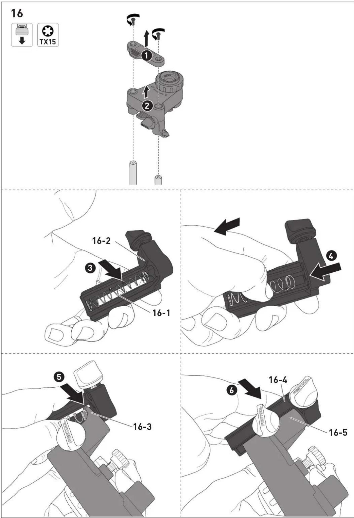
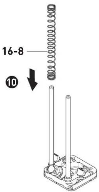
Dismantling the mobile hole drilling attachment [16]
▶ Udo the screws and remove the fence.
▶ Remove the carriage from the supports.
▶ Insert the pressure spring [16-1] into the housing of the depth stop [16-2].
▶ Press the pressure spring into the housing of the depth stop with your thumb. At the same time, pull the pressure spring back a little and hold it in position.
▶ Insert the holder [16-3] of the carriage between the housing of the depth stop and the retained pressure spring.
▶ Attach the housing of the depth stop [16-4] to the carriage [16-5].
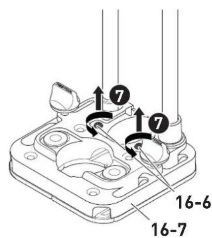
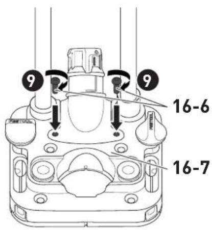
▶ Undo the screws [16-6] of the base plate [16-7].
▶ Side the extractor connector into the base plate mount.
▶ Screw the screws [16-6] into the base plate [16-7].
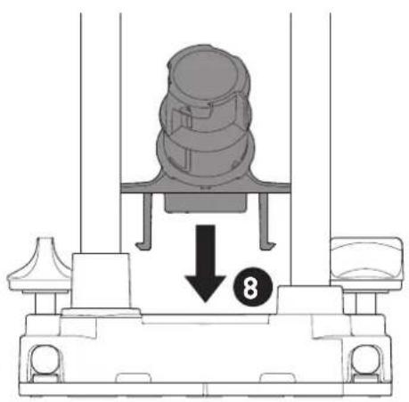
- Push the pressure spring [16-8] onto the support.
▶ 11 Push the carriage with the fitted depth stop onto the supports.
▶ 12 Place the fence on the supports and screw in the screws hand-tight.
10 Service and maintenance

WARNING
Risk of injury
- Remove the power tool before performing any maintenance and service work on the mobile hole drilling attachment.
Customer service and repairs must only be carried out by the manufacturer or service workshops. You must only use original Festool spare parts.
Further information: www.festool.co.uk/service Regularly remove dirt from the guides and contact surfaces with a cloth.
Only use Festool LFC 9022/50 cleaning and lubricating oil or oils with identical specifications in accordance with the manufacturer's instructions.
If the supports and carriages are stiff, apply a drop of cleaning and lubricating oil to each support and wipe with a clean cloth.
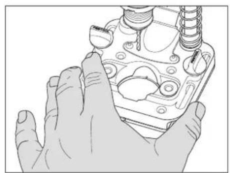
10.1 Replacing the lining [17]
▶ Undo and remove the screws.
▶ Remove the lining from the base plate and dispose of it.
▶ Place the new lining on the base plate.
- Screw the screws into the base plate and tighten by hand.
11 Environment
Do not dispose of the device in the household waste! Recycle devices, accessories and packaging. Observe applicable national regulations. Information on critical materials:
www.festool.co.uk/reach
12 Contact us
Imported into the UK by
Festool UK Ltd
1 Anglo Saxon Way
Bury St Edmunds
IP30 9XH
Great Britain
1 Symboles

[1-1] Plaque de base
[1-2] Revêtement
[1-11] Support FastFix
[1-12] Butée
[1-11] FastFix-holder
[1-12] anslag
8.5 Bore hullrekker [9]
niki TDC 18/4, C 18, T 18+3 (FastFix!), CXS 18, CXS 12, TXS 18, TXS 12 in akumulatorskim udarnim vrtalnim vijačnikom TPC 18/4 Festool.
![FESTOOL MB 40 - Bore hullrekker [9] - 1](/content/2026/04/720692/images/d12876fe982d007ec48e236c6a310aaa3bbd6c6e2a53d09d610a3e234e4db7cf.jpg)