
04-617 - Electric screwdriver NEO tools - Free user manual and instructions
Find the device manual for free 04-617 NEO tools in PDF.

| Product Type | Cordless Riveting Machine |
| Brand | NEO tools |
| Model | 04-617 |
| Supply Voltage | 18 V |
| Motor Type | Brushless |
| Compatible Rivet Diameters | 2.4 / 3.2 / 5.0 / 6.4 mm |
| Traction Power | 12,000 Nm |
| Aluminum Rivets | 2.0 to 6.4 mm |
| Stainless Steel Rivets | 2.0 to 5.0 mm |
| Stroke Length | 26 mm |
| Weight | 1.73 kg |
| Production Year | 2023 |
| Sound Pressure Level | 84.90 dB(A) |
| Sound Power Level | 92.90 dB(A) |
| Vibration Acceleration Value | 1.064 m/s² |
| Kit Contents | Riveting machine, 4 riveting nozzles, technical documentation |
| Integrated Protections | Overload and low voltage |
| Maintenance | Clean with a dry cloth; store in a dry place away from sunlight |
| Recommended Safety Equipment | Safety goggles, hearing protection, anti-vibration gloves |
Frequently Asked Questions - 04-617 NEO tools
User questions about 04-617 NEO tools
0 question about this device. Answer the ones you know or ask your own.
Ask a new question about this device
Download the instructions for your Electric screwdriver in PDF format for free! Find your manual 04-617 - NEO tools and take your electronic device back in hand. On this page are published all the documents necessary for the use of your device. 04-617 by NEO tools.
USER MANUAL 04-617 NEO tools
natural_image
Exterior view of a NEO TOOLS electric drill with visible branding and base (no text-heavy elements)04-617
A
C
natural_image
Technical line drawing of a mechanical component with no visible text or symbols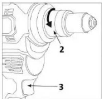
D
natural_image
Close-up of a black mechanical component with a hexagonal bolt (no visible text or symbols)1
natural_image
Close-up of a black cylindrical mechanical component with a hexagonal bolt inserted (no visible text or symbols)2
natural_image
Close-up of a black mechanical component with a cylindrical shaft and flange (no visible text or symbols)3
natural_image
Close-up of a metallic ring with concentric rings and central droplet (no text or symbols)4
PL INSTRUKCJA ORYGINALNA (OBSŁUGI)......4
EN TRANSLATION (USER) MANUAL 7

EN TRANSLATION (USER) MANUAL Cordless riveting machine: 04-617
NOTE: BEFORE USING THE EQUIPMENT, PLEASE READ THIS MANUAL CAREFULLY AND KEEP IT FOR FUTURE REFERENCE. PERSONS WHO HAVE NOT READ THE INSTRUCTIONS SHOULD NOT CARRY OUT ASSEMBLY, ADJUSTMENT OR OPERATION OF THE EQUIPMENT.
SPECIFIC SAFETY PROVISIONS
NOTE!
Read the operating instructions carefully, follow the warnings and safety conditions contained therein. The appliance has been designed for safe operation. Nevertheless: installation, maintenance and operation of the appliance can be dangerous. Following the following procedures will reduce the risk of fire, electric shock, injury and will reduce the installation time of the appliance
READ THE USER MANUAL CAREFULLY TO FAMILIARISE YOURSELF WITH THE APPLIANCE KEEP THIS MANUAL FOR FUTURE REFERENCE.
SAFETY RULES
General safety
Warning: when using power tools, basic safety precautions should always be followed to reduce the risk of fire, electric shock and injury. Read this manual in its entirety before operating the equipment. Keep the manual for future reference.
- Keep the work area clean. Cluttered work areas promote accidents.
- Consider the working environment. Do not expose tools to rain. Do not use tools in damp or wet areas. The work area should be well lit. Never use tools near flammable liquids or gases.
- Protect yourself against electric shock. Avoid body contact with earthed surfaces.
- Do not allow other persons. Do not allow other people, especially children, to approach the work area and touch the tool or power cord. Keep them away from the work area.
- Storage of unused tools. Store unused tools in a dry and closed place, out of the reach of children.
- Never use tools by force. Tools will be more efficient and safer when used at the rate for which they were intended.
Personal safety
- When operating a power tool, be alert, watch what you are doing and use common sense. Do not use power tools when you are tired or under the influence of drugs, alcohol or medication. A moment's inattention while operating a power tool can result in serious injury.
- Use personal protective equipment. Always wear safety goggles. Protective equipment such as dust mask, non-slip safety shoes, safety helmet, hearing protection, anti-vibration gloves used under appropriate conditions will reduce injuries.
- Prevention of accidental starting. Ensure that the switch is in the off position before connecting to the power supply and/or battery pack, picking up or moving the tool. Carrying power tools with your finger on the switch or switching on power tools with the switch on can lead to accidents.
- Remove the adjustable spanner or spanner before switching on the power tool. A spanner left in a moving part of the power tool can cause injury.
- Do not reach too high. Always maintain correct posture and balance. This allows better control of the power tool in unexpected situations.
- Dress appropriately. Do not wear loose clothing or jewellery. Keep hair, clothing and gloves away from moving parts. Loose clothing, jewellery or long hair can be pulled in by moving parts.
- If equipment is provided to connect dust extraction and collection equipment, ensure that it is connected and used correctly. The use of dust extraction can reduce dust-related hazards.
Safe use of power tools
- Do not use force. Use the correct power tool for the application. The right tool will do the job better and safer at the rate for which it was designed.
- Do not use a power tool if the switch does not turn it on and off. Any power tool that cannot be controlled by the switch is dangerous and must be repaired.
- Disconnect the plug from the power source and/or the battery pack from the power tool before making adjustments, changing accessories or storing the power tool. Such precautionary safety measures reduce the risk of accidentally starting the power tool.
- Store unused power tools out of the reach of children and do not allow anyone who is not familiar with the power tool or these instructions to operate them. Power tools are dangerous in the hands of untrained users.
PROPER BATTERY HANDLING AND OPERATION
- The battery charging process should be under the control of the user.
- Avoid charging the battery at temperatures below 0^ .
- Only charge the batteries with the charger recommended by the manufacturer. The use of a charger designed to charge a different type of battery poses a risk of fire.
- When the battery is not in use, keep it away from metal objects such as paper clips, coins, keys nails, screws, or other small metal items that can short-circuit the battery terminals. Short-circuiting the battery terminals can cause burns or fire.
- In the event of damage and/or misuse of the battery, gases may be released. Ventilate the room, consult a doctor in case of discomfort. The gases may damage the respiratory tract.
- Fluid leakage from the battery can occur in extreme conditions. Liquid leaking from the battery can cause irritation or burns. If a leak is detected, proceed as follows:
- Carefully wipe off the liquid with a piece of cloth. Avoid contact of the liquid with the skin or eyes.
- if the liquid comes into contact with the skin, the relevant area on the body should be washed immediately with copious amounts of clean water, or neutralise the liquid with a mild acid such as lemon juice or vinegar.
- if the liquid gets into the eyes, rinse them immediately with plenty of clean water for at least 10 minutes and seek medical advice.
- Do not use a battery that is damaged or modified. Damaged or modified batteries may act unpredictably, leading to fire, explosion or danger of injury.
- The battery must not be exposed to moisture or water.
- Always keep the battery away from a heat source. Do not leave it in a high temperature environment for long periods of time (in direct sunlight, near radiators or anywhere where the temperature exceeds 50°C).
- Do not expose the battery to fire or excessive temperatures. Exposure to fire or temperatures above 130^ may cause an explosion.
NOTE: A temperature of 130^ C can be specified as 265^ F.
- All charging instructions must be followed, and the battery must not be charged at a temperature outside the range specified in the rating table in the operating instructions. Charging incorrectly or at temperatures outside the specified range can damage the battery and increase the risk of fire.
BATTERY REPAIR:
- Do not repair defective batteries yourself. Repairs to the battery are only permitted by the manufacturer or an authorised service centre.
- The used battery should be taken to a disposal centre for this type of hazardous waste.
SAFETY INSTRUCTIONS FOR THE CHARGER
- The charger must not be exposed to moisture or water. The ingress of water into the charger increases the risk of shock. The charger may only be used indoors in dry rooms.
- Unplug the charger from the mains before carrying out any maintenance or cleaning.
- Do not use the charger placed on a flammable surface (e.g. paper, textiles) or in the vicinity of flammable substances. Due to the
temperature increase of the charger during the charging process, there is a danger of fire.
- Check the condition of the charger, cable and plug each time before use. If damage is found - do not use the charger. Do not attempt to disassemble the charger. Refer all repairs to an authorised service workshop. Improper installation of the charger may result in a risk of electric shock or fire.
- Children and physically, emotionally or mentally challenged persons, as well as other persons whose experience or knowledge is insufficient to operate the charger with all safety precautions, should not operate the charger without the supervision of a responsible person. Otherwise there is a danger that the device will be mishandled resulting in injury.
- When the charger is not in use, it should be disconnected from the mains.
- All charging instructions must be followed, and the battery must not be charged at a temperature outside the range specified in the rating data table in the operating instructions. Charging incorrectly or at temperatures outside the specified range can damage the battery and increase the risk of fire.
CHARGER REPAIR
- Do not repair a defective charger yourself. Repair of the charger is only permitted by the manufacturer or an authorised service centre.
- The used charger should be taken to a disposal centre for this type of waste.
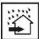
ATTENTION: The device is designed for indoor operation.
- Despite the use of an inherently safe design, the use of safety measures and additional protective measures, there is always a residual risk of injury during work.
- Li-Ion batteries can leak, catch fire or explode if they are heated to high temperatures or short-circuited. Do not store them in the car during hot and sunny days. Do not open the battery pack. Li-Ion batteries contain electronic safety devices which, if damaged, can cause the battery to catch fire or explode.
PICTOGRAMS AND WARNINGS

1

2

3

4

5
6
7
8

9
10
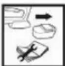
- Read the operating instructions, observe the warnings and safety conditions contained therein!
- Safety goggles should be worn to protect against loose particles that may be thrown up by the movement of the tool.
-
Hearing protectors should be worn. Exposure to noise can cause hearing loss
-
If dust is generated during work, wear a dust mask
- Wear anti-vibration or vibration-absorbing gloves
- Keep out of reach of children
- Disconnect from power supply before maintenance or repair
- Protect against moisture
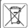
- Recyclable
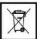
- Do not dispose of with household waste
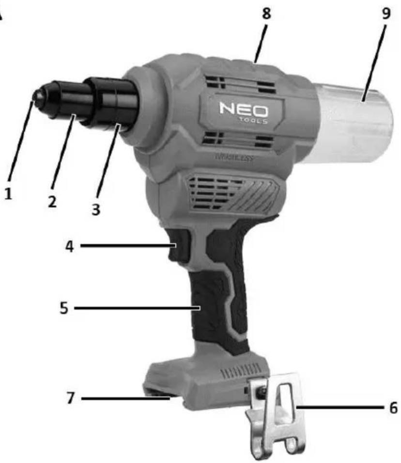
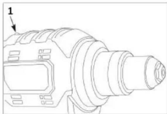
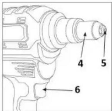
DESCRIPTION OF THE GRAPHIC ELEMENTS
The numbering below refers to the components of the device shown on the graphic pages of this manual.
| Designation | Description |
| 1 | Riveting bit |
| 2 | Bushing of the clamping mechanism |
| 3 | Knurled collar |
| 4 | Switch |
| 5 | Handle |
| 6 | Suspension bracket |
| 7 | Battery socket |
| 8 | Overload/discharge indicator light |
| 9 | Container for broken pins |
* There may be differences between the graphic and the actual product
PURPOSE
The riveting machine is a battery-powered power tool driven by a brushless motor. The riveting machine is used for riveting - joining two or more materials together by means of self-piercing rivets.
NOTE! Working instructions for the riveting tool
- Apply the power tool to the attachment before pressing the trigger.
- Hold the device securely. A high reaction moment may occur.
- Secure the workpiece. In a vise, the workpiece is held more securely than by hand.
- Always wait until the tool has come to a complete stop before putting it down.
- Do not grip the rivet during operation due to the risk of jamming when pulling the rivet.
USE
Connecting or disconnecting the battery
Connecting the battery: Align the alignment channels and insert the battery pack. Slide the battery pack until it locks into place with an audible "CLICK".
To remove the battery:
Press the red button on the front of the battery pack and slide out the battery pack.
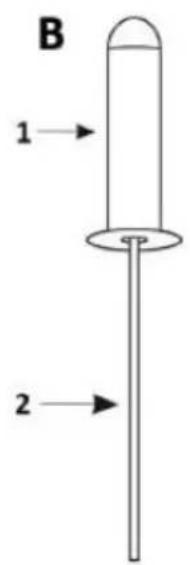
Rivet construction
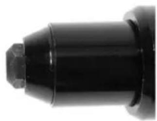
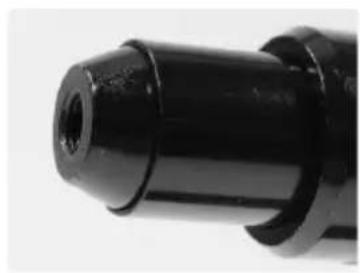
The rivet is made up of two parts: the rivet shank fig. B1 and the rod fig. B2. The bar, which is threaded through a mushroom-shaped head, terminating in a thickening with a diameter slightly larger than the inner diameter of the mandrel sleeve fig. B1. The riveting process consists of pulling the rod Fig. B2 with great force until it breaks away from the mandrel. As the bar is pulled out, the sleeve shortens clamping both sides of the material to be joined. The result is a durable and strong joint. The riveting tool can be used with rivets made of aluminium and steel with the diameters shown in the rating table.
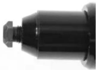
Nozzle size
When fixing the rivet, always use a nozzle/socket with the correct diameter fig. A1, which matches the shank diameter fig. B2 of the rivet size being used.
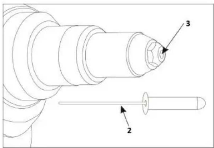
Tip replacement
STEP 1: Press and hold the device switch fig. B4; this will move the clamping mechanism inside the front sleeve fig. A2 to the rear position, ensuring that no pressure is applied to the tip fig. B3.
STEP 2: While still holding the switch in the depressed position, use the supplied spanner to replace the tip Fig. B3. Unscrew the bit that is currently installed. Screw in the bit with the diameter you will be working with, making sure the bit fig. B3 is fully tightened when reinstalled.
STEP 3: Release the switch. The device is now ready for use.
TOOL OPERATION
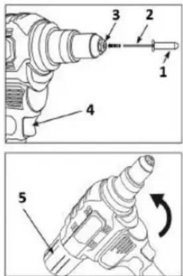
NOTE: The hole into which the rivet tip is inserted must be properly prepared in advance. Its diameter should be slightly larger than the diameter of the rivet pin. The mandrel must fit into it easily. However, it must be small enough so that the mandrel sleeve, when compressed, holds the joining materials firmly.
CAUTION: Do not place rivets in fingers when operating the unit, as this may cause injury due to jamming of the rivet.
Working with a riveting machine:
Insert the rivet shank fig. B2 into the end of the riveting pin fig. B3 and the other end of the riveting pin fig. B1 into the component to be riveted.
STEP 1: Press and hold the switch until the rivet is broken.
STEP 2: Release the switch fig. B4 until you hear the rivet being broken off. Depending on the rivet used, material and diameter, it may be necessary to work in two cycles. If the rivet pin does not break off in one working stroke, repeat the process until the pin breaks off.
STEP 3: Tilt the riveting device (backwards) so that the used mandrel falls into the mandrel collector Fig. B5 or forwards so that the mandrel can be removed from the front of the nozzle (manually).
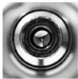
Overload protection:
If the battery is overloaded, the unit will stop working and the fault indicator Fig. C1 will light up red for 5 seconds. In this case, do not continue to press the switch. If the overload mode has been activated, to reset the riveting machine, unscrew the knurled collar fig. C2 and remove this part completely. Then press the switch fig. C3 to reset the mechanism to its normal state. Refit the knurled collar and continue use.
Low voltage protection:
If the battery voltage is too low for the riveting machine to operate, the machine will be switched off by the protective circuit and the failure indicator Fig. C1 will light up yellow for 10 seconds. In this case, recharge the battery or replace it with a battery with sufficient charge before continuing normal use.
ATTENTION! During long-term use, do not use the tool continuously while changing the battery pack. The tool needs time to cool down. At normal ambient temperatures this should take about 5 minutes, in hot operating conditions you should wait longer for the tool to cool down.
MAINTENANCE AND STORAGE
- This tool requires general lubrication or maintenance, just to keep it in good condition. In particular, make sure that the battery contacts are free of dust and dirt.
- Use only a dry, soft cloth or brush or a moderate stream of compressed air to clean the tool. Do not use a damp cloth, thinner, benzene etc. or other volatile solvents or strong detergents for cleaning.
- If the riveting machine is not used for a long period of time, the battery should be removed from the machine.
- Store the device in a dry and well-ventilated place, preferably in the factory packaging. Do not expose to direct and prolonged sunlight.
KIT CONTENTS:
| Riveting machine | 1pc. |
| Riveting inserts | 4pcs. |
| Technical documentation | 3pc |
| Rated data | |
| Supply voltage | 18V |
| Engine type | Brushless |
| Rivet diameter | 2.4/ 3.2/ 5.0/ 6.4 |
| Pulling power | 12000 Nm |
| Aluminium rivets | 2.0 6.4 |
| Stainless steel rivets | 2.0 5.0 |
| Stroke length | 26 mm |
| Mass | 1.73 kg |
| Year of production | 2023 |
| 04-617 indicates both the type and the designation of the machine | |
NOISE AND VIBRATION DATA
| Sound pressure level | Lp_A = 84.90 dB(A) K = 3 dB(A) |
| Sound power level | Lw_A = 92.90 dB(A) K = 3 dB(A) |
| Vibration acceleration values | a_h = 1.064 m/s2 K = 1.5 m/s2 |
Information on noise and vibration
The noise emission level of the equipment is described by: the emitted sound pressure level LpA and the sound power level LwA (where K denotes the measurement uncertainty). The vibrations emitted by the equipment are described by the vibration acceleration value ah (where K denotes the measurement uncertainty).
The emitted sound pressure level LpA, the sound power level LwA and the vibration acceleration value ah given in these instructions have been measured in accordance with IEC 62841-1. The vibration level ah given can be used to compare equipment and to make a preliminary assessment of vibration exposure.
The vibration level quoted is only representative of the basic use of the unit. If the unit is used for other applications or with other work tools, the vibration level may change. A higher vibration level will be influenced by insufficient or too infrequent maintenance of the unit. The reasons given above may result in increased vibration exposure during the entire working period.
In order to accurately estimate vibration exposure, it is necessary to take into account periods when the device is switched off or when it is switched on but not used for work. Once all factors have been accurately estimated, the total vibration exposure may turn out to be much lower.
In order to protect the user from the effects of vibration, additional safety measures should be implemented, such as cyclical maintenance of the machine and working tools, securing an adequate hand temperature and proper work organisation.
ENVIRONMENTAL PROTECTION
Electrically-powered products should not be disposed of with household waste, but should be taken to appropriate facilities for disposal. Contact your product dealer or local authority for information on disposal. Waste electrical and electronic equipment contains environmentally inert substances. Equipment that is not recycled poses a potential risk to the environment and human health.
"Grupa Topex Spółka z ograniczoną odpowiedzialnością" Spółka komandytowa with its registered office in Warsaw, ul. Pograniczna 2/4 (hereinafter: "Grupa Topex") informs that all copyrights to the content of this manual (hereinafter: "Manual"), including, among others. Its text, photographs, diagrams, drawings, as well as its composition, belong exclusively to Grupa Topex and are subject to legal protection under the Act of 4 February 1994 on Copyright and Related Rights (Journal of Laws 2006 No. 90 Poz. 631, as amended). Copying, processing, publishing, modifying for commercial purposes the entire Manual and its individual elements, without the consent of Grupa Topex expressed in writing, is strictly prohibited and may result in civil and criminal liability.
EC Declaration of Conformity
Manufacturer: Grupa Topex Sp. z o.o. Sp.k., Pograniczna 2/4 02-285 Warszawa
Product: 18V E+ riveting machine
Model: 04-617
Trade name: NEO TOOLS
Serial number: 00001 ÷ 99999
This declaration of conformity is issued under the sole responsibility of the manufacturer.
The product described above complies with the following documents:
Machinery Directive 2006/42/EC
Electromagnetic Compatibility Directive 2014/30/EU
RoHS Directive 2011/65/EU as amended by Directive 2015/863/EU And meets the requirements of the standards:
EN ISO 12100:2010; EN 62841-1:2015+A11; EN ISO 11148-1:2011; EN IEC 55014-1:2021; EN IEC 55014-2:2021;
EN IEC 63000:2018
This declaration relates only to the machinery as placed on the market and does not include components added by the end user or carried out by him/her subsequently.
Name and address of the EU resident person authorised to prepare the technical dossier:
Signed on behalf of:
Grupa Topex Sp. z o.o. Sp.k.
TOPEX GROUP Quality Officer
Warsaw, 2023-09-13
DE
INSTRUCTIUNI DE SIGURANTĂ PENTRU ÎNCĂRCĂTOR
OHUTUSJUHISED LAADIJA JAOKS
REPARATIE VAN ACCU'S:
WERKING VAN HET APPARAAT
Directive Machines 2006/42/CE

- EN TRANSLATION (USER) MANUAL Cordless riveting machine: 04-617
- SPECIFIC SAFETY PROVISIONS
- NOTE!
- READ THE USER MANUAL CAREFULLY TO FAMILIARISE YOURSELF WITH THE APPLIANCE KEEP THIS MANUAL FOR FUTURE REFERENCE.
- SAFETY RULES
- General safety
- Personal safety
- Safe use of power tools
- PROPER BATTERY HANDLING AND OPERATION
- NOTE: A temperature of 130° C can be specified as 265° F.
- BATTERY REPAIR:
- SAFETY INSTRUCTIONS FOR THE CHARGER
- CHARGER REPAIR
- ATTENTION: The device is designed for indoor operation.
- DESCRIPTION OF THE GRAPHIC ELEMENTS
- PURPOSE
- NOTE! Working instructions for the riveting tool
- USE
- Connecting or disconnecting the battery
- To remove the battery:
- Rivet construction
- Nozzle size
- Tip replacement
- TOOL OPERATION
- Working with a riveting machine:
- Low voltage protection:
- MAINTENANCE AND STORAGE
- Information on noise and vibration
- ENVIRONMENTAL PROTECTION
- EC Declaration of Conformity
- EN IEC 63000:2018
- DE
- INSTRUCTIUNI DE SIGURANTĂ PENTRU ÎNCĂRCĂTOR
- OHUTUSJUHISED LAADIJA JAOKS
- REPARATIE VAN ACCU'S:
- WERKING VAN HET APPARAAT
- Directive Machines 2006/42/CE
Brand : NEO tools
Model : 04-617
Category : Electric screwdriver