
04-715 - Grinder NEO tools - Free user manual and instructions
Find the device manual for free 04-715 NEO tools in PDF.

| Product Type | Angle Grinder (Grinder) |
| Brand | NEO tools |
| Model | 04-715 |
| Supply Voltage | 230-240 V AC |
| Frequency | 50 Hz |
| Rated Power | 3000 W |
| No-load Speed | 6600 min⁻¹ |
| Max. Disc Diameter | 230 mm |
| Disc Bore | 22.2 mm |
| Spindle Thread | M14 |
| Weight | 5.55 kg |
| Protection Class | II |
| IP Protection Rating | IPX0 |
| Main Functions | Grinding, cutting, sanding, brushing |
| Auxiliary Handle | Yes, mountable in two positions |
| Disc Guard | Tool-free adjustable |
| Soft Start | Yes |
| Safety Stop in Case of Blockage | Yes, automatic restart after unblocking |
| Maintenance | Cleaning with dry cloth, compressed air; replacement of carbon brushes by a professional |
| Repairability | Spare parts available via authorized service center; replaceable power cord |
| Supplied Accessories | Blade guard, special wrench, auxiliary handle, self-tightening outer flange |
| Intended Use | Grinding, cutting, sanding and brushing work on metals, stone, etc. (dry only) |
| General Information | Production year 2023; compliant with EU directives; do not dispose with household waste |
Frequently Asked Questions - 04-715 NEO tools
User questions about 04-715 NEO tools
0 question about this device. Answer the ones you know or ask your own.
Ask a new question about this device
Download the instructions for your Grinder in PDF format for free! Find your manual 04-715 - NEO tools and take your electronic device back in hand. On this page are published all the documents necessary for the use of your device. 04-715 by NEO tools.
USER MANUAL 04-715 NEO tools
natural_image
Exterior view of a NEO TOOLS electric tool with visible blade and grip (no text or symbols on the tool body)04-715


natural_image
Line drawing of a person using a radial workpiece on a workbench (no text or symbols)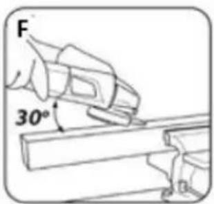

natural_image
Line drawing of a robotic arm gripping a mechanical component (no text or symbols)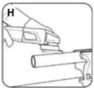
natural_image
Technical line drawing of a mechanical assembly with no visible text or symbolsPL INSTRUKCJA ORYGINALNA (OBSŁUGI) 5
EN TRANSLATION (USER) MANUAL....9
DE ÜBERSETZUNG (BENUTZERHANDBUCH) 13
RU РУКОВОДСТВО ПО ПЕРЕВОДУ (РУКОВОДСТВО ПОЛЬЗОВАТЕЛЯ)....18
HU FORDÍTÁSI (FELHASZNÁLÓI) KÉZIKÖNYV 22
RO MANUAL DE TRADUCERE (UTILIZATOR) 26
UA ПОСІБНИК З ПЕРЕКЛАДУ (КОРИСТУВАЧА)...... 31
CZ PŘEKLAD (UŽIVATELSKÉ) PŘÍRUČKY.... 35
SK PREKLAD (POUŽÍVATEL'SKEJ) PRÍRUČKY ...... 39
SL PREVOD (UPORABNIŠKI) PRIROČNIK 43
LT VERTIMO (NAUDOTOJO) VADOVAS 47
LV TULKOŠANAS (LIETOTĀJA) ROKASGRĀMATA 51
EE TÖLKIMISE (KASUTAJA) KÄSIRAAMAT 55
BG ПРЕВОД (РЪКОВОДСТВО ЗА ПОТРЕБИТЕЛЯ)...... 59
HR PRIRUČNIK ZA PRIJEVOD (KORISNIK) 64
SR ПРИРУЧНИК ЗА ПРЕВОЂЕЊЕ (КОРИСНИК)...... 67
GR ΕΓΧΕΙΡΪΔΙΟ ΜΕΤΑΦΡΑΣΗΣ (ΧΡΗΣΤΗ)...... 71
ES MANUAL DE TRADUCCIÓN (USUARIO).... 76
IT MANUALE DI TRADUZIONE (UTENTE) 81
NL VERTICALING (GEBRUIKERS)HANDLEIDING.... 85
PT MANUAL DE TRADUÇÃO (UTILIZADOR)....89
FR MANUEL DE TRADUCTION (UTILISATEUR).... 94
PL INSTRUKCJA ORYGINALNA (OBSŁUGI) SZLIFIERKA KĄTOWA 04-715
UWAGA: PRZED PRZYSTĄPIENIEM DO UŻYTKOWANIA ELEKTRONARZĘDZIA NALEŻY UWAŻNIE PRZECZYTAĆ NINIEJSZĄ INSTRUKCJĘ I ZACHOWAĆ JĄ DO DALSZEGO WYKORZYSTANIA.
SZCZEGÓŁOWE PRZEPISY BEZPIECZEŃSTWA

EN TRANSLATION (USER) MANUAL
ANGLE GRINDER 04-715
NOTE: READ THIS MANUAL CAREFULLY BEFORE USING THE POWER TOOL AND KEEP IT FOR FUTURE REFERENCE.
SPECIFIC SAFETY PROVISIONS
Safety tips for sanding, grinding with sandpaper, working with wire brushes and cutting with a grinding wheel.
- This power tool can be used as a regular sander, a sandpaper sander, a wire brush sander and as an abrasive cutter. Follow all safety instructions, instructions, descriptions and data supplied with the power tool. Failure to comply with the following may create a risk of electric shock, fire and/or serious injury.
- This power tool must not be used for polishing. Use of the power tool for other than the intended work activity may result in hazards and injuries.
- Do not use an accessory that is not specifically designed and recommended by the manufacturer for the tool. The fact that an accessory can be fitted to a power tool is no guarantee of safe use.
- The permissible speed of the working tool used must not be less than the maximum speed indicated on the power tool. A work tool rotating faster than the permissible speed may break and parts of the tool may splinter.
- The outer diameter and thickness of the working tool must correspond to the dimensions of the power tool. Work tools with incorrect dimensions cannot be sufficiently shielded or inspected.
- Work tools with a threaded insert must fit exactly onto the thread on the spindle. For flange-mounted work tools, the diameter of the work tool bore must match the diameter of the flange. Work tools that cannot fit exactly on the power tool will rotate unevenly, vibrate very strongly and may cause loss of control of the power tool.
- Under no circumstances should damaged work tools be used. Inspect the tooling before each use, e.g. grinding wheels for chipping and cracking, sanding pads for cracking, wear or heavy wear, wire brushes for loose or broken wires. If a power tool or work tool has fallen, check it for damage or use another undamaged tool. If the tool has been checked and fixed, the power tool should be switched on to its highest speed for one minute, taking care that the operator and bystanders in the vicinity are out of the zone of the rotating tool. Damaged tools usually break during this testing time.
- Personal protective equipment must be worn. Depending on the type of work, wear a protective mask covering the entire face, eye protection or safety goggles. If necessary, use a dust mask, hearing protection, protective gloves or a special apron to protect against small particles of abraded and machined material. Protect
your eyes from airborne foreign bodies generated during work. A dust mask and respiratory protection must filter out dust produced during work. Noise exposure over a prolonged period, can lead to hearing loss.
- Ensure that bystanders are at a safe distance from the power tool's reach zone. Anyone in the vicinity of a working power tool must use personal protective equipment. Workpiece splinters or broken work tools can splinter and cause injury even outside the immediate reach zone.
- When carrying out work where the tool could come into contact with concealed electrical wires or its own power cable, hold the tool only by the insulated surfaces of the handle. Contact with the mains lead may result in voltage being transmitted to metal parts of the power tool, which could cause an electric shock.
- Keep the mains cable away from rotating work tools. If you lose control of the tool, the mains cable could be cut or pulled in and your hand or whole hand could get caught in a rotating work tool.
- Never put the power tool down before the working tool has come to a complete stop. A rotating tool may come into contact with the surface on which it is put down, so you could lose control of the power tool.
- Do not carry a power tool while it is in motion. Accidental contact of clothing with the rotating power tool may cause it to be pulled in and the power tool to drill into the operator's body.
- Clean the ventilation slots of the power tool regularly. The motor blower draws dust into the housing and a large accumulation of metal dust can cause an electrical hazard.
- Do not use the power tool near flammable materials. Sparks may ignite them.
- Do not use tools that require liquid coolants. The use of water or other liquid coolants can lead to electric shock.
Rejection and relevant safety tips
Kickback is the sudden reaction of a power tool to the blockage or obstruction of a rotating tool such as a grinding wheel, sanding pad, wire brush, etc. The snagging or blocking leads to a sudden stop of the rotating work tool. An uncontrolled power tool will thus be jerked in the direction opposite to the direction of rotation of the working tool.
When, for example, the grinding wheel jams or becomes jammed in the workpiece, the power supply to the power tool is switched off. When the wheel regains the ability to rotate, the grinder starts to work automatically. The movement of the grinding wheel (towards or away from the operator) is then dependent on the direction of movement of the wheel at the point of blockage. In addition to this, grinding wheels can also break. Kickback is the consequence of improper or incorrect use of the power tool. It can be avoided by taking the appropriate precautions described below.
- The power tool should be held firmly, with the body and hands in a position to soften the recoil. If an auxiliary handle is included as part of the standard equipment, it should always be used in order to have the greatest possible control over the recoil forces or the recoil moment at start-up. The operator can control the jerk and recoil phenomena by taking appropriate precautions.
- Never hold hands near rotating work tools. The working tool may injure the hand due to recoil.
- Keep away from the range zone where the power tool will move during recoil. As a result of recoil, the power tool moves in the opposite direction to the movement of the grinding wheel at the point of blockage.
- Be particularly careful when machining corners, sharp edges, etc. Prevent work tools from being deflected or becoming jammed. A rotating work tool is more susceptible to jamming when machining angles, sharp edges or if it is kicked back. This can become a cause of loss of control or kickback.
- Do not use wood or toothed discs. Work tools of this type often cause recoil or loss of control of the power tool.
Special safety instructions for grinding and cutting with a grinding wheel
- Only use a grinding wheel designed for the power tool and a guard designed for the wheel. Grinding wheels that are not tooling for the particular power tool cannot be sufficiently shielded and are not sufficiently safe.
- Bent sanding discs must be mounted in such a way that no part of the disc protrudes beyond the edge of the protective cover. An
improperly fitted grinding disc protruding beyond the edge of the protective cover cannot be sufficiently protected.
- The guard must be firmly attached to the power tool to guarantee the greatest possible degree of safety and positioned so that the part of the grinding wheel exposed and facing the operator is as small as possible. The guard protects the operator from splinters, accidental contact with the grinding wheel, as well as sparks that could ignite clothing.
- The grinding wheel must only be used for the work intended for it. Never, for example, grind with the side surface of a cut-off wheel. Cut-off wheels are designed to remove material with the edge of the disc. The effect of lateral forces on these grinding wheels may break them.
- Always use undamaged clamping flanges of the correct size and shape for the selected grinding wheel. Proper flanges support the grinding wheel and thus reduce the danger of the wheel breaking. Flanges for cut-off wheels may differ from those for other grinding wheels.
- Do not use used grinding wheels from larger power tools. Grinding wheels for larger power tools are not designed for the higher RPM that is a characteristic of smaller power tools and may therefore break.
Additional specific safety instructions for grinding wheel cutting
- Avoid jamming of the cutting disc or too much pressure. Do not make excessively deep cuts. Overloading the cutting disc increases its load and its tendency to jam or block and thus the possibility of discarding or breaking.
- Avoid the area in front of and behind the rotating cutting disc. Moving the cutting disc in the workpiece away from you may cause the power tool to fly off with the rotating disc directly towards you in the event of a kickback.
- Plates or large objects should be supported before machining to reduce the risk of kickback caused by a jammed disc. Large workpieces may bend under their own weight. The workpiece should be supported on both sides, both near the cutting line and at the edge.
- Take special care when cutting holes in walls or operating in other invisible areas. The cutting disc plunging into the material may cause the tool to recoil if it encounters gas pipes, water pipes, electrical cables or other objects.
Special safety instructions for sanding with sandpaper
Do not use oversized sheets of sandpaper. When selecting the sanding paper size, follow the manufacturer's recommendations. Sanding paper protruding beyond the sanding plate can cause injury and can lead to the paper becoming blocked or torn, or to recoil.
Special safety instructions for working with wire brushes
- It should be taken into account that even with normal use, there is a loss of pieces of wire through the brush. Do not overload the wires by applying too much pressure. Airborne pieces of wire can easily pierce through thin clothing and/or skin.
- If a guard is recommended, prevent the brush from coming into contact with the guard. The diameter of plate and pot brushes can be increased by pressure and centrifugal forces. Additional safety tips
- On tools designed to accept threaded grinding wheels, check that the length of the grinding wheel thread is appropriate to the length of the spindle thread.
- The workpiece must be secured. Clamping the workpiece in a clamping device or vise is safer than holding it in your hand.
- Do not touch the cutting and grinding discs before they have cooled down.
- When using a quick-action flange, ensure that the inner flange fitted to the spindle is fitted with a rubber O-ring and that this ring is not damaged. Also ensure that the surfaces of the outer flange and inner flange are clean.
- Use the quick-action flange only with abrasive and cutting discs. Use only undamaged and properly functioning flanges.
ATTENTION: The device is designed for indoor operation.
Despite the use of an inherently safe design, the use of safety measures and additional protective measures, there is always a residual risk of injury during work.
Explanation of the pictograms used.

- Caution Take special precautions
- Read the operating instructions, observe the warnings and safety conditions contained therein!
- Wear personal protective equipment (safety goggles, ear protection)
4.Wear protective gloves
5.Disconnect the power cord before servicing or repairing. - Keep children away from the tool
- Protect from rain
- Protection class two
Additional safety features
In the event of a temporary mains power failure or after removing the plug from the power socket with the switch in the "on" position, the switch must be unlocked and set to the off position before restarting.
As an additional feature to increase user safety, the power supply to the grinder is cut off when the machine is overloaded or the disc is blocked. When the disc regains the ability to rotate, the grinder will automatically start working.
ATTENTION: Pay close attention at all times when working with the angle grinder so as not to miss this moment.
CONSTRUCTION AND APPLICATION
The angle grinder is a class II insulated hand-held power tool. The machine is driven by a single-phase commutator motor, the speed of which is reduced via a geared angle gear. It can be used for both grinding and cutting. This type of power tool is widely used for removing all types of burrs from the surface of metal parts, surface treatment of welds, cutting through thin-walled pipes and small metal parts, etc. With the appropriate accessories, the angle grinder can be used not only for cutting and grinding, but also for cleaning e.g. rust, paint coatings, etc.
Its areas of use include a wide range of repair and construction work not only related to metals. The angle grinder can also be used to cut and grind building materials, e.g. brick, paving stones, ceramic tiles, etc.
The appliance is intended for dry use only, not for polishing. Do not misuse the power tool
Misuse.
Do not handle materials containing asbestos. Asbestos is carcinogenic.
Do not work with materials whose dusts are flammable or explosive. When working with the power tool, sparks are generated which may ignite the vapours emitted.
Cut-off wheels must not be used for grinding work. Cut-off wheels work with the side face and grinding with the front face of such a wheel may cause damage to the wheel resulting in a risk of personal injury to the operator.
DESCRIPTION OF THE GRAPHIC PAGES
The numbering below refers to the components of the unit shown on the graphic pages of this manual.
- Spindle lock button
2.Switch - Additional handle
4.Shield
5.Self-clamping outer flange
6,Inner flange
7.Interlock button to prevent accidental start-up
- Carbon brush cover
9.Main handle lock
- Lever (blade guard)
* There may be differences between the drawing and the product.
ACCESSORIES
• Shield 1 pc.
• Special spanner 1 pc.
• Additional handle 1 pc.
• Self-clamping external flange 1pc.
PREPARATION FOR WORK
FITTING AN AUXILIARY HANDLE
The auxiliary handle (3) is installed in one of the holes on the grinder head. The use of a sander with an auxiliary handle is recommended. If you hold the sander with both hands while working (also using the auxiliary handle), there is less risk of your hand touching the rotating disc or brush and being injured by kickback.
ADJUSTABLE MAIN HANDLE
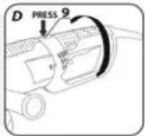
Before starting work, the position of the main grinder handle can be adjusted to be most convenient for the work to be performed. The handle can be adjusted to 3 positions by turning it 90^ to the left or right in relation to the basic position.
- Press the main handle locking button (9)
- Rotate the main handle to the desired position.
- The main handle automatically locks into the selected position.
INSTALLATION AND ADJUSTMENT OF THE SHIELD
The blade guard protects the operator from debris, accidental contact with the work tool or sparks. It should always be fitted with extra care taken to ensure that its covering part faces the operator.
The design of the blade guard attachment allows tool-free adjustment of the guard to the optimum position.
- Loosen and pull back the lever (10) on the disc guard (4).
- Rotate the disc guard (4) to the desired position.
- Lock by lowering the lever(10).
- Removing and adjusting the disc guard is done in reverse order to its installation.
TOOL REPLACEMENT
Work gloves must be worn during tool changing operations.
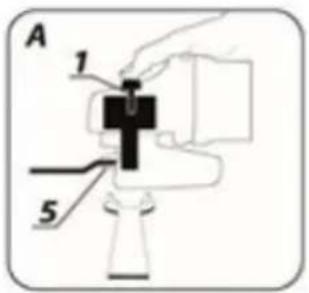
The spindle lock button (1) is only to be used to lock the spindle of the grinder when mounting or dismounting the work tool. It must not be used as a brake button while the disc is spinning. Doing so may damage the grinder or injure the user.
DISC MOUNTING
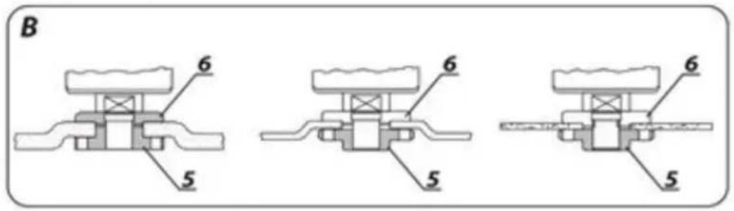
In the case of grinding or cutting discs with a thickness of less than 3 mm, the self-locking nut of the outer flange (5) must be screwed on flat on the disc side.
• Press the spindle lock button (1).
- Tighten the self-clamping external flange (5) by hand.
- Loosen and remove the self-locking outer flange (5).
- Place the disc so that it is pressed against the surface of the inner flange (6).
- Screw on self-locking external flange (5)
Dismantling of the discs is carried out in the reverse order to assembly. During assembly, the disc should be pressed against the surface of the inner flange (6) and seated centrally on its underside. If the self-locking nut becomes jammed, use a special spanner.
INSTALLATION OF WORKING TOOLS WITH THREADED HOLE WANY
Press the spindle lock button (1).
- Remove the previously mounted implement - if fitted.
- Remove both flanges before installation - inner flange (6) and self-clamping outer flange (5).
- Screw the threaded part of the working tool onto the spindle and tighten slightly.
Disassembly of threaded bore working tools is in reverse order to assembly.
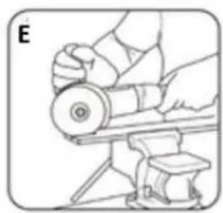
MOUNTING OF ANGLE GRINDER IN ANGLE GRINDER STAND
It is permissible to use the angle grinder in a dedicated tripod for angle grinders, provided it is fitted correctly in accordance with the tripod manufacturer's assembly instructions.
Check the condition of the grinding wheel before using it. Do not use chipped, cracked or otherwise damaged grinding wheels. A worn wheel or brush should be replaced immediately with a new one before use. When you have finished working, always switch off the grinder and wait until the working tool has come to a complete standstill. Only then can the sander be put away. Do not brake the rotating grinding wheel by pressing it against the workpiece.
- Never overload the grinder. The weight of the power tool exerts sufficient pressure to operate the tool effectively. Overloading and excessive pressure can cause the power tool to break dangerously.
- If the sander falls during operation, it is essential to inspect and, if necessary, replace the working tool if it is found to be damaged or deformed.
- Never strike the work tool against the work material.
- Avoid bouncing and scraping with the disc, especially when working on corners, sharp edges, etc. (this can cause loss of control and kickback). (this may result in loss of control of the power tool and a kickback effect).
- Never use discs designed for cutting wood from circular saws. The use of such saw blades often results in a recoil phenomenon of the power tool, loss of control and can lead to injury to the operator.
ON/OFF
Hold the sander with both hands during start-up and operation.
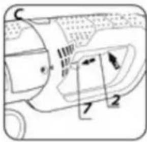
The sander is equipped with a safety switch to prevent accidental start-up.
- Push the lever button (7) forwards.
- Press the on/off button (2).
- Releasing pressure on the switch button (2) stops the grinder.
During start-up, the engine starts with a slow start, which is used to start the unloaded engine.
After starting the grinder, wait until the grinding wheel has reached maximum speed before starting work. The switch must not be operated while the sander is switched on or off. The sander switch may only be operated when the power tool is away from the workpiece.
CUTTING
• Cutting with an angle grinder can only be done in a straight line.
- Do not cut the material while holding it in your hand.
- Large workpieces should be supported and care should be taken that the support points are close to the cutting line and at the end of the material. Material placed stably will not tend to move during cutting.
- Small workpieces should be clamped e.g. in a vice, using clamps, etc. The material should be clamped so that the cutting point is close to the clamping element. This will ensure greater cutting precision.
- Do not allow vibration or tamping of the cutting disc, as this will impair the quality of the cut and may cause the cutting disc to break.
- No lateral pressure should be exerted on the cutting disc during cutting.
- Use the correct cutting disc depending on the material to be cut.
- When cutting through material, it is recommended that the direction of feed is in line with the direction of rotation of the cutting disc.
The depth of cut depends on the diameter of the disc.
- Only discs with nominal diameters no larger than those recommended for the grinder model should be used.
- When making deep cuts (e.g. profiles, building blocks, bricks, etc.), do not allow the clamping flanges to come into contact with the workpiece.
Cutting discs reach very high temperatures during operation - do not touch them with unprotected parts of the body before they have cooled down.
SANDING
Grinding work can be carried out using e.g. grinding discs, cup wheels, flap discs, discs with abrasive fleece, wire brushes, flexible discs for sandpaper, etc. Each type of disc and workpiece requires a suitable working technique and the use of appropriate personal protective equipment.
Discs designed for cutting should not be used for sanding.
Grinding discs are designed to remove material with the edge of the disc.
- Do not grind with the side of the disc. The optimum working angle for this type of disc is 30^ .
-
Grinding work must only be carried out using grinding discs suitable for the material.
When working with flap discs, abrasive fleece discs and flexible discs for sandpaper, care must be taken to ensure the correct angle of attack. -
Do not sand with the entire surface of the disc.
• These types of discs are used for machining flat surfaces.
Wire brushes are mainly intended for cleaning profiles and hard-to-reach areas. They can be used to remove e.g. rust, paint coatings, etc. from the material surface.
Only work tools whose permissible speed is higher than or equal to the maximum speed of the angle grinder without load should be used.
Unplug the power cord from the mains socket before carrying out any installation, adjustment, repair or operation.
MAINTENANCE AND STORAGE
- It is recommended to clean the device immediately after each use.
- Do not use water or other liquids for cleaning.
- The unit should be cleaned with a dry piece of cloth or blown with low-pressure compressed air.
- Do not use any cleaning agents or solvents, as these may damage the plastic parts.
- Clean the ventilation slots in the motor housing regularly to prevent the unit from overheating.
- If the power cable is damaged, it must be replaced with a cable of the same characteristics. This operation should be entrusted to a qualified specialist or have the appliance serviced.
• Always store the device in a dry place out of the reach of children.
Any faults should be rectified by an authorised manufacturer's service.
TECHNICAL SPECIFICATIONS
RATING DATA
| PARAMETER | VALUE |
| Supply voltage | 230-240 V AC |
| Supply frequency | 50 Hz |
| Rated power | 3000 W |
| Rated speed | 6600 min ^-1 |
| Max. disc diameter | 230 mm |
| Internal disc diameter | 22.2 mm |
| Spindle thread | M14 |
| IP degree of protection | IPX0 |
| Protection class | II |
| Mass | 5.55 kg |
| Year of production | 2023 |
| NOISE AND VIBRATION DATA | |
| Sound pressure level (grinding) | LPA = 91 dB(A) K=3dB(A) |
| Sound pressure level (cutting) | L_PA = 90 dB(A) K=3dB(A) |
| Sound power level (grinding) | L_WA = 99 dB(A) K=3dB(A) |
| Sound power level (cutting) | L_WA = 98 dB(A) K=3dB(A) |
| Maximum acceleration value | a_h = 8 m/s^2 K=1.5 m/s^2 |
NOISE AND VIBRATION DATA
Information on noise and vibration
The levels of emitted noise, such as the emitted sound pressure level Lp_A and the sound power level Lw_A and the measurement uncertainty K, are given below in the instructions in accordance with EN 60745.
Vibration values (acceleration value) a _h and measurement uncertainty K determined in accordance with EN60745 are given below.
The vibration level given in this manual has been measured in accordance with the measurement procedure specified by EN60745 and can be used to compare power tools. It can also be used for a preliminary assessment of vibration exposure.
The vibration level indicated is representative of the basic use of the power tool. If the power tool is used for other applications or with other work tools, and if it is not sufficiently maintained, the vibration level may change. The reasons given above may result in increased vibration exposure throughout the working period.
To accurately estimate vibration exposure, it is necessary to take into account periods when the power tool is switched off or when it is switched on but not used for work. In this way, the total exposure to vibration may turn out to be much lower.
Additional safety measures should be put in place to protect the user from the effects of vibration, such as: maintenance of the power tool and working tools, securing an appropriate hand temperature, proper work organisation.
ENVIRONMENTAL PROTECTION
Electrically-powered products should not be disposed of with household waste, but should be taken to appropriate facilities for disposal. Contact your product dealer or local authority for information on disposal. Waste electrical and electronic equipment contains environmentally inert substances. Unrecycled equipment poses a potential risk to the environment and human health.
"Grupa Topex Spółka z ograniczoną odpowiedzialnością" Spółka komandytowa with its registered office in Warsaw, ul. Pograniczna 2/4 (hereinafter: "Grupa Topex") informs that all copyrights to the content of this manual (hereinafter: "Manual"), including, among others. Its text, photographs, diagrams, drawings, as well as its composition, belong exclusively to Grupa Topex and are subject to legal protection under the Act of 4 February 1994 on Copyright and Related Rights (Journal of Laws 2006 No. 90 Poz. 631, as amended). Copying, processing, publishing, modifying for commercial purposes the entire Manual and its individual elements, without the consent of Grupa Topex expressed in writing, is strictly prohibited and may result in civil and criminal liability.
EC Declaration of Conformity
Manufacturer: Grupa Topex Sp. z o.o. Sp.k., ul. Pograniczna 2/4 02-285 Warsaw
Product: Angle grinder
Model: 04-715
Trade name: NEO TOOLS
Serial number: 00001 ÷ 99999
This declaration of conformity is issued under the sole responsibility of the manufacturer.
The product described above complies with the following documents:
Machinery Directive 2006/42/EC
Electromagnetic Compatibility Directive 2014/30/EU
RoHS Directive 2011/65/EU as amended by Directive 2015/863/EU
And meets the requirements of the standards:
EN 62841-1:2015+A11:2022; EN IEC 62841-2-3:2021+A11:2021
EN IEC 55014-1:2021; EN IEC 55014-2:2021; EN IEC 61000-3-
2:2019+A1:2021; EN 61000-3-3:2013+A1:2019+A2:2021; EN IEC 63000:2018
This declaration relates only to the machinery as placed on the market and does not include components
added by the end user or carried out by him/her subsequently.
Name and address of the EU resident person authorised to prepare the technical dossier:
Signed on behalf of:
Grupa Topex Sp. z o.o. Sp.k.
TOPEX GROUP Quality Officer
Warsaw, 2023-12-19
DE
1
2
3
4

5
6
7
8
5.Self-clamping külsö karima
6, belső karima
9.Main mâner principal de blocare
VERTALING (GEBRUIKERS)HANDLEIDING
HAAKSE SLIJPMACHINE 04-715
OPMERKING: LEES DEZE HANDLEIDING ZORGVULDIG DOOR VOORDAT U HET ELEKTRISCHE APPARAAT GEBRUIKT EN BEWAAR DE HANDLEIDING VOOR TOEKOMSTIG GEBRUIK.
SPECIFIEKE VEILIGHEIDSVOORSCHRIFTEN
INSTALLATIE VAN WERKGEREEDSCHAP MET DRAADGAT WANY
Product: Haakse slijper
Model: 04-715
REPLACEMENT D'OUTILS
DONNÉES D'ÉVALUATION
Directive Machines 2006/42/CE


- PL INSTRUKCJA ORYGINALNA (OBSŁUGI) SZLIFIERKA KĄTOWA 04-715
- UWAGA: PRZED PRZYSTĄPIENIEM DO UŻYTKOWANIA ELEKTRONARZĘDZIA NALEŻY UWAŻNIE PRZECZYTAĆ NINIEJSZĄ INSTRUKCJĘ I ZACHOWAĆ JĄ DO DALSZEGO WYKORZYSTANIA.
- SZCZEGÓŁOWE PRZEPISY BEZPIECZEŃSTWA
- EN TRANSLATION (USER) MANUAL
- ANGLE GRINDER 04-715
- NOTE: READ THIS MANUAL CAREFULLY BEFORE USING THE POWER TOOL AND KEEP IT FOR FUTURE REFERENCE.
- SPECIFIC SAFETY PROVISIONS
- Rejection and relevant safety tips
- Special safety instructions for grinding and cutting with a grinding wheel
- Additional specific safety instructions for grinding wheel cutting
- Special safety instructions for sanding with sandpaper
- Special safety instructions for working with wire brushes
- ATTENTION: The device is designed for indoor operation.
- Additional safety features
- CONSTRUCTION AND APPLICATION
- Misuse.
- DESCRIPTION OF THE GRAPHIC PAGES
- ACCESSORIES
- PREPARATION FOR WORK
- FITTING AN AUXILIARY HANDLE
- ADJUSTABLE MAIN HANDLE
- INSTALLATION AND ADJUSTMENT OF THE SHIELD
- TOOL REPLACEMENT
- DISC MOUNTING
- INSTALLATION OF WORKING TOOLS WITH THREADED HOLE WANY
- MOUNTING OF ANGLE GRINDER IN ANGLE GRINDER STAND
- ON/OFF
- CUTTING
- SANDING
- MAINTENANCE AND STORAGE
- NOISE AND VIBRATION DATA
- Information on noise and vibration
- ENVIRONMENTAL PROTECTION
- EC Declaration of Conformity
- Machinery Directive 2006/42/EC
- Electromagnetic Compatibility Directive 2014/30/EU
- RoHS Directive 2011/65/EU as amended by Directive 2015/863/EU
- EN 62841-1:2015+A11:2022; EN IEC 62841-2-3:2021+A11:2021
- EN IEC 55014-1:2021; EN IEC 55014-2:2021; EN IEC 61000-3-
- 2:2019+A1:2021; EN 61000-3-3:2013+A1:2019+A2:2021; EN IEC 63000:2018
- DE
- VERTALING (GEBRUIKERS)HANDLEIDING
- HAAKSE SLIJPMACHINE 04-715
- SPECIFIEKE VEILIGHEIDSVOORSCHRIFTEN
- INSTALLATIE VAN WERKGEREEDSCHAP MET DRAADGAT WANY
- REPLACEMENT D'OUTILS
Brand : NEO tools
Model : 04-715
Category : Grinder