
58G030 - Grass trimmer Graphite - Free user manual and instructions
Find the device manual for free 58G030 Graphite in PDF.

User questions about 58G030 Graphite
0 question about this device. Answer the ones you know or ask your own.
Ask a new question about this device
Download the instructions for your Grass trimmer in PDF format for free! Find your manual 58G030 - Graphite and take your electronic device back in hand. On this page are published all the documents necessary for the use of your device. 58G030 by Graphite.
USER MANUAL 58G030 Graphite
natural_image
Line drawing of a mechanical lever device (no text or symbols on the diagram itself)PL PODKASZARKA AKUMULATOROWA
EN CORDLESS GRASS TRIMMER
DE AKKU-RASENTRIMMER
RU АККУМУЛЯТОРНЫЙ ТРИММЕР
UA ТРИМЕР АКУМУЛЯТОРНИЙ
HU AKKUMULÁTOROS FÜKASZA
RO TRIMMER CU ACUMULATOR
©Z AKUMULÁTOROVÝ VYŽÍNAČ
SK AKUMULÁTOROVÝ VYŽÍNAČ
SL AKUMULATORSKA KOSILNICA
LT AKUMULIATORINĖ ŽOLIAPJOVĖ (TRIMERIS)
LV AKUMULATORA TRIMMERIS
AKUMULATORA TRIMMERIS
BG АКУМУЛАТОРЕН ТРИМЕР ЗА ТРЕВА
HR AKUMULATORSKI TRIMER ZA TRAVU
SR AKUMULATORSKI TRIMER
ΕΠΑΝΑΦΟΡΤΙΖΟΜΕΝΟ ΧΟΡΤΟΚΟΠΤΙΚΟ
ES DESBROZADORA A BATERÍA
IT TAGLIABORDI A BATTERIA
NL ACCU GRASTRIMMER
FR TAILLE-HERBES À BATTERIE
10* LAT DOSTĘPNOŚCI CZĘŚCI ZAMIENNYCH

INSTRUKCJA ORYGINALNA
(OBSŁUGI)
PODKASZARKA AKUMULATOROWA
58G030
UWAGA: PRZED PRZYSTĄPIENIEM DO UŻYTKOWANIA URZĄDZENIA NALEŻY UWAŻNIE PRZECZYTAĆ NINIEJSZĄ INSTRUKCJĘ I ZACHOWAĆ JĄ DO DALSZEGO WYKORZYSTANIA.
SZCZEGÓŁOWE PRZEPISY BEZPIECZEŃSTWA
WYMAGANIA SZCZEGÓŁOWE DLA PRZYCINAREK TRAWNIKOWYCH (PODKASZAREK) ZASILANYCH AKUMULATOREM


TRANSLATION OF THE ORIGINAL INSTRUCTIONS CORDLESS GRASS TRIMMER 58G030
CAUTION: BEFORE USING THE DEVICE READ THIS MANUAL CAREFULLY AND KEEP IT FOR FUTURE REFERENCE.
DETAILED SAFETY REGULATIONS
DETAILED REQUIREMENTS FOR BATTERY POWERED GRASS TRIMMERS
WARNING: Observe safety regulations when using the grass trimmer. For your own and other persons safety read this manual before starting to work with the grass trimmer. Please keep this manual for future reference.
- This garden tool is not intended for use by persons with restricted physical, sensory or mental capabilities (including children) or persons who have no experience or are unfamiliar with the tool, unless the use is supervised or carried out in accordance with equipment use instructions handed over by persons responsible for their safety.
- REMEMBER. Operator or user is responsible for any accident or emerging hazards to other persons or surrounding.
Preparation
- When cutting, always wear sturdy shoes and long trousers.
- Always use personal protection equipment, such as protective glasses and earmuff protectors.
- Carefully check the terrain where you plan to work, remove all objects that might get projected by rotating cutting line.
- Make sure the grass trimmer head is not damaged before each use.
- Hold the grass trimmer with both hands and keep the head axis perpendicular to the ground.
Use
- Cut grass only in daylight or well illuminated places.
- Avoid cutting wet grass.
- Always ensure you stand firmly on the ground. Be careful on sloped ground not to lose your balance.
- Walk, never run.
- Do not hand the garden tool over to children or persons who are not familiar with this manual.
- Stop working when there are bystanders, children or animals in immediate vicinity.
- Cut only crosswise a slope, never up or down.
- Be very careful when changing direction of cutting.
- Switch off the motor when carrying the grass trimmer.
- Do not use the grass trimmer with damaged shields, body or without supplied shields.
- Make sure your feet are away from cutting line and switch on the motor as described in the manual.
- Do not tilt the grass trimmer when switching on.
- Never install metal cutting parts.
- Be careful not to cut yourself with the device for cutting line length adjustment.
- Make sure the ventilation holes are free from obstructions.
- Make sure you hold the grass trimmer firmly with both hands before starting up the grass trimmer.
- Never keep your hands or feet close to moving parts.
- Only authorised persons should repair the grass trimmer.
- Use only spare parts recommended by the manufacturer.
- Maintenance and storage
- Keep all components in good condition to ensure the grass trimmer works safely.
- To keep the operation safe, replace worn out or damaged parts.
- Protect the grass trimmer against moisture.
- Keep the tool beyond reach of children.
- Use only cutting lines of appropriate type.
Safety instructions for battery
- In case of battery damage and improper use it may produce gas. Ventilate room and seek medical attention in case of medical symptoms. Gas can damage respiratory tract.
- Improper operation conditions may lead to battery electrolyte leak, avoid contact with the substance. In case of accidental contact, flush the electrolyte abundantly with water. In case of contact with eyes, additionally seek medical attention. Leaked electrolyte may cause eye irritation or burns.
- Do not disassemble the battery – there is a risk of short circuiting.
- Do not use power tool battery in rain.
- Always keep the battery away from sources of heat. Do not leave the battery for a long time in high temperature (in direct sunlight, in proximity of heaters and wherever the temperature exceeds 50^ ).
Safety instructions for battery charger
- This equipment is not intended for use by persons with restricted physical, sensory or mental capabilities (including children) or persons who have no experience or are unfamiliar with the equipment, unless the use is supervised or carried out in accordance with equipment use instructions handed over by persons responsible for their safety.
- Pay attention to children so they don't play with the equipment.
- Do not expose the charger to humidity or water. Ingress of water into the charger increases risk of electric shock. Use the charger only in dry rooms.
- Disconnect the charger from power supply before starting any maintenance or cleaning.
- Do not use the charger when placed on flammable surface (e.g. paper, textiles) or in proximity of flammable substance. Greater charger temperature when charging increases risk of fire.
- Check condition of the charger, cable and plug before each use. Do not use the charger if any damage is found. Do not try to disassemble the charger. All repairs should be made at an authorised service workshop. Improper charger assembly may cause electric shock or fire.
- Children or persons who are physically, emotionally or mentally disabled and other persons, whose experience or knowledge is insufficient to use the charger while following all safety rules should not use the charger without supervision of person responsible for their safety. Otherwise there is a risk of improper use and injuries in consequence.
When the charger is not in use, it should be disconnected from the mains network.
CAUTION! The design is assumed to be safe, protection measures and additional safety systems are used, nevertheless there is always a small risk of injuries at work.
Li-lon batteries may leak, set on fire or explode when heated to high temperature or short-circuited. Do not store the batteries in a car in hot and sunny days. Do not open the battery. Li-lon batteries contain electronic protection devices that, if damaged, may cause fire or explosion of the battery.
Explanation of used symbols

1234

6


7

8
5

6

7
8
9
1011
[Non-Text]

12

1314
15

16

1718


1920
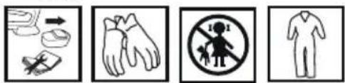
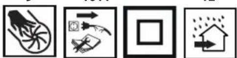
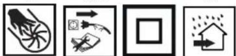
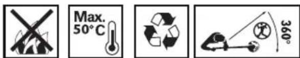
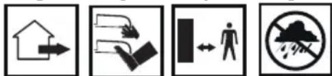
- CAUTION! Use precaution measures.
2,3. Read instruction manual, observe warnings and safety conditions therein! - Use personal protection equipment (protective goggles, earmuff protectors).
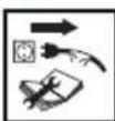
- Remove the battery from the device before starting any adjustments or cleaning related tasks.
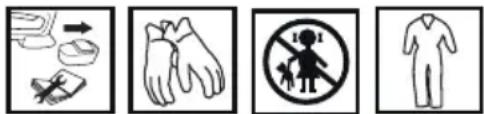
- Use protective gloves.
- Keep the tool away from children.
- Use protective clothes.
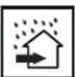
- The garden tool is designed for outdoors use
- Do not put your hands or legs close to cutting parts!
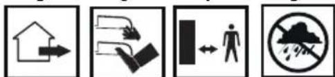
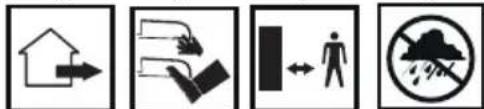
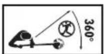
- Keep safe distance from working garden tool
- Protect the tool from moisture.
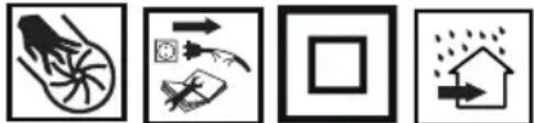
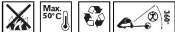
- When the device is operating do not put hands into its openings
- Disconnect the charger before repairs.
- Protection class 2.
- The charger is designed to operate indoors in dry environment.
- Do not throw cells into fire.
- Maximum permissible cell temperature.
- Recycling.
- Do not allow other persons in the grass trimmer operation range.
CONSTRUCTION AND USE
Cordless grass trimmer is a battery-powered tool. The drive consists of DC commutator motor with permanent magnets. Tool of this type is designed for tasks in home garden. The grass trimmer is designed for trimming grass in corners and edges of lawns and flowerbeds, wherever lawn mower cannot reach.

Use the power tool in accordance with the manufacturer's instructions only.
DESCRIPTION OF DRAWING PAGES
Below enumeration refers to the device elements depicted on the drawing pages of this manual.
-
Edge rod
-
Locking ring for telescopic pipe
-
Locking knob for auxiliary handle
-
Auxiliary handle
-
Switch
-
Switch lock button
-
Main handle
-
Spare cutting parts
-
Telescopic pipe
-
Locking button for head tilt angle
-
Guard
-
Cutting part
-
Head
-
Battery lock button
-
Battery
-
Charger
-
LED diodes
-
Button for battery level indication
-
Battery level indicator (LED)
-
Guard attachment screws
-
Spindle
-
Pin
* Differences may appear between the product and drawing.
MEANING OF SYMBOLS

CAUTION

WARNING

ASSEMBLY / SETTINGS

INFORMATION
EQUIPMENT AND ACCESSORIES
| 1. Guard | - | 1 | pce | |
| 2. Head with cutting parts | - 1 pce | |||
| 3. Cutting parts | - | 20 | pcs | |
| 4. Screws | - | 2 | pcs | |
| 5. Screw | - | 1 | pce |
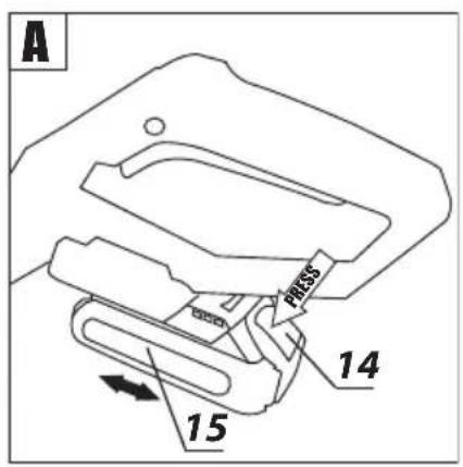
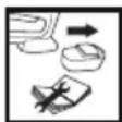
REMOVING AND INSERTING THE BATTERY

- Push the battery lock button (14) and slide out the battery (15) (fig. A).
- Insert charged battery (15) into the handle holder, you should hear when the battery lock button (14) snaps.
BATTERY CHARGING

The battery for the device is supplied partially charged. Charge the battery in ambient temperature between 4°C and 40°C. New battery, or one that has not been used for a long time, will reach full efficiency after approximately 3 to 5 charge/discharge cycles.

- Remove the battery (15) from the device (fig. A).
• Connect the charger to mains socket (230 V AC).
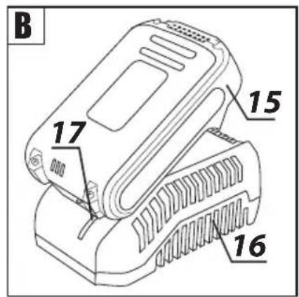
- Slide the battery (15) into the charger (16) (fig. B). Make sure the battery is properly fitted (pushed to the end).

When the charger is connected to a mains socket (230 V AC), the green diode (17) on the charger turns on to indicate connected supply.
When the battery (15) is placed in the charger (16), the red diode (17) on the charger turns on to indicate that the charging is in progress. At the same time green diodes (19) of the battery level indication are flashing in different configurations, see description below.
- All diodes are flashing – the battery is empty and requires charging.
- 2 diodes are flashing – the battery is partially discharged.
- 1 diode is flashing – the battery level is high.

Once the battery is charged, the diode (17) on the charger lights green, and all battery level diodes (19) light continuously. After some time (approx. 15 s) the battery level indication diodes (19) turn off.
Do not charge the battery for more than 8 hours. Exceeding this time limit may cause damage to battery cells. The charger does not turn off automatically when the battery is full. Green diode on the charger will remain on. Battery level indication diodes turn off after some time. Disconnect power supply before removing the battery from the charger socket. Avoid consecutive short chargings. Do not charge the battery after short use of the tool. Significant decrease of the period between chargings indicates the battery is worn out and should be replaced.

Batteries heat up when charging. Do not operate just after charging – wait for the battery to cool down to room temperature. It will prevent battery damage.
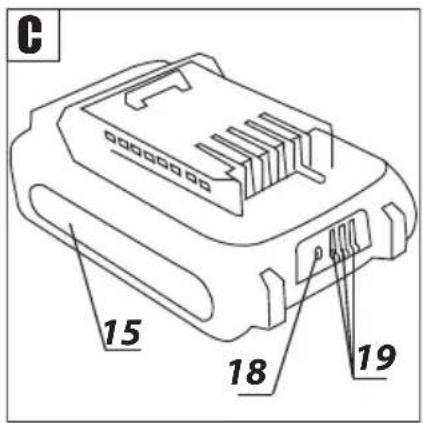
BATTERY LEVEL INDICATION

The battery is equipped with signalisation of the battery level (3 LED diodes) (19). To check battery level status, press the button for battery level indication (18) (fig. C). When all diodes are lit, the battery level is high. When 2 diodes are on, the battery is partially discharged. When only one diode is lit, the battery is discharged and must be recharged.
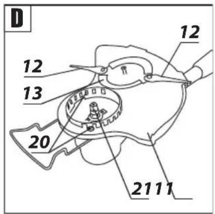
GUARD INSTALLATION

- Put the guard (11) on the motor casing, so the protective section is pointed towards the operator.
- Secure the guard (11) to the motor casing with the supplied screws (20) (fig. D).
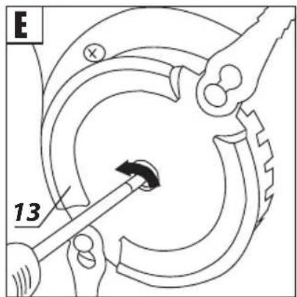
HEAD INSTALLATION

The head (13) is supplied disassembled with 2 attached cutting parts (12).
- Put the head (13) onto the spindle (21) so that its flat section with the hole matches the corresponding area of the spindle (fig. D).
- Use supplied screw and turn counter clockwise to tighten (left-hand thread) (fig. E).

The device can operate correctly only when the head is equipped with 2 cutting parts. Operation with only 1 cutting part is forbidden.
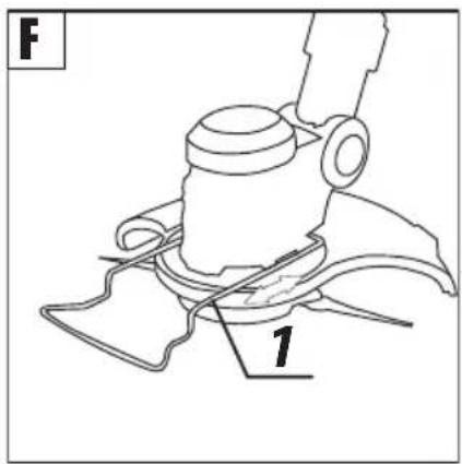
EDGE ROD

The edge rod is used to trim grass near edges and corners of lawns. It protects the cutting parts from damaging with sharp edges, e.g. concrete pavement sides.
- The edge rod (1) located on the motor casing can be adjusted by sliding it in or out, according to the needs (fig. F).
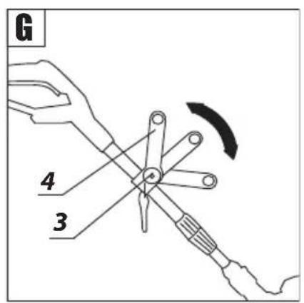
ADJUSTMENT OF THE AUXILIARY HANDLE

Auxiliary handle is designed for right- and left-handed persons. When starting operation always hold the grass trimmer firmly with both hands and by two handles.
- Loosen the locking knob for auxiliary handle (3) and set the auxiliary handle (4) in the optimal position for the task at hand (fig. G).
- Tighten the locking knob for auxiliary handle (3) to secure it in the position.
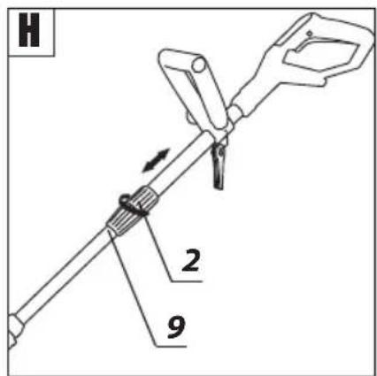
LENGTH ADJUSTMENT OF THE TELESCOPIC PIPE

Length adjustment of the telescopic pipe allows to match height of the tool with persons with various height and posture.
- Loosen the locking ring for telescopic pipe (2).
- Slide out/in the telescopic pipe (9) to desired length (fig. H).
- Lock by tightening the locking ring of the telescopic pipe (2).
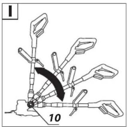
SETTING TILT ANGLE OF THE MAIN HANDLE

Thanks to convenient feature of adjustable head angular position related to the main handle, it is possible to trim lawn and flower bed edges and mow in hard to reach areas, e.g. under seats, hammock, table etc.
- Press in the locking button for head tilt angle (10).
- Press on the telescopic pipe (9) to choose desired angle of the head tilt (fig. 1).
- Release the locking button for head tilt angle (10) to automatically secure selected position.
GRAPHITE

Be very careful when using the grass trimmer for vertical trimming of lawns and flower bed edges. Stay away from the plane of cutting line rotation to avoid risk of being hit with an object projected by the cutting line.
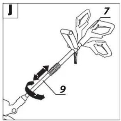
ROTATABLE MAIN HANDLE

Rotation of main handle in relation to the head by 90° clockwise or counter-clockwise allows to trim flower bed and lawn edges vertically.
- Hold the trimmer body and pull the telescopic pipe (9) and rotate it clockwise or counter-clockwise (follow the signs located on the ring).
- Release the pressure, and the spring action will make the telescopic pipe (9) with the main handle (7) lock in the selected position (fig. J).
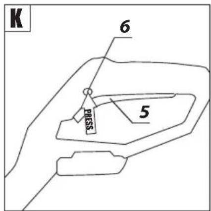
The grass trimmer switch features protection against accidental start up.
Switching on - press the switch lock button (6) and press the switch button (5) (fig. K).
Switching off – release pressure on the switch button (5).
Cutting parts rotate for some time after the motor is switched off. Never attempt to lock the switch in the ON position.
All parts must be assembled properly and must fulfil requirements that ensure appropriate and safe grass trimmer operation. Any damaged protective element or part must be repaired or replaced immediately.
GUIDELINES FOR SAFE AND EFFICIENT USE

- When trimming long grass perform the work gradually, by layers.
- Keep the grass trimmer away from hard objects and cultivated plants.
- Operate the grass trimmer only when the grass is dry.
- When trimming edges drive the tool along lawn edge.
Remove the battery from the device before commencing any activities related to installation, adjustment, repair or maintenance.
MAINTENANCE AND STORAGE

- Cleaning the device after each use is recommended.
- Clean ventilation holes in engine casing regularly.
- Remove grass residues from the guard and the head regularly.
- Never clean the device with water, aggressive fluids or solvents.
- Clean the device with brush or delicate cloth.
- Store the device in a dry place, beyond reach of children.
- Store the device with the battery removed.
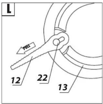
REPLACEMENT OF CUTTING PARTS

The grass trimmer is supplied with 20 spare cutting parts that are attached to the auxiliary handle. Use only recommended cutting parts.
- Put larger hole of the cutting part (12) over the pin (22) of the head (13) and pull outwards, so the pin (22) is in the smaller hole of the cutting part (12) (fig. L).
- Repeat the action for the second cutting part.
- Removal of the cutting part (12) is similar to installation, only the sequence of actions is reversed.
All defects should be repaired by service workshop authorized by the manufacturer.
TECHNICAL PARAMETERS
RATED PARAMETERS
| Cordless Grass Trimmer 58G030 | |
| Parameter Value | |
| Battery voltage 18 V DC | |
| Spindle rotational speed with no load | 9000 min -1 |
| Cutting width 254 mm | |
| Polymer blades 88,5 mm | |
| Number of blades attached to the head | 2 |
| Handle length adjustment 1,1 ÷ 1,4 m | |
| Protection class III | |
| Weight 1,8 kg | |
| Year of production 2021 | |
| 58G030 defines type and indication of the device | |
| Graphite Energy+ System Battery | ||
| Parameter Value | ||
| Battery 58G001 58G004 | ||
| Battery voltage 18 V DC 18 V DC | ||
| Battery type | Li-Ion | Li-Ion |
| Battery capacity | 2000 mAh | 4000 mAh |
| Ambient temperature range | 4^ - 40^ | 4^ - 40^ |
| Charging time for charger 58G002 | 1 h | 2 h |
| Weight 0,400 kg 0,650 kg | ||
| Year of production | 2021 | 2021 |
| Graphite Energy+ System Charger | |
| Parameter Value | |
| Charger type | 58G002 |
| Supply voltage | 230 V AC |
| Power supply frequency | 50 Hz |
| Charging voltage | 22 V DC |
| Max. charging current | 2300 mA |
| Ambient temperature range | 4°C - 40°C |
| Charging time of the battery 58G001 | 1 h |
| Charging time of the battery 58G004 | 2 h |
| Protection class | II |
| Weight | 0,300 kg |
| Year of production | 2021 |
NOISE LEVEL AND VIBRATION PARAMETERS
| Sound pressure | L_PA = 79,5 dB(A) K=3dB(A) |
| Sound power | L_WA = 91,9 dB(A) K=2,23dB(A) |
| Vibration acceleration (main handle) | a_h = 1,453 m/s^2K=1,5 m/s^2 |
| Vibration acceleration (auxiliary handle) | a_h = 3,224 m/s^2K=1,5 m/s^2 |
Noise and vibration information
Noise produced by the device is defined with: level of produced sound pressure L_PA and level of sound power L_WA (where K is measurement uncertainty). Vibrations produced by the device are defined with vibration acceleration value a_b (where K is measurement uncertainty).
Sound pressure L_FA sound power L_wA and vibration acceleration a_h , specified in this manual have been measured in accordance with the standard EN 60335-1:2012; EN 50636. Specified vibration level a_s can be used to compare tools and for initial evaluation of exposition to vibrations.
Specified vibration level is typical only for the main applications of the device. When the device is used for other purposes or with different working tools, the vibration level may change. Insufficient or too rare maintenance may increase vibration level. The abovementioned factors may lead to higher exposure to vibrations during whole working time. In order to precisely define exposure to vibrations, include periods when the device is switched off and when it is switched on but not used for working. Once all factors have been carefully considered, total exposition to vibrations may be significantly lower.
To protect the user from results of exposure to vibrations, use additional safety measures such as: device and working tool periodic maintenance, proper hand temperature conditions, good work organisation.
ENVIRONMENTAL PROTECTION
Electrical equipment must not be disposed off with household waste and, instead, should be utilized at appropriate facilities. Information on utilization can be provided by the product vendor or the local authorities. Waste electrical and electronic equipment contains substances that are not neutral to the natural environment. Equipment that is not recycled constitutes a potential hazard to the environment and to human health.
Storage batteries/batteries must not be disposed with domestic waste, put in a fire or into the water. Damaged or used up storage batteries must be properly recycled in compliance with the current directive pertaining to disposal of storage batteries and batteries.
Li-Ion
Right to introduce changes is reserved.
"Grupa Topex Spółka z ograniczoną odpowiedzialnością" Spółka komandytowa with seat in Warsaw at ul. Pograniczna 2/4 (hereinafter Grupa Topex) informs, that all copyrights to this instruction (hereinafter Instruction), including, but not limited to, text, photographs, schemes, drawings and layout of the instruction, belong to Grupa Topex exclusively and are protected by laws accordingly to Copyright and Related Rights Act of 4 February 2004 (ustawa o prawie autorskim i prawach pokrewnych, Dz. U. 2006 No 90 item 631 with later amendments). Copying, processing, publishing, modifications for commercial purposes of the entire Instruction or its parts without written permission of Grupa Topex are strictly forbidden and may cause civil and legal liability.
natural_image
Four black-and-white icons representing warning, person reading, open book, and person wearing headphones (no text or symbols)1234
5
1011
natural_image
Four black-and-white icons representing different environmental or safety symbols: a wheel, directional arrows, a square, and a house with raindrops (no text or labels)1314

1920
GRAFISKÄS DALAS APRAKSTS
natural_image
Four black-and-white icons representing warning, person reading, open book, and person wearing headphones (no text or symbols)1234

5
1011
natural_image
Four black-and-white icons representing different environmental or safety symbols: bicycle, hand gesture, square, and house (no text or labels)15
1314
1718
1920

m = 311

The Ground Truth image displays a single, solid horizontal line. According to Rule 2 (UNDERSCORE & LINE RULES), if the GT contains lines used for stylistic emphasis or as background elements (like ruled paper), the OCR result must ignore them. The provided OCR content is "____", which consists of four underscores. This is incorrect because underscores are not equivalent to a solid line and are not permitted under the “Stylistic/Background Lines (Ignore)” rule. The OCR has hallucinated underscores where none should exist in the GT, violating the “Stylistic/Background Lines (Ignore)” rule. Therefore, the OCR result is inconsistent with the Ground Truth.
5
6

7
8
9
1011
m = 311

12

1314

1718

15
16

1718


1920

POSEBNI PROPISI O SIGURNOSTI
DODATNI POSEBNI ZAHTJEVI ZA RAD TRIMERA ZA TRAVU NAPA-JANJG IZ AKU-BATERIJE
natural_image
Four black-and-white icons representing warning, person reading, open book, and person wearing headphones (no text or symbols)1234
6
1011
natural_image
Four black-and-white icons representing different behaviors: wheel, directional arrows, square, and house (no text or symbols)15
1920
OPBOUW EN BESTEMMING
MONTAGE VAN DE AFSCHERMING

DRAAIEND HOOFDHANDVAT
