
58G716 - Drill Graphite - Free user manual and instructions
Find the device manual for free 58G716 Graphite in PDF.


| Product Type | Rotary Drill |
| Brand | Graphite |
| Model | 58G716 |
| Power Supply | Corded Electric (230V) |
| Power Consumption | 650 W |
| No-Load Speed | 0-2800 rpm (variable) |
| Chuck Type | Keyless, 13 mm |
| Max Drilling Diameter (Steel) | 13 mm |
| Max Drilling Diameter (Wood) | 30 mm |
| Max Drilling Diameter (Concrete) | 16 mm |
| Impact Function | Yes, for hammer drilling |
| Speed Control | Variable speed trigger |
| Forward/Reverse | Yes |
| Weight | 1.8 kg |
| Dimensions (L x W x H) | 270 x 210 x 70 mm |
| Cable Length | 2.5 m |
| Safety Features | Double insulation, safety switch |
| Accessories Included | Drill bit set, auxiliary handle, depth stop |
| Maintenance | Clean vents, lubricate gears periodically |
| Repairability | Spare parts available via service centers |
Frequently Asked Questions - 58G716 Graphite
User questions about 58G716 Graphite
0 question about this device. Answer the ones you know or ask your own.
Ask a new question about this device
Download the instructions for your Drill in PDF format for free! Find your manual 58G716 - Graphite and take your electronic device back in hand. On this page are published all the documents necessary for the use of your device. 58G716 by Graphite.
USER MANUAL 58G716 Graphite

natural_image
Three sequential illustrations of a mechanical device with gear and shaft, showing progressive tool movement (no text or symbols)INSTRUKCJA ORYGINALNA (OBSŁUGI)

WIERTARKA UDAROWA
58G716
UWAGA: PRZED PRZYSTĄPIENIEM DO UŻYTKOWANIA ELEKTRONARZĘDZIA NALEŻY UWAŻNIE PRZECZYTAĆ NINIEJSZĄ INSTRUKCJĘ I ZACHOWAĆ JĄ DO DALSZEGO WYKORZYSTANIA.
SZCZEGÓŁOWE PRZEPISY BEZPIECZEŃSTWA
/Declaration of Conformity/
/The above listed product is in conformity with the following UE Directives:/
/Machinery Directive 2006/42/EC/
/ 2006/42/EK Gépek /
/EMC Directive 2004/108/EC/
/and fulfi ls requirements of the following Standards:/
/Last two figures of CE marking year:/
/Name and address of the person who established in the Community and authorized to compile the technical file/
/GRUPA TOPEX Quality Agent /
CAUTION: BEFORE USING THE POWER TOOL READ THIS MANUAL CAREFULLY AND KEEP IT FOR FUTURE REFERENCE.
DETAILED SAFETY REGULATIONS
- Use ear protectors when operating impact drill. Noise hazards may cause hearing loss.
- Use additional handles supplied with the tool. Loss of control may cause operator personal injury.
Description of improper use ●
Do not throw the tool, do not overload, do not immerse in water or other fluids, do not use for mixing adhesive or cement mortars, do not hang, carry, pull or unplug the power tool by pulling the cord. Avoid using long extension cords.
Accessories that you can use •
Wood, metal and masonry drills, grinding discs and wire brushes (wear safety goggles when using grinding discs and wire brushes).
CAUTION! This device is designed to operate indoors.
The design is assumed to be safe, protection measures and additional safety systems are used, nevertheless there is always a small risk of operational injuries.
CONSTRUCTION AND USE
Impact drills are hand operated power tools with insulation class II. Tools are driven by single-phase commutator motors with rotational speed reduced with gear transmission. This type of power tools is widely used for making holes in wood, wood-like materials, metals, ceramics and plastics (rotation only), and concrete, bricks and alike (with impact). Range of use covers repair and building works, woodworking and any work from the scope of individual, amateur activities (tinkering).

Use the power tool according to the manufacturer's instructions only.
DESCRIPTION OF DRAWING PAGES
Below enumeration refers to the device elements depicted on the drawing pages of this manual.
Drill chuck1.
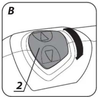
Operation mode switch2.
Switch lock button 3.
- Direction selector switch
- Speed control wheel
- Switch
- Additional handle
- Depth gauge rod
* Slight differences may appear between the product and drawing
MEANING OF SYMBOLS


CAUTION
WARNING
ASSEMBLY/SETTINGS
INFORMATION
EQUIPMENT AND ACCESSORIES
Key - handwheel - 1 pce1.
Additional handle - 1 pce2.
Depth gauge rod - 1 pce3.
Drills - 1 pce4.
Transport case - 1 pce5.
INSTALLATION OF ADDITIONAL HANDLE

Due to personal safety issues it is recommended to always use the additional handle (7). Possibility to rotate the additional handle before it is clamped on the drill body allows choosing the position most comfortable for specific working conditions.

Disconnect the power tool from power supply.
- Loosen the wheel lock that locks collar of the locking handle (7) by turning it counter-clockwise.
Slide the handle collar over cylindrical part of the drill body. ●
Turn for the most comfortable position. ●
Turn the wheel lock clockwise tightly to clamp the handle. ●
DEPTH GAUGE INSTALLATION

Depth gauge (8) serves to limit the depth of drill penetration of material.
- Loosen the wheel lock, which blocks collar of the additional handle (7).
- Slide depth gauge rod (8) into the hole in the additional handle collar.
Set desired drill depth.
Fix by tightening the wheel lock.
INSTALLATION OF WORKING TOOLS

Disconnect the power tool from power supply.
- Insert key into one of the holes on the side wall of the drill chuck (1).
Open jaws to desired dimension. - Insert cylindrical drill shank into the chuck, push it to the limit.
- Tighten jaws on drill shank with the key (insert it into three holes on the chuck side wall).

Remember to always remove the key from the chuck after you finish drill installation or removal.

When a new drill is installed, observe against excessive drill wobble after start-up. This may indicate improper fixing in the chuck or deviated drill. If you observe wobbling, check fixing of the drill and its technical condition. Check drill chuck on a regular basis, before each use of the drill.
SWITCHING ON / SWITCHING OFF

The mains voltage must match the voltage on the rating plate of the drill.
Switching on - press the switch button (6) and hold in this position.
Switching off – release pressure on the switch (6).
Locking the switch (continuous operation)
Switching on:
- Press the switch button (6) and hold in this position.
- Press the switch lock button (3) (fig. A).
- Release pressure on the switch (6).
Switching off:
- Press and release the switch (6).

Range of rotational speed of the spindle is controlled with pressure on the switch button.
WHEEL FOR SPINDLE ROTATIONAL SPEED CONTROL

Drill allows for operation with different spindle speeds. It can be controlled with the wheel (5) (fig. A). For each setting of the wheel for speed control, the speed can be adjusted continuously by increasing or decreasing pressure on the switch button (6).
- Increase the speed by turning the wheel (5) clockwise.
- Reduce the speed by turning the wheel (5) counter-clockwise.

Choose appropriate rotational speed when the drill operates with no load, with pressed switch lock button. Speed that is set in this way may decrease under load.

Never change the switch position under operation of the drill. It may damage the power tool.
LEFT - RIGHT DIRECTION OF ROTATION

Choose direction of spindle rotation with the selector switch (4) (fig. A).
Right rotation - move the switch (4) to the extreme left position.
Left rotation - move the switch (4) to the extreme right position.
* The possibility is reserved that in certain cases position of the switch relating to rotation direction may be different than specified. Please refer to graphic signs placed on the switch or tool body.

Do not change direction of rotation when the spindle of the drill is rotating. Check if the position of the selector switch is correct before starting the tool.
Operation mode switch (2) allows for choosing suitable work mode: drilling with or without impact (fig. B). Set the operation mode switch in the position for drilling without impact (drill symbol), when processing materials like metal, wood, ceramics, plastics and alike. Set the operation mode switch in the position for drilling with impact (hammer symbol), when processing materials like stone, concrete, brick and alike. Holes in wood, wood-like materials and metals are made with drills of high speed steel or carbon steel (the latter for wood and wood-like materials only). For stroke drilling special drills with sintered carbide inserts should be used.

Do not use left direction of rotation when stroke function is on.
DRILLING HOLES

- When drilling a hole with large diameter, it is recommended to drill smaller hole and then ream it to appropriate diameter. It prevents overloading the drill.
- When drilling deep holes drill gradually to smaller depths, then remove drill to remove chips and dust from the hole.
- If a drill jam occurs during drilling, turn off the drill immediately to prevent its damage. Change direction of rotation to remove the drill from the hole.
- Keep the drill in the axis of the hole. Keeping the drill perpendicular to the surface of the processed material is highly desirable. Doing otherwise may cause drill jam or breaking in the hole and a user injury in consequence.

Long lasting drilling at low rotational speed of the spindle may cause motor overheating. Provide periodic breaks during operation or let the tool operate at maximum speed with no load for approximately 3 minutes. Do not cover holes for motor ventilation in the tool body.
Unplug the power cord from the mains socket before commencing any activities related to installation, adjustment, repair or maintenance.
Impact drill does not require any additional lubrication or special maintenance. There are no user serviceable parts inside the tool. Never use water or other chemical liquids for cleaning the drill. Wipe the tool with a dry cloth only. Always keep the drill in dry place. Always keep the ventilation holes on the drill body pervious. In case of power cord damage replace it with a cord with the same specification. Entrust the repair to a qualified specialist or a service.
DRILL CHUCK REPLACEMENT

- Open chuck (1) jaws.
- Unscrew the chuck fixing screw with cross screwdriver, by turning it clockwise (left-hand thread).
• Install hex key in the chuck (fig. D).
Gently tap free end of the hex key. ●
Unscrew the chuck. ●

Installation of the chuck is similar to deinstallation, only the sequence of actions is reversed. Drill chuck must be firmly screwed with approx. 30 - 35 Nm torque. Check drill chuck regularly against damages.
REPLACEMENT OF CARBON BRUSHES

Replace immediately used up (shorter than 5 mm), burnt or cracked motor carbon brushes. Always replace both brushes at a time.
Entrust replacement of carbon brushes only to a qualified person. Only original parts should be used.

All faults should be repaired by service workshop authorized by the manufacturer.
TECHNICAL PARAMETERS
RATED PARAMETERS
| Drill | ||
| Parameter Value | ||
| Supply voltage 230 V AC | ||
| Current frequency 50 Hz | ||
| Power consumption 650 W | ||
| No load rotational speed 0-3000 rpm | ||
| Clamping range 1,5-13 mm | ||
| Spindle thread | 1/2”x 20 mm | |
| Maximum drilling diameter | steel | 10 mm |
| wood | 25 mm | |
| concrete | 13 mm | |
| Strokes per minute | 0-48000 spm | |
| Protection class | II | |
| Weight | 2 kg | |
| Year of production 2014 | ||
NOISE LEVEL AND VIBRATION PARAMETERS
Sound pressure: Lp_A=96,3 dB(A) K=3 dB(A)
Sound power: Lw_A=107,3 dB(A) K=3 dB(A)
Vibration acceleration: a_h=15,31 m/s^2 K=1,5 m/s^2
ENVIRONMENT PROTECTION
Do not dispose of electrically powered products with household wastes, they should be utilized in proper plants. Obtain information on wastes utilization from your seller or local authorities. Used up electric and electronic equipment contains substances active in natural environment. Unrecycled equipment constitutes a potential risk for environment and human health.
* Right to introduce changes is reserved.
"Grupa Topex Spółka z ograniczoną odpowiedzialnością" Spółka komandytowa with seat in Warsaw at ul. Pograniczna 2/4 (hereinafter Grupa Topex) informs, that all copyrights to this instruction (hereinafter Instruction), including, but not limited to, text, photographies, schemes, drawings and layout of the instruction, belong to Grupa Topex exclusively and are protected by laws accordingly to Copyright and Related Rights Act of 4 February 2004 (ustawa o prawie autorskim i prawach pokrewnych, Dz. U. 2006 No 90 item 631 with later amendments). Copying, processing, publishing, modifications for commercial purposes of the entire Instruction or its parts without written permission of Grupa Topex are strictly forbidden and may cause civil and legal liability.
SCHLAGBOHRMASCHINE
58G716
Schlüssel - Knopf - 1 St.1.
Transport Koffer - 1 St.5.
DARBA REŽIMA PĀRSLĒDZĒJS

POSEBNI PROPISI O SIGURNOSTI
- Koristite štitnike sluha za vrijeme rada s udarnom bušilicom. Ako se izlažete buci, to može dovesti do gubitka sluha.
- Alat koristite s dodatnim drškama koje su s njim dostavljene. Gubitak kontrole može dovesti do osobnih povreda radnika.


- INSTRUKCJA ORYGINALNA (OBSŁUGI)
- WIERTARKA UDAROWA
- 58G716
- SZCZEGÓŁOWE PRZEPISY BEZPIECZEŃSTWA
- DETAILED SAFETY REGULATIONS
- Description of improper use ●
- Accessories that you can use •
- CONSTRUCTION AND USE
- DESCRIPTION OF DRAWING PAGES
- MEANING OF SYMBOLS
- EQUIPMENT AND ACCESSORIES
- INSTALLATION OF ADDITIONAL HANDLE
- DEPTH GAUGE INSTALLATION
- INSTALLATION OF WORKING TOOLS
- SWITCHING ON / SWITCHING OFF
- Locking the switch (continuous operation)
- Switching on:
- Switching off:
- WHEEL FOR SPINDLE ROTATIONAL SPEED CONTROL
- LEFT - RIGHT DIRECTION OF ROTATION
- DRILLING HOLES
- DRILL CHUCK REPLACEMENT
- REPLACEMENT OF CARBON BRUSHES
- TECHNICAL PARAMETERS
- NOISE LEVEL AND VIBRATION PARAMETERS
- ENVIRONMENT PROTECTION
- SCHLAGBOHRMASCHINE
- DARBA REŽIMA PĀRSLĒDZĒJS
- POSEBNI PROPISI O SIGURNOSTI
Brand : Graphite
Model : 58G716
Category : Drill