KC300.9 - Saw KRESS - Free user manual and instructions
Find the device manual for free KC300.9 KRESS in PDF.

User questions about KC300.9 KRESS
0 question about this device. Answer the ones you know or ask your own.
Ask a new question about this device
Download the instructions for your Saw in PDF format for free! Find your manual KC300.9 - KRESS and take your electronic device back in hand. On this page are published all the documents necessary for the use of your device. KC300.9 by KRESS.
USER MANUAL KC300.9 KRESS
natural_image
Black Kress chain saw with visible teeth and branding (no text or symbols on the instrument itself)| Cordless Chainsaw | EN | P03 |
| Akku-Kettensäge | D | P25 |
| Tronçonneuse sans fil | F | P49 |
| Motosega a batteria | I | P72 |
| Motosierra inalámbrica | ES | P95 |
| Motosserra sem fios | PT | P118 |
| Draadloze kettingzaag | NL | P141 |
| Akkus láncfúrész | HU | P164 |
| Ferăstrău cu lanț cu accumulator | RO | P187 |
| Bezprzewodowa piła łańcuchowa | PL | P210 |
| Akumulátorová řetězová pila | CZ | P233 |
| Akumulátorová reťazová píla | SK | P256 |
| Brezžična verižna žaga | SL | P279 |
| Akumulatorska lančana pila | HR | P301 |
| Batteridreven motorsav | DK | P323 |
| Akkukäyttöinen moottorisaha | FIN | P344 |
| Trådløs motorsag | NOR | P365 |
| Batteridriven kedjesåg | SV | P386 |
KC300 KC300.X
TABLE OF CONTENTS
INTRODUCTION....3
COMPONENT LIST....5
PRODUCT SAFETY....6
ASSEMBLY & OPERATION....12
TRANSPORTATION ....17
SAW MAINTENANCE 18
CLEANNING....20
STORAGE....20
TROUBLESHOOTING 21
TECHNICAL DATA 22
DECLARATION OF CONFORMITY 23
INTRODUCTION
Dear Customer,
Thank you for buying this Kress Commercial product. We are dedicated to developing high quality products to meet your commercial landscaping requirements.
The Kress brand is synonymous with premium quality service. Over the years of your product's life, if you have any questions or concerns about your product, please contact your dealer or our Customer Service Team for assistance.
We are confident you will enjoy working with your Kress product for years to come.
INTENDED USE
This Chainsaw is designed for felling trees, limbing, bucking tree trunks, cutting wooden beams, etc. All cuts should be across the grain. This product is intended for cutting wood only.
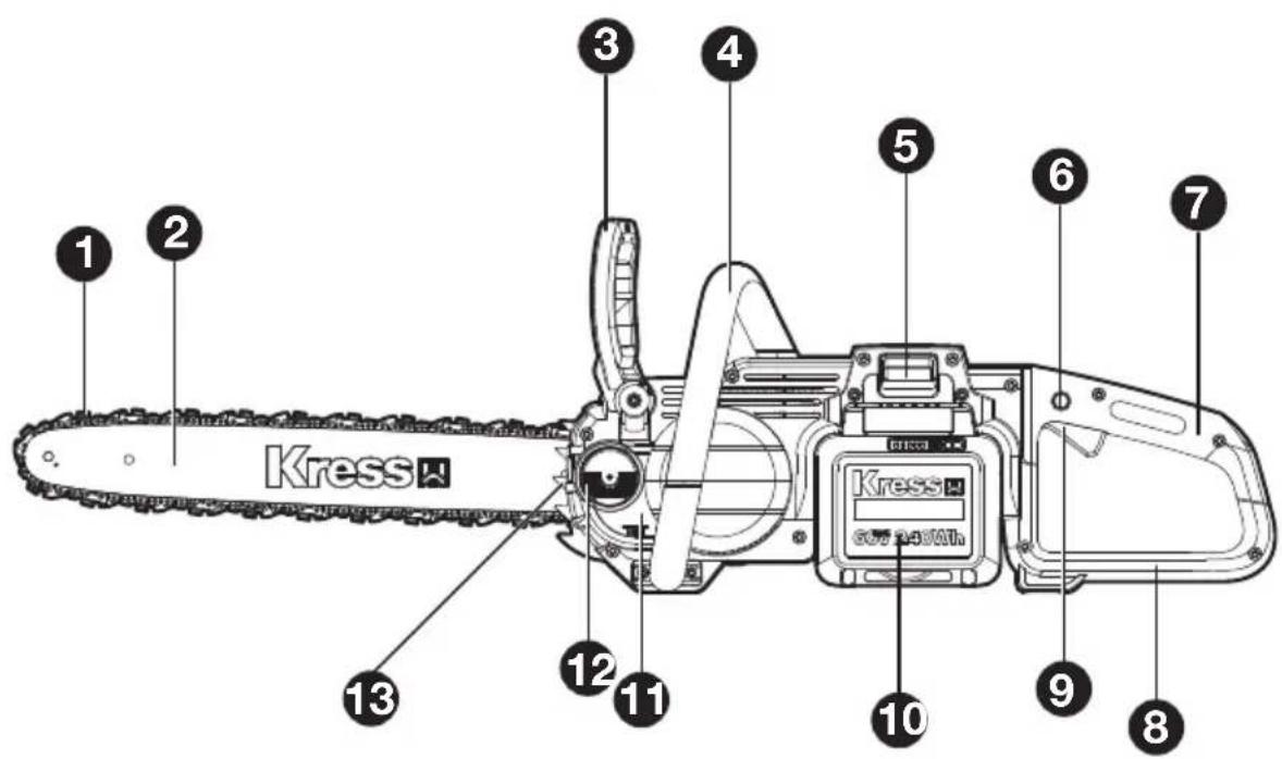


COMPONENT LIST
- CHAIN
- GUIDE BAR
- CHAIN BRAKE LEVER (HAND GUARD)
- FRONT HANDLE
- BATTERY PACK RELEASE BUTTON
- LOCK-OFF BUTTON
- REAR HANDLE
- REAR HAND GUARD
- ON/OFF SWITCH
- BATTERY PACK *
- OIL LEVEL WINDOW
- OIL FILLER CAP
- BUMPER SPIKE
- DRIVE COVER
- HEX NUTS
- CHAIN TENSIONING SCREW
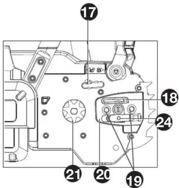
- CHAIN DIRECTION SYMBOL
- OIL OUTLET
- BAR LOCATING STUDS
- BAR PAD
- DRIVE SPROCKET
- PROTECTIVE SCABBARD
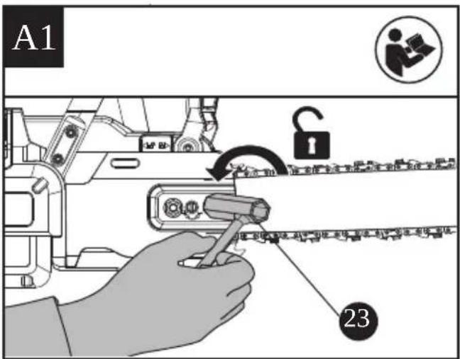
- WRENCH (SEE FIG A1)
- CHAIN TENSIONING PIN
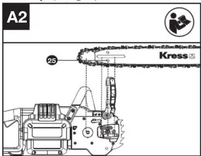
- CHAIN TENSIONING HOLE (SEE FIG A2)
ORIGINAL INSTRUCTIONS PRODUCT SAFETY GENERAL POWER TOOL SAFETY WARNINGS
WARNING Read all safety warnings, instructions, illustrations and specifications provided with this power tool. Failure to follow all instructions listed below may result in electric shock, fire and/or serious injury.
Save all warnings and instructions for future reference.
The term “power tool” in the warnings refers to your mains-operated (corded) power tool or battery-operated (cordless) power tool.
1. WORK AREA SAFETY
a) Keep work area clean and well lit. Cluttered or dark areas invite accidents.
b) Do not operate power tools in explosive atmospheres, such as in the presence of flammable liquids, gases or dust. Power tools create sparks which may ignite the dust or fumes.
c) Keep children and bystanders away while operating a power tool. Distractions can cause you to lose control.
2. ELECTRICAL SAFETY
a) Power tool plugs must match the outlet. Never modify the plug in any way. Do not use any adapter plugs with earthed (grounded) power tools. Unmodified plugs and matching outlets will reduce risk of electric shock.
b) Avoid body contact with earthed or grounded surfaces, such as pipes, radiators, ranges and refrigerators. There is an increased risk of electric shock if your body is earthed or grounded.
c) Do not operate the machine in rain or wet conditions. This may increase the risk of electric shock. Once got wet in the rain during operation, the machine and the battery should be dried before storing or charging. Remove the battery and reinsert it if the machine fails to turn on. Keep battery connection free of dirt and debris, and clean with a soft and dry brush or cloth.
d) Do not abuse the cord. Never use the cord for carrying, pulling or unplugging the power tool. Keep cord away from heat, oil, sharp edges or moving parts. Damaged or entangled cords increase the risk of electric shock.
e) When operating a power tool outdoors, use an extension cord suitable for outdoor use. Use of a cord suitable for outdoor use reduces the risk of electric shock.
f) If operating a power tool in a damp location is unavoidable, use a residual current device (RCD) protected supply. Use of an RCD reduces the risk of electric shock.
3. PERSONAL SAFETY
a) Stay alert, watch what you are doing and use common sense when operating a power tool. Do not use a power tool while you are tired or under the influence of drugs, alcohol or medication. A moment of inattention while operating power tools may result in serious personal injury.
b) Use personal protective equipment. Always wear eye protection. Protective equipment such as dust mask, non-skid safety shoes, hard hat, or hearing protection used for appropriate conditions will reduce personal injuries.
c) Prevent unintentional starting. Ensure the switch is in the off-position before connecting to power source and/or battery pack, picking up or carrying the tool. Carrying power tools with your finger on the switch or energising power tools that have the switch on invites accidents.
d) Remove any adjusting key or wrench before turning the power tool on. A wrench or a key left attached to a rotating part of the power tool may result in personal injury.
e) Do not overreach. Keep proper footing and balance at all times. This enables better control of the power tool in unexpected situations.
f) Dress properly. Do not wear loose clothing or jewellery. Keep your hair, clothing and gloves away from moving parts. Loose clothes, jewellery or long hair can be caught in moving parts.
g) If devices are provided for the connection of dust extraction and collection facilities, ensure these are connected and properly used. Use of dust collection can reduce dust-related hazards.
h) Do not let familiarity gained from frequent use of tools allow you to become complacent and ignore tool safety principles. A careless action can cause severe injury within a fraction of a second.
4. POWER TOOL USE AND CARE
a) Do not force the power tool. Use the correct power tool for your application. The correct power tool will do the job better and safer at the rate for which it was designed.
b) Do not use the power tool if the switch does not turn it on and off. Any power tool that cannot be controlled with the switch is dangerous and must be repaired.
c) Disconnect the plug from the power source and/or the battery pack from the power tool before making any adjustments, changing accessories, or storing power tools. Such preventive safety measures reduce the risk of starting the power tool accidentally.
d) Store idle power tools out of the reach of children and do not allow persons unfamiliar with the power tool or these instructions to operate the power tool. Power tools are dangerous in the hands of untrained users.
e) Maintain power tools. Check for misalignment or binding of moving parts, breakage of parts and any other condition that may affect the
power tool's operation. If damaged, have the power tool repaired before use. Many accidents are caused by poorly maintained power tools.
f) Keep cutting tools sharp and clean. Properly maintained cutting tools with sharp cutting edges are less likely to bind and are easier to control.
g) Use the power tool, accessories and tool bits etc. in accordance with these instructions, taking into account the working conditions and the work to be performed. Use of the power tool for operations different from those intended could result in a hazardous situation.
h) Keep handles and grasping surfaces dry, clean and free from oil and grease. Slippery handles and grasping surfaces do not allow for safe handling and control of the tool in unexpected situations.
5. BATTERY TOOL USE AND CARE
a) Recharge only with the charger specified by the manufacturer. A charger that is suitable for one type of battery pack may create a risk of fire when used with another battery pack.
b) Use power tools only with specifically designated battery packs. Use of any other battery packs may create a risk of injury and fire.
c) When battery pack is not in use, keep it away from other metal objects, like paper clips, coins, keys, nails, screws or other small metal objects, that can make a connection from one terminal to another. Shorting the battery terminals together may cause burns or a fire.
d) Under abusive conditions, liquid may be ejected from the battery; avoid contact. If contact accidentally occurs, flush with water. If liquid contacts eyes, additionally seek medical help. Liquid ejected from the battery may cause irritation or burns.
e) Do not use a battery pack or tool that is damaged or modified. Damaged or modified batteries may exhibit unpredictable behaviour resulting in fire, explosion or risk of injury.
f) Do not expose a battery pack or tool to fire or excessive temperature. Exposure to fire or temperature above 130 °C may cause explosion.
g) Follow all charging instructions and do not charge the battery pack or tool outside the temperature range specified in the instructions. Charging improperly or at temperatures outside the specified range may damage the battery and increase the risk of fire.
6. SERVICE
a) Have your power tool serviced by a qualified repair person using only identical replacement parts. This will ensure that the safety of the power tool is maintained.
b) Never service damaged battery packs. Service of battery packs should only be performed by the manufacturer or authorized service providers.
1) GENERAL CHAIN SAW SAFETY WARNINGS:
a) Keep all parts of the body away from the saw chain when the chain saw is operating. Before you start the chain saw, make sure the saw chain is not contacting anything. A moment of inattention while operating chain saws may cause entanglement of your clothing or body with the saw chain.
b) Always hold the chain saw with your right hand on the rear handle and your left hand on the front handle. Holding the chain saw with a reversed hand configuration increases the risk of personal injury and should never be done.
c) Hold the chain saw by insulated gripping surfaces only, because the saw chain may contact hidden wiring. Saw chains contacting a "live" wire may make exposed metal parts of the chain saw "live" and could give the operator an electric shock.
d) Wear safety glasses protection. Further protective equipment for hearing, head, hands, legs and feet is recommended.
Adequate protective clothing will reduce personal injury by flying debris or accidental contact with the saw chain.
e) Do not operate a chain saw, on a ladder, from a rooftop, or any unstable support. Operation of a chain saw in this manner could result in serious personal injury.
f) Always keep proper footing and operate the chain saw only when standing on fixed, secure and level surface. Slippery or unstable surfaces may cause a loss of balance or control of the chain saw.
g) When cutting a limb that is under tension, be alert for spring back. When the tension in the wood fibres is released, the spring loaded limb may strike the operator and/or throw the chain saw out of control.
h) Use extreme caution when cutting brush and saplings. The slender material may catch the saw chain and be whipped toward you or pull you off balance.
i) Carry the chain saw by the front handle with the chain saw switched off and away from your body. When transporting or storing the chain saw, always fit the guide bar cover. Proper handling of the chain saw will reduce the likelihood of accidental contact with the moving saw chain.
j) Follow instructions for lubricating, chain tensioning and changing the bar and chain. Improperly tensioned or lubricated chain may either break or increase the chance for kickback.
k) Cut wood only. Do not use chain saw for purposes not intended. For example: do not use chain saw for cutting metal, plastic, masonry or non-wood building materials. Use of the chain saw for operations different than intended could result in a hazardous situation.
I) Do not attempt to fell a tree until you have an
understanding of the risks and how to avoid them. Serious injury could occur to the operator or bystanders while felling a tree.
m) Follow all instructions when clearing jammed material, storing or servicing the chain saw. Make sure the switch is off and the battery pack is removed. Unexpected actuation of the chain saw while clearing jammed material or servicing may result in serious personal injury.
n) Recommendation that the first-time user should, as a minimum, practice cutting logs on a saw-horse or cradle.
o) Recommendation to have sharpening and maintenance of the saw chain performed by authorised service centers.
2) CAUSES AND OPERATOR PREVENTION OF KICKBACK:
Kickback may occur when the nose or tip of the guide bar touches an object, or when the wood closes in and pinches the saw chain in the cut. Tip contact in some cases may cause a sudden reverse reaction, kicking the guide bar up and back towards the operator. Pinching the saw chain along the top of the guide bar may push the guide bar rapidly back towards the operator.
Either of these reactions may cause you to lose control of the saw which could result in serious personal injury. Do not rely exclusively upon the safety devices built into your saw. As a chain saw user, you should take several steps to keep your cutting jobs free from accident or injury.
Kickback is the result of chain saw misuse and/or incorrect operating procedures or conditions and can be avoided by taking proper precautions as given below:
a) Maintain a firm grip, with thumbs and fingers encircling the chain saw handles, with both hands on the saw and position your body and arm to allow you to resist kickback forces. Kickback forces can be controlled by the operator, if proper precautions are taken. Do not let go of the chain saw.
b) Do not overreach and do not cut above shoulder height. This helps prevent unintended tip contact and enables better control of the chain saw in unexpected situations.
c) Only use replacement bars and chains specified by the manufacturer. Incorrect replacement guide bars and saw chains may cause chain breakage and/or kickback.
d) Follow the manufacturer's sharpening and maintenance instructions for the saw chain. Decreasing the depth gauge height can lead to increased kickback.
RESIDUAL RISKS
Even with the intended use of the appliance there is always a residual risk, which can not prevented. According to the type and construction of the appliance the following potential hazards might apply:
- Contact with exposed saw teeth of the saw chain (cutting hazards)
- Access to the rotating saw chain (cutting hazards)
- Unforeseen, abrupt movement of the guide bar (cutting hazards)
- Flung out of parts from the saw chain (Cutting / injection hazards)
- Flung out of parts of the work piece
- Skin contact with the oil
- Loss of hearing, if no required ear protection used during work
SAFETY WARNINGS FOR BATTERY PACK
a) Do not dismantle, open or shred cells or battery pack.
b) Do not short-circuit a battery pack. Do not store battery packs haphazardly in a box or drawer where they may short-circuit each other or be short-circuited by conductive materials. When battery pack is not in use, keep it away from other metal objects, like paper clips, coins, keys, nails, screws or other small metal objects, that can make a connection from one terminal to another. Shorting the battery terminals together may cause burns or a fire.
c) Do not expose battery pack to heat or fire. Avoid storage in direct sunlight.
d) Do not subject battery pack to mechanical shock.
e) In the event of battery leaking, do not allow the liquid to come into contact with the skin or eyes. If contact has been made, wash the affected area with copious amounts of water and seek medical advice.
f) Keep battery pack clean and dry.
g) Wipe the battery pack terminals with a clean dry cloth if they become dirty.
h) Battery pack needs to be charged before use. Always refer to this instruction and use the correct charging procedure.
i) Do not maintain battery pack on charge when not in use.
j) After extended periods of storage, it may be necessary to charge and discharge the battery pack several times to obtain maximum performance.
k) Recharge only with the charger specified by Kress. Do not use any charger other than that specifically provided for use with the equipment.
I) Do not use any battery pack which is not designed for use with the equipment.
m) Keep battery pack out of the reach of children.
n) Retain the original product literature for future reference.
o) Remove the battery from the equipment when not in use.
p) Dispose of properly.
q) Do not use battery packs of different manufacture, size or type.
r) Keep the battery away from microwaves and high pressure.
User manual requirements for wireless product
a) Operation of this device is subject to the following two conditions:
(1) This device may not cause harmful interference, and
(2) this device must accept any interference received, including interference that may cause undesired operation.
b) Caution: Changes or modifications to this unit not expressly approved by the party responsible for compliance could void the user's authority to operate the equipment.
c) NOTE: This equipment generates, uses and can radiate radio frequency energy and, if not installed and used in accordance with the instructions, may cause harmful interference to radio communications. However, there is no guarantee that interference will not occur in a particular installation. If this equipment does cause harmful interference to radio or television reception, which can be determined by turning the equipment off and on, the user is encouraged to try to correct the interference by one or more of the following measures:
-Reorient or relocate the receiving antenna.
-Increase the separation between the equipment and receiver.
-Connect the equipment into an outlet on a circuit different from that to which the receiver is connected.
-Consult the dealer or an experienced radio/TV technician for help
SAVE THESE INSTRUCTIONS
Instructions concerning the proper techniques for basic felling, limbing, and cross-cutting (bucking)
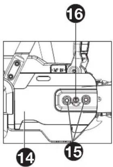
1. Felling a tree
When bucking and felling operations are being performed by two or more persons at the same time, the felling operations should be separated from the bucking operation by a distance of at least twice the height of the tree being felled. Trees should not be felled in a manner that would endanger any person, strike any utility line or cause any property damage. If the tree does make contact with any utility line, the company should be notified immediately.
The Chainsaw operator should keep on the uphill side of the terrain as the tree is likely to roll or slide downhill after it is felled.
An escape path should be planned and cleared as necessary before cuts are started. The escape path should extend back and diagonally to the rear of the expected line of fall as illustrated in Figure 1. Before felling is started, consider the natural lean of the tree, the location of larger branches and the wind direction to judge which way the tree will fall. Remove dirt, stones, loose bark, nails, staples and wire from the tree.
2. Notching undercut
Make the notch 1/3 the diameter of the tree, perpendicular to the direction of falls as illustrated in Figure 1. Make the lower horizontal notching cut (W) first. This will help to avoid pinching either the saw chain or the guide bar when the second notch (X) is being made.
3. Felling back cut
Make the felling back cut (Y) at least 50 mm higher than the horizontal notching cut as illustrated in Figure 1.
Keep the felling back cut parallel to the horizontal notching cut.
Make the felling back cut so enough wood is left to act as a hinge. The hinge wood keeps the tree from twisting and falling in the wrong direction. Do not cut through the hinge.
As the felling gets close to the hinge, the tree should begin to fall. If there is any chance that the tree may not fall in desired direction or it may rock back and bind the saw chain, stop cutting before the felling back cut is complete and use wedges of wood, plastic or aluminium (Z) to open the cut and drop the tree along the desired line of fall
When the tree begins to fall remove the Chainsaw from the cut, stop the motor, put the Chainsaw down, then use the retreat path planned ② Be alert for overhead limbs falling and watch your footing. (See Figure 1)
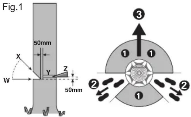
4. Limbing a tree
Limbing is removing the branches from a fallen tree.
When limbing leave larger lower limbs to support the log off the ground. Remove the small limbs in one cut as illustrated in Figure 2. Branches under tension should be cut from the bottom up to avoid binding the Chainsaw.
natural_image
Diagram of a mechanical or structural component with directional arrows indicating movement, labeled Fig.2 (no text or symbols on the diagram itself)5. Bucking a log
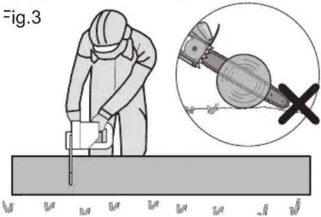
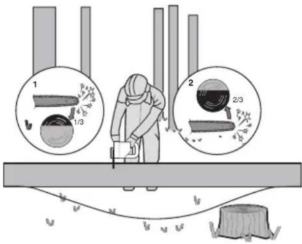
Bucking is cutting a log into lengths. It is important to make sure your footing is firm and your weight is evenly distributed on both feet. When possible, the log should be raised and supported by the use of limbs, logs or chocks. Follow the simple directions for easy cutting.
When the log is supported along its entire length as illustrated in Figure 3, it is cut from the top (overbuck), avoid contacting ground as this will greatly reduce the chain sharpness.
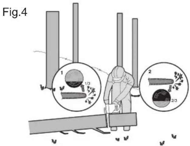
When the log is supported on one end, as illustrated in Figure 4, cut 1/3 the diameter from the underside (underbuck) (1). Then make the finished cut by overbucking (2) to meet the first cut.
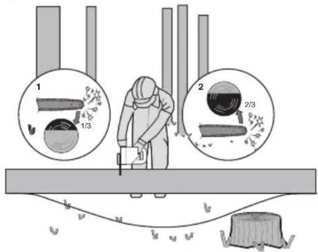
When the log is supported on both ends, as illustrated in Figure 5, cut 1/3 the diameter from the top (overbuck) (1). Then make the finished cut by underbucking (2) the lower 2/3 to meet the first cut.
Fig.5
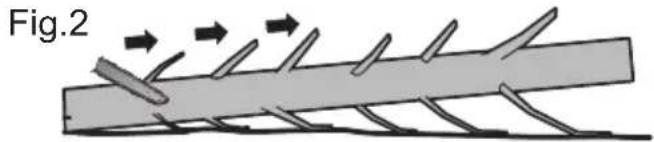
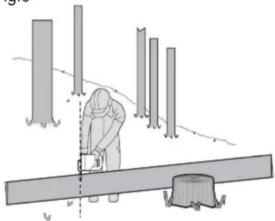
When bucking on a slope always stand on the uphill side of the log, as illustrated in Figure 6. When "cutting through", to maintain complete control release the cutting pressure near the end of the cut without relaxing your grip on the Chainsaw handles. Don't let the chain contact the ground. After completing the cut, wait for the saw chain to stop before you move the Chainsaw. Always stop the motor before moving from tree to tree.
Fig.6
natural_image
Illustration of a person using a tool on a wooden beam with tree stumps in the background (no text or symbols)SYMBOLS
 | To reduce the risk of injury, user must read instruction manual |
 | WARNING |
 | Wear ear protection |
 | Wear eye protection |
 | Wear dust mask |
 | Always use chain saw two-handed |
 | Beware of chain saw kickback and avoid contact with bar tip |
 | Wear head protection |
 | Wear protective gloves |
 | Li-lon battery. This product has been marked with a symbol relating to 'separate collection' for all battery packs and battery pack. It will then be recycled or dismantled in order to reduce the impact on the environment. Battery packs can be hazardous for the environment and for human health since they contain hazardous substances. |
 | |
 | Do not burn |
 | Batteries may enter water cycle if disposed improperly, which can be hazardous for ecosystem. Do not dispose of waste batteries as unsorted municipal waste. |
 | Waste electrical products must not be disposed of with household waste. Please recycle where facilities exist. Check with your local authorities or retailer for recycling advice. |
| Environmentally friendly disposal Old electrical appliances must not be disposed of together with the residual waste, but have to be disposed of separately. The disposal at the communal collecting point via private persons is for free. The owner of old appliances is responsible to bring the appliances to these collecting points or to similar collection points. With this little personal effort, you contribute to recycle valuable raw materials and the treatment of toxic substances. | |
 | Unlock |
 | Lock |

NOTE: Before using the tool, read the instruction book carefully.
ASSEMBLY

WARNING! Do not install the battery pack before it has been completely assembled.
Always use gloves when handling the chain.
CHAIN AND GUIDE BAR ASSEMBLY
- Unpack all parts carefully. Remove the drive cover by turning the hex nuts in a counter-clockwise direction. (See Fig. A1)
- Place the Chainsaw on a solid, level surface.
- Use only genuine Kress chains or those recommended for the Guide Bar.
- Slide the chain in the slot around the guide bar. Ensure the chain is in correct running direction by comparing it to the chain icon, or referring to the chain direction symbol found on the saw body.
- Fit the chain onto the drive sprocket, so that the two bar locating studs on the bar pad it into the keyway of the opening on the guide bar. Ensure that the chain tension hole its on the chain tension pin.(See Fig. A2).
- Assure all parts are seated properly and hold
chain and guide bar in a level position. Make sure the drive links are fully seated in the drive sprocket (See Fig. A3), avoiding a kink as shown in Fig. A4. If kink occurs, pick up on the chain at the guide bar just ahead of the kink and then pull the kink out.
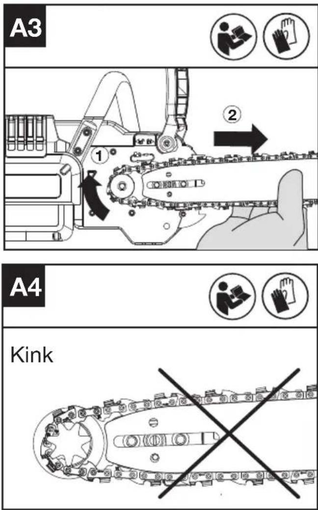
NOTE: Chain should rotate freely and be free of kinks.
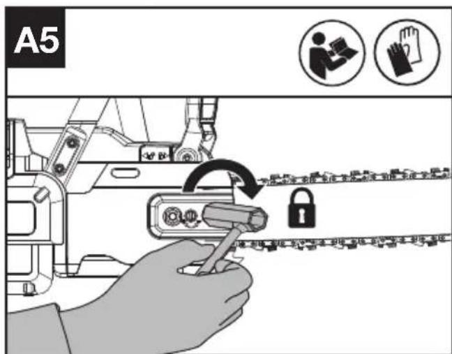
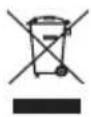
- Fit the drive cover and tighten the drive cover by turning the hex nuts clockwise until it is slightly tight. (See Fig. A5)
WARNING: The chain is not yet tensioned. Tensioning the chain applies as described under "TENSIONING CHAIN". The chain now needs to be inspected to make sure it is properly tensioned.
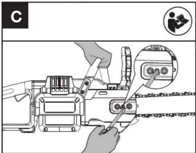
TENSIONING CHAIN (See Fig. B, C)
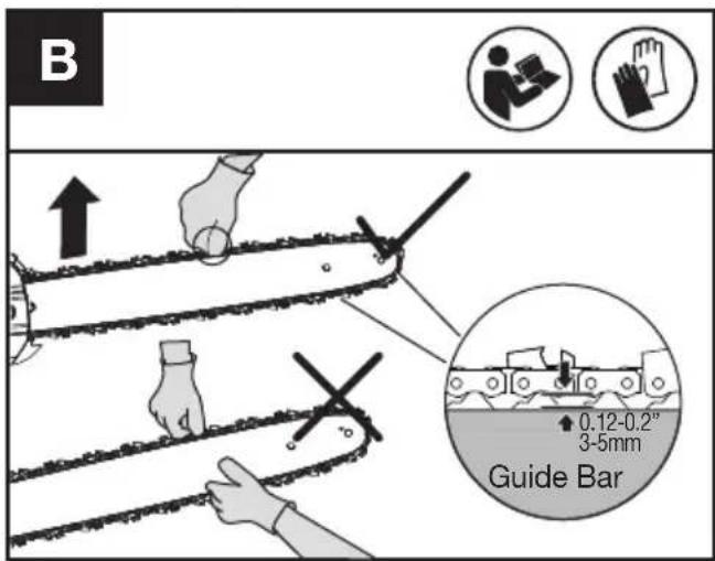
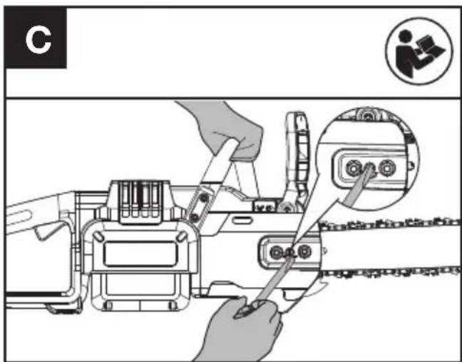
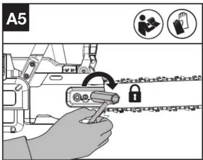
- Lossen the nuts on the guide cover with wrench as shown in Fig A1. But remember not to remove the cover.
- Lift the chain cover of guide bar and turn the tensioning screw with a wrench in a clockwise direction. Tighten the tensioning screw until the chain is tensioned correctly and can still move easily. (See Fig B&C)
- Tighten the nuts on the drive cover with wrench as shown in A5 until it is tight.
- Double check the tension set by the chain tensioning screw. The correct chain tension is reached when the chain can be raised approx. Half the drivelink depth from the guide bar in the center. This should be done by using one hand to raise the chain against the weight of the machine.
NOTE: The chain will stretch while cutting and lose proper tension. When the chain becomes loose, completely unscrew the hex nuts or turn the hex nuts around three full turns in a counter-clockwise direction, then re-tension the chain and tighten the hex nuts to properly reset the chain tension by
repeating Steps 1-4 listed above.

WARNING:
- Removing the battery pack before adjusting saw chain tension.
- Cutting edges on chain are sharp. Use protective gloves when handling chain.
- Maintain proper chain tension always. A loose chain will increase the risk of kickback. A loose chain may jump out of guide bar groove. This may injure operator and damage chain. A loose chain will cause chain, bar, and sprocket to wear rapidly.
NOTE: The chain is properly tensioned when it can be lifted off of the Guide Bar and the drivelink is within the rail of the Guide Bar.
LUBRICATION (See Fig. D)
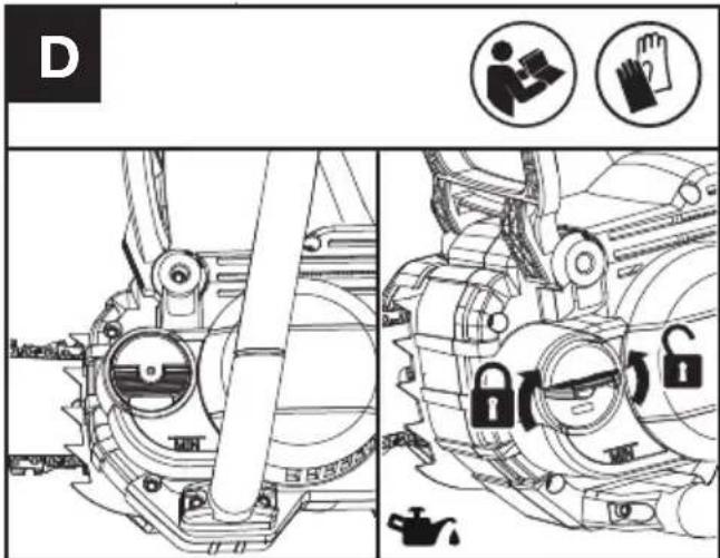

IMPORTANT: The Chainsaw is not filled with oil. It is essential to fill with oil before use. Never operate the Chainsaw without bar and chain oil or allow the tank to become empty, as this will result in extensive damage to the product.
NOTE: Chain life and cutting capacity depend on optimum lubrication. Therefore, the chain is automatically oiled during operation.
FILLING OIL TANK:

WARNING: Removing the battery pack before filling the oil tank.
- Set Chainsaw on any suitable surface with oil filler cap facing upward.
- Clean area around the oil filler cap with cloth and unscrew the cap by turning it counter clockwise.
- Add bar and chain oil until tank is full.
- Avoid dirt or debris entering oil tank, refit oil filler cap and tighten by turning clockwise until hand tight.

It is important to use bar and chain lubricant (not automotive oil) that is
formulated to perform over a wide temperature range with no dilution required. This can be found at the location where you purchased this saw or
your local hardware store. Do not use dirty, used or otherwise contaminated oils. Damage may occur to the bar or chain. Use of non approved oil will void the warranty.
Do not swallow any type of bar oil. If swallowed, call a physician immediately. Keep out of reach of children. Store away from heat or open flame.
CHECKING THE AUTOMATIC OILER
Proper functioning of the automatic oiler can be checked by running the Chainsaw and pointing the tip of the guide chain bar towards a piece of cardboard or paper on the ground. If an increasing oil pattern develops on the cardboard, the automatic oiler is operating fine. If there is no oil pattern, despite a full oil reservoir, contact Kress customer service agent or Kress approved service agent.
NOTE: It make take an extended period of time (1 minute +) for the pump to prime when new or after the saw has not been in use for an extended period of time.

CAUTION: Do not touch the ground with the chain. Ensure safety clearance of 6" (15 cm).
Checking the controls Throttle Lock-Out Button and Throttle Trigger
- Remove the battery.
- Try to press the Throttle Trigger. If the Throttle Trigger can be pressed, the Throttle Lock-Out Button is defective. Stop using the chainsaw and contact the service agent.
- Hold and press the Throttle Lock-Out Button first, then press the Throttle Trigger.
- Release the Throttle Trigger and the Throttle Lock-Out Button. If the Throttle Trigger or the Throttle Lock-Out Button is get stuck and cannot spring back to its original position. Stop using the chainsaw and contact the service agent.
OPERATION
WARNING! The charger and battery pack are specially designed to work together so
do not attempt to use any other devices. Never insert or allow metallic objects into your charger or battery pack connections because of an electrical failure and hazard will occur.
NOTE: Your battery pack is UNCHARGED and you must charge once before use.
The battery charger supplied is matched to the Li-ion battery installed in the machine. Do not use another battery charger.
CHECKING THE BATTERY CHARGE CONDITION (See Fig. E1)
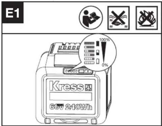
Before starting or after use, press the power test button on the battery pack to check the battery capacity.
Note: Fig E1 only applies for the battery pack with battery indicator light.
| Remarks LED light Battery condition | ||
| Five green lights are illuminated. | 80% ≤ Power level ≤ 100% | |
| Four green lights are illuminated. | 60% ≤ Power level < 80% | |
| Three green lights are illuminated. | 40% ≤ Power level < 60% | |
| Two green lights are illuminated. | 20% ≤ Power level < 40% | |
| One green light is illuminated. | 10% ≤ Power level < 20% | |
| One green light is flashing. | 0% ≤ Power level < 10% | |
CHARGING YOUR BATTERY PACK (See Fig. E2)
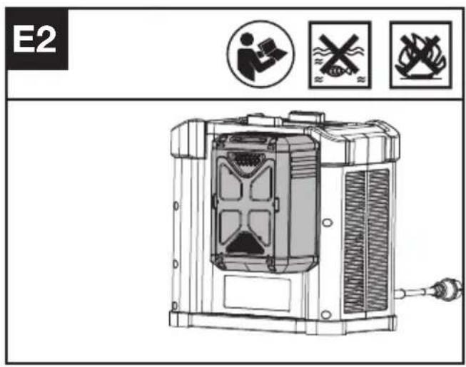
The Li-ion battery is protected against deep discharging. When the battery is empty, the machine is switched off by means of a protective circuit. Each battery must be fully charged before the first use.
TO REMOVE OR INSTALL BATTERY PACK (See Fig. F, G)
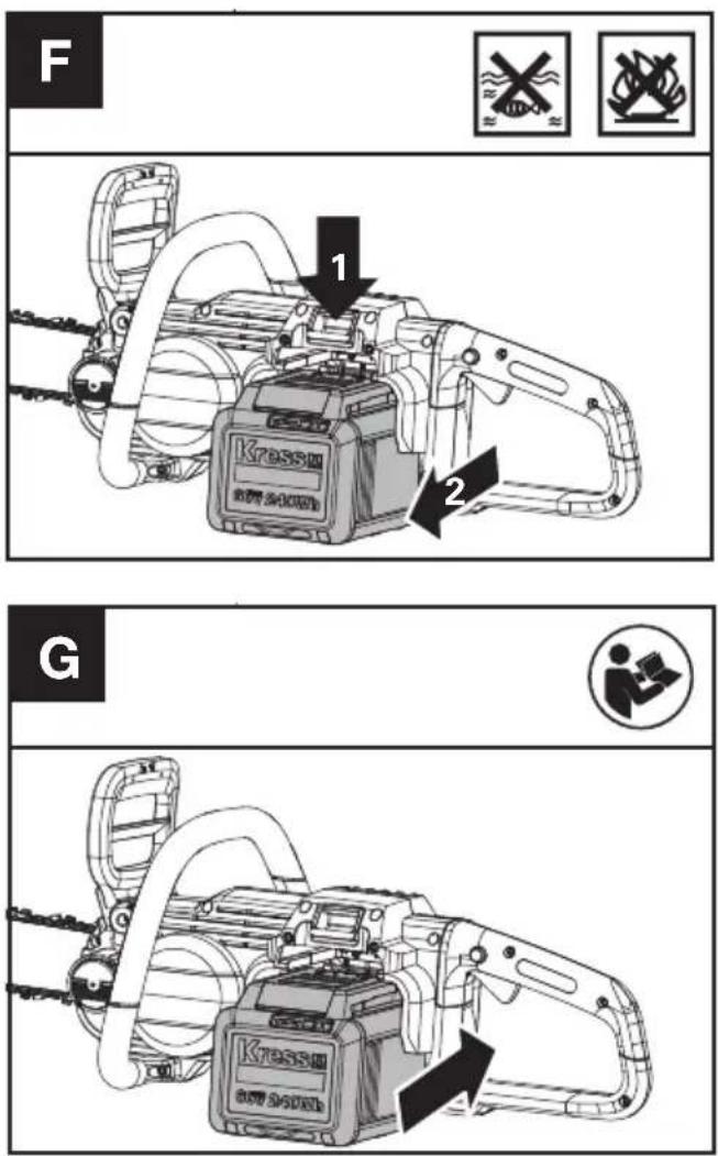
Depress the battery pack release button to remove the battery pack from your tool. After recharging, insert the battery pack into the battery port. A simple push and slight pressure will be sufficient until a click is heard. Check to see if the battery is fully secured. NOTE: When removing the battery pack, hold it firmly to avoid dropping and injury.
SWITCHING ON AND OFF (SEE FIG. H)
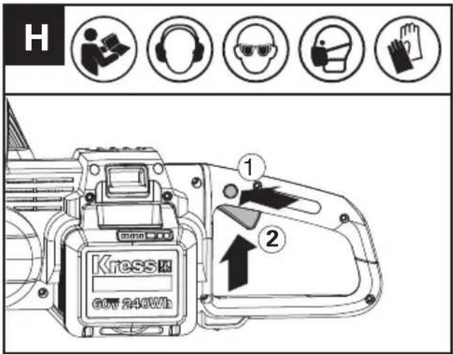
ATTENTION: Check the battery packs before using your cordless tool. Only use the battery pack listed in the accessories section.
To switch on the tool, press the throttle lock-out button, then fully press the throttle trigger and hold in this position. The throttle lock-out button can now be released. If the saw does not function, please see CHAIN BRAKE LEVER information below. For switching off, release the throttle trigger.
NOTE: The chain brake must be deactivate in order for the saw to be switched on.
CHAIN BRAKE LEVER (See Fig. I)
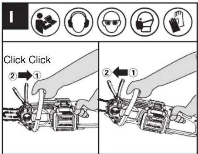
The chain brake lever is a safety mechanism activated through the front hand guard, when kickback occurs. Chain stops immediately.
The following function check should be carried out at regular intervals. Pull the front hand guard towards the operator (position ① to deactivate chain brake. To activate the chain brake, push front hand guard forwards (position ②
NOTE:
- If the saw is unable to start, even though it is assembled properly and working with fully charged
battery packs, then you should check if the chain brake lever is in the correct position (position ①). 2. *When the chain brake is activated, the saw chain should stop instantly. If the saw chain does not stop or take time to slow down, please stop using the chain saw and contact the service agent.
CUTTING
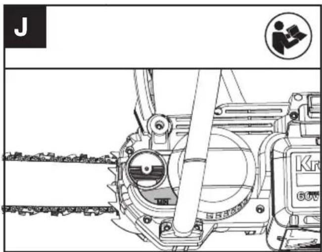
IMPORTANT: Is the oil tank filled? Check the Oil Level Window prior to starting and regularly during operation (See Fig. J). Refill oil when oil level is low. A full oil tank will last approx. 12 minutes of cutting depending on sawing intensity and stops. Check recent replaced chain tension about every 10 minutes during operation.
natural_image
Technical line drawing of a mechanical device with gear and shaft assembly (no text or symbols)(1) Installing the battery pack into the machine.
(2) Make sure section of log to be cut is not laying on the ground. if the log you are cutting is laying on the ground, do not cut completely through and allow the chain to make contact with the soil. Reposition the log for the final separating cut.
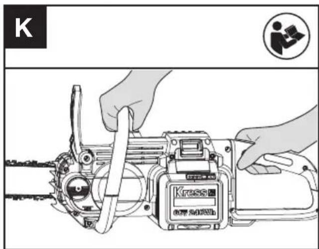
(3) Use both hands to grip saw. Always use left hand to grip front handle and right hand to grip rear handle. Use a firm grip. Thumbs and fingers must wrap around saw handles. (See Fig. K)
(4) Make sure your footing is firm. Keep feet-shoulder
width apart. Distribute your weight evenly on both feet.
(5) When ready to make a cut, push the throttle lock-out button completely in with the right thumb and squeeze the trigger. This will turn saw on. Releasing the trigger will turn the saw off. Make sure the saw is running at full speed before starting a cut.
(6) When starting a cut, slowly place moving chain against the wood. The wood should be as close to the saw body as possible. Hold saw firmly in place to avoid possible bouncing or skating (sideways movement) of the saw.
(7) Guide the saw using light pressure with your left forearm and do not put excessive force on the saw, letting the saw do its work. The motor will overload and can burn out. It will do the job better and safer at the rate for which it was intended.
(8) Remove the saw from a cut with the saw running at full speed. Stop the saw by releasing the throttle trigger. Make sure the chain has stopped before setting the saw down.
(9) Keep practicing on scrap logs in a secure working area until you are comfortable, using a fluid motion and a steady cutting rate.
KICKBACK SAFETY DEVICES ON THIS SAW
This saw has a low-kickback chain and reduced kickback Guide Bar. Both items reduce the chance of kickback. However, kickback can still occur with this saw.
The following steps will reduce the risk of kickback.
- Use both hands to grip saw while saw is running. Use firm grip. Thumbs and fingers must wrap around saw handles.
- Keep all safety items in place on saw. Make sure they work properly.
- Do not overreach or cut above shoulder height.
- Keep solid footing and balance at all times.
- Stand slightly to the left side of saw. This keeps your body from being in direct line with chain.
- Do not let Guide Bar nose tip touch anything when chain is moving.
- Never try cutting through two logs at same time. Only cut one log at a time.
- Do not bury the Guide Bar nose or try plunge cut (boring into wood using guide bar nose). This type of cutting is for properly trained professionals only.
- Watch for shifting of wood or other forces that may pinch chain.
- Use extreme caution when reentering a previous cut.
- Use only the low-kickback chain and guide bar that were supplied with this Chainsaw or or are recommended as a replacement.
- Never use a dull or loose chain. Keep chain sharp with proper tension.
HOW TO USE SAW SAFELY
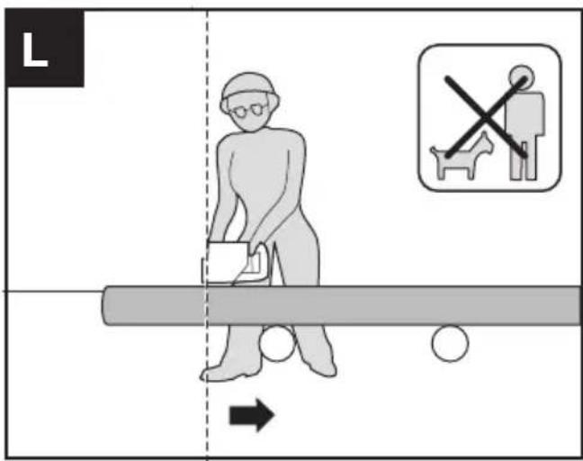
- Use the Chainsaw only with secure footing.
- Hold the Chainsaw at the right-hand side of your body (See Fig. L).
- The chain must be running at full speed before it makes contact with the wood.
- Use the bumper spikes to secure the saw onto the wood when starting to cut.
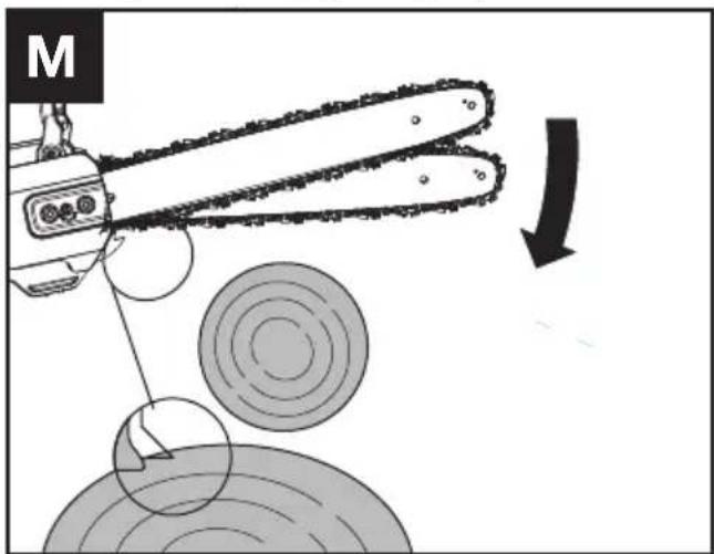
- Use the Bumper Spikes as a leverage point while cutting if necessary. (See Fig. M)
- Do not operate the Chainsaw with arms fully extended, attempt to saw areas which are difficult to reach, or stand on a ladder while sawing (See Fig. N).
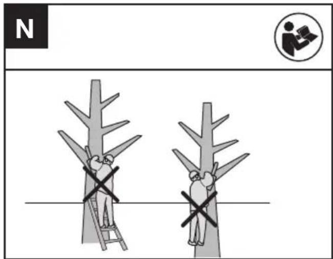
Never use the Chainsaw above shoulder height.
CUTTING WOOD UNDER TENSION (SEE
FIG. O)
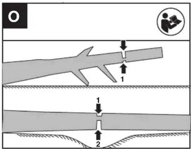
WARNING: When cutting a limb that is under tension, use extreme caution. Be alert for wood springing back. When wood tension is released, limb could spring back and strike operator causing severe injury or death.
When sawing logs supported on both ends, start the cut from above(1) about 1/3 of the diameter into the log (overbuck) and then finish the cut (2) from below, in order to avoid contact of the Chainsaw with the ground. When sawing logs supported on only one end, start the cut from below (1) about 1/3 of the diameter into the log (underbuck) and finish the cut from above (2) in order to avoid log splitting or jamming of the Chainsaw.
When cutting short sections (example of firewood), it is not normally necessary to perform the underbuck cut when the log is supported on one end.
For Battery tools
The recommended ambient temperature range for discharging is -20°C\~45°C(-4°F\~113°F).
The recommended ambient temperature range for the charging system during charging is -5^ 45^ ( 23^ 113^ ).
Low temperature use reminder :
To guarantee optimal performance and maintain the longevity of your battery system, please ensure that the battery is at normal room temperature before starting work in cold conditions.
TRANSPORTATION
Transporting the chainsaw
- Switch off the chainsaw and remove the battery.
- When transporting your chainsaw by hand, hold the front handle of chain sawto make sure that your machine is parallel to the ground.
- When transporting your chainsaw in a vehicle, secure and position it to prevent movement or damage.
Transporting the battery
-
Ensure the battery is in a safe condition.
-
Use non-conductive packaging when transporting the battery.
- The contained Li-Ion batteries are subject to the dangerous goods legislation requirements.
Transport batteries only when the battery housing is undamaged. Pack up the batteries in such a manner that cannot move around in the packaging.
SAW MAINTENANCE
Follow maintenance instructions in this manual. Proper cleaning of saw and chain and guide bar maintenance can reduce chances of kickback. Inspect and maintain saw after each use. This will increase the service life of your saw.Once got wet in the rain during operation, the machine and the battery pack should be dried before storing or charging.
NOTE: Even with proper sharpening, risk of kickback can increase with each sharpening.
MAINTENANCE AND STORAGE OF CHAINSAW
1. Remove the battery pack
- When not in use
• Before moving from one place to another - Before servicing
-
Before changing accessories or attachments, such as saw chain and guard
-
Inspect Chainsaw before and after each use. Check saw closely if guard or other part has been damaged. Check for any damage that may affect operator safety or operation of saw. Check for alignment or binding of moving parts. Check for broken or damaged parts. Do not use Chainsaw if damage affects safety or operation. Have damage repaired by authorized service center.
3. Maintain Chainsaw with care.
- Keep chain sharp, clean, and lubricated for better and safer performance.
- Follow steps outlined in this manual to sharpen chain.
- Keep handles dry, clean, and free of oil and grease.
-
Keep all screws and nuts tight.
-
When servicing, use only identical replacement parts.
5. When not in use, always store Chainsaw
- in a high or locked place, out of children's reach
- in a dry place
• with protective scabbard in place
BAR MAINTENANCE
To maximize bar life, the following bar maintenance is recommended.
The bar rails that carry the chain should be cleaned before storing the tool or if the bar or chain appear to be dirty.
The rails should be cleaned every time the chain is removed.
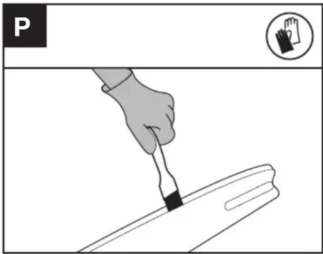
TO CLEAN THE BAR RAILS:
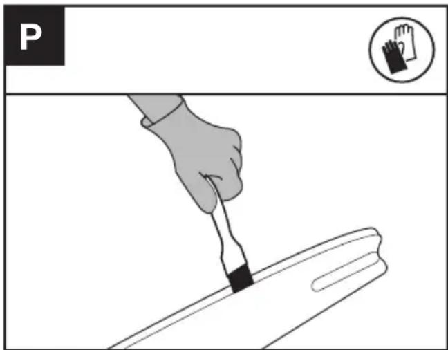
- Remove drive cover and bar and chain. (see section ASSEMBLY)
- Using a wire brush, screwdriver or similar tool, clear the residue from the inner groove of the bar. (See Fig. P)
- Make sure to clean oil passages thoroughly.
CONDITIONS WHICH REQUIRE CHAIN AND GUIDE BAR MAINTENANCE:
- Saw cuts to one side or at an angle.
- Saw has to be forced through the cut.
- Inadequate supply of oil to the bar and chain.
Check the condition of the guide bar each time the chain is sharpened. A worn guide bar will damage the chain and make cutting difficult.
After each use, remove the battery pack, clean all sawdust from the guide bar and sprocket hole.
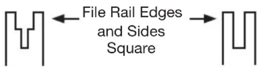
When rail top is uneven, use a flat file to restore square edges by removing any burrs from the side or top of the bar.
Worn Groove Correct Groove
Replace the guide bar when the groove is worn, the guide bar is bent or cracked, or when excess heating or burring of the rails occurs. If replacement is necessary, use only the guide bar specified for your saw in the repair parts list or on the decal located on the Chainsaw.
REPLACING BAR & CHAIN
Replace chain when cutters are too worn to sharpen or when the chain becomes inoperable. Only use replacement chain noted in this manual.
Inspect guide bar before sharpening chain. A worn or damaged guide bar is unsafe. A worn or damaged guide bar will damage chain. It will also make cutting harder.
LUBRICATE SPROCKET

WARNING: Wear heavy duty gloves when performing any maintenance or service to this tool. Always remove the battery pack before performing any service or maintenance on this tool.
NOTE: It is not necessary to remove the chain or bar when lubricating the guide bar sprocket.
- Clean the bar and sprocket
- Using a grease gun, insert the tip of the gun into the lubrication hole and inject grease until it appears at the outside edge of the sprocket tip. (See Fig. Q)
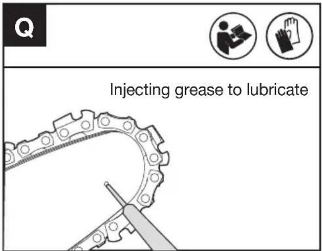
- To rotate the sprocket pull the chain by hand until the ungreased side of the sprocket is in line with the grease hole. Repeat the lubrication procedure.
SHARPENING SAW CHAIN

WARNING: Remove the battery pack before servicing. Severe injury or death could occur from electrical shock or body contact with moving chain.
Cutting edges on chain are sharp. Use protective gloves when handling chain.
Keep chain sharp. Your saw will cut faster and more safely. A dull chain will cause undue sprocket, Guide Bar, chain, and motor wear. If you must force chain into wood and cutting creates only sawdust with few large chips, chain is dull.
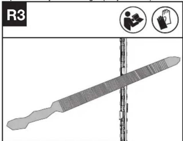
- Before sharpening, please pay attention of the following steps:(See Fig R1)
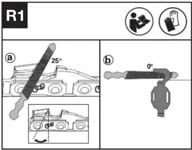
a: Filing angle; b: file position.
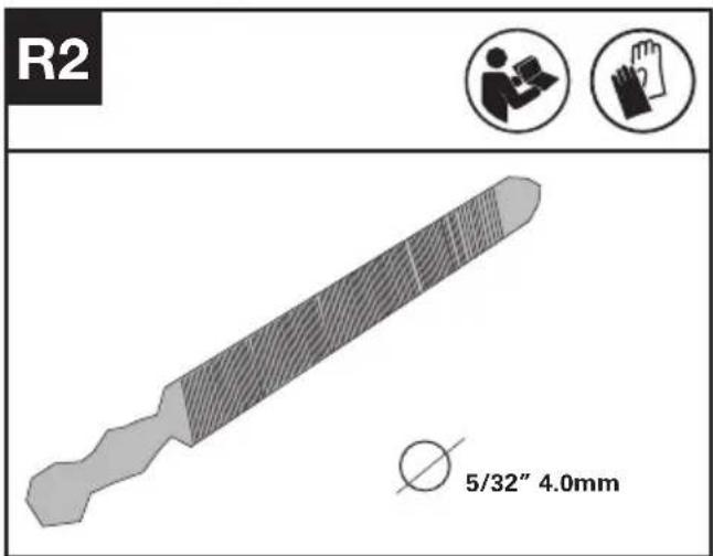
How to sharpen the cutters
- Prepare a round file to sharpen the cutters.(See Fig R2).Note: Firmly clamp the guide bar in a vice before sharpening the chain. Ensure that the chain is not "nipped" and can freely move on the guide bar. Check that the chain is properley tensioned. (See "Tensioning Chain" section).
- Sharpen the cutters with file from the inner side of cutting teeth towards the outside of the chain. (See Fig R3)
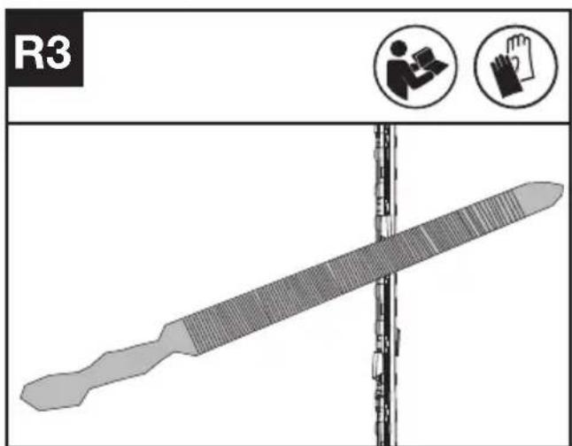
- File all the cutters on one side of the guide bar.
- Turn the chainsaw around and file all of the cutters on the opposite side.
- Ensure that the length of all cutting teeth is same. To ensure efficient, safe and smooth cutting, file the depth gauge height to 0.025" (0.65mm). Make sure that the leading edge of the depth gauge is rounded off.(See Fig R4)

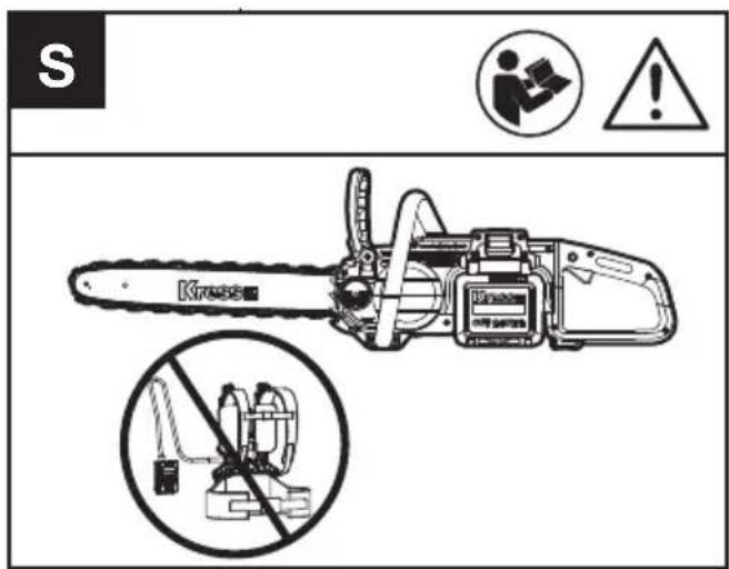
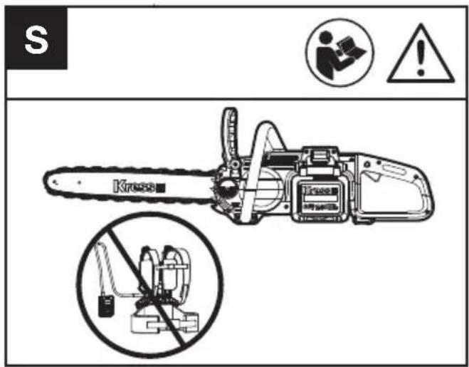
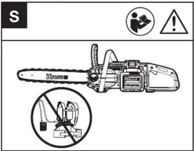
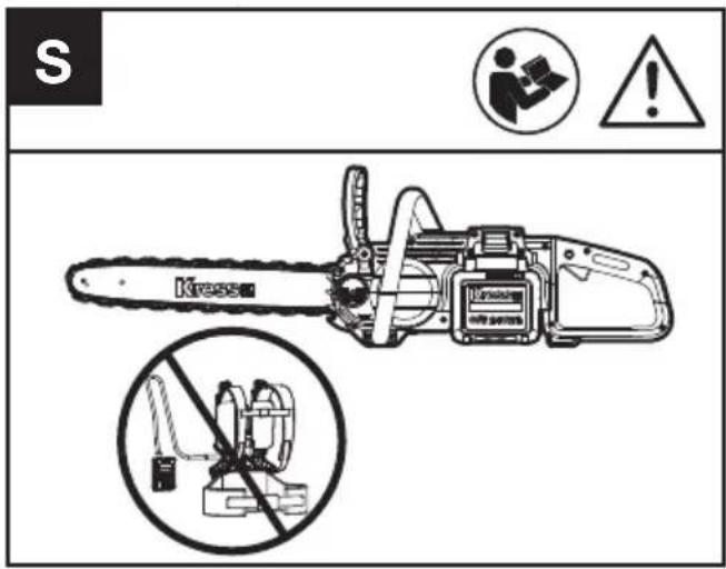
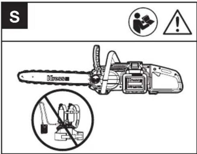
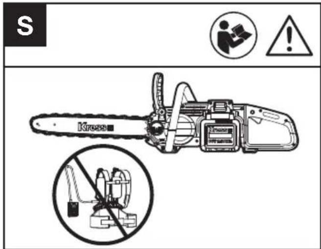
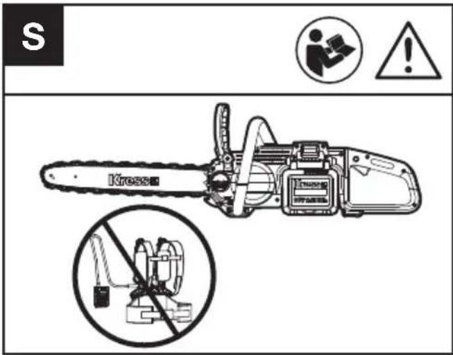
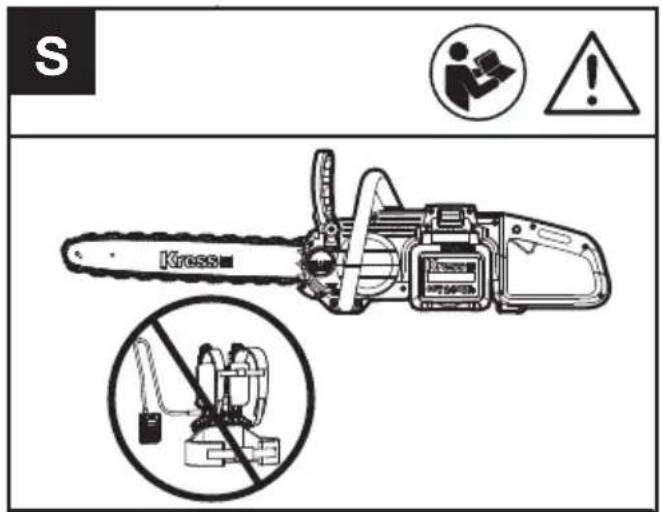
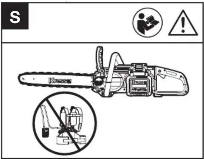
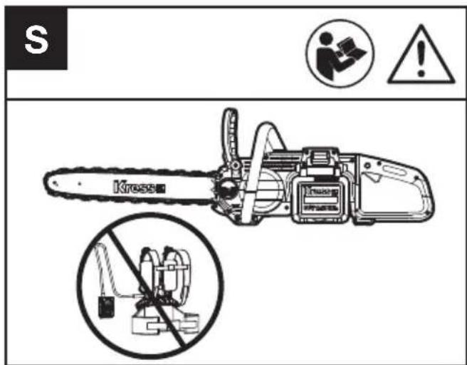
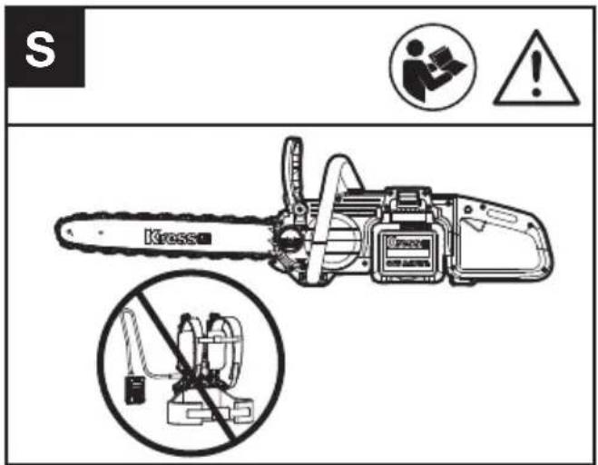
WARNING
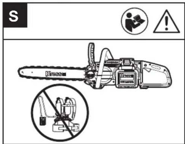
It is suggested not to use the chain saw with battery harness for your safety.
CLEANING
- Switch off the chainsaw and remove the battery.
- Do not use aggressive detergents or solvents. Clean the machine after use with a damp cloth dipped in mild detergent.
- Keep battery connection free of dirt and debris, and clean with a soft and dry brush or cloth.
- Do not spray water onto the motor and electrical components.
- Do not use pressure washer to clean your machine.
STORAGE
- Remove the battery pack from the chainsaw before storage.
- Store the chainsaw and the battery in a dry and secure place that is inaccessible to children and other unauthorized people. Remove the cutting attachment if no use for a long time.
- Store the battery only within a temperature range between 41 °F (5°C) and 77 °F (25°C). As an example, do not leave the battery in the car in summer time.
- Once got wet in the rain during operation, the machine and the battery should be dried before storing or charging. Remove the battery and reinsert it if the machine fails to turn on.
TROUBLESHOOTING TABLE
The following table gives checks and actions that you can perform if your machine does not operate correctly. If these do not identify/remedy the problem, contact your service agent.

WARNING: Switch off and remove plug from power source before investigating fault.
| Symptom Possible | Cause Remedy | |
| Chainsaw fails to operate Low battery charge. Chain brake not in the proper position. | Charge both the battery packs.Check to see if the chain brake is in position 1Refer to CHAIN BRAKE for details. | |
| Chainsaw operates intermittently | Applying too much pressure while cutting.Not operating saw at full speed.Over heatingLoose connection.Internal wiring defective.Throttle trigger defective. | Applying relatively less pressure while cutting.Place the machine in a cool, ventilated place to cool it down.Contact service agent.Contact service agent.Contact service agent. |
| Dry chain No oil in reservoir. | Oil passage clogged. | Refill oil.Clean oil passage outlet. |
| Kickback Brake/Run Down Brake | Brake does not stop chain Contact service agent. | |
| Chain/chain bar over-heats. | No oil in reservoir.Oil passage clogged.Chain is over tensioned.Dull chain. | Refill oil.Clean oil passage outlet.Adjust chain tension.Sharpen chain or replace. |
| Chainsaw rips, vibrates, does not saw properly. | Dull chain.Chain worn out.Chain teeth are facing in the wrong direction.Chain tension too loose. | Sharpen chain or replace.Replace chain.Reassemble with chain in correct direction.Adjust chain tension. |
BATTERY
| Problems Possible | Causes Corrective Action | |
| Error LED lit The battery is discharged | Charge the battery. If battery fails to charge, contact your Service Agent. | |
| Temperature issue. Use the battery in surroundings where temperatures are between -20°C and 45°C(-4°F~113°F). | ||
| Others Contact your Service Agent. |
TECHNICAL DATA
Type Designation KC300 KC300.X (3 - designation of machinery, representative of Chainsaw)
| KC300 KC300.X** | |
| Rated voltage 60 V Max. *** | --- |
| Bar length 40 cm | |
| Chain speed 24 m/s | |
| Oil tank capacity 190 ml | |
| Chain pitch 0.325'' LP | |
| Degree of protection IPX4 | |
| Machine weight( without battery, or bar & chain) 3.7kg |
** X may be followed by one or two characters. All models are the same except model number and trademark. The suffix in models may be number from "1" to "999" or English letter "A" to "Z" or "M1" to "M9" which means different package or the various of accessories packed in the package.
*** Voltage measured without workload. Initial battery voltage reaches maximum of 60 volts. Nominal voltage is 54 volts.
SUGGESTED BATTERIES AND CHARGERS
| EN | Battery Amp Charger Amperage | |||
| KAC804 4 Ah KAC840 | 30 A | |||
We recommend that you purchase your accessories from the same Dealer that sold you the tool. Refer to the accessory packaging for further details. Your Dealer can assist you and offer advice.
COMBINATIONS OF CUTTING ATTACHMENTS
| Cutting attachment |
| KAC331-16" Guide Bar |
| KAC301-16" 0.325" LP Saw Chain |
| KAC330-14" Guide Bar |
| KAC300-14" 0.325" LP Saw Chain |
TECHNICAL DATA FOR BATTERY PACK (OPTIONAL)
| Frequency bands for Bluetooth | 2400-2483.5 MHz |
| Maximum Transmitted Power for Bluetooth | 8 dBm |
NOISE DATA
| A weighted sound pressure | L_pA = 88 dB(A) K_pA = 3.0 dB(A) |
| A weighted sound power | L_wA = 99 dB(A) K_pA = 3.0 dB(A) |
| Wear ear protection. |
VIBRATION INFORMATION
Vibration total values (triax vector sum) determined according to EN 62841:
| Vibration emission value | a_h < 3.6 m/s^2 |
| uncertaintyK=1.5m/s2 |
The declared vibration total value and the declared noise emission value have been measured in accordance with a standard test method and may be used for comparing one tool with another.
The declared vibration total value and the declared noise emission value may also be used in a preliminary assessment of exposure.

WARNING: The vibration and noise emissions during actual use of the power tool can differ
from the declared value depending on the ways in which the tool is used especially what kind of workpiece is processed dependant on the following examples and other variations on how the tool is used:
How the tool is used and the materials being cut or drilled.
The tool being in good condition and well maintained. The use of the correct accessory for the tool and ensuring it is sharp and in good condition.
The tightness of the grip on the handles and if any anti vibration and noise accessories are used.
And the tool is being used as intended by its design and these instructions.
This tool may cause hand-arm vibration syndrome if its use is not adequately managed.

WARNING: To be accurate, an estimation of exposure level in the actual conditions of use
should also take account of all parts of the operating cycle such as the times when the tool is switched off and when it is running idle but not actually doing the job. This may significantly reduce the exposure level over the total working period.
Helping to minimise your vibration and noise exposure risk.
Always use sharp chisels, drills and blades.
Maintain this tool in accordance with these instructions and keep well lubricated (where appropriate).
If the tool is to be used regularly then invest in anti vibration and noise accessories.
Plan your work schedule to spread any high vibration tool use across a number of days
DECLARATION OF CONFORMITY
We,
Positec Germany GmbH
Postfach 32 02 16, 50796 Cologne, Germany
On behalf of Positec declare that the product
Description: Battery-powered chainsaw
Type: KC300 KC300.X (3 - designation of machinery, representative of chainsaw)
Function: Cutting wood
Complies with the following Directives:
2006/42/EC, 2014/30/EU, 2011/65/
EU&(EU)2015/863, 2000/14/EC amended by 2005/88/EC
The notified body involved
2000/14/EC amended by 2005/88/EC:
- Conformity Assessment Procedure as per Annex V
- Measured Sound Power Level 99.0dB(A)
- Declared Guaranteed Sound Power Level 102dB(A)
Standards conform to:
EN 62841-1, EN 62841-4-1, EN ISO 3744, EN IEC 55014-1, EN IEC 55014-2
The person authorized to compile the technical file, Name: Marcel Filz
Address: Positec Germany GmbH
Postfach 32 02 16, 50796 Cologne, Germany


2022/11/16
Allen Ding
Deputy Chief Engineer, Testing & Certification
Positec Technology (China) Co., Ltd.
18, Dongwang Road, Suzhou Industrial
Park, Jiangsu 215123, P. R. China
DECLARATION OF CONFORMITY
We,
Positec (UK & Ireland) Ltd
PO Box 6242, Newbury, RG14 9LT, UK
On behalf of Positec declare that the product
Description: Battery-powered chainsaw
Type: KC300 KC300.X (3 - designation of machinery, representative of chainsaw)
Function: Cutting wood
Complies with the following regulations:
Supply of Machinery (Safety) Regulations 2008
Electromagnetic Compatibility Regulations 2016
The Restriction of the Use of Certain Hazardous
Substances in Electrical and Electronic
Equipment Regulations
Noise Emission in the Environment by Equipment for Use Outdoors Regulations
- Conformity Assessment Procedure as per SCHEDULE 8
- Measured Sound Power Level 99.0dB(A)
- Declared Guaranteed Sound Power Level 102dB(A)
The notified body involved
Standards conform to:
BS EN 62841-1, BS EN 62841-4-1, BS EN ISO
3744, BS EN IEC 55014-1, BS EN IEC 55014-2
The person authorized to compile the technical file,
Name Jim Kirkwood
Address Positec (UK & Ireland) Ltd
PO Box 6242, Newbury, RG14 9LT, UK

UK CA
2022/11/16
Allen Ding
Deputy Chief Engineer, Testing & Certification
Positec Technology (China) Co., Ltd.
18, Dongwang Road, Suzhou Industrial
Park, Jiangsu 215123, P. R. China
INHALTSVERZEICHNIS
EINFÜHRUNG......25
KOMPONENTEN 27
4. Entasten
natural_image
Diagram of a mechanical or structural component with directional arrows indicating movement, labeled Fig.2 (no text or symbols on the diagram itself)natural_image
Illustration of a person using a tool on a wooden beam with tree stumps, no text or symbols presentSYMBOLE
natural_image
Technical line drawing of a mechanical device with gear and shaft components (no readable text or symbols)natural_image
Illustration of a hand using a tool to cut a piece of paper or paper (no text or symbols present)a:Feilwinkel; b:Feilenposition.
ACHTUNG
EU&(EU)2015/863, 2000/14/EC amended by 2005/88/EC
18, Dongwang Road, Suzhou Industrial
Park, Jiangsu 215123, P. R. China
SOMMAIRE
INTRODUCTION....49
LISTE DES COMPOSANTS....51
SÉCURITÉ DU PRODUIT....52
MONTAGE ET UTILISATION....59
TRANSPORT....65
ENTRETIEN DE LA TRONÇONNEUSE....65
NETTOYAGE....68
RANGEMENT....68
GUIDE DE DÉPANNAGE....69
CARACTÉRISTIQUES TECHNIQUES ....70
DÉCLARATION DE CONFORMITÉ....71
INTRODUCTION
Cher Client,


LISTE DES COMPOSANTS
-
CHAÎNE
-
GUIDE DE CHAINE
-
LEVIER DU FREIN DE CHAÎNE (PROTÈGE-MAIN)
-
POIGNÉE AVANT
-
VERROU DE PACK BATTERIE
-
BOUTON DE VERROUILLAGE
-
POIGNÉE ARRIÈRE
-
PROTECTION DE MAIN ARRIÈRE
-
INTERRUPTEUR MARCHE/ARRÊT/AMORCE
-
PACK BATTERIE *
-
JAUGE DU NIVEAU DE L'HUILE
-
BOUCHON DU RÉSERVOIR D'HUILE
-
GRIFFE DE BUTÉE
-
CAPOT D'ENTRAÎNEMENT
-
ÉCROUS HEXAGONAUX
-
VIS DE TENSION DE LA CHAÎNE
-
SYMBOLE SENS DE ROTATION ET DE COUPE
-
BUSE D'HUILE
-
GOUJONS D'EMPLACEMENT DE GUIDE
-
BARRE DE SERRAGE
-
PIGNON DE CHAÎNE
-
FOURREAU DE PROTECTION
-
CLÉ (VOIR FIG. A1)
-
PLAQUE DE TENSION DE LA CHAÎNE
-
TROU DE TENSION DE LA CHAÎNE (VOIR FIG. A2)
4. Ebranchage
natural_image
Diagram of a mechanical or structural component with directional arrows indicating movement, labeled Fig.2 (no text or symbols on the diagram itself)natural_image
Illustration of a person using a saw to cut tree bark, with no text or symbols presentSYMBOLES
natural_image
Technical line drawing of a mechanical device with chains and gears, no visible text or symbolsAVERTISSEMENT
INFORMATIONS RELATIVES AU BRUIT
INFORMATIONS RELATIVE AUX VIBRATIONS
DÉCLARATION DE CONFORMITÉ
We,
Positec Germany GmbH
Postfach 32 02 16, 50796 Cologne, Germany
18, Dongwang Road, Suzhou Industrial
Park, Jiangsu 215123, P. R. China
INDICE
INTRODUZIONE....72
ELENCO DEI COMPONENTI....74
SICUREZZA DEL PRODOTTO....75


ELENCO DEI COMPONENTI
4. Sramatura
natural_image
Diagram of a mechanical or fluidic component with directional arrows indicating flow or movement (no text or symbols)natural_image
Illustration of a person using a saw to cut tree bark, with no text or symbols presentSIMBOLI
natural_image
Technical line drawing of a mechanical device with gear and shaft assembly (no text or symbols)natural_image
Illustration of a hand using a tool to cut a piece of paper or paper (no text or symbols present)AVVERTENZAL
EU&(EU)2015/863, 2000/14/EC amended by 2005/88/EC
18, Dongwang Road, Suzhou Industrial
Park, Jiangsu 215123, P. R. China
TABLA DE CONTENIDOS
4. Poda
natural_image
Diagram of a mechanical or structural component with directional arrows indicating movement, labeled Fig.2 (no text or symbols on the diagram itself)natural_image
Illustration of a person using a tool to cut tree bark with a wooden log, no text or symbols presentSÍMBOLOS
natural_image
Technical line drawing of a mechanical device with chains and a worker icon (no readable text or symbols)natural_image
Illustration of a hand using a tool to cut a piece of paper or paper (no text or symbols present)ADVERTENCIA
18, Dongwang Road, Suzhou Industrial
Park, Jiangsu 215123, P. R. China
ÍNDICE
INTRODUÇÃO....118
LISTADE COMPONENTES....120
SEGURANÇA DO PRODUTO....121
* Not all the accessories illustrated or described are included in standard delivery.
SEGURANÇA DO PRODUTO AVISOS GÉRAIS DE SEGURANÇA DE FERRAMENTAS ELÉCTRICAS
4. Desgalhar
natural_image
Diagram of a mechanical or structural component with directional arrows indicating flow or movement (no text or symbols)
natural_image
Illustration of a person cutting wood with a saw, surrounded by tree stumps and a wooden plank (no text or symbols)SÍMBOLOS
natural_image
Technical line drawing of a mechanical device with chains and gears, no visible text or symbolsnatural_image
Illustration of a hand using a tool to cut a piece of paper or paper (no text or symbols present)How to sharpen the cutters
ATENÇÃO
18, Dongwang Road, Suzhou Industrial
Park, Jiangsu 215123, P. R. China
INHOUDSOPGAVE
INLEIDING....141
ONDERDELENLIJST 143
PRODUCTVEILIGHEID 144
ASSEMBLAGE EN BEDIENING ....151
VERVOER....157
ZAAG ONDERHOUD 157
REINIGEN....160
OPSLAG....160
PROBLEMEN OPLOSSEN....161
PRODUCTVEILIGHEID ALGEMENE VEILIGHEIDSWAARSCHUWINGEN VOOR VERMOGENSMACHINE
natural_image
Diagram of a mechanical or fluidic component with directional arrows indicating flow or movement (no text or symbols)5. Boomstam in stukken zagen
natural_image
Illustration of a person using a tool to cut tree bark from a wooden beam, with no visible text or symbols.SYMBOLEN
- Removing the battery pack before adjusting saw chain tension.
- Cutting edges on chain are sharp. Use protective gloves when handling chain.
- Maintain proper chain tension always. A loose chain will increase the risk of kickback. A loose chain may jump out of guide bar groove. This may injure operator and damage chain. A loose chain will cause chain, bar, and sprocket to wear rapidly.
natural_image
Technical line drawing of a mechanical device with chains and a worker icon (no readable text or symbols)natural_image
Illustration of a hand using a tool to cut a flat surface, with a circular icon showing a hand holding gloves (no text or symbols)a:Vijlhoek; b:vijlpositie.
WAARSCHUWING
| Accupack Amp Lader Amperage | ||
| KAC804 4 Ah KAC840 30 A |
18, Dongwang Road, Suzhou Industrial
Park, Jiangsu 215123, P. R. China
TARTALOMJEGYZÉK
BEVEZETŐ....164
AZ ALKATRÉSZEK LISTÁJA 166


4. Fák metszése
natural_image
Diagram of a mechanical or structural component with directional arrows indicating movement, labeled Fig.2 (no text or symbols on the diagram itself)5. Rönk aprítása
natural_image
Illustration of a person using a saw to cut tree bark, with no text or symbols presentSZIMBÓLUMOK
natural_image
Technical line drawing of a mechanical device with chains and gears, no visible text or symbolsMEGJEGYZÉS
18, Dongwang Road, Suzhou Industrial
Park, Jiangsu 215123, P. R. China
CUPRINS
INTRODUCERE....187
LISTADE COMPONENTE....189
INSTRUCTIUNIORIGINALE....190
ASAMBLARE ŞI OPERARE....197
TRANSPORTUL....203
ÎNTRETINEREA FERĂSTRĂULUI....203
CURĂȚAREA....206
DEPOZITAREA....206
DEPANAREA....207
DATE TEHNICE....208
DECLARAȚIE DE CONFORMITATE....209
NTRODUCERE
Stimate Client,


LISTA DE COMPONENTE
| 1.LANT DE FERĂSTRĂU | |
| 2.LAMĂ DE GHIDARE | |
| 3.MANETA FRÂNEI LANTULUI (APĂRĂTOARE DE MÂNĂ) | |
| 4.MÂNER FRONTAL | |
| 5.BUTON DE ELIBERARE A ACUMULATORULUI | |
| 6.BUTON DE BLOCARE | |
| 7.MÂNER POSTERIOR | |
| 8.APĂRĂTOARE MÂNĂ POSTERIOARĂ | |
| 9.ÎNTRERUPĂTOR PORNIRE/OPRIRE | |
| 10.ACUMULATOR * | |
| 11.FEREASTRĂ NIVEL DE ULEI | |
| 12.CAPACUL REZERVORULUI DE ULEI | |
| 13.GHEARĂ DE AMORTIZARE | |
| 14.CAPAC SISTEM DE ACTIONARE | |
| 15.PIULITE HEXAGONALE | |
| 16.ŞURUB PENTRU TENSIONAREA LANTULUI | |
| 17.SIMBOL PENTRU DIRECTIA DE DEPLASARE A LANTULUI | |
| 18.DUZĂ DE ULEI | |
| 19.BOLTURI DE LOCALIZARE BARĂ | |
| 20.CLEMĂ DE PRINDERE PENTRU LAMA DE GHIDARE | |
| 21.ROATĂ DE LANT | |
| 22.TEACĂ DE PROTECTIE | |
| 23.CHEIE (A SE VEDEA FIG. A1 ) | |
| 24.ŞTIFT PENTRU TENSIONAREA LANTULUI | |
| 25.ORIFICIU PENTRU TENSIONAREA LANTULUI (A SE VEDEA FIG. A2) |
4. Tăierea crengilor
natural_image
Diagram of a mechanical or structural component with directional arrows indicating flow or movement (no text or symbols)natural_image
Illustration of a person using a saw to cut tree bark, with no text or symbols presentSIMBOLURI
Frâna de siguranță este un mecanism de protectie,
natural_image
Technical line drawing of a mechanical device with gear and shaft components (no text or symbols)AVERTISMENT
EU&(EU)2015/863, 2000/14/EC amended by 2005/88/EC
Organismul notificat implicat
Nume: Intertek Deutschland GmbH (organism notificat 0905)
18, Dongwang Road, Suzhou Industrial
Park, Jiangsu 215123, P. R. China
SPIS TREŚCI
WPROWADZENIE....210
LISTAKOMPONENTÓW....212
BEZPIECZEŃSTWOPRODUKTU....213
MONTAŻ I OBSŁUGA....220
TRANSPORT....226
KONSERWACJA PIŁY....226
CZYSZCZENIE 229
PRZECHOWYWANIE....229
ROZWIAZYWANIE PROBLEMÓW....230
DANE TECHNICZNE....231
PL DEKLARACJA ZGODNOŚCI....232
WPROWADZENIE
Drogi kliencie,


LISTA KOMPONENTÓW
| 1.ŁAŃCUCH | |
| 2.PROWADNICA | |
| 3.DŹWIGNIA HAMULCA ŁAŃCUCHA (OSŁONA RĘKI) | |
| 4.UCHWYT PRZEDNI | |
| 5.ZATRZASK POJEMNIKA BATERYJNEGO | |
| 6.PRZYCISK BLOKOWANIA | |
| 7.TYLNY UCHWYT | |
| 8.OSŁONA TYLNEGO UCHWYTU | |
| 9.PRZEŁĄCZNIK WŁĄCZENIA/WYŁĄCZENIA | |
| 10.ZESTAW BATERII* | |
| 11.WSKAŹNIK POZIOMU OLEJU | |
| 12.NASADKA NAPEŁNIANIA OLEJU | |
| 13.KOLEC ZDERZAKA | |
| 14.OSŁONA NAPEĘDU | |
| 15.NAKRĘTKI SZEŚCIOKĄTNE | |
| 16.ŚRUBA NAPIĘCIA ŁAŃCUCHA | |
| 17.SYMBOL KIERUNKU PRZESUWU ŁAŃCUCHA | |
| 18.WYLOT OLEJU | |
| 19.KOŁKI USTALAJĄCE PROWADNICY | |
| 20.ZACISK PROWADNICY | |
| 21.ZĘBATKA NAPEĘDU | |
| 22.POCHWA OCHRONNA | |
| 23.KLUCZ (PATRZ RYS. A1) | |
| 24.SWORZEŃ NAPINACZA ŁAŃCUCHA | |
| 25.OTWÓR NACIĄGU ŁAŃCUCHA (PATRZ RYS. A2) |
4. Okrzesywanie
natural_image
Diagram of a mechanical or structural component with directional arrows indicating movement, labeled Fig.2 (no text or symbols on the diagram itself)5. Przerzynka pnia
natural_image
Illustration of a person using a saw to cut tree bark, with no text or symbols presentSYMBOLE
NOTE: Chain life and cutting capacity depend on optimum lubrication. Therefore, the chain is automatically oiled during operation.
NAPEŁNIENIE ZBIORNIKA OLEJU:

natural_image
Technical line drawing of a mechanical device with chains and gears, no visible text or symbolsTransport akumulatora
ABY WYCZYŚCIĆ SZYNY PROWADNICY:
OSTRZEŻENIE
18, Dongwang Road, Suzhou Industrial
Park, Jiangsu 215123, P. R. China
OBSAH
ÚVOD....233
SEZNAM KOMPONENTÜ....235
PŮVODNÍ NÁVOD K POUŽÍVÁNÍ......236
SESTAVENÍ APOUŽÍVÁNÍ 243
PŘEPRAVA....249
ÚDRŽBA PILY 249
ČIŠTĚNÍ......252
SKLADOVÁNÍ 252
ODSTRAŇOVÁNÍ PROBLÉMŮ 253
TECHNICKÉ ÚDAJE....254
PROHLÁŠENÍ O SHODĚ 255
ÚVOD
Vážený zákazníku,

SEZNAM KOMPONENTŮ
| 1.ŘETĚZ |
| 2.LIŠTA |
| 3.PÁKA BRZDY ŘETĚZU (OCHRANA RUKY) |
| 4.PŘEDNÍ DRŽADLO |
| 5.UVOLŇOVACÍ TLAČÍTKO BATERIE |
| 6.TLAČÍTKO ODJIŠTĚNÍ |
| 7.ZADNÍ DRŽADLO |
| 8.KRYT ZADNÍ RUKOJETI |
| 9.SPÍNAČ/SPOUŠŤ |
| 10.AKUMULÁTOR * |
| 11.MĚRKA OLEJE |
| 12.UZÁVĚR OLEJOVÉ NÁDRŽKY |
| 13.HROTOVÝ DORAZ |
| 14.KRYT POHONU |
| 15.ŠESTIHRANNÉ MATICE |
| 16.NAPÍNACÍ ŠROUB ŘETĚZU |
| 17.SYMBOL SMĚRU BĚHU A ŘEZU |
| 18.OLEJOVÁ TRYSKA |
| 19.VÝSTUPKY PRO POLOHOVÁNÍ LIŠTY |
| 20.UPÍNACÍ SVORKA LIŠTY |
| 21.ŘETĚZOVÉ KOLO |
| 22.OCHRANNÉ POUZDRO |
| 23.KLÍČ (VIZ OBR A1) |
| 24.KOLÍK K NAPNUTÍ ŘETĚZU |
| 25.OTVOR PRO NAPNUTÍ ŘETĚZU (VIZ OBR. A2) |
TYTO POKYNY USCHOVEJTE
4. Odvětvení
natural_image
Diagram of a mechanical or structural component with directional arrows indicating movement, labeled Fig.2 (no text or symbols on the diagram itself)natural_image
Illustration of a person using a saw to cut a tree stump, with no text or symbols present.SYMBOLY
natural_image
Technical line drawing of a mechanical device with gear and shaft components (no text or symbols)natural_image
Illustration of a hand using a tool to cut a piece of paper or paper (no text or symbols present)VAROVÁNÍ

18, Dongwang Road, Suzhou Industrial
Park, Jiangsu 215123, P. R. China
TABLE OF CONTENTS
ÚVOD....256
ZOZNAMSÚČASTÍ......258
PÔVODNÝ NÁVOD NA POUŽITIE....259
MONTÁŽAOBSLUHA....266
PREPRAVA....272
ÚDRŽBA PÍLY 272
ČISTENIE 275
SKLADOVANIE....275
ODSTRAŇOVANIEPROBLÉMOV....276
TECHNICKÉPARAMETRE....277
SK
PREHLÁSENIE O ZHODE....278
ÚVOD
Vážený zákazník,


ZOZNAM SÚČASTÍ
| 1.REŤAZ |
| 2.LIŠTA S PÍLOVOU REŤAZOU |
| 3.PÁKA BRZDY REŤAZE (OCHRANNÝ KRYT RUKY) |
| 4.PREDNÁ RUKOVÄŤ |
| 5.UVOLŇOVACÍ TLAČÍTKO BATERIE |
| 6.ODISTOVACIE TLAČIDLO |
| 7.ZADNÁ RUKOVÄŤ |
| 8.KRYT ZADNEJ RUKOVÄTE |
| 9.VYPÍNAČ ON/OFF |
| 10.BATÉRIOVÝ * |
| 11.UKAZOVATEL’ HLADINY OLEJA |
| 12.UZÁVER PLNIACEHO OTVORU OLEJA |
| 13.HROTOVÝ DORAZ |
| 14.KRYT POHONU |
| 15.ŠESTHRANNÉ MATICE |
| 16.SKRUTKA NAPÍNANIA REŤAZE |
| 17.ZNAČKA UKAZUJÚCA SMER OTÁČANIA A PÍLENIA |
| 18.OTVOR NA VYPÚŠŤANIE OLEJA |
| 19.KOLÍKY UMIESTNENIA LIŠTY |
| 20.UPÍNACIA SVORKA LIŠTY |
| 21.HNACIE REŤAZOVÉ KOLESO |
| 22.OCHRANNÉ PUZDRO |
| 23.KLÚČ NA MATICE (POZRITE SI OBR. A1) |
| 24.KOLÍK NAPÍNANIA REŤAZE |
| 25.OTVOR NAPÍNANIA REŤAZE (POZRITE OBR. A2) |
TIETO POKYNY USCHOVAJTE
ails, staples and wire from the tree.
2. Vypílenie záseku
natural_image
Diagram of a mechanical or fluidic component with directional arrows indicating flow or movement (no text or symbols)natural_image
Illustration of a person using a saw to cut tree bark, with no text or symbols presentSYMBOLY
natural_image
Technical line drawing of a mechanical device with chains and gears, no visible text or symbolsnatural_image
Illustration of a hand using a tool to cut a flat surface, with a circular icon showing a hand holding a glove (no text or symbols)VAROVANIE
18, Dongwang Road, Suzhou Industrial
Park, Jiangsu 215123, P. R. China
KAZALO VSEBINE
UVOD....279
SESTAVNI DELI....281
ORIGINALINSTRUCTIONS....282
SESTAVLJANJE IN NAČIN UPORABE....289
TRANSPORT....295
VZDRŽEVANJE ŽAGE....295
ČIŠČENJE 297
SHRANJEVANJE 297
ODPRAVLJANJE NAPAK....298
TEHNIČNI PODATKI....299
IZJAVA O SKLADNOSTI....300
UVOD
Spoštovana stranka,


SESTAVNI DELI
| 1.VERIGA |
| 2.LETEV |
| 3.ZAVORNI ROČAJ ZA VERIGO (VAROVALO ROKE) |
| 4.SPREDNJI ROČAJ |
| 5.GUMB ZA SPROSTITEV AKUMULATORJA |
| 6.GUMB ZA ZAKLEPANJE |
| 7.ZADNJI ROČAJ |
| 8.VAROVALO ZADNJEGA ROČAJA |
| 9.VKLOPNO/IZKLOPNO STIKALO |
| 10.AKUMULATOR * |
| 11.OKENCE ZA PREVERJANJE NIVOJA OLJA |
| 12.ZAPIRALO OLIJNEGA REZERVOARJA |
| 13.KREMLJASTI NASLON |
| 14.POKROV POGONA |
| 15.ŠESTROBE MATICE |
| 16.VIJAK ZA NAPENJANJE VERIGE |
| 17.SIMBOL SMERI TEKA VERIGE |
| 18.ODPRTINA ZA OLJE |
| 19.NAVOJ ZA LOKACIJO MEČA |
| 20.OBJEMKA LETVE |
| 21.VERIŽNO KOLO |
| 22.ZAŠČITNI TULEC |
| 23.KLJUČ (GLEJ SLIKO A1) |
| 24.ZATIČ ZA NAPENJANJE VERIGE |
| 25.LUKNJA ZA NAPENJANJE VERIGE (GLEJ SL. A2) |
4. Klestenje
natural_image
Illustration of a person using a saw to cut a tree stump, with no text or symbols presentSIMBOLI
natural_image
Technical line drawing of a mechanical assembly with gear and shaft components (no text or symbols)natural_image
Illustration of a hand using a tool to cut a piece of paper or paper (no text or symbols present)- Rezila brusite s pilo od notranje strani rezalnih zob proti zunanji strani verige. (Glej sliko R3).
-
Vsa rezila naostrite s pilo na eni strani meča.
-
Obrnite verižno žago in naostrite s pilo vsa rezila na
nasprotni strani.
OPOZORILO
18, Dongwang Road, Suzhou Industrial
Park, Jiangsu 215123, P. R. China
SADRŽAJ
UVOD....301
POPIS KOMPONENTI....303
ORIGINALNE UPUTE ZA RAD....304
SKUPINA I OPERACIJA....311
PRIJEVOZ....317
ODRŽAVANJE PILE 317
ČIŠĆENJE 319
SKLADIŠTENJE 319
OTKLANJANJE POTEŠKOĆA....320
TEHNIČKI PODACI....321
IZJAVA O SUKLADNOSTI....322
UVOD
Poštovani,

POPIS KOMPONENTI
| 1.LANAC |
| 2.VODILICA |
| 3.RUČICA KOČNICE LANCA (ŠTITNIK ZA RUKU) |
| 4.PREDNJA RUČKA |
| 5.GUMB ZA OTPUŠTANJE BATERIJE |
| 6.GUMB ZA ZAKLJUČAVANJE |
| 7.STRAŽNJA RUČKA |
| 8.STRAŽNJI ŠTITNIK ZA RUKU |
| 9.PREKIDAČ ZA UKLJUČIVANJE/ISKLJUČIVANJE |
| 10.BATERIJSKI MODUL* |
| 11.PROZORČIĆ RAZINE ULJA |
| 12.ČEP ZA PUNJENJE ULJA |
| 13.ODBOJNI ŠILJAK |
| 14.POKLOPAC POGONA |
| 15.ŠESTEROKUTNE MATICE |
| 16.VIJAK ZA ZATEZANJE LANCA |
| 17.SIMBOL SMJERA LANCA |
| 18.OTVOR ZA ISPUŠTANJE ULJA |
| 19.KLINOVI ZA POSTAVLJANJE ŠIPKE |
| 20.JASTUČIĆ ŠIPKE |
| 21.POGONSKI LANČANIK |
| 22.ZAŠTITNE KORICE |
| 23.KLJUČ (VIDI SL. A1) |
| 24.KLIN ZA ZATEZANJE LANCA |
| 25.OTVOR ZA ZATEZANJE LANCA (VIDI SL. A2) |
* Standardna isporuka ne obuhvaća sav ilustriran ili opisan pribor.
ORIGINALNE UPUTE ZA RAD SIGURNOST PROIZVODA UOBIČAJENA SIGURNOSNA UPOZORENJA ZA ELEKTRIČNE ALATE

UPOZORENJE Pročitajte sva sigurnosna upozorenja, upute,
ilustracije i specifikacije koje se isporučuju s ovim električnim alatom. Nepoštivanje dolje navedenih uputa može uzrokovati električni udar, požar i/ili ozbiljne ozljede.
4. Kresanje stabla
Kresenje stabla je uklanjanje grana s oborenog stabla.
Prilikom kresanja ostavite veće donje grane da podupru trupac od tla. Uklonite male grane jednim rezom kao što je prikazano na slici 2. Napete grane treba rezati odozdo prema gore kako bi se izbjeglo
natural_image
Diagram of a mechanical or structural component with directional arrows indicating movement, labeled Fig.2 (no text or symbols on the diagram itself)Kada je trupac poduprt na oba kraja kao što je prikazano na slici 5 odrežite 1/3 promjera od vrha (postsortiranje) (1). Zatim napravite završni rez predsortiranjem (2) tako da na donje 2/3 spojite prvi rez.
Fig.5
Kada sortirate na kosini, uvijek stanite s gornje strane trupca, kao što je prikazano na slici 6.
natural_image
Illustration of a person using a saw to cut tree bark, with no text or symbols presentSIMBOL
| Kako bi se smanjio rizik od ozljeda, korisnik mora pročitati priručnik suputama | |
| UPOZORENJE | |
| Nosite zaštitu za uši |
| Nosite zaštitu za oči | |
| Nosite masku za prašinu | |
| Lančanu pilu uvijek držite objema rukama | |
| Čuvajte se povratnog udara lančane pile i izbjegavajte kontakt s vrhom vodilice | |
| Nosite zaštitu za glavu | |
| Nositi zaštitne rukavice | |
| Li-lon | Litij-ionska baterija.Ovaj proizvod je označen simbolom koji označava „odvojeno prikupljanje“ za sve akumulatore i baterije. Zatim će se reciklirati ili rastaviti da se smanji utjecaj na okoliš.Baterije mogu biti opasne za okoliš i za ljudsko zdravlje jer sadrže opasne tvari. |
| Nemojte spaljivati | |
 | Baterije mogu ući u vodeni sustav ako se nepravilno odlože u otpad, što može biti opasno za ekosustav.Nemojte odlagati prazne baterije u nerazvrstani kućanski otpad.Waste electrical products must not be disposed of with household waste. Please recycle where facilities exist. Check with your local authorities or retailer for recycling advice. |
| Zbrinjavanje na ekološki prihvatljiv način Stari električni uređaji ne smiju se odlagati zajedno s preostalim otpadom, već se moraju odlagati zasebno. Zbrinjavanje na komunalnom sabirnom mjestu putem privatnih osoba je besplatno. Vlasnik starih uređaja odgovoran je za donošenje uređaja na ova sabirna mjesta ili na slična mjesta prikupljanja. Uz malo osobnog truda, pridonosite recikliranju vrijednih sirovina i obradi otrovnih tvari. | |
 | Otključano |
 | Zaključano |
HR
SKUPINA I OPERACIJA

NAPOMENA: Prije uporabe alata, pažljivo pročitajte upute.
SASTAVLJANJE

UPOZORENJE! Nemojte umetati baterijski komplet prije nego što potpuno sastavite pilu. Uvijek koristite rukavice kada rukujete lancem.
SASTAVLJANJE LANCA I VODILICE
NAPOMENA: Lanac bi se trebao slobodno okretati i bez pregiba.
- Postavite poklopac pogona i zategnite ga okretanjem šesterokutnih matica u smjeru kazaljke na satu dok ne bude lagano zategnut. (vidi sl. A5)
TENSIONING CHAIN (See Fig. B, C)
Note: Fig E1 only applies for the battery pack with battery indicator light.
| Napomene | LED light | Stanje baterije |
| Svijetli pet zelenih svjetala. | 80% ≤ Razina napajanja ≤ 100% | |
| Četiri zelena svjetla su upaljena. | 60% ≤ Razina napajanja < 80% | |
| Tri zelena svjetla su upaljena. | 40% ≤ Razina napajanja < 60% | |
| Upaljena su dva zelena svjetla. | 20% ≤ Razina napajanja < 40% | |
| Jedno zeleno svjetlo svijetli. | [CVAC] | 10% ≤ Razina napajanja < 20% |
| Trepće jedno zeleno svjetlo. | 0% ≤ Razina napajanja < 10% |
PUNJENJE BATERIJKOG MODULA (vidi sl. E2)
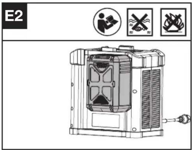
Litij-ionska baterija je zaštićena od dubokog pražnjenja. Kada je baterija prazna, stroj se isključuje pomoću zaštitnog sklopa. Svaka baterija mora biti potpuno napunjena prije prve uporabe.
UKLANJANJE ILI UMETANJE BATERIJE (VIDI SL. F, G)

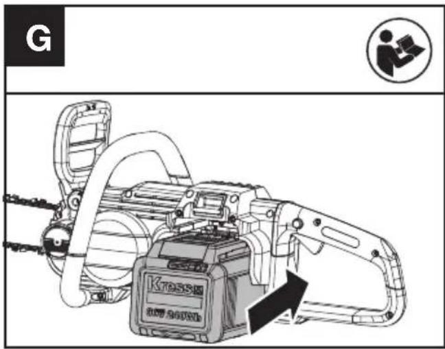
Pritisnite gumb za otpuštanje baterije kako biste baterijski modul izvadili iz alata. Nakon punjenja baterijski modulumetnite u utor za bateriju. Jednostavno guranje i blagi pritisak bit će dovoljni dok se ne začuje klik. Provjerite je li baterija dobro pričvršćena.
NAPOMENA: Kad uklanjate bateriju, držite je čvrsto kako biste izbjegli da vam padne i ošteti se.
UKLJUČIVANJE I ISKLJUČIVANJE (POGLEDAJTE SL. H)

PAŽNJA: Prije korištenja vašeg akumulatorskogg alata provjerite baterijske module. Koristite samo baterijski modul naveden u odjeljku s priborom.
Za uključivanje alata pritisnite gumb za blokadu gasa, zatim do kraja pritisnite okidač gasa i držite ga u tom položaju. Gumb za blokadu gasa sada se može otpustiti. Ako pila ne radi, u nastavku pročitajte informacije o RUČICI KOČNICE LANCA. Za isključivanje otpustite okidač gasa.
NAPOMENA: Kočnica lanca mora se deaktivirati kako bi se pila mogla uključiti.
RUČICA KOČNICE LANCA (vidi sl. I)
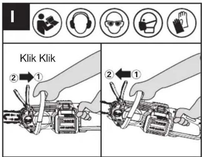
natural_image
Technical line drawing of a mechanical device with chains and gears, no visible text or symbols(1) Umetanje baterijskog kompleta u stroj.
(2) Pazite da dio trupca koji ćete rezati ne leži na tlu. Ako trupac koji režete leži na tlu, nemojte rezati do kraja i dopustiti da lanac dode u kontakt s tlom. Malo zakrenite trupac za konačni rez i odvajanje.
(3) Za držanje pile koristite obje ruke. Uvijek lijevom rukom uhvatite prednju ručku, a desnom stražnju ručku. Koristite čvrsti stisak. Palčevi i prsti moraju se omotati oko ručki pile. (vidi sl. K)
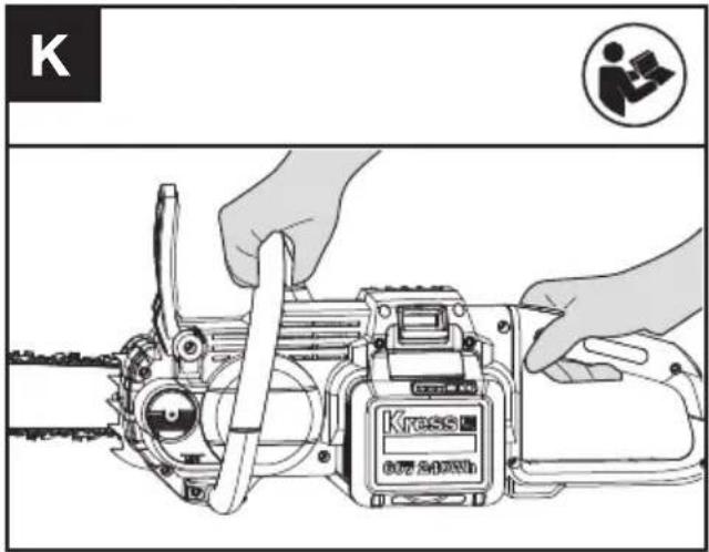
UPOZORENJE: Budite krajnje oprezni prilikom rezanja grana koje su napete. Budite oprezni u pogledu odskakanja drva. Kada se napetost drveta oslobodi, grana
natural_image
Illustration of a hand using a tool to cut a flat surface, with a circular icon labeled 'P' and a gloves symbol (no text or symbols on the diagram itself)a:kut turpijanja; b:položaj turpije.
Kako naoštriti zube
- Pripremite okruglu turpiju za oštrenje rezača. (Vidi sl. R2). Napomena: Čvrsto stegnite vodilicu u škripcu prije oštrenja lanca. Uvjerite se da lanac nije „prikliješten“ i da se može slobodno kretati
po vodilici. Provjerite je li lanac pravilno nategnut. (Vidi odjeljak „Zatezanje lanca“).
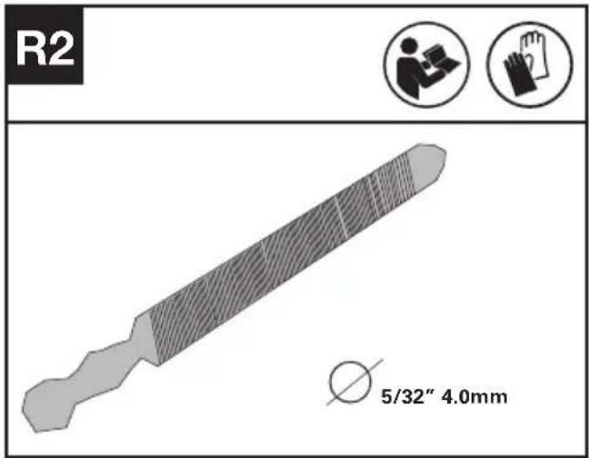
- Naoštrite rezače s pomoću turpije od unutarnje strane reznih zuba prema vanjskoj strani lanca. (Vidi sl. R3).

- Isturpijajte sve rezače s jedne strane vodilice.
- Okrećite lančanu pilu uokolo i isturpijajte sve rezače na suprotnoj strani.
- Pazite da duljina svih reznih zuba bude ista. Kako biste osigurali učinkovito, sigurno i glatko rezanje, isturpijajte visinu mjerača na 0,025" (0,65 mm). Provjerite je li vodeći rub mjerača profila zaobljen. (Vidi sl. R4)
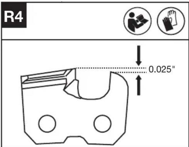
UPOZORENJE
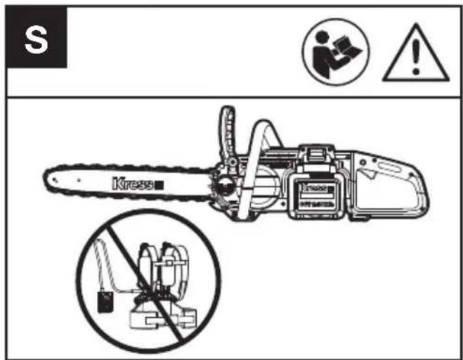
Preporučuje se da radi vaše sigurnosti ne koristite lančanu pilu s kabelskim pojasom za bateriju.
ČIŠĆENJE
- Isključite lančanu pilu i izvadite bateriju.
- Nemojte koristiti agresivne deterdžente ili otapala. Očistite stroj nakon upotrebe vlažnom krpom umočenom u blagi deterdžent.
- Očistite priključak baterije od prljavštine i krhotina, a čistite ga mekom i suhom četkom ili krpom.
- Nemojte prskati vodu na motor i električne komponente.
- Ne koristite visokotlačni perač za čišćenje vašeg stroja.
SKLADIŠTENJE
Complies with the following Directives:
2006/42/EC, 2014/30/EU, 2011/65/
EU&(EU)2015/863, 2000/14/EC amended by 2005/88/EC
18, Dongwang Road, Suzhou Industrial
Park, Jiangsu 215123, P. R. China
INDHOLDSFORTEGNELSE
INTRODUKTION 323
KOMPONENTLISTE 325
ORIGINAL BRUGSANVISNING....326
SAMLING OG BETJENINGS....332
TRANSPORT 338
VEDLIGEHOLDELSE AF SAVEN OG SIKKERHED 338
RENG∅RING 340
OPBEVARING....340
FEJLFINDING....341
TEKNISK DATA....341
KONFORMITETSERKLÆRING 342
INTRODUKTION
Kære kunde,
4. Afgrening
natural_image
Diagram of a mechanical or structural component with directional arrows indicating movement, labeled Fig.2 (no text or symbols on the diagram itself)natural_image
Illustration of a person using a saw to cut a tree stump, with no text or symbols present.SYMBOLER
natural_image
Technical line drawing of a mechanical device with gear and shaft, no visible text or symbolsSÅDAN RENGÕRES SVÆRDETS SKINNER:
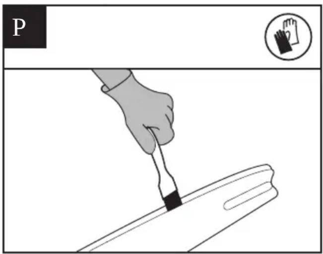
a:Filevinkel; b:filens position.
ADVARSEL
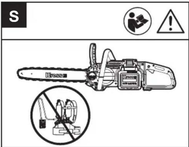
EU&(EU)2015/863, 2000/14/EC amended by 2005/88/EC
Afprøvningsorgan involveret
18, Dongwang Road, Suzhou Industrial
Park, Jiangsu 215123, P. R. China
SISÄLLYSLUETTELO
JOHDANTO....344
KOMPONENTTILISTA ....346
ALKUPERÄISET OHJEET 347
ASENNUS & OPERAATIO....353
KULJETUS....359
SAHAN HUOLTOTOIMENPITEET 359
PUHDISTUS....361
VARASTOINTI....361
VIANMÄÄRITYSTAULUKKO 362
TEKNISET TIEDOT 363
FIN
VAATIMUSTENMUKAISUUSVAKUUTUS 364
JOHDANTO
Hyvä asiakas,

KOMPONENTTILISTA
- KETJU
- OHJAUSTANKO
- KETJUJARRUN VIPU (KÄSISUOJUS)
- ETUKAHVA
- AKKUYKSIKÖN VAPAUTUSPAINIKE
- VAPAUTUSPAINIKE
- TAKAKAHVA
- TAKAKAHVAN SUOJUS
- ON/OFF-VIRTAKYTKIN
- AKKUYKSIKKÖ *
- ÖLJYTASOIKKUNA
- ÖLJYN TÄYTTÖKORKKI
- PUSKURIN PIIKKI
- KONESUOJA
- KUUSIOMUTTERIT
- KETJUN KIRISTYSRUUVI
- KETJUN SUUNTASYMBOLI
- ÖLJYLÄHTÖ
- TANGON KOHDISTUSTAPIT
- TANGON ALUSTA
- KETJUPYÖRÄ
- SUOJAKOTELO
- HYLSYVÄÄNNIN (KATSO KUVA A1)
- KETJUN KIRISTYSTAPPI
- KETJUN KIRISTYSREIKÄ (KATSO KUVA A2)
ALKUPERÄISET OHJEET TURVALLISUUSOHJEET TUOTETURVALLISUUS YLEISET SÄHKÖTYÖKALUJEN TURVALLISUUTEEN LIITTYVÄT VAROITUKSET
4. Puun karsiminen
natural_image
Diagram of a mechanical or structural component with directional arrows indicating flow or movement (no text or symbols)natural_image
Illustration of a person using a tool on a wooden beam with tree stumps in the background (no text or symbols)SYMBOLIT
Note: Fig E1 only applies for the battery pack with battery indicator light.
natural_image
Technical line drawing of a mechanical device with gear and shaft components (no readable text or symbols)natural_image
Illustration of a hand using a tool to cut a piece of paper or paper (no text or symbols present)a:Viilauskulma; b:viilan asento.
WARNING

18, Dongwang Road, Suzhou Industrial
Park, Jiangsu 215123, P. R. China
INNHOLDFORTEGNELSE
INTRODUKSJON....365
KOMPONENTLISTE 367
ORIGINAL DRIFTSINSTRUKS 368
MONTERING OG BRUK 374
TRANSPORT 379
VEDLIKEHOLD AV SAG OG TILBAKESLAGSSIKKERHET....380
RENGJ∅RING....382
OPPBEVARING 383
FEILS∅KING....384
TEKNISKE DATA....385
SAMSVARSERKLÆRING 386
INTRODUKSJON
Kjære kunde,
4. Grenskjæring
natural_image
Diagram of a mechanical or structural component with directional arrows indicating flow or movement (no text or symbols)5. Kapping av trestammen
natural_image
Illustration of a person using a saw to cut a tree stump, with no text or symbols present.SYMBOLER
STRAMMING AV SAGKJEDET (Se figur B, C)
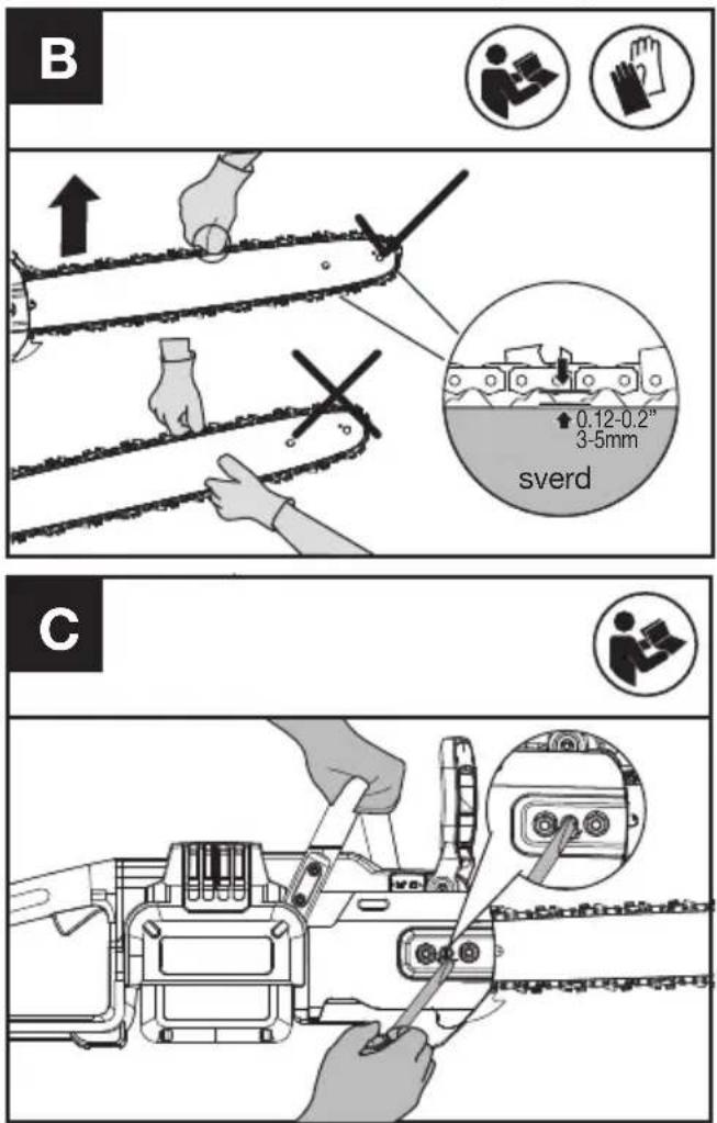
KJEDEBREMS (SE FIGUR I)

natural_image
Technical line drawing of a mechanical device with gears and shaft, no visible text or symbolsVEDLIKEHOLD AV SAG OG TILBAKESLAGSSIKKERHET
FORHOLD SOM KREVER VEDLIKEHOLD AV KJEDE OG SAGSVERD:
ADVARSEL
NOR
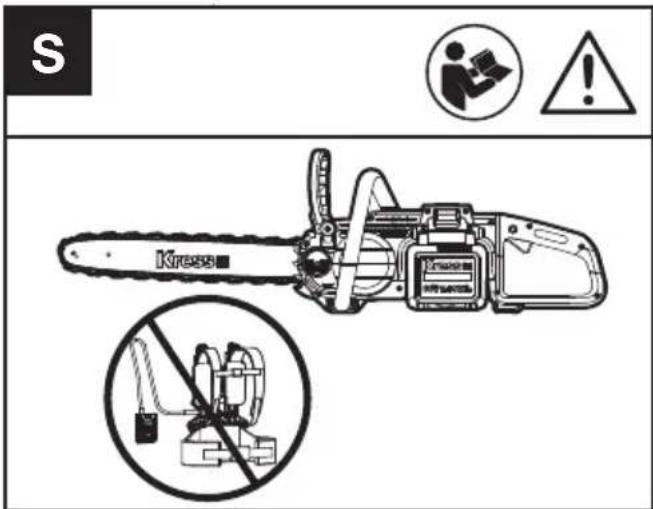
18, Dongwang Road, Suzhou Industrial
Park, Jiangsu 215123, P. R. China
INNEHÅLLSFÖRTECKNING
INTRODUKTION....386
KOMPONENTER....388
SÄKERHET....389
MONTERING & HANTERING....395
TRANSPORT....400
SÅGUNDERHÅLL....401
RENGÖRING....403
FÖRVARING....403
FELSÖKNING....404
TEKNISK INFORMATION......405
DEKLARATION OM ÖVERENSSTÄMMELSE......406
INTRODUKTION
Bästa kund,


KOMPONENTER
- SÅGKEDJA
- SVÄRD
- HANDTAG KEDJEBROMS (HANDSKYDD)
- FRÄMRE HANDTAG
- BATTERIPAKETETS LÅSNING
- LÅSKNAPP
- BAKRE HANDTAG
- BAKRE HANDVAKTEN
- STRÖMSTÄLLARE TILL/FRÅN
- BATTERIPAKET *
- OIJENIVÄFÖNSTER
- OLJETANKLOCK
- STABILISERINGSTAGGAR
- MOTORKÅPA
- SEXKANTSMUTTRAR
- KEDJESPÄNNINGSSKRUV
- KEDJERIKTNINGSSYMBOL
- OIJEMUNSTYCKE
- SVÄRDETS LOKALISERADE BULTAR
- KLÄMMA
- KEDJEHJUL
- SKYDDANDE SKIDA
- SKRUVNYCKEL (SE BILD A1)
- KEDJESPÄNNINGSSTIFT
- KEJDESPÄNNINGSHÅL (SE BILD A2)
SÄKERHETSFÖRESKRIFTER SÄKERHETSVARNINGAR GENERELLA SÄKERHETS- VARNINGAR FÖR ELVERK- TYG

4. Kvistning
natural_image
Diagram of a mechanical or structural component with directional arrows indicating movement, labeled Fig.2 (no text or symbols on the diagram itself)natural_image
Illustration of a person cutting wood with a saw, surrounded by tree stumps (no text or symbols)SYMBOLER
natural_image
Technical line drawing of a mechanical device with gear and shaft components (no text or symbols)a:Filvinkel; b:filposition.
Hur skären vässas
WARNING
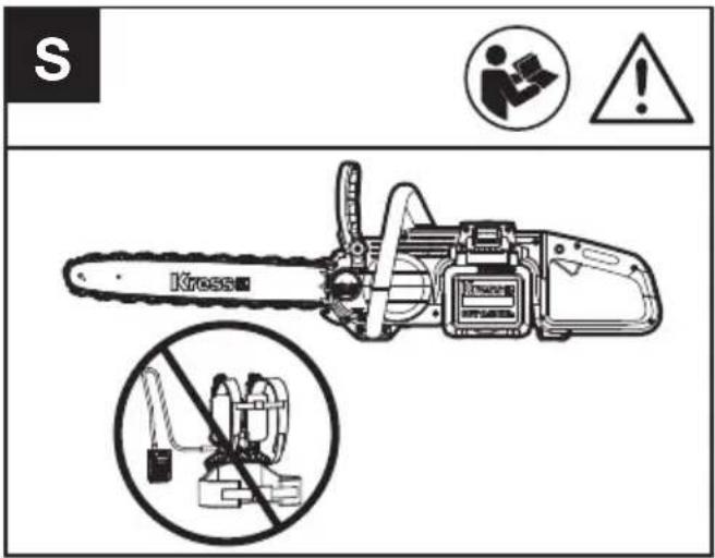
EU&(EU)2015/863, 2000/14/EC amended by
2005/88/EC
Berört notifierat organ:
Namn: Intertek Deutschland GmbH (Berört notifierat organ 0905)
18, Dongwang Road, Suzhou Industrial
Park, Jiangsu 215123, P. R. China

Copyright © 2023, Positec. All Rights Reserved.
AR01693502