KC330.9 - Saw KRESS - Free user manual and instructions
Find the device manual for free KC330.9 KRESS in PDF.

| Product type | Cordless pole saw |
| Brand | Kress |
| Model | KC330.9 |
| Machine weight | 5.7 kg |
| Power supply | Li-Ion battery 60 V max (54 V nominal) |
| Recommended battery | KAC804, 4 Ah |
| Recommended charger | KAC840, 30 A |
| Guide bar length | 25 cm (10") |
| Chain pitch | 3/8" LP |
| Chain gauge | 1.1 mm |
| Cutting speed | High: 17 m/s, Low: 13 m/s |
| Oil tank capacity | 160 ml |
| Sound pressure level (LpA) | 88 dB(A) |
| Sound power level (LwA) | 100.75 dB(A) |
| Vibration (ah) | 3.2 m/s² |
| Intended use | Pruning and trimming branches out of reach |
| Safety devices | Throttle trigger, safety deactivation lever, anti-kickback protection |
| Maintenance | Chain tension, sharpening, rail cleaning, regular lubrication |
| Protection rating | IPX4 |
| Warranty | Consult manual or dealer |
Frequently Asked Questions - KC330.9 KRESS
User questions about KC330.9 KRESS
0 question about this device. Answer the ones you know or ask your own.
Ask a new question about this device
Download the instructions for your Saw in PDF format for free! Find your manual KC330.9 - KRESS and take your electronic device back in hand. On this page are published all the documents necessary for the use of your device. KC330.9 by KRESS.
USER MANUAL KC330.9 KRESS
natural_image
Pure mechanical lever diagram without any text, numbers, or symbols| 60V 25 cm Pole Saw | EN | P03 |
| 60V 25 cm Teleskopstangensäge | D | P24 |
| Élagueuse sur perche 60V 25 cm | F | P46 |
| Motosega a pertica da 60V 25 cm | I | P68 |
| Motosierra de pértiga de 60V y 25 cm | ES | P90 |
| Serra com haste telescópica de 25 cm e 60 V | PT | P112 |
| 60 V 25 cm stokzaag | NL | P134 |
| 60V 25 cm Póznafúrész | HU | P156 |
| Fierastrău telescopic cu accumulator de 60V și 25 cm | RO | P178 |
| Pilarka na wysięgniku 60 V 25 cm | PL | P201 |
| Teleskopická pila s baterii 60V 25 cm | CZ | P223 |
| 60 V 25 cm dlhá tyčová píla | SK | P245 |
| Žaga na palici 60 V 25 cm | SL | P267 |
| Štapna pila od 60 V i 25 cm | HR | P289 |
| 60 V 25 cm stangsav | DK | P310 |
| 60 V 25 cm Oksasaha | FIN | P330 |
| 60V 25 cm stangsag | NOR | P350 |
| 60V 25 cm Teleskopstångsåg | SV | P370 |
KC330 KC330.X
TABLE OF CONTENTS
INTRODUCTION....3
COMPONENT LIST....5
PRODUCT SAFETY....6
ASSEMBLY & OPERATION....9
TRANSPORTATION 16
SAW MAINTENANCE ....17
CLEANNING....19
STORAGE....19
TROUBLESHOOTING 20
TECHNICAL DATA 21
DECLARATION OF CONFORMITY 22
INTRODUCTION
Dear Customer,
Thank you for buying this Kress Commercial product. We are dedicated to developing high quality products to meet your commercial landscaping requirements.
The Kress brand is synonymous with premium quality service. Over the years of your product's life, if you have any questions or concerns about your product, please contact your dealer or our Customer Service Team for assistance.
We are confident you will enjoy working with your Kress product for years to come.
INTENDED USE
This pole saw is designed for pruning and trimming branches beyond arms reach. All cuts should be across the grain. This product is intended for cutting wood only.
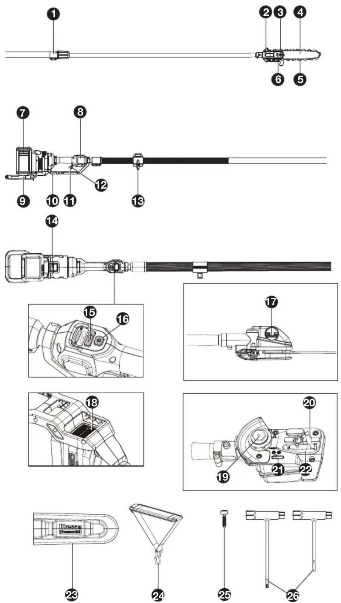
COMPONENT LIST
-
POLE EXTENSION CLAMP RING
-
DRIVE COVER
-
HEX NUT
-
GUIDE BAR
-
CHAIN
-
CHAIN TENSIONING SCREW
-
BATTERY PACK*
-
DISPLAY
-
REAR HANDLE ASSEMBLY
-
THROTTLE GUARD
-
THROTTLE TRIGGER
* Not all the accessories illustrated or described are included in standard delivery.
ORIGINAL INSTRUCTION PRODUCT SAFETY GENERAL POWER TOOL SAFETY WARNINGS
WARNING Read all safety warnings, instructions, illustrations and specifications provided with this power tool. Failure to follow all instructions listed below may result in electric shock, fire and/or serious injury.
Save all warnings and instructions for future reference.
The term “power tool” in the warnings refers to your mains-operated (corded) power tool or battery-operated (cordless) power tool.
1. WORK AREA SAFETY
a) Keep work area clean and well lit. Cluttered or dark areas invite accidents.
b) Do not operate power tools in explosive atmospheres, such as in the presence of flammable liquids, gases or dust. Power tools create sparks which may ignite the dust or fumes.
c) Keep children and bystanders away while operating a power tool. Distractions can cause you to lose control.
2. ELECTRICAL SAFETY
a) Power tool plugs must match the outlet. Never modify the plug in any way. Do not use any adapter plugs with earthed (grounded) power tools. Unmodified plugs and matching outlets will reduce risk of electric shock.
b) Avoid body contact with earthed or grounded surfaces, such as pipes, radiators, ranges and refrigerators. There is an increased risk of electric shock if your body is earthed or grounded.
c) Do not operate the machine in rain or wet conditions. This may increase the risk of electric shock. Once got wet in the rain during operation, the machine and the battery should be dried before storing or charging. Remove the battery and reinsert it if the machine fails to turn on. Keep battery connection free of dirt and debris, and clean with a soft and dry brush or cloth.
d) Do not abuse the cord. Never use the cord for carrying, pulling or unplugging the power tool. Keep cord away from heat, oil, sharp edges or moving parts. Damaged or entangled cords increase the risk of electric shock.
e) When operating a power tool outdoors, use an extension cord suitable for outdoor use. Use of a cord suitable for outdoor use reduces the risk of electric shock.
f) If operating a power tool in a damp location is unavoidable, use a residual current device (RCD) protected supply. Use of an RCD reduces the risk of electric shock.
3. PERSONAL SAFETY
a) Stay alert, watch what you are doing and use common sense when operating a power tool. Do not use a power tool while you are tired or under the influence of drugs, alcohol or medication. A moment of inattention while operating power tools may result in serious personal injury.
b) Use personal protective equipment. Always wear eye protection. Protective equipment such as dust mask, non-skid safety shoes, hard hat, or hearing protection used for appropriate conditions will reduce personal injuries.
c) Prevent unintentional starting. Ensure the switch is in the off-position before connecting to power source and/or battery pack, picking up or carrying the tool. Carrying power tools with your finger on the switch or energising power tools that have the switch on invites accidents.
d) Remove any adjusting key or wrench before turning the power tool on. A wrench or a key left attached to a rotating part of the power tool may result in personal injury.
e) Do not overreach. Keep proper footing and balance at all times. This enables better control of the power tool in unexpected situations.
f) Dress properly. Do not wear loose clothing or jewellery. Keep your hair, clothing and gloves away from moving parts. Loose clothes, jewellery or long hair can be caught in moving parts.
g) If devices are provided for the connection of dust extraction and collection facilities, ensure these are connected and properly used. Use of dust collection can reduce dust-related hazards.
h) Do not let familiarity gained from frequent use of tools allow you to become complacent and ignore tool safety principles. A careless action can cause severe injury within a fraction of a second.
4. POWER TOOL USE AND CARE
a) Do not force the power tool. Use the correct power tool for your application. The correct power tool will do the job better and safer at the rate for which it was designed.
b) Do not use the power tool if the switch does not turn it on and off. Any power tool that cannot be controlled with the switch is dangerous and must be repaired.
c) Disconnect the plug from the power source and/or the battery pack from the power tool before making any adjustments, changing accessories, or storing power tools. Such preventive safety measures reduce the risk of starting the power tool accidentally.
d) Store idle power tools out of the reach of children and do not allow persons unfamiliar with the power tool or these instructions to operate the power tool. Power tools are dangerous in the hands of untrained users.
e) Maintain power tools. Check for misalignment or binding of moving parts, breakage of parts
and any other condition that may affect the power tool's operation. If damaged, have the power tool repaired before use. Many accidents are caused by poorly maintained power tools.
f) Keep cutting tools sharp and clean. Properly maintained cutting tools with sharp cutting edges are less likely to bind and are easier to control.
g) Use the power tool, accessories and tool bits etc. in accordance with these instructions, taking into account the working conditions and the work to be performed. Use of the power tool for operations different from those intended could result in a hazardous situation.
h) Keep handles and grasping surfaces dry, clean and free from oil and grease. Slippery handles and grasping surfaces do not allow for safe handling and control of the tool in unexpected situations.
5. BATTERY TOOL USE AND CARE
a) Recharge only with the charger specified by the manufacturer. A charger that is suitable for one type of battery pack may create a risk of fire when used with another battery pack.
b) Use power tools only with specifically designated battery packs. Use of any other battery packs may create a risk of injury and fire.
c) When battery pack is not in use, keep it away from other metal objects, like paper clips, coins, keys, nails, screws or other small metal objects, that can make a connection from one terminal to another. Shorting the battery terminals together may cause burns or a fire.
d) Under abusive conditions, liquid may be ejected from the battery; avoid contact. If contact accidentally occurs, flush with water. If liquid contacts eyes, additionally seek medical help. Liquid ejected from the battery may cause irritation or burns.
e) Do not use a battery pack or tool that is damaged or modified. Damaged or modified batteries may exhibit unpredictable behaviour resulting in fire, explosion or risk of injury.
f) Do not expose a battery pack or tool to fire or excessive temperature. Exposure to fire or temperature above 130 °C may cause explosion.
g) Follow all charging instructions and do not charge the battery pack or tool outside the temperature range specified in the instructions. Charging improperly or at temperatures outside the specified range may damage the battery and increase the risk of fire.
6. SERVICE
a) Have your power tool serviced by a qualified repair person using only identical replacement parts. This will ensure that the safety of the power tool is maintained.
b) Never service damaged battery packs. Service of battery packs should only be performed by the manufacturer or authorized service providers.
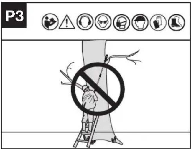
POLE SAW SAFETY WARNINGS
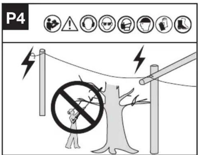
- Keep the pole saw a sufficient distance away from overhead electrical power lines.
- Be aware of the dangerous of operating positions, as well as the risk of being struck by falling branches or branches that, having hit the ground, rebound, the operator may be struck by falling branches or by those that rebound after hitting the ground. Remove the branches in sections.
- Keep bystanders at a safe distance from the machine during its operation.
- Keep firm footing and balance during operation, including the need to use the harness provided.
- Use PPE when operating, including hearing protection, eye protection (visor or glasses) and head protection and clothing.
SAFETY WARNINGS FOR BATTERY PACK
a) Do not dismantle, open or shred cells or battery pack.
b) Do not short-circuit a battery pack. Do not store battery packs haphazardly in a box or drawer where they may short-circuit each other or be short-circuited by conductive materials. When battery pack is not in use, keep it away from other metal objects, like paper clips, coins, keys, nails, screws or other small metal objects, that can make a connection from one terminal to another. Shorting the battery terminals together may cause burns or a fire.
c) Do not expose battery pack to heat or fire. Avoid storage in direct sunlight.
d) Do not subject battery pack to mechanical shock.
e) In the event of battery leaking, do not allow the liquid to come into contact with the skin or eyes. If contact has been made, wash the affected area with copious amounts of water and seek medical advice.
f) Keep battery pack clean and dry.
g) Wipe the battery pack terminals with a clean dry cloth if they become dirty.
h) Battery pack needs to be charged before use. Always refer to this instruction and use the correct charging procedure.
i) Do not maintain battery pack on charge when not in use.
j) After extended periods of storage, it may be necessary to charge and discharge the battery pack several times to obtain maximum performance.
k) Recharge only with the charger specified by Kress. Do not use any charger other than that specifically provided for use with the equipment.
I) Do not use any battery pack which is not designed for use with the equipment.
m) Keep battery pack out of the reach of children.
n) Retain the original product literature for future reference.
o) Remove the battery from the equipment when not in use.
p) Dispose of properly.
q) Do not use battery packs of different manufacture, size or type.
r) Keep the battery away from microwaves and high pressure.
s) Warning! Do not use non-rechargeable batteries.
User manual requirements for wireless product
a) Operation of this device is subject to the following two conditions:
(1) This device may not cause harmful interference, and
(2) this device must accept any interference received, including interference that may cause undesired operation.
b) Caution: Changes or modifications to this unit not expressly approved by the party responsible for compliance could void the user's authority to operate the equipment.
c) NOTE: This equipment generates, uses and can radiate radio frequency energy and, if not installed and used in accordance with the instructions, may cause harmful interference to radio communications. However, there is no guarantee that interference will not occur in a particular installation. If this equipment does cause harmful interference to radio or television reception, which can be determined by turning the equipment off and on, the user is encouraged to try to correct the interference by one or more of the following measures:
-Reorient or relocate the receiving antenna.
-Increase the separation between the equipment and receiver.
-Connect the equipment into an outlet on a circuit different from that to which the receiver is connected.
-Consult the dealer or an experienced radio/TV technician for help.
SAVE THESE INSTRUCTIONS
SYMBOLS
 | To reduce the risk of injury, user must read instruction manual |
 | WARNING |
 | Wear ear protection |
 | Wear eye protection |
 | Wear dust mask |
 | Wear head protection |
 | Protective gloves |
 | Protective footwear |
 | Keep sufficient distance away from electrical power lines |
 | Li-Ion battery. This product has been marked with a symbol relating to ‘separate collection’ for all battery packs and battery pack. It will then be recycled or dismantled in order to reduce the impact on the environment. Battery packs can be hazardous for the environment and for human health since they contain hazardous substances. |
 | |
 | Do not burn |
  | Batteries may enter water cycle if disposed improperly, which can be hazardous for ecosystem. Do not dispose of waste batteries as unsorted municipal waste.Waste electrical products must not be disposed of with household waste. Please recycle where facilities exist. Check with your local authorities or retailer for recycling advice. |
| Environmentally friendly disposal Old electrical appliances must not be disposed of together with the residual waste, but have to be disposed of separately. The disposal at the communal collecting point via private persons is for free. The owner of old appliances is responsible to bring the appliances to these collecting points or to similar collection points. With this little personal effort, you contribute to recycle valuable raw materials and the treatment of toxic substances. | |
 | Unlock |
 | Lock |
NOTE: Before using the tool, read the instruction book carefully.
ASSEMBLY

WARNING! Do not install the battery pack before it has been completely assembled.
Always use gloves when handling the chain.
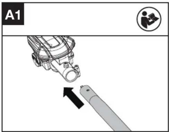
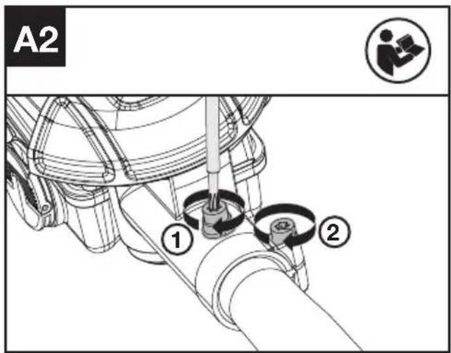
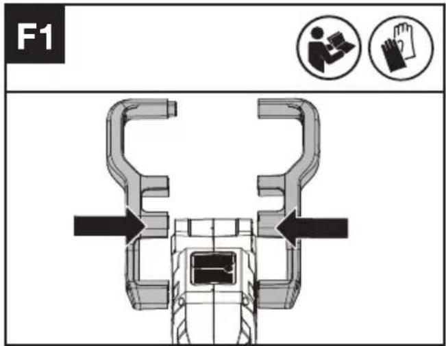
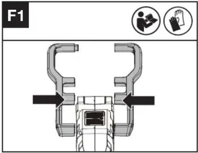
CUTTING HEAD ASSEMBLY (SEE FIG. A1, A2)
Unpack all parts carefully. Place the saw on a solid, level surface. Assemble the cutting head with the pole.
NOTE: Keep the cutting head and machine body in a horizontal position. Make sure the screw is aligned with the hole on the shaft.
CHAIN AND GUIDE BAR ASSEMBLY
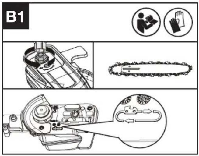
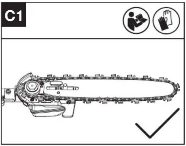
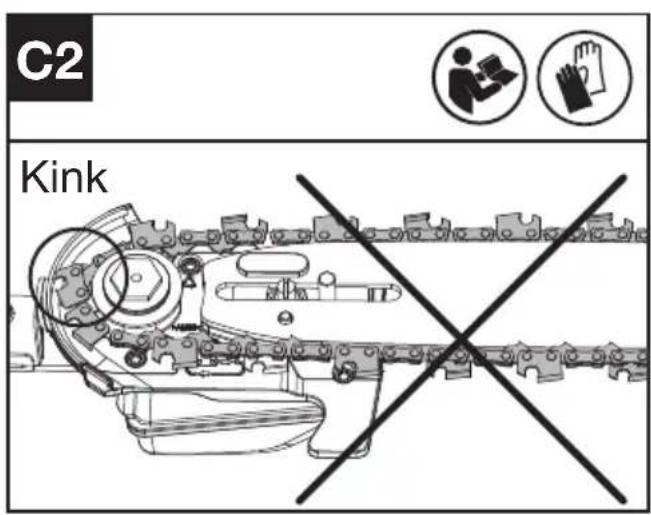
- Loosen the hex nut to remove the drive cover. Slide the chain in the slot around the guide bar. Ensure the chain is in correct running direction. (See Fig. B1)
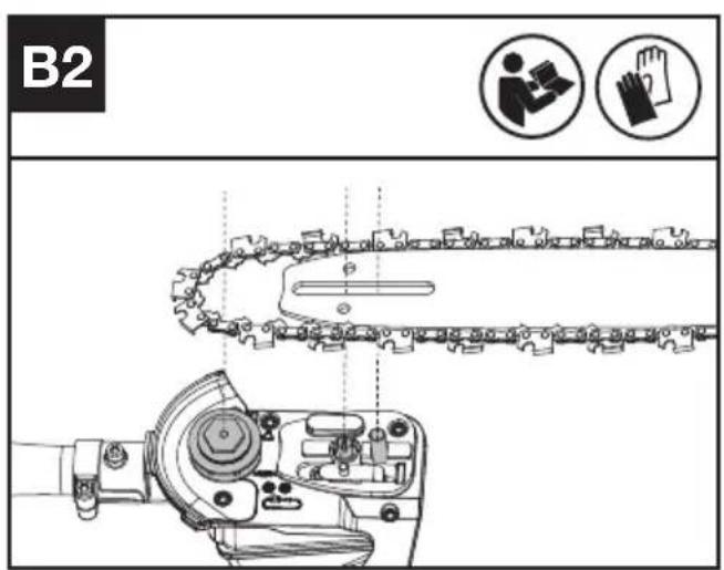
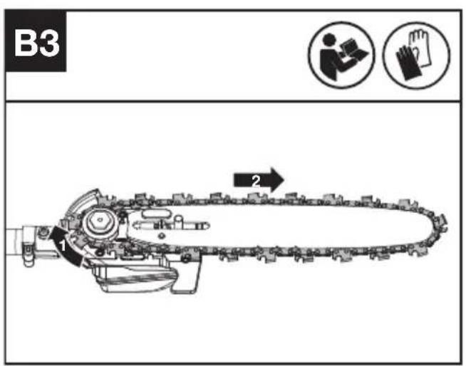
- Fit the chain onto the drive sprocket, so that the bar locating stud on the bar pad fits into the keyway of the opening on the guide bar.(See Fig. B2, B3)
- Assure all parts are seated properly. Make sure the drive links are fully seated in the drive sprocket (See Fig. C1), avoiding a kink as shown in Fig. C2. If kink occurs, pick up on the chain at the guide bar just ahead of the kink and then pull the kink out.
NOTE: Chain should rotate freely but requires a level of force to rotate the chain - Fit the drive cover and tighten the hex nut.
WARNING: The chain is not yet tensioned. Tensioning the chain applies as described under "TENSIONING CHAIN". The chain now needs to be inspected to make sure it is properly tensioned.
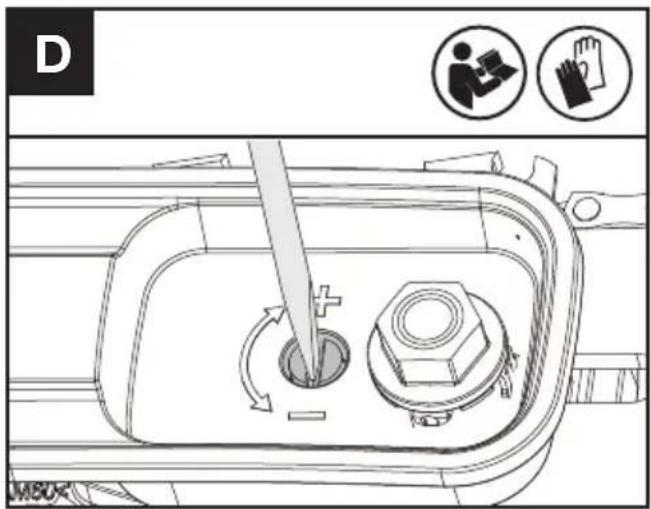
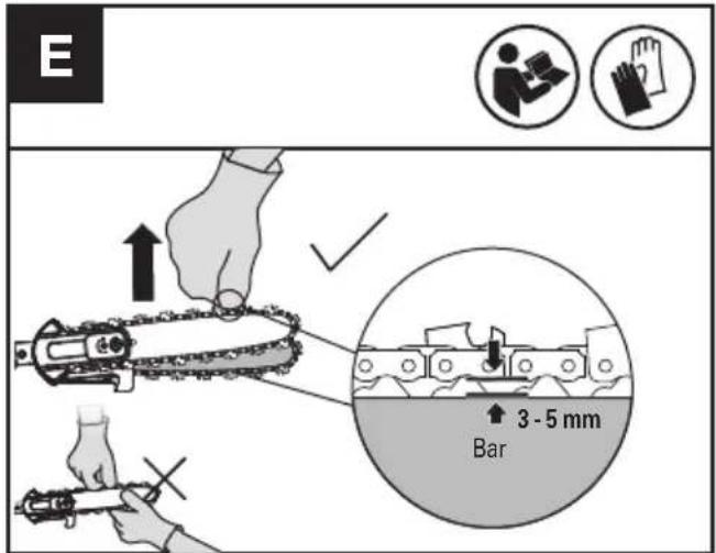
TENSIONING CHAIN (SEE FIG. D, E)
NOTE: New saw chains will seat to the bar when first used. Check the chain tension frequently when first used and tighten when the chain becomes loose around the guide bar.
- Removing the battery pack before adjusting saw chain tension.
- Cutting edges on chain are sharp. Use protective gloves when handling chain.
-
Maintain proper chain tension always. A loose chain may jump out of guide bar groove. This may injure operator and damage chain. A loose chain will cause the chain, bar, and sprocket to wear rapidly.
-
Place the pole saw on any suitable flat surface and loosen the hex nut.
- Turn the chain tensioning screw clockwise until it is tight. (See Fig. D)
NOTE: The tension is automatically increased while the chain tensioning screw is being turned in a clockwise direction. Then tighten the hex nut securely. - Check the tension set by the chain tensioning
screw. The correct chain tension is reached when the chain can be raised approx. Half the drivelink depth from the guide bar in the center. This should be done by using a gloved hand to raise the chain against the weight of the machine. (See Fig. E) Then fully tighten the hex nut.
NOTE: The chain is properly tensioned when it can be lifted off of the guide bar and the drivelink is within the rail of the guide bar.
NOTE: The chain will loosen while cutting and lose proper tension. When the chain becomes loose, loosen the hex nut, retighten the chain tensioning screw then retighten the hex nut to properly reset the chain tension following steps 1 through 3 listed previously.
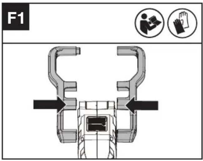
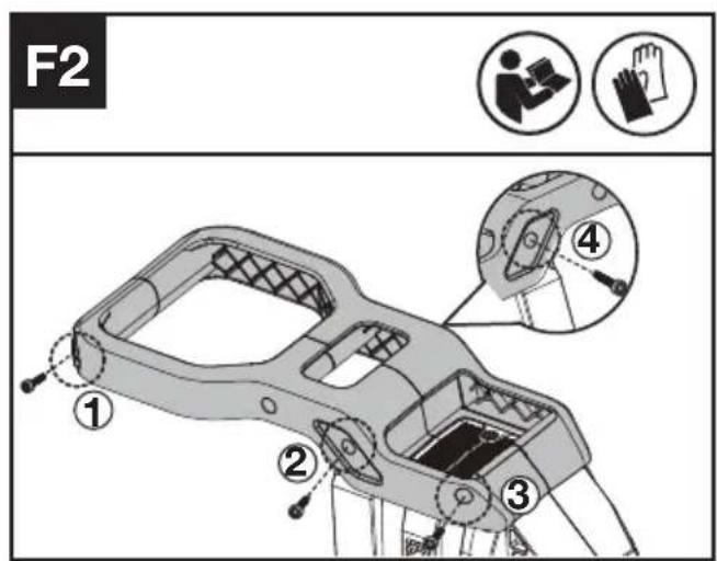
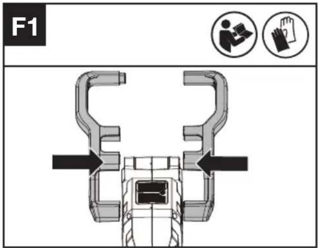
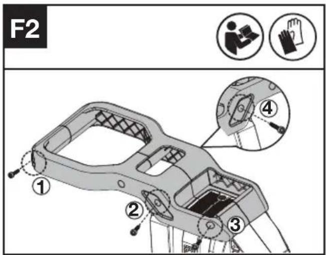
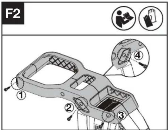
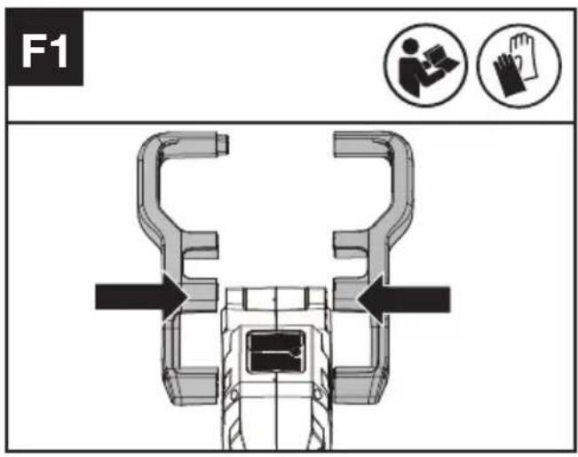
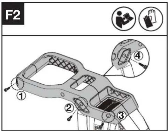
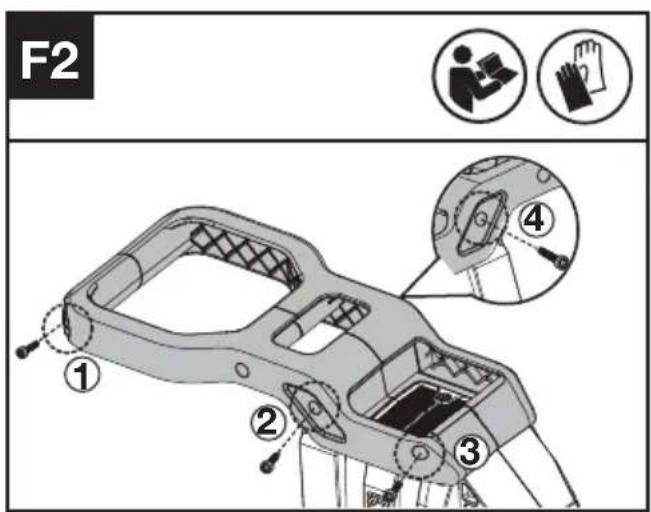
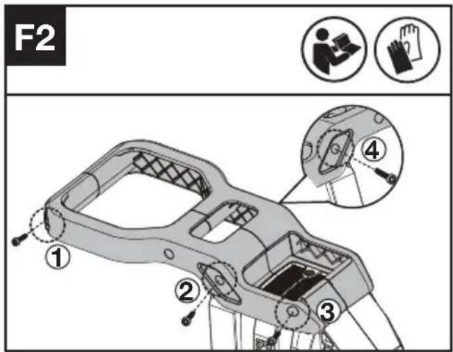
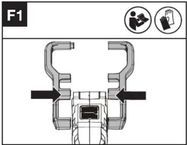
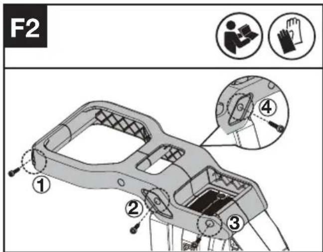
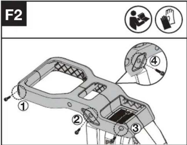
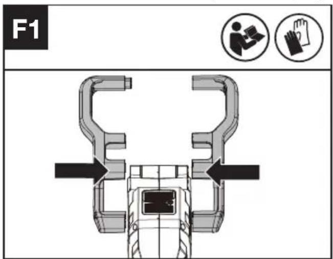
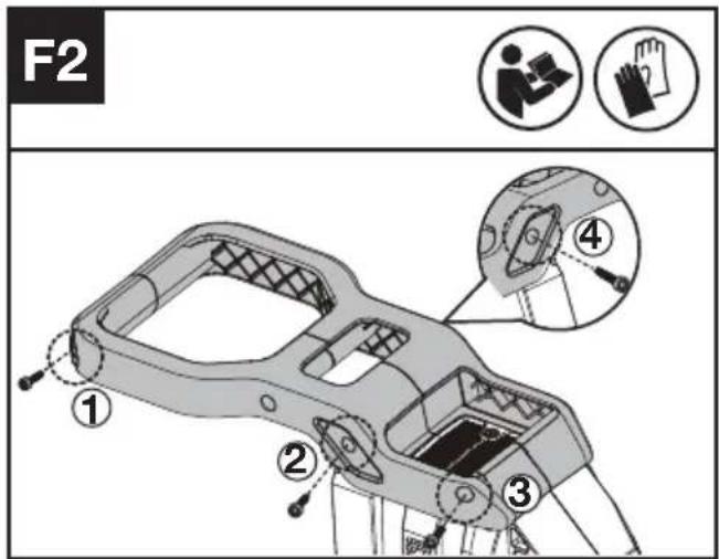
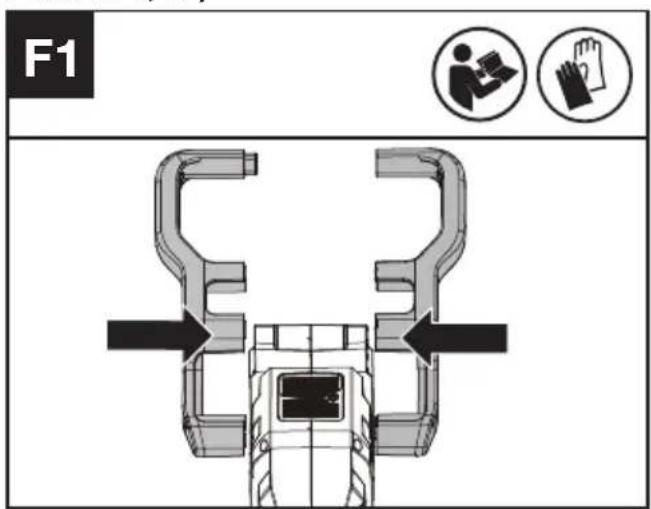
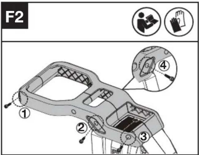
REAR HANDLE ASSEMBLY (SEE FIG. F1, F2)
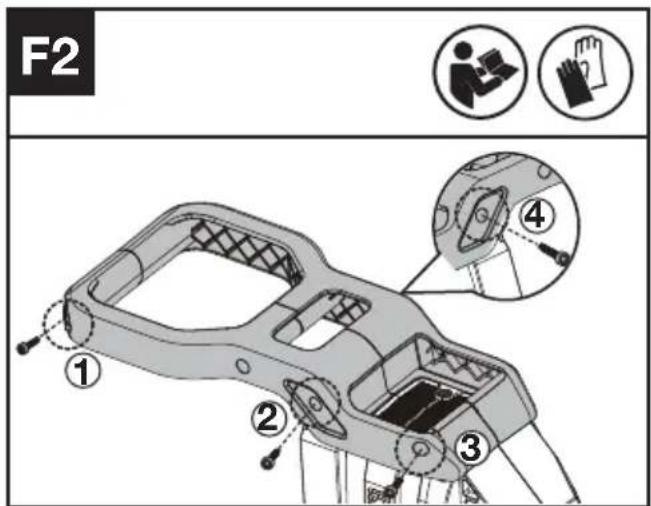
Install the screws in numerical order: 1, 2, 3, and 4 as shown in the figure.
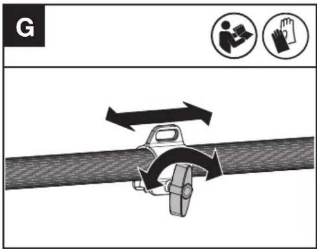
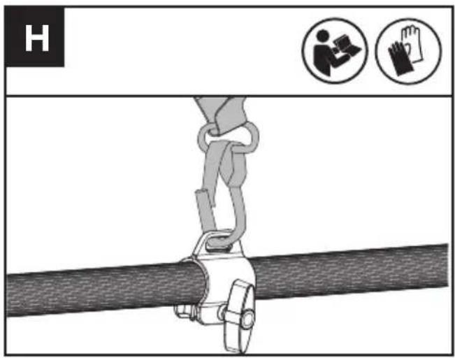
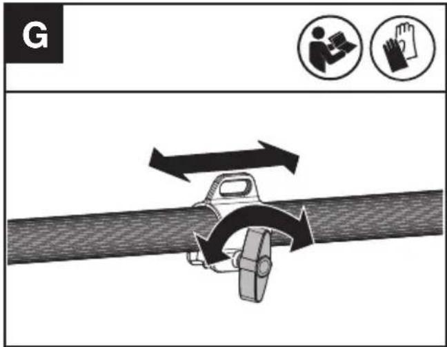
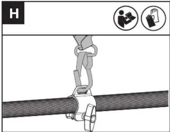
SHOULDER STRAP ASSEMBLY (SEE FIG. G, H)
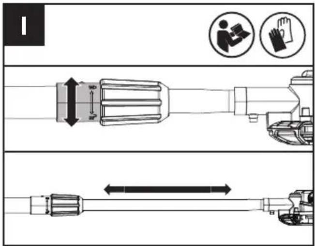
POLE SAW LENGTH ADJUSTMENT (SEE FIG. I)
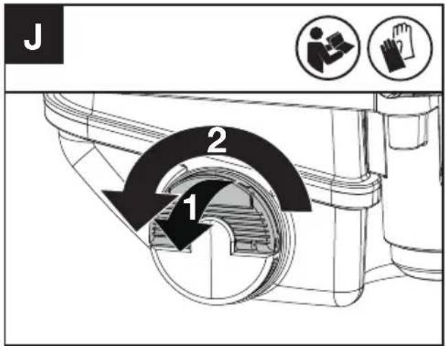
LUBRICATION (SEE FIG. J)

IMPORTANT: The pole saw is not filled with bar & chain oil. It is essential to fill with bar & chain oil before use. Never operate the pole saw without bar & chain oil or allow the tank to become empty, as this will result in extensive damage to the product.
NOTE: Chain life and cutting capacity depend on optimum lubrication. Therefore, the chain is automatically oiled during operation.
FILLING OIL TANK:

WARNING: Remove the battery pack before filling the oil tank.
- Set pole saw on any suitable surface with oil fill cap facing upward.
- Clean area around the oil fill cap with cloth and unscrew the cap by turning it counter clockwise.
- Add bar & chain oil until tank is almost completely full.
- Avoid dirt or debris entering oil tank, refit oil fill cap and tighten by turning clockwise until hand tight.

It is important to use bar and chain lubricant (not automotive oil) that is
formulated to perform over a wide temperature range with no dilution required. This can be found at the location where you purchased this saw or your local hardware store. Do not use dirty, used or otherwise contaminated oils. Damage may occur to the bar or chain. Use of non approved bar & chain oil will void the warranty.
Keep bar oil out of reach of children. If swallowed, call a physician immediately. Store away from heat or open flame.
OPERATION
WARNING! The charger and battery pack are specially designed to work together so do not attempt to use any other devices. Never insert or allow metallic objects into your charger or battery pack connections because of an electrical failure and hazard will occur.
NOTE: Your battery pack is UNCHARGED and you must charge once before use.
The battery charger supplied is matched to the Li-ion battery installed in the machine. Do not use another battery charger.
CHECKING THE BATTERY CHARGE CONDITION (SEE FIG. K)
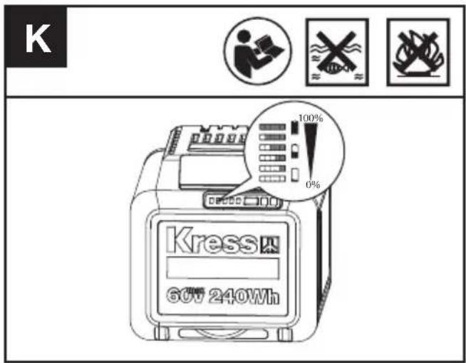
Before starting or after use, press the power test button on the battery pack to check the battery capacity.
NOTE: Fig K only applies for the battery pack with battery indicator light.
| Remarks LED light Battery condition | ||
| Five green lights are illuminated. |  | 80% ≤ Power level ≤ 100% |
| Four green lights are illuminated. | [TOKH] | 60% ≤ Power level < 80% |
| Three green lights are illuminated. |  | 40% ≤ Power level < 60% |
| Two green lights are illuminated. |  | 20% ≤ Power level < 40% |
| One green light is illuminated. |  | 10% ≤ Power level < 20% |
| One green light is flashing. | [T6SY] | 0% ≤ Power level < 10% |
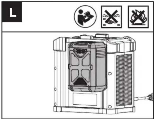
CHARGING YOUR BATTERY PACK (SEE FIG. L)
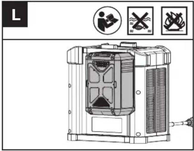
The Li-ion battery is protected against deep discharging. When the battery is depleted, the machine is switched off by means of a protective circuit. Each battery must be fully charged before the first use.
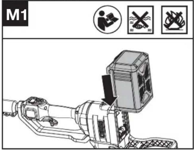
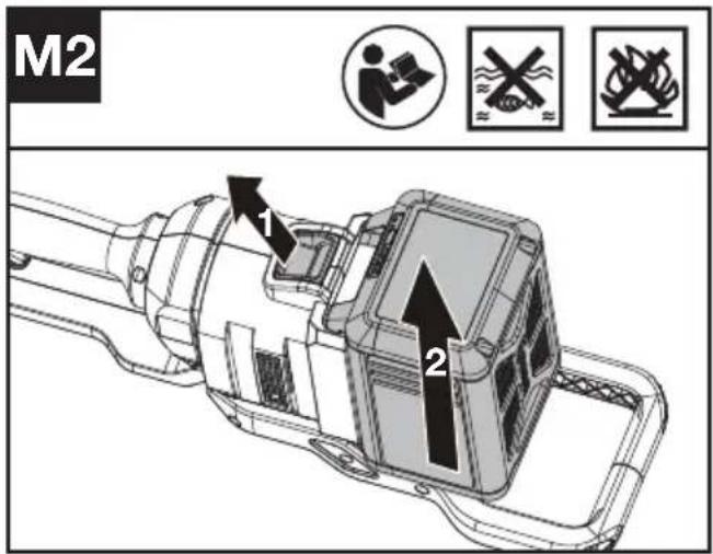
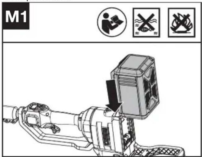
TO REMOVE OR INSTALL BATTERY PACK (SEE FIG. M1, M2)
After recharging, insert the battery pack into the battery port. A simple push and slight pressure will be sufficient until a click is heard. Check to see if the battery is fully secured.
Pull the battery pack release to remove the battery pack from your tool after operation
NOTE: When removing the battery pack, hold it firmly to avoid dropping and injury.
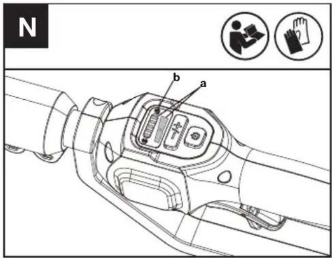
BEFORE OPERATION TESTING THE POLE SAW AND BATTERY (SEE FIG. N)
Checking the controls
- Remove the battery.
- Try to press the throttle trigger. If the throttle trigger can be pressed without pushing the safety lock off lever, the safety lock off lever is defective. Stop using the machine and contact the service agent.
- Push the safety lock off lever first, then press the throttle trigger.
- Release the throttle trigger and the safety lock off lever. If the throttle trigger or the safety lock off lever is stuck and cannot spring back to its original position, stop using the machine and contact the service agent.
Checking the display
- Insert the battery.
- Press the on / off switch.
The product is switched on when the LED (a) is lit.
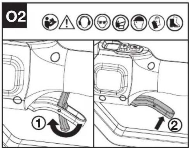
The product is switched off when the LED (a) is out. - Push the safety lock off lever forward first, then squeeze and hold the throttle trigger to start the machine. (See Fig. O2)
- If the warning indicator (b) is flashing, refer to your dealer for solutions.
- Release the throttle trigger. The machine stops after a short delay. If the machine continues to cut, remove the battery and contact the service agent.
SWITCHING ON AND OFF
ATTENTION: Check the battery pack before using your cordless tool. Only use the battery pack listed in the accessories section.
Cutting speed adjustment (See Fig. O1)
- Press the on/off switch.
- Press the minus sign (-) on the speed control to select a lower cutting speed if needed.
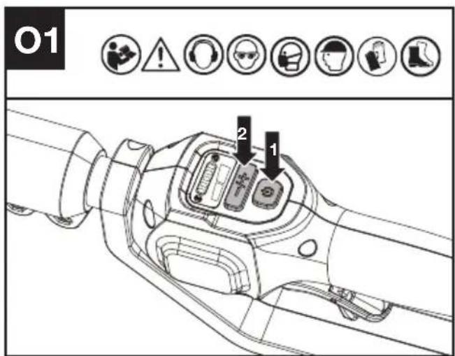
Push the safety lock off lever forward first, then squeeze and hold the throttle trigger to start the machine. (See Fig. O2)
CUTTING
IMPORTANT: Check oil tank periodically. Check chain tension periodically to assure of proper tension.
(1) Installing the battery pack into the machine.
(2) Do not allow the chain to come in contact with ground while operating as this will dull the chain.
(3) Use both hands to grip saw.
(4) Make sure your footing is firm. Keep feet-shoulder width apart. Distribute your weight evenly on both feet.
(5) When ready to make a cut, follow the above starting procedures and speed selection. This will turn saw on. Releasing the trigger will turn the saw off. Make sure the saw is running at full speed before starting a cut.
(6) When starting a cut, slowly place moving chain against the wood. The wood should be as close to the cutting head as possible. Hold saw firmly in place to avoid possible bouncing or skating (sideways movement) of saw.
(7) Guide the saw using light pressure and do not put excessive force on the saw, letting the saw do its work. The motor will overload and can burn out. It will do the job better and safer at the rate for which it was intended.
(8) Remove the saw from a cut with the saw running at full speed. Stop the saw. Make sure the chain has stopped before setting the saw down.
(9) Practice on scrap logs in a secure working area until you are comfortable, using a fluid motion and a steady cutting rate.
KICKBACK SAFETY DEVICES ON THIS SAW
This saw has a low-kickback chain and reduced kickback guide bar. Both items reduce the chance of kickback. However, kickback can still occur with this pole saw.
The following steps will reduce the risk of kickback.
- Use both hands to grip saw while saw is running. Use firm grip.
- Keep all safety items in place on saw. Make sure they work properly.
- Keep solid footing and balance at all times.
- Stand slightly to the left side of saw. This keeps your body from being in direct line with chain.
- Do not let guide bar nose touch anything when chain is moving.
- Do not bury the Guide Bar nose or try plunge cut (boring into wood using guide bar nose).
- Watch for shifting of wood or other forces that may pinch chain.
- Use extreme caution when re-entering a previous cut.
- Use only the low-kickback chain and guide bar that were supplied with this pole saw or recommended.
- Never use a dull or loose chain. Keep chain sharp with proper tension.
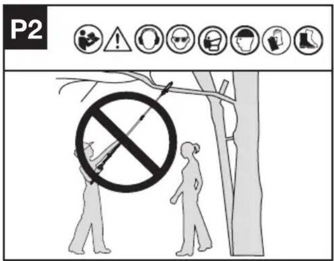
CUTTING HIGH BRANCHES
-
Install the battery pack into the machine.
-
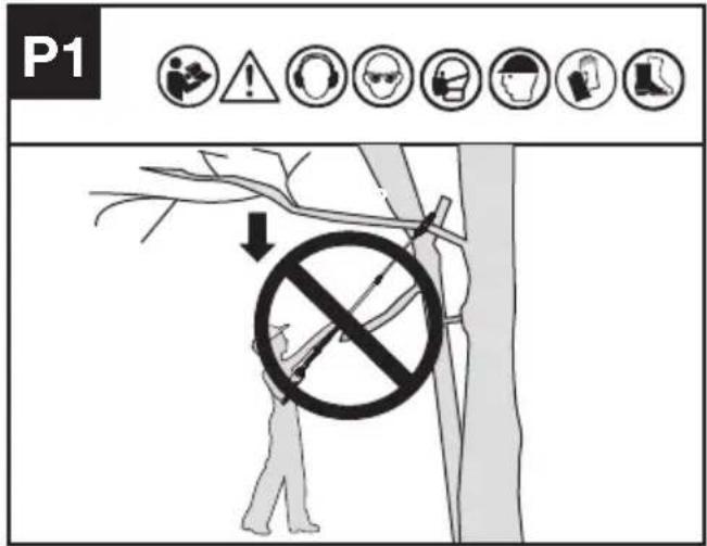
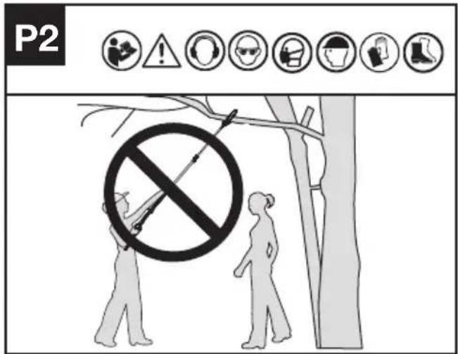
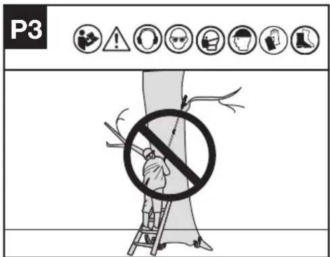
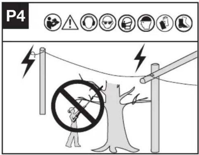
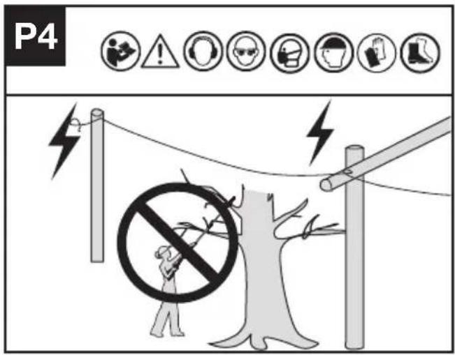
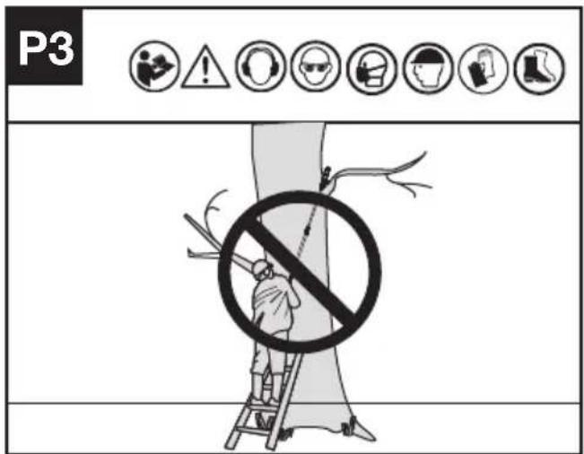
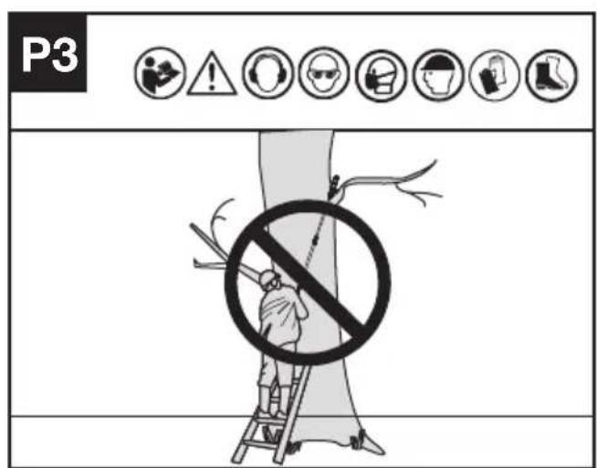
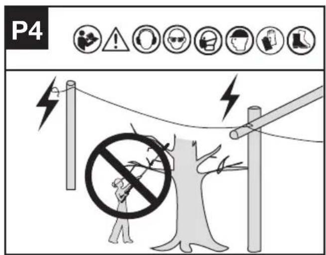
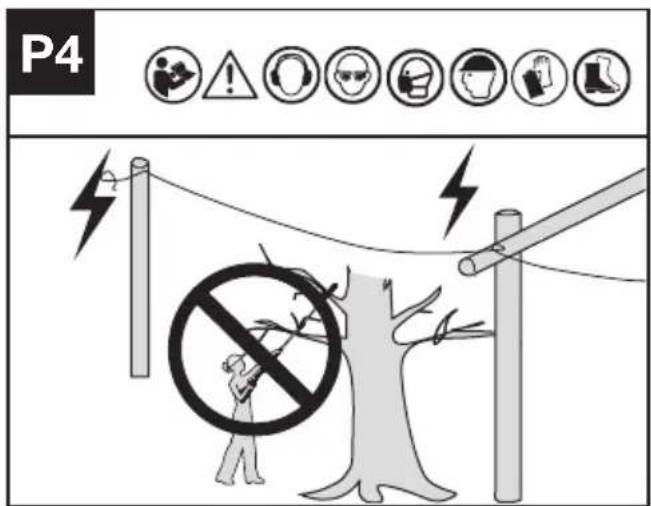
Before cutting a high branch, pay particular attention to the likely path of the falling branch. WARNING: Do not stand directly below a branch being cut. Keep bystanders far away. Do not stand on a ladder or other type of unstable support while using the tool. Do not use the tool near cable, electrical power or telephone lines. Keep 10 ft (3m) away from all power lines. (See Fig. P1-P4)
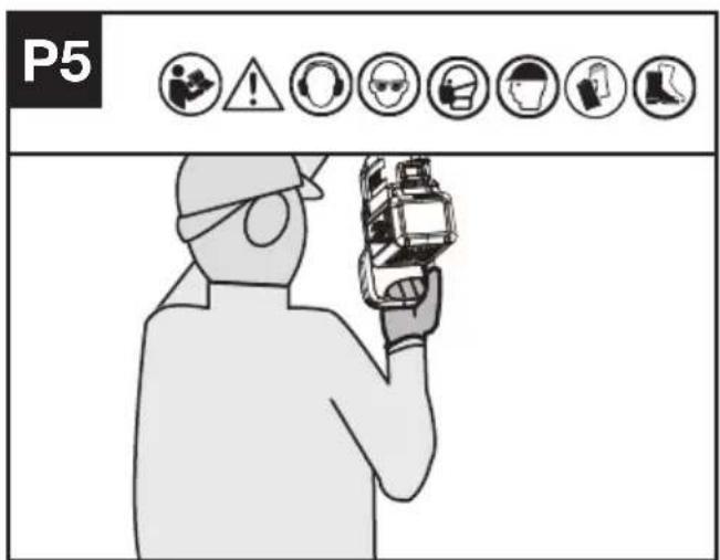
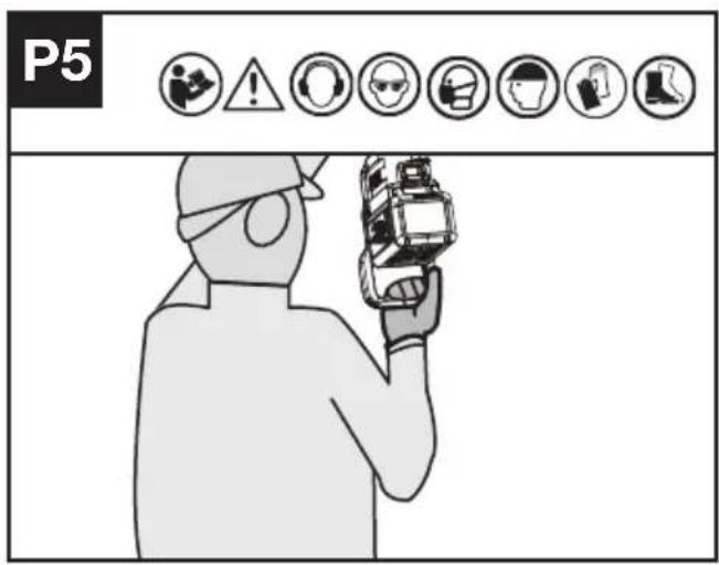
- Use both hands to grip pole saw. Use firm grip. When cutting high or distant objects, hold the rear handle for support. (See Fig. P5).
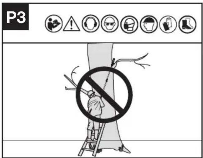
TRIMMING A TREE (PRUNING)
WARNING: Avoid kickback. Kickback can result in severe injury or death.
See Kickback, to avoid risk of kickback.
WARNING: Do not operate pole saw while
- in a tree
• on a ladder or any other unstable surface
• in any awkward position
You may lose control of pole saw causing severe injury.
CAUTION: Seek professional help if facing conditions beyond your ability.
Trimming a tree is the process of cutting limbs from a living tree. Make sure your footing is firm. Keep feet apart. Divide your weight evenly on both feet. Follow directions below to trim a tree.
- Make the first cut a few centimeters (c) from the tree trunk on underside of limb. Use top of guide bar to make this cut. Cut 1/3 through diameter of limb (See Fig. P6).
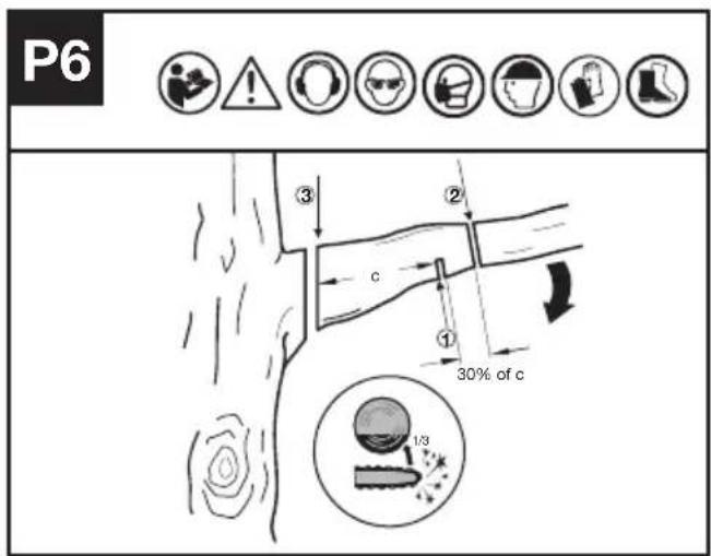
- Move a few centimeters (30% of c) farther up on limb. Make second cut from above limb. Continue cut until you cut limb off.
- Make the third cut as close to the tree trunk as possible fully severing the remaining stub. Use bottom of guide bar to make this cut.
For Battery tools
The recommended ambient temperature range for discharging is -20 °C\~45 °C. The recommended ambient temperature range for the charging system during charging is -5 °C\~45 °C.
Details regarding safe disposal of used batteries At the end of the life of the appliance, remove the battery pack safely before disposing of the appliance. Do not throw batteries away or throw them in the normal trash can. Also do not dispose of the battery with the machine. Remove the used battery pack from the appliance and dispose of it at the nearest or convenient dedicated recycling facility. If in doubt, consult your local environmental protection department. Batteries may enter water cycle if disposed improperly, which can be hazardous for ecosystem. Do not dispose of waste batteries as unsorted municipal waste.
TRANSPORTATION
Transporting the pole saw
- Switch off the pole saw and remove the battery.
- When transporting your pole saw by hand, hold the pole of the pole saw making sure the machine is parallel to the ground and the bar is facing rearward.
- When transporting your pole saw in a vehicle, secure and position it to prevent movement or damage.
Transporting the battery
- Ensure the battery is in a safe condition.
- Use non-conductive packaging when transporting the battery.
- The contained Li-Ion batteries are subject to the dangerous goods legislation requirements.
Transport batteries only when the battery
housing is undamaged. Pack up the batteries in such a manner that cannot move around in the packaging.
SAW MAINTENANCE
Follow the maintenance instructions in this manual. Proper cleaning and maintenance of saw, chain and guide bar can reduce chances of wear. Inspect and maintain saw after each use. This will increase the service life of your saw. If the saw gets wet in the rain during operation, the machine and the battery pack should be dried before storing or charging.
MAINTENANCE AND STORAGE OF POLE SAW
1. Remove the battery pack
- When not in use
• Before moving from one place to another - Before servicing
-
Before changing accessories or attachments, such as saw chain and bar
-
Inspect pole saw before and after each use. Check saw closely if the guard or other part has been damaged. Check for any damage that may affect operator safety or operation of saw. Check for alignment or binding of moving parts. Check for broken or damaged parts. Do not use pole saw if damage affects safety or operation. Have damage repaired by authorized service center.
3. Maintain pole saw with care.
- Keep chain sharp, clean, and lubricated for better and safer performance.
- Follow steps outlined in this manual to sharpen chain.
- Keep handles dry, clean, and free of oil and grease.
-
Keep all screws and nuts tight.
-
When servicing, use only identical replacement parts.
5. When not in use, always store pole saw
- in a high or locked place, out of children's reach
- in a dry place
• with protective scabbard in position
BAR MAINTENANCE
To maximize bar life, the following bar maintenance is recommended.
The bar rails that carry the chain should be cleaned before storing the tool or if the bar or chain appear to be dirty.
The rails should be cleaned every time the chain is removed.
Occasional de-burring of the bar rails may be necessary with a flat file
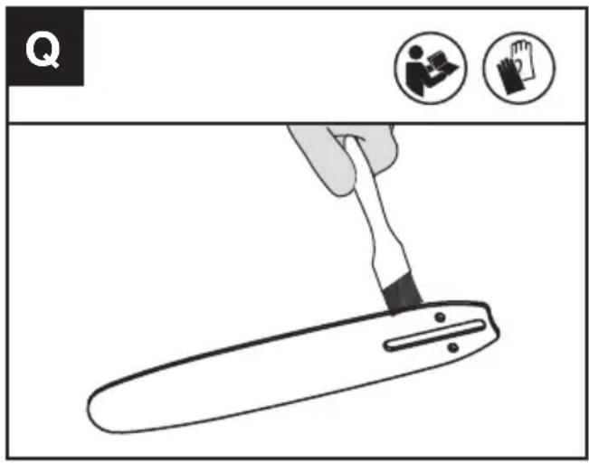
TO CLEAN THE BAR RAILS
- Remove chain cover and bar and chain. (see section ASSEMBLY)
- Using a wire brush, screwdriver or similar tool, clear the residue from the inner groove of the bar. (See Fig. Q)
- Make sure to clean oil passages thoroughly.
CONDITIONS WHICH REQUIRE CHAIN AND GUIDE BAR MAINTENANCE:
- Saw cuts to one side or at an angle.
- Saw has to be forced through the cut.
- Inadequate supply of oil to the bar and chain.
Check the condition of the guide bar each time the chain is sharpened. A worn guide bar will damage the chain and make cutting difficult.
After each use, remove the battery pack, clean all sawdust from the guide bar and sprocket hole.
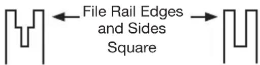
When rail top is uneven, use a flat file to restore square edges by removing any burrs from the side or top of the bar.
Worn Groove Correct Groove
Replace the guide bar when the groove is worn, the guide bar is bent or cracked, or when excess heating or burring of the rails occurs. If replacement is necessary, use only the guide bar specified for your saw in the repair parts list or on the decal located on the pole saw.
REPLACING BAR & CHAIN
Replace chain when cutters are too worn to sharpen or when the chain becomes inoperable. Only use replacement chain noted in this manual.
Inspect guide bar before sharpening chain. A worn or damaged guide bar is unsafe. A worn or damaged guide bar will damage chain. It will also make cutting harder.
SHARPENING SAW CHAIN

WARNING: Remove the battery pack before servicing. Severe injury or death could occur from electrical shock or body contact with moving chain.
Cutting edges on chain are sharp. Use protective gloves when handling chain.
Keep chain sharp. Your saw will cut faster and more safely. A dull chain will cause undue sprocket, guide bar, chain, and motor wear. If you must force chain into wood and cutting creates only fine sawdust with few large chips, chain is dull.
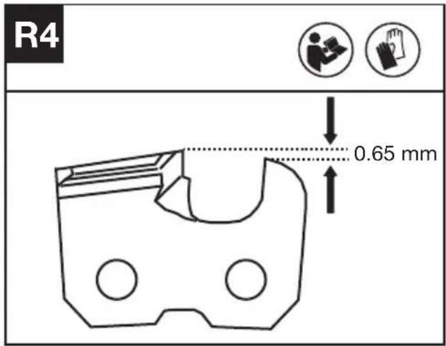
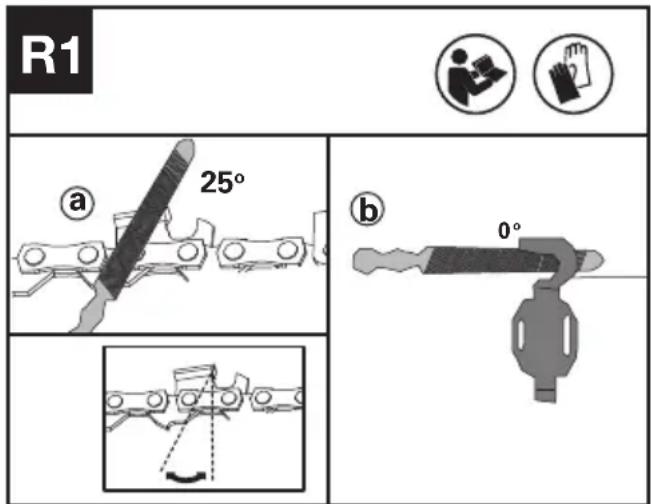
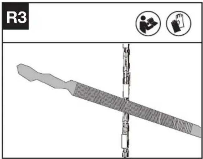
Before sharpening, please pay attention of the following steps:(See Fig R1)
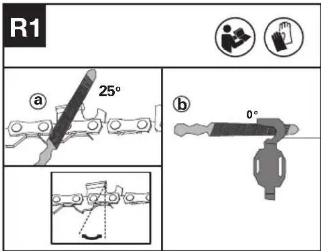
a:Filing angle; b:file position
How to sharpen the cutters
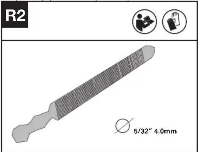
- Prepare a round file to sharpen the cutters.(See Fig R2).Note: Firmly clamp the guide bar in a vice before sharpening the chain. Ensure that the chain is not "nipped" and can freely move on the guide bar. Check that the chain is properley tensioned. (See "Tensioning Chain" section)
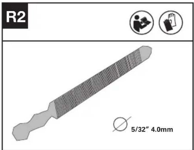
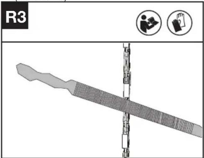
- Sharpen the cutters with file from the inner side of cutting teeth towards the outside of the chain. (See Fig R3)
- File all the cutters on one side of the guide bar.
- Turn the chainsaw around and file all of the cutters on the opposite side.
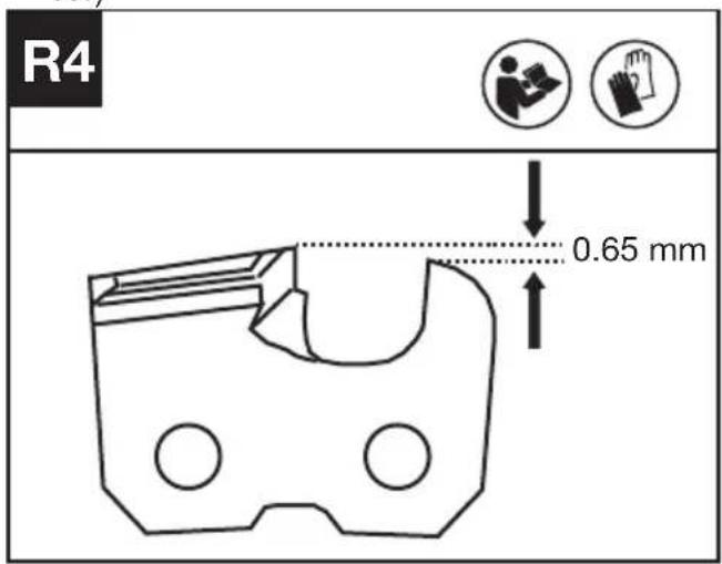
- Ensure that the length of all cutting teeth is same. To ensure efficient, safe and smooth cutting, file the depth gauge height to 0.65mm. Make sure that the leading edge of the depth gauge is rounded off.(See Fig R4)
INSPECKING AND MAINTAINING THE CHAIN SPROCKET

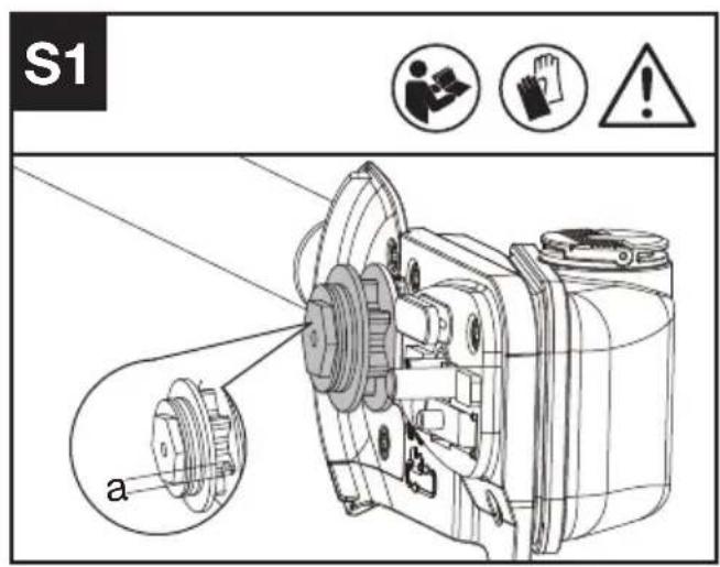
WARNING: Before check, it is a must to turn off the pole saw and remove the battery.
- Remove the dive sprocket cover, saw chain and guide bar.
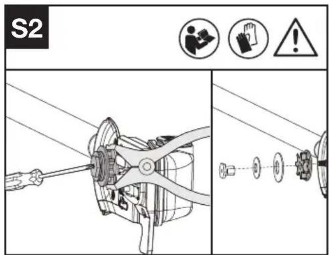
- Check if the wear marks are deeper than a=0.5 mm as shown in Fig. S1, if so, then the chain sprocket should be replaced. (See Fig. S1)
- When replace chain sprocket, control the sprocket with pliers and use screwdriver to lossen nut and replace it. (See Fig. S2)

CLEANING
- Switch off the pole saw and remove the battery.
- Do not use aggressive detergents or solvents. Clean the machine after use with a damp cloth dipped in mild detergent.
- Keep battery connection free of dirt and debris, and clean with a soft and dry brush or cloth.
- Do not spray water onto the motor and electrical components.
- Do not use pressure washer to clean your machine.
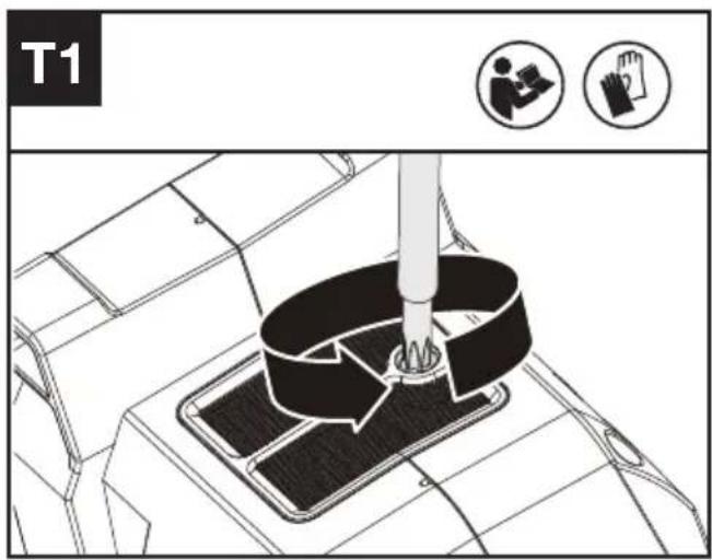
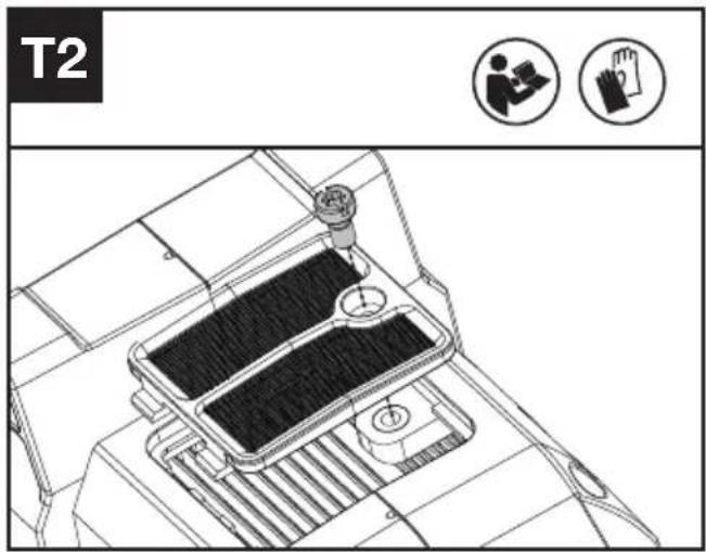
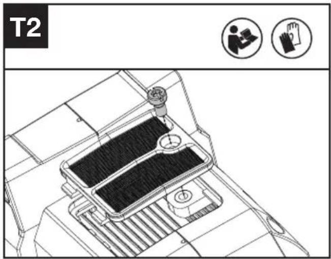
Cleaning the air vents (See Fig. T1, T2)
- Clean the area around the air vents. Use a damp cloth or a soft brush.
- Unscrew and remove the air vents.
- Wash the air vents with running water to remove the dirt.
- Allow the air vents to dry in the air. And then install it in the housing by tightening the screw.
STORAGE
- Remove the battery pack from the pole saw before storage.
- Store the pole saw and the battery in a dry and secure place that is inaccessible to children and other unauthorized people.
- Store the battery only within a temperature range between 5 °C and 25 °C . As an example, do not leave the battery in the car in summer or winter time.
- If the saw gets wet in the rain during operation, the machine and the battery pack should be dried before storing or charging.
TROUBLESHOOTING TABLE
The following table gives checks and actions that you can perform if your machine does not operate correctly. If these do not identify/remedy the problem, contact your service agent.

WARNING: Switch off and remove the battery pack before investigating fault.
| Symptom Possible Cause Remedy | ||
| Pole saw fails to operate | Battery depleted Charge the battery pack | |
| Pole saw operates intermittently | Over heating | Place the machine in a cool, ventilated place to cool it down |
| Applying too much pressure while cutting. | Apply less pressure while cutting | |
| Loose connection. | Contact your service agent. Internal wiring defective. | |
| On/off trigger defective. | ||
| Dry chain | No oil in oil tank Refill oil | |
| Vent in oil fill cap clogged Clean cap | ||
| Oil passage clogged Clean oil passage outlet | ||
| Chain/chain bar over-heats | No oil in oil tank Refill oil | |
| Vent in oil fill cap clogged Clean cap | ||
| Oil passage clogged Clean oil passage outlet | ||
| Chain is over tensioned Adjust chain tension | ||
| Dull chain Sharpen chain or replace | ||
| Pole saw vibrates, does not saw properly | Chain tension too loose Adjust chain tension | |
| Dull chain Sharpen chain or replace | ||
| Chain worn out Replace chain | ||
| Chain teeth are facing in the wrong direction | Reassemble with chain in correct direction | |
BATTERY
| Problems Possible | Causes Corrective Action | |
| Error LED lit The battery is discharged | Charge the battery. If battery fails to charge, contact your service agent. | |
| Temperature issue. | Use the battery in surroundings where temperatures are between -20 °C to 45 °C for discharge. | |
| Others | Contact your service agent. | |
TECHNICAL DATA
Type Designation KC330 KC330.X (330 - designation of machinery, representative of pole saw)
| KC330 KC330.X ** | |
| Rated voltage 60 V Max. *** | --- |
| Bar length 25 cm | |
| Chain speed | High: 17 m/sLow: 13 m/s |
| Oil tank capacity 160 ml | |
| Chain pitch | 3/8" LP |
| Chain gauge 1.1 mm | |
| Degree of protection IPX4 | |
| Machine weight 5.7 kg |
** X=1-999, A-Z, M1-M9 there are only used for different customers, there are no safe relevant changes between these models.
*** Voltage measured without workload. Initial battery voltage reaches maximum of 60 volts. Nominal voltage is 54 volts.
SUGGESTED BATTERIES AND CHARGERS
| Battery Amp Charger Amperage | ||
| KAC804 4 Ah KAC840 30 A |
We recommend that you purchase your accessories from the same Dealer that sold you the tool. Refer to the accessory packaging for further details. Your Dealer can assist you and offer advice.
COMBINATIONS OF CUTTING ATTACHMENTS
| Cutting attachment |
| KAC333-10"/25cm 0.043"/1.1mm 3/8 LP bar |
| KAC302-10"/25cm 0.043"/1.1mm 3/8 LP chain |
| KAC335-12"/30cm 0.043"/1.1mm 3/8 LP bar |
| KAC304-12"/30cm 0.043"/1.1mm 3/8 LP chain |
TECHNICAL DATA FOR BATTERY PACK (OPTIONAL)
| Frequency bands for Bluetooth | 2400-2483.5 MHz |
| Maximum Transmitted Power for Bluetooth | 8 dBm |
NOISE DATA
| A weighted sound pressure | L_pA = 88 dB(A) K_pA = 3.0 dB(A) |
| A weighted sound power | L_wA = 100.75 dB(A) K_wA = 1.93 dB(A) |
Wearear protection.

VIBRATION INFORMATION
Vibration total values (triax vector sum) determined according to EN ISO 11680-1.
| Vibration emission value | a_h=3.2 m/s^2 |
| uncertaintyK=1.5 m/s2 |
The declared vibration total value may be used for comparing one tool with another, and may also be used in a preliminary assessment of exposure.

WARNING: The vibration emission value during actual use of the power tool can differ from the declared value depending on the ways in which the tool is used dependant on the following examples and other variations on how the tool is used:
How the tool is used and the materials being cut or drilled.
The tool being in good condition and well maintained Using the correct accessory for the tool and ensuring it is sharp and in good condition.
The tightness of the grip on the handles and if any anti vibration accessories are used.
And the tool is being used as intended by its design and these instructions.
This tool may cause hand-arm vibration syndrome if its use is not adequately managed

WARNING: To be accurate, an estimation of exposure level in the actual conditions of use should also take account of all parts of the operating cycle such as the times when the tool is switched off and when it is running idle but not actually doing the job. This may significantly reduce the exposure level over the total working period.
Helping to minimise your vibration exposure risk.
ALWAYS use sharp chisels, drills and blades Maintain this tool in accordance with these instructions and keep well lubricated (where appropriate)
If the tool is to be used regularly then invest in anti vibration accessories.
Plan your work schedule to spread any high
vibration tool use across a number of days.
ENVIRONMENTAL PROTECTION

Waste electrical products must not be disposed of with household waste. Please
recycle where facilities exist. Check with your local authorities or retailer for recycling advice.
DECLARATION OF CONFORMITY
We,
Positec Germany GmbH
Postfach 680194, 50704 Cologne, Germany
On behalf of Positec declare that the product
Description: Battery-powered pole saw
Type: KC330 KC330.X (330 - designation of machinery, representative of pole saw)
Function: Cutting high branches
Complies with the following Directives:
2006/42/EC, 2014/30/EU, 2011/65/EU &
(EU)2015/863, 2000/14/EC amended by 2005/88/EC
The notified body involved
2000/14/EC amended by 2005/88/EC:
- Conformity Assessment Procedure as per Annex V
- Measured Sound Power Level 100.75 dB(A)
- Declared Guaranteed Sound Power Level103 dB(A)
Standards conform to:
EN 62841-1, EN ISO 11680-1, EN ISO 3744, EN
IEC 55014-1, EN IEC 55014-2, EN IEC 63000
The person authorized to compile the technical file,
Name: Marcel Filz
Address: Positec Germany GmbH
Postfach 680194, 50704 Cologne, Germany


2023/12/11
Allen Ding
Deputy Chief Engineer, Testing & Certification
Positec Technology (China) Co., Ltd.
18, Dongwang Road, Suzhou Industrial
Park, Jiangsu 215123, P. R. China
DECLARATION OF CONFORMITY
We,
Positec (UK & Ireland) Ltd
PO Box 6242, Newbury, RG14 9LT, UK
On behalf of Positec declare that the product
Description: Battery-powered pole saw
Type: KC330 KC330.X (330 - designation of machinery, representative of pole saw)
Function: Cutting high branches
Complies with the following regulations:
Supply of Machinery (Safety) Regulations 2008
Electromagnetic Compatibility Regulations 2016
The Restriction of the Use of Certain Hazardous
Substances in Electrical and Electronic
Equipment Regulations
Noise Emission in the Environment by Equipment for Use Outdoors Regulations
- Conformity Assessment Procedure as per SCHEDULE 8
- Measured Sound Power Level 100.75 dB(A)
- Declared Guaranteed Sound Power Level 103 dB(A)
The noti ed body involved
Standards conform to:
BS EN 62841-1, BS EN ISO 11680-1, BS EN ISO
3744, BS EN IEC 55014-1, BS EN IEC 55014-2, BS EN IEC 63000
The person authorized to compile the technical le,
Name Jim Kirkwood
Address Positec (UK & Ireland) Ltd
PO Box 6242, Newbury, RG14 9LT, UK

UK CA
2023/12/11
Allen Ding
Deputy Chief Engineer, Testing & Certification
Positec Technology (China) Co., Ltd.
18, Dongwang Road, Suzhou Industrial
Park, Jiangsu 215123, P. R. China
INHALTSVERZEICHNIS
EINFÜHRUNG......24
KOMPONENTEN 26
MONTAGE DES HINTEREN GRIFFS (SIEHE ABB. F1, F2)
a:Feilwinkel; b:Feilenposition.
REINIGUNG
18, Dongwang Road, Suzhou Industrial
Park, Jiangsu 215123, P. R. China
SOMMAIRE
INTRODUCTION....46
LISTE DES COMPOSANTS....48
SÉCURITÉ DU PRODUIT....49
MONTAGE ET UTILISATION....52
TRANSPORT....60
ENTRETIEN DE LA SCIE....60
NETTOYAGE....63
RANGEMENT....63
GUIDE DE DÉPANNAGE....64
CARACTÉRISTIQUES TECHNIQUES 65
F
DÉCLARATION DE CONFORMITÉ....67
INTRODUCTION
Cher Client,
ASSEMBLAGE DE LA POIGNÉE ARRIÈRE (VOIR FIG. F1, F2)

GRAISSAGE (VOIR FIG. J)
The cutting edges of the chain are sharpened. Use protective gloves to handle the chain.
INSPECTION ET ENTRETIEN DU PIGNON DE CHAÎNE
INFORMATIONS RELATIVES AU BRUIT
INFORMATIONS RELATIVE AUX VIBRATIONS
DÉCLARATION DE CONFORMITÉ
We,
Positec Germany GmbH
Postfach 680194, 50704 Cologne, Germany
18, Dongwang Road, Suzhou Industrial
Park, Jiangsu 215123, P. R. China
INDICE
ASSEMBLEA MANICO POSTERIORE (VEDERE FIG. F1, F2)


natural_image
Illustration of a person wearing a hard hat and holding a device (no text or symbols visible)POTATURA DI UN ALBERO
18, Dongwang Road, Suzhou Industrial
Park, Jiangsu 215123, P. R. China
TABLA DE CONTENIDOS
INTRODUCCIÓN....90
LISTA DE COMPONENTES....92
SEGURIDAD DEL PRODUCTO....93
INSTRUCCIONES DE FUNCIONAMIENTO....96
TRANSPORTE 104
MANTENIMIENTO DE LA SIERRA....104
LIMPIEZA....107
ALMACENAMIENTO 107
ENSAMBLAJE DEL MANGO TRASERO (VER FIG. F1, F2)


natural_image
Illustration of a person holding a device (no text or symbols visible)PODAR UN ÁRBOL
18, Dongwang Road, Suzhou Industrial
Park, Jiangsu 215123, P. R. China
ÍNDICE
INTRODUÇÃO....112
LISTADE COMPONENTES....114
SEGURANÇA DO PRODUTO....115
MONTAGEM DA PEGA TRASEIRA (VER A FIG. F1, F2)


APARAR UMA ÁRVORE (PODAR)
natural_image
Mechanical component diagram showing a lever and handle assembly (no text or symbols)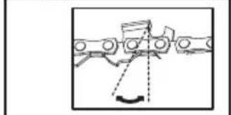
natural_image
Mechanical diagram showing a linkage mechanism with no visible text or symbols18, Dongwang Road, Suzhou Industrial
Park, Jiangsu 215123, P. R. China
INHOUDSOPGAVE
INLEIDING....134
ONDERDELENLIJST 136
PRODUCTVEILIGHEID 137
ASSEMBLAGE EN BEDIENING 140
VERVOER....148
ZAAG ONDERHOUD 148
REINIGEN....151
OPSLAG....151
PROBLEMEN OPLOSSEN....152
VEILIGHEIDSWAARSCHUWING
MONTAGE VAN DE ACHTERHANDGREEP (ZIE AFB. F1, F2)

KETTINGSMERING (ZIE AFB. J)
natural_image
Mechanical component diagram showing a lever with a 0° angle indicator (no text or symbols present)a:Vijlhoek; b:vijlpositie.
HET KETTINGTANDWIEL INSPECTEREN EN ONDERHOUDEN
| Accupack Amp Lader Amperage | ||
| KAC804 4 Ah KAC840 30 A |
18, Dongwang Road, Suzhou Industrial
Park, Jiangsu 215123, P. R. China
TARTALOMJEGYZÉK
BEVEZETŐ....156
AZ ALKATRÉSZEK LISTÁJA 158
TERMÉKBIZTONSÁG....159
KENÉS (LÁSD A J. ÁBRÁT)

18, Dongwang Road, Suzhou Industrial
Park, Jiangsu 215123, P. R. China
CUPRINS
INTRODUCERE....178
LISTADE COMPONENTE....180
INSTRUCTIUNIORIGINALE....181
ASAMBLARE ŞI OPERARE....185
TRANSPORTUL....192
ÎNTRETINEREA FERĂSTRĂULUI....192
CURĂȚAREA....195
DEPOZITAREA....196
DEPANAREA....197
DATE TEHNICE....198
RO
DECLARATIE DE CONFORMITATE....200
NTRODUCERE
Stimate Client,
MONTAJUL MÂNERULUI SPATE (VEZI FIG. F1, F2)
ASAMBLAREA CURELEI DE UMAR (VEZI FIG. G, H)

FASONAREA UNUI COPAC (TUNDERE)
INSPECTAREA \$I ÎNTRETINEREA ROȚII DE ANTRENARE A LĂNTULUI
CURĂȚAREA
18, Dongwang Road, Suzhou Industrial
Park, Jiangsu 215123, P. R. China
SPIS TREŚCI
WPROWADZENIE....201
LISTAKOMPONENTÓW....203
BEZPIECZEŃSTWOPRODUKTU....204
MONTAŻ I OBSŁUGA....208
TRANSPORT....216
KONSERWACJA PIŁY....216
CZYSZCZENIE 218
PRZECHOWYWANIE....219
ROZWIAZYWANIE PROBLEMÓW....220
DANE TECHNICZNE....221
DEKLARACJA ZGODNOŚCI....222
WPROWADZENIE
Drogi kliencie,
SMAROWANIE ŁAŃCUCHA (ZOBACZ RYS.J)

PRZYCINANIE DRZEW
Transport akumulatora
ABY WYCZYŚCIĆ SZYNY PROWADNICY
Before sharpening, please pay attention of the following steps: (Zobacz rys. R1)
KONTROLA I KONSERWACJA ZĘBATKI ŁAŃCUCHA
18, Dongwang Road, Suzhou Industrial
Park, Jiangsu 215123, P. R. China
OBSAH
ÚVOD....223
SEZNAM KOMPONENTÜ....225
PŮVODNÍ NÁVOD K POUŽÍVÁNÍ......226
SESTAVENÍ APOUŽÍVÁNÍ 230
PŘEPRAVA....237
ÚDRŽBA PILY 237
ČIŠTĚNÍ......240
SKLADOVÁNÍ 240
ODSTRAŇOVÁNÍ PROBLÉMŮ 241
TECHNICKÉ ÚDAJE....242
PROHLÁŠENÍ O SHODĚ 244
ÚVOD
Vážený zákazníku,
MONTÁŽ ZADNÍ RUKOJETI (VIZ OBR. F1, F2)
MAZÁNÍ ŘETĚZU (VIZ OBR. J)
KONTROLA A ÚDRŽBA ŘETĚZOVÉHO KOLA
UPOZORNĚNÍ: PŘED KONTROLOU JE NEZBYTNÉ VYPNOUT TYČOVOU PILU A VYJMOUT BATERII.

ČIŠTĚNÍ
The declared vibration total value may be used for comparing one tool with another, and may also be used in a preliminary assessment of exposure.

WARNING: The vibration emission value during actual use of the power tool can differ
from the declared value depending on the ways in which the tool is used dependant on the following examples and other variations on how the tool is used:
How the tool is used and the materials being cut or drilled.
The tool being in good condition and well maintained Using the correct accessory for the tool and ensuring it is sharp and in good condition.
The tightness of the grip on the handles and if any anti vibration accessories are used.
And the tool is being used as intended by its design and these instructions.
This tool may cause hand-arm vibration syndrome if its use is not adequately managed

WARNING: To be accurate, an estimation of exposure level in
the actual conditions of use should also take account of all parts of the operating cycle such as the times when the tool is switched off and when it is running idle but not actually doing the job. This may significantly reduce the exposure level over the total working period.
Helping to minimise your vibration exposure risk.
ALWAYS use sharp chisels, drills and blades
Maintain this tool in accordance with these instructions and keep well lubricated (where appropriate)
If the tool is to be used regularly then invest in anti vibration accessories. Plan your work schedule to spread any high vibration tool use across a number of days.
OCHRANA ŽIVOTNÍHO PROSTŘEDÍ

18, Dongwang Road, Suzhou Industrial
Park, Jiangsu 215123, P. R. China
TABLE OF CONTENTS
ÚVOD....245
ZOZNAMSÚČASTÍ......247
PÔVODNÝ NÁVOD NA POUŽITIE....248
MONTÁŽAOBSLUHA....252
PREPRAVA....259
ÚDRŽBA PÍLY 259
ČISTENIE 262
SKLADOVANIE....262
ODSTRAŇOVANIEPROBLÉMOV....263
TECHNICKÉPARAMETRE....264
PREHLÁSENIE O ZHODE....266
ÚVOD
Vážený zákazník,
USCHOVAJTE TIETO POKYNY
SYMBOLY
ZOSTAVA ZADNEJ RUKOVÄTE (POZRI OBR. F1, F2)


MASTENIE RETAZE (POZRI OBR. J)
KONTROLA A ÚDRŽBA KOLESA REŤAZE
ČISTENIE
18, Dongwang Road, Suzhou Industrial
Park, Jiangsu 215123, P. R. China
KAZALO VSEBINE
UVOD....267
SESTAVNI DELI....269
ORIGINALINSTRUCTIONS....270
SESTAVLJANJE IN NAČIN UPORABE 273
TRANSPORT....281
VZDRŽEVANJE ŽAGE....281
ČIŠČENJE 283
SHRANJEVANJE 284
ODPRAVLJANJE NAPAK....285
TEHNIČNI PODATKI....286
IZJAVA O SKLADNOSTI....288
UVOD
Spoštovana stranka,
SESTAVLJANJE ZADNJEGA ROČAJA (GLEJ SLIKI F1, F2)

MAZANJE (GLEJ SLIKO J)
- Rezila brusite s pilo od notranje strani rezalnih zob proti zunanji strani verige. (Glej sliko R3).
PREGLED IN VZDRŽEVANJE ZOBNIKA VERIGE
OPOZORILO: Pred pregledom obvezno izklopite žago na palici in odstranite baterijo.
ČIŠČENJE
18, Dongwang Road, Suzhou Industrial
Park, Jiangsu 215123, P. R. China
SADRŽAJ
UVOD....289
POPIS KOMPONENTI....291
ORIGINALNE UPUTE ZA RAD....292
SKUPINAI OPERACIJA....295
PRIJEVOZ....303
ODRŽAVANJE PILE 303
ČIŠĆENJE 305
SKLADIŠTENJE 306
OTKLANJANJE POTEŠKOĆA....306
TEHNIČKI PODACI....307
IZJAVA O SUKLADNOSTI....309
UVOD
Poštovani,
SASTAVLJANJE STRAŽNJE RUČKE (POGLEDAJTE SL. F1, F2)
PODMAZIVANJE (POGLEDAJTE SL. J)

VAŽNO: štapna pila nije napunjena uljem za vodilicu i lanac. Važno je prije uporabe napuniti ulje za vodilicu
NOTE: Fig K only applies for the battery pack with battery indicator light.
| Napomene | LED svjetlo | Stanje baterije |
| Svijetli pet zelenih svjetala. |  | 80% ≤ Razina napajanja ≤ 100% |
| Četiri zelena svjetla su upaljena. |  | 60% ≤ Razina napajanja < 80% |
| Tri zelena svjetla su upaljena. | [SBDD] | 40% ≤ Razina napajanja < 60% |
| Upaljena su dva zelena svjetla. | [DHSD] | 20% ≤ Razina napajanja < 40% |
| Jedno zeleno svjetlo svijetli. | [BY84] | 10% ≤ Razina napajanja < 20% |
| Trepće jedno zeleno svjetlo. | [XXWB] | 0% ≤ Razina napajanja < 10% |
PUNJENJE BATERIJKOG MODULA (Vidi sliku L)
Litij-ionska baterija je zaštićena od dubokog pražnjenja. Kada je baterija prazna, stroj se isključuje pomoću zaštitnog sklopa. Svaka baterija mora biti potpuno napunjena prije prve uporabe.
UKLANJANJE ILI UMETANJE BATERIJE (Vidi sliku M1, M2)
Nakon punjenja baterijski modulumetnite u utor za bateriju. Jednostavno guranje i blagi pritisak bit će dovoljni dok se ne začuje klik. Provjerite je li baterija dobro pričvršćena.
- Za držanje pile rabite obje ruke. Održavajte čvrsti stisak. Kada režete visoke ili udaljene predmete, držite stražnju ručku za oslonac. (Pogledajte sl. P5)
PODREZIVANJE STABLA (OBREZIVANJE) UPOZORENJE: izbjegavajte povratni udar. Povratni udar može rezultirati teškim ozljedama ili smrću.
-
Pomaknite se nekoliko centimetara (30 % od c) gore na grani. Napravite drugi rez s gornje strane grane. Nastavite rezati dok ne odrežete granu.
-
Napravite treći rez što bliže deblu stabla potpuno režući preostali dio. Upotrijebite donji dio vodilice za izvođenje ovog reza.
ZA BATERIJSKE ALATE
Preporučeni raspon temperature okoline za pražnjenje je -20 °C\~45 °C.
a:kut turpijanja; b:položaj turpije.
Kako naoštriti zube
- Pripremite okruglu turpiju za oštrenje rezača. (Vidi sliku R2). Napomena: Čvrsto stegnite vodilicu u škripcu prije oštrenja lanca. Uvjerite se da lanac nije „prikliješten“ i da se može slobodno kretati po vodilici. Provjerite je li lanac pravilno nategnut. (Vidi odjeljak „Zatezanje lanca“).
- Naoštrite rezače s pomoću turpije od unutarnje strane reznih zuba prema vanjskoj strani lanca. (Vidi sliku R3)
- Isturpijajte sve rezače s jedne strane vodilice.
-
Okrećite lančanu pilu uokolo i isturpijajte sve rezače na suprotnoj strani.
-
Pazite da duljina svih reznih zuba bude ista. Kako biste osigurali učinkovito, sigurno i glatko rezanje, isturpijajte visinu mjerača na 0,65 mm. Provjerite je li vodeći rub mjerača profila zaobljen. (Vidi sliku R4)
PROVJERA I ODRŽAVANJE LANČANIKA
18, Dongwang Road, Suzhou Industrial
Park, Jiangsu 215123, P. R. China
INDHOLDSFORTEGNELSE
INTRODUKTION ....310
KOMPONENTLISTE 312
ORIGINAL BRUGSANVISNING....313
SAMLING OG BETJENINGS....316
TRANSPORT 323
VEDLIGEHOLDELSE AF SAVEN OG SIKKERHED 324
RENG∅RING 326
OPBEVARING....326
FEJLFINDING....327
TEKNISK DATA....328
DK
KONFORMITETSERKLÆRING 329
INTRODUKTION
Kære kunde,
SAMLING AF SKÆREHOVED (SE FIG. A1, A2)
SAMLING AF BAGHÅNDTAG (SE FIG. F1, F2)
KÆDESM∅RING (SE FIG. J)

SÅDAN RENGÕRES SVÆRDETS SKINNER
a:Filevinkel; b:filens position.
EFTERSE OG VEDLIGEHOLDE KÆDEHJULET


RENG∅RING
18, Dongwang Road, Suzhou Industrial
Park, Jiangsu 215123, P. R. China
SISÄLLYSLUETTELO
JOHDANTO....330
KOMPONENTTILISTA 332
ALKUPERÄISET OHJEET 333
ASENNUS & OPERAATIO....336
KULJETUS....343
SAHAN HUOLTOTOIMENPITEET 344
PUHDISTUS....346
VARASTOINTI....346
VIANMÄÄRITYSTAULUKKO 347
TEKNISET TIEDOT 348
FIN
VAATIMUSTENMUKAISUUSVAKUUTUS 349
JOHDANTO
Hyvä asiakas,
VOITELU (KATSO KUVA J)

NOTE: Fig L1 only applies for the battery pack with battery indicator light.

PUUN KARSIMINEN (OKSIMINEN)
a:Viilauskulma; b:viilan asento.
KETJUPYÖRÄN TARKISTAMINEN JA KUNNOSSAPITO
PUHDISTUS
18, Dongwang Road, Suzhou Industrial Park, Jiangsu 215123, P. R. China
INNHOLDFORTEGNELSE
INTRODUKSJON....350
KOMPONENTLISTE 352
ORIGINAL DRIFTSINSTRUKS 353
MONTERING OG BRUK 356
TRANSPORT 363
SAVVEDLIKEHOLD....363
RENGJ∅RING....365
OPPBEVARING 366
FEILS∅KING....367
TEKNISKE DATA....368
NOR
SAMSVARSERKLÆRING 369
INTRODUKSJON
Kjære kunde,
BAKRE HÅNDTAKSENHET (SE FIG. F1, F2)
KJEDESM∅RING (SE FIG. J)

FORHOLD SOM KREVER VEDLIKEHOLD AV KJEDE OG LEDESKINNE:
a: Filingsvinkel; b: filposisjon.
INSPEKSJON OG VEDLIKEHOLD AV KJEDEHJUL
18, Dongwang Road, Suzhou Industrial
Park, Jiangsu 215123, P. R. China
INNEHÅLLSFÖRTECKNING
INTRODUKTION....370
KOMPONENTER....372
SÄKERHET....373
MONTERING & HANTERING....376
TRANSPORT....383
UNDERHÅLL AV SÅG....383
RENGÖRING....385
FÖRVARING....386
FELSÖKNING....387
TEKNISK INFORMATION....388
DEKLARATION OM ÖVERENSSTÄMMELSE....389
INTRODUKTION
Bästa kund,
MONTERING AV BAKRE HANDTAG (SE FIGUR F1, F2)
KEDJESMÖRJNING (SE FIGUR J)


BESKÄRA TRÄD (KVISTRENSNING)
a:Filvinkel; b:filposition.
Hur skären vässas
INSPEKTION OCH UNDERHÅLL AV KEDJEHJULET
18, Dongwang Road, Suzhou Industrial
Park, Jiangsu 215123, P. R. China

Copyright © 2024, Positec. All Rights Reserved.
AR01742702