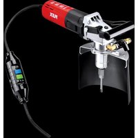
BHW 1549 VR - Drill Flex - Free user manual and instructions
Find the device manual for free BHW 1549 VR Flex in PDF.


| Product type | Drilling unit for natural stone, concrete and similar materials |
| Brand | Flex |
| Model | BHW 1549 VR |
| Mains voltage | 230 V / 50 Hz |
| Protection class | I |
| Input power | 1200 W |
| Output power | 700 W |
| No-load speed | 3500 - 10000 rpm |
| On-load speed | 3000 - 9000 rpm |
| Speed presetting | 6 positions (3300 to 10000 rpm) |
| Tool holder | M14 / M17 |
| Diamond drill diameters | 5 mm to 14 mm |
| Water connection | ½" with shut-off valve, max. pressure 6 bar |
| Weight (without cable) | 3.2 kg |
| Sound pressure level | 85.6 dB(A) |
| Sound power level | 96.6 dB(A) |
| Vibrations (solid drill ∅ 8 mm) | 3.2 m/s² |
| Vibrations (hollow drill ∅ 12 mm) | 4.8 m/s² |
| Safety device | PRCD circuit breaker with test and reset |
| Splash guard | Included, adjustable |
| Maintenance | Regular cleaning of ventilation slots, replacement of carbon brushes with original parts |
| Repairability | Repairs exclusively by manufacturer's approved after-sales service |
| Spare parts | Exploded views and lists at www.flex-tools.com |
| Disposal | Do not dispose of with household waste, recycle according to directive 2012/19/EC |
Frequently Asked Questions - BHW 1549 VR Flex
User questions about BHW 1549 VR Flex
0 question about this device. Answer the ones you know or ask your own.
Ask a new question about this device
Download the instructions for your Drill in PDF format for free! Find your manual BHW 1549 VR - Flex and take your electronic device back in hand. On this page are published all the documents necessary for the use of your device. BHW 1549 VR by Flex.
USER MANUAL BHW 1549 VR Flex
natural_image
Illustration of a mechanical power tool with a curved base and lever mechanism (no text or symbols)natural_image
Close-up of a car's front panel with a right-handled arrow pointing to a textured rectangular object (no text or symbols visible)natural_image
Mechanical assembly diagram showing a tool interacting with a mechanical component, with no visible text or symbols.Manager Research &
Development (R & D)
30.06.2015
Symbols used in this manual ..... 12
For your safety 12
Noise and vibration ..... 14
Overview 15
Technical specifications ..... 16
Operating instructions 17
Maintenance and care 19
Disposal information ..... 20
C€-Declaration of Conformity ..... 20
Exemption from liability 20
Symbols used in this manual

WARNING!
Denotes impending danger. Non-observance of this warning may result in death or extremely severe injuries.

CAUTION!
Denotes a possibly dangerous situation.
Non-observance of this warning may result in slight injury or damage to property.

NOTE
Denotes application tips and important information.
Symbols on the power tool

Before switching on the power tool, read the operating instructions!
Wear goggles!

Wear ear protection!

Disposal information for the old machine (see page 20)!
For your safety

WARNING!
Before using the power tool, please read and follow:
– These operating instructions,
- the "General safety instructions" on the handling of power tools in the enclosed booklet (leaflet-no.:315.915),
– the currently valid site rules and the regulations for the prevention of accidents.
This power tool is state of the art and has been constructed in accordance with the acknowledged safety regulations. Nevertheless, when in use, the power tool may be a danger tolife and limb of the user or a third party, or the power tool or other property may be damaged. The power tool may be operated only if it is
- a s i n t e n d e d ,
-in perfect working order.
Faults which impair safety must be repaired immediately.
Intended use
This drilling unit is designed
– for commercial use in industry and trade,
– for drilling through-holes and blind holes in natural stone, concrete and related materials using diamond drill bits and water,
– for free-hand drilling or for use with drill stands which are indicated in these instructions or recommended by the manufacturer,
– for use with tools and accessories which are indicated in this manual or recommended by the manufacturer.
The ermitted circumferential speed and the maximum diameter must not be exceeded.
Safety instructions for drilling unit

WARNING!
Read all safety instructions and other instructions. Failure to observe the safety instructions and other instructions may result in an electric shock, fire and/or serious injuries. Keep all safety instructions and other instructions in a safe place for the future.
■ This electric power tool is to be used as a drilling unit with the designated tools and accessories.
Observe all safety information, instructions, diagrams and data which you receive with the power tool.
If you do not observe the following instructions, an electric shock, fire and/or serious injuries may occur. If the electric power tool is not used as intended, the user may be exposed to hazards and may be injured.
■ Never use accessories which the manufacturer did not intend or recommend especially for this electric power tool. Just because you can attach the accessory to your electric power tool does not guarantee safe use.
■ Wear ear protection.
The effect of noise may result in loss of hearing.
■ When working, hold the electric power tool firmly with both hands on the designated handles and ensure that you have a secure footing.
The electric power tool is controlled more securely if held with both hands.
■ Use suitable detectors to detect concealed power supply cables or consult your local supply company.
Contact with electric cables may result in a fire and/or electric shock.
A damaged gas pipe may cause an explosion. Drilling into a water pipe will cause damage to property or may cause an electric shock.
- Keep the power cord away from rotating insertion tools. If you lose control of the appliance, the power cord could be severed or become caught and your hand or arm may strike the rotating insertion tool.
■ Secure the workpiece.
A workpiece is held more securely in a clamping device or vice than by hand.
■ Wait until the electric power tool has come to a standstill before putting it down.
The insertion tool may jam and cause you to lose control of the electric power tool.
■ These machines may be operated with the supplied PRCD switch only. Before using the machine, always check the PRCD switch.
■ Before performing any work on the electric power tool, pull out the mains plug. - Repairs to the electric power tool, such as replacement of the power cord, may be performed by the manufacturer's customer service only.
Noise and vibration
The noise and vibration values have been determined in accordance with EN 60745.
The A evaluated noise level of the power tool is typically:
– Sound pressure level: 85.6 dB(A);
– Sound power level: 96.6 dB(A);
- Uncertainty:
Total vibration value
(when drilling in natural stone):
– Emissions value:
(solid drill bit ∅ 8 mm) a _h=3.2m^2s
(hollow drill bit ∅ 12 mm) a h = 4.8 m ^2 /s
Uncertainty: 2

CAUTION!
The indicated measurements refer to new power tools. Daily use causes the noise and vibration values to change.

NOTE
The vibration emission level given in this information sheet has been measured in accordance with a standardised test given in EN 60745 and may be used to compare one tool with another. It may be used for a preliminary assessment of exposure. The declared vibration emission level represents the main applications of the tool.
However if the tool is used for different applications, with different accessories or poorly maintained, the vibration emission may differ.
This may significantly increase the exposure level over the total working period.
For a precise estimation of the vibration load the times should also be considered during which the power tool is switched off or even running, but not actually in use. 1.5
This may significantly decrease the exposure level over the total working period.
Identify additional safety measures to protect the operator from the effects of vibration such as: maintain the tool and the accessories, keep the hands warm, organisation of work patterns.

CAUTION!
Wear ear protection at a sound pressure above 85 dB(A).
Overview
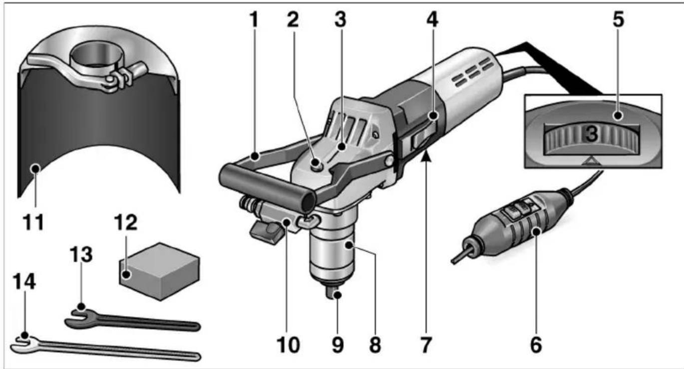
1 Bail handle
2 S p i n d l e l
3 Gearbox
4 S w i t c h r o
5 Dial for preselecting the speed
6 Power cord with PRCD circuit breaker
7 Rating plate
8 Clamping flange
9oToolholdek M14/17
10 Water connection with shut-off c valve e r
11 Water splash guard
12 Whetstone
13 Open-end wrench 19
14 Open-end wrench 17
Technical specifications
| Machine type Drilling unit | ||||
| Drill stand – BD 18 BD 06 | BED 18 BED 69 | |||
| Separate operating manual | ||||
| Mains voltage V/Hz 230/50 | ||||
| Protection class I | ||||
| Power input W 1200 | ||||
| Power output W 700 | ||||
| Load speed r.p.m. | 3000–9000 | |||
| Idle speed | r.p.m. | 3500–10000 | ||
| Tool holder | M14/17 | |||
| Diamond drill bit diameter/length/drilling depth | mm | 5/60/256/80/508/80/5010/80/50 | 6/88/588/103/7310/118/8812/128/9814/143/113 | 5/60/256/80/508/80/5010/80/50 |
| Water connection | 12" (for self-closing quick-action coupling), max. 6 bar | |||
| Weight (without power cord) | kg | 3.2 | 4.0 | 15.5 |
Operating instructions

WARNING!
Before performing any work on the electric power tool, pull out the mains plug.
Before switching on the power tool
Unpack the electric power tool and check that no parts are missing or damaged.
Connection to the power supply

WARNING!
These machines may be operated with the supplied PRCD switch only.
Beforeusing the machine, always check thePRCD switch.

NOTE
Before actuating the PRCD switch, check whether the electric power tool is switched off.
Always check the machine before use:
- Insert the mains plug into the socket.
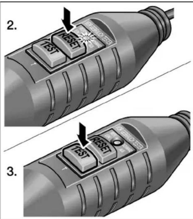
- Press "RESET" button.
The red indicator light must come on.
- Press "TEST" button.
The PRCD switch must switch off, the indicator light goes out.
- When the "RESET" button is pressed again, it must be possible to switch on the machine.

WARNING!
If the PRCD switch repeatedly switches off when the machine is switched on or if the PRCD switch does not trip, immediately disconnect the machine from the power supply.
Do not continue using the machine.
ThePRCDswitch may be replaced by themanufacturer's customer service only.
Connecting the water

WARNING!
Keep water away from the electric power tool and from people within the operating range. Do not switch on power tools which have not been connected correctly to the water supply. Regularly check that seals, shut-off valve and connectors function correctly.

NOTE
If there is no connection to the water supply mains, it is recommended to use the mobile water pressure tank WD 10 (capacity 10 litres, 4 m pressure hose, order no. 251.622).
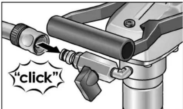
■ Attach 1/2" water hose to standard self-locking quick coupling.
■ Do not open shut-off valve until at the place of use and the tool is running.
■ When removing the hose, ensure that no water runs into the machine.
Attaching or changing diamond drill bit

WARNING!
Before performing any work on the electric power tool, pull out the mains plug.
■ Pull out the mains plug.

■ Grip tool holder with enclosed open-end wrench 17.
■ Screw diamond drill bit onto the shank.
■ Tighten drill bit with second open-end wrench 19.
Function test:
■ Insert the mains plug into the socket.
■ Switch on the electric power tool (without locking the button) and leave it running for approx. 30 seconds.
Check for imbalances and vibrations.
■ Switch off the electric power tool.
Preselecting the speed
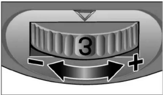
To set the operating speed, move the dial to the required value.
Setting Speed (min ^-1 )
1 3300
2 4600
36100
4 7300
5 8700
6 10000
Switching on and off
Brief operation without engaged switch rocker:
■ Push the switch rocker forwards and hold in position.
■ To switch off the power tool, release the switch rocker.
Continuous operation with engaged switch rocker:

CAUTION!
Following a power failure, the switched-on machine will start running again.
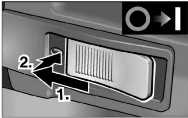
■ Push the switch rocker forwards and engage by pressing the front end.
natural_image
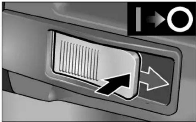
Close-up of a car's front panel with a scroll wheel and directional arrows (no text or symbols)■ To switch off the power tool, release the switch rocker by pressing the rear end.
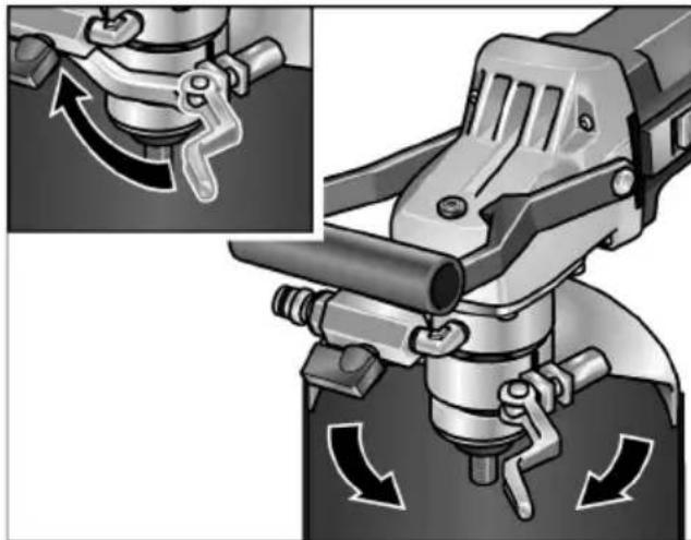
Attaching or adjusting water splash guard
i NOTE
The water splash guard is used to protect the user from splashing water. Thehood should be set in such a way to prevent water from being drawn in through the power tool.
natural_image
Mechanical assembly diagram showing a tool interacting with a mechanical component, with no visible text or symbols.■ Pull out the mains plug.
■ Loosen the clamping lever.
■ Push water splash guard onto the clamping flange and move into the required position.
■ Retighten the clamping lever.
Operating instructions
CAUTION!
If using a drill stand, follow the safety and operating instructions which can be found in the operating manual for the drill stand.
■ Attach diamond drill bit.
■ Move water splash guard into the required position.
■ Insert mains plug.
■ Check function of the PRCD.
Grip the handle with your right hand and the bail handle with your left hand.
■ Switch on the power tool.
■ Turn on water supply.
■ Start drilling.
■ If required, re-adjust the water supply.
■ After drilling, switch off the electric power tool. Diamond drill bit continues running briefly!
■ Turn off water supply.
■ At the end of work:
Thoroughly clean the electric power tool and accessories.
Maintenance and care
WARNING!
Before performing any work on the electric power tool, pull out the mains plug.
Cleaning
Regularly clean the power tool and ventilation slots. Frequency of cleaning is dependent on the material and duration of use.
Regularly blow out the housing interior and motor with dry compressed air.
Carbon brushes
The electric power tool features cut-off carbon brushes. When the cut-off carbon brushes reach their wear limit, the electric power tool switches off automatically.
i NOTE
Use only original parts supplied by the manufacturer for replacement purposes. If non-original parts are used, the guarantee obligations of the manufacturer will be deemed null and void.
Gears
NOTE
Do not loosen the screws on the gear head during the warranty period. Non-compliance will deem the guarantee obligations of the manufacturer null and void.
Repairs
Repairs may be carried out by an authorised customer service centre only.
Spare parts and accessories
| Spare-part/Accessory | Order |
| BD 06 drill stand for edge drilling | 254.186 |
| BD 18 drill stand with column guide | 290.343 |
| FLEX water pressure tank WD10 (10 l capacity, 6 bar pressure, 4 m pressure hose) | 251.622 |
Other accessories, in particular insertion tools, can be found in the manufacturer's catalogues.
Exploded drawings and spare-part lists can be found on our homepage:
www.flex-tools.com
Disposal information

WARNING!
Render redundant power tools unusable by removing the power cord.

EU countries only.
Do not throw electric power tools into the household waste!
In accordance with the European Directive 2012/19/EC on Waste Electrical and Electronic Equipment and transposition into national law used electric power tools must be collected separately and recycled in an environmentally friendly manner.

NOTE
Please ask your dealer about disposal options!
CE-Declaration of Conformity
no.
We declare under our sole responsibility that the product described under “Technical specifications” conforms to the following standards or normative documents:
EN 60745 in accordance with the regulations of the directives 2004/108/EC (until 19.04.2016), 2014/30/EU (from 20.04.2016), 2006/42/EC, 2011/65/EC.
Responsible for technical documents:
Klaus Peter WeinperEckhard F
Manager Research & Development (R & D)
Head of Quality Department (QD)
30.06.2015
Exemption from liability
The manufacturer and his representative are not liable for any damage and lost profit due to interruption in business caused by the product or by an unusable product.
The manufacturer and his representative are not liable for any damage which was caused by improper use of the power tool or by use of the power tool with products from other manufacturers.
Table des matières
natural_image
Close-up of a car's front panel with a scroll wheel and directional arrows (no text or symbols)natural_image
Mechanical assembly diagram showing a tool interacting with a mechanical component, with no visible text or symbols.Manager Research & Development (R & D)
Klaus Peter WeinperEckhard Rühle Head of Quality Department (QD)
30.06.2015
natural_image
Close-up of a mechanical knob with number 3 and directional arrows (no text or symbols)natural_image
Close-up of a car's front panel with a button and arrow indicator (no readable text or symbols)natural_image
Mechanical assembly diagram showing a tool interacting with a cylindrical component, with directional arrows indicating motion (no text or symbols present)Manager Research & Development (R & D)
Klaus Peter WeinperEckhard F Head of Quality Department (QD)
30.06.2015
natural_image
Close-up of a car's front panel with a right-handled arrow pointing to a textured screen (no text or symbols visible)natural_image
Mechanical assembly diagram showing a tool interacting with a cylindrical component, with directional arrows indicating motion (no text or symbols present)Manager Research & Development (R & D)
Klaus Peter WeinperEckhard F Head of Quality Department (QD)
30.06.2015
natural_image
Close-up of a car's front panel with a stylized arrow pointing to the button (no text or symbols visible)natural_image
Mechanical assembly diagram showing a tool interacting with a mechanical component, with no visible text or symbols.Manager Research & Development (R & D)
Klaus Peter WeinperEckhard F Head of Quality Department (QD)
30.06.2015
natural_image
Close-up of a mechanical knob with number 3 and directional arrows (no text or symbols)natural_image
Close-up of a car's front panel with a right-handled arrow pointing to a textured rectangular object (no text or symbols visible)natural_image
Mechanical assembly diagram showing a tool interacting with a cylindrical component, with directional arrows indicating motion (no text or symbols present)Manager Research & Development (R & D)
Klaus Peter WeinperEckhard F Head of Quality Department (QD)
30.06.2015
natural_image
Close-up of a mechanical knob with number 3 and directional arrows (no text or symbols)natural_image
Close-up of a car's front panel with a scroll wheel and directional arrows (no text or symbols)■ Frigør vippekontakten ved at trykke på bagerste ende for at slukke.
natural_image
Mechanical assembly diagram showing a robotic arm with rotating components and directional arrows indicating motion (no text or symbols)Manager Research & Development (R & D) 30.06.2015
Klaus Peter WeinperEckhard F Head of Quality Department (QD)
■ Hold verktøyholderen fast med vedlagte kjevenøkkel 17.
■ Skru diamantboret på spindelen.
■ Skru boret fast med en annen kjevenøkkel 19.
Funksjonstest:
natural_image
Close-up of a car's front panel with a right-pointing arrow and grid pattern, no visible text or symbolsnatural_image
Mechanical assembly diagram showing a tool interacting with a cylindrical component, with directional arrows indicating motion (no text or symbols present)Manager Research & Development (R & D)
Head of Quality Department (QD)
30.06.2015
natural_image
Close-up of a car's front panel with a stylized arrow pointing to the grille (no text or symbols)natural_image
Mechanical assembly diagram showing a tool interacting with a cylindrical component, with arrows indicating motion direction (no text or symbols present)Manager Research &
Development (R & D)
Klaus Peter WeinperEckhard F
Head of Quality
Department (QD)
30.06.2015
1 K a h v a
natural_image
Close-up of a car's front panel with a right-handled arrow pointing to a textured rectangular object (no text or symbols visible)natural_image
Mechanical assembly diagram showing a tool interacting with a cylindrical component, with no visible text or symbols.Manager Research & Development (R & D)
Klaus Peter WeinperEckhard I Head of Quality Department (QD)
30.06.2015
natural_image
Close-up of a car's front panel with a right-pointing arrow and grid pattern, no visible text or symbolsnatural_image
Mechanical assembly diagram showing a tool interacting with a cylindrical component, with directional arrows indicating motion (no text or symbols present)Manager Research &
Development (R & D)
30.06.2015
natural_image
Close-up of a car's front panel with a right-handled arrow pointing to a textured rectangular object (no text or symbols visible)natural_image
Mechanical assembly diagram showing a tool interacting with a cylindrical component, with arrows indicating motion direction (no text or symbols present)Manager Research & Development (R & D)
Head of Quality Department (QD)
30.06.2015
natural_image
Close-up of a car's front panel with a right-handled arrow pointing to a textured surface (no text or symbols visible)natural_image
Mechanical assembly diagram showing a tool interacting with a mechanical component, with no visible text or symbols.Manager Research & Development (R & D) 30.06.2015
Klaus Peter WeinperEckhard F
Head of Quality Department (QD)
1 Třmenová rukojeť
2 A r e t a c e v 3 P r̃ e v o d o v
4 Kolébkový vypínač
natural_image
Close-up of a mechanical knob with number 3 and directional arrows (no text or symbols)natural_image
Close-up of a car's front panel with a right-pointing arrow and grid pattern, no visible text or symbolsnatural_image
Mechanical assembly diagram showing a tool interacting with a cylindrical component, with arrows indicating motion direction (no text or symbols present)Klaus Peter WeinperEckhard F
Manager Research &
Head of Quality
Development (R & D)
Department (QD)
30.06.2015
natural_image
Close-up of a car's front panel with a right-handled arrow pointing to the grille (no text or symbols visible)natural_image
Mechanical assembly diagram showing a robotic arm with rotating components and directional arrows indicating motion (no text or symbols)■ Vytiahnite sietovú zástrčku.
■ Uvol'nite upínaciu páku.
■ Nastrčte ochranu proti striekaniu vody na upínaciu prírubu a do požadovanej polohy.
■ Upínaciu páku opät pevne utiahnite.
Pracovné pokyny

POZOR!
Manager Research & Development (R & D)
Klaus Peter WeinperEckhard F
Head of Quality
Department (QD)
30.06.2015
1 L i s a k ä e p
natural_image
Close-up of a car's front panel with a right-handled arrow pointing to the grille (no text or symbols visible)natural_image
Mechanical assembly diagram showing a robotic arm with rotating components and directional arrows indicating motion (no text or symbols)Manager Research &
Development (R & D)
Klaus Peter WeinperEckhard F
Head of Quality
Department (QD)
30.06.2015
1 Lenkta rankena
2 Veleno fiksatorius
3 Pavaros korpusas
4 Jungiklis
5 Sukimosi greičio reguliavimo
ratukas
6 Tinklo kabelis su apsauginiu nuotëkio srovës jungikliu (PRCD)
7 Irankio skydelis
natural_image
Close-up of a car's front panel with a right-handled arrow pointing to a textured rectangular object (no text or symbols visible)natural_image
Mechanical assembly diagram showing a tool interacting with a cylindrical component, with directional arrows indicating motion (no text or symbols present)1 Lokveida rokturis
natural_image
Close-up of a car's front panel with a right-pointing arrow and grid pattern, no readable text or symbolsnatural_image
Mechanical assembly diagram showing a tool interacting with a cylindrical component, with directional arrows indicating motion (no text or symbols present)Klaus Peter WeinperEckhard F
Manager Research & Development (R & D) 30.06.2015
Head of Quality Department (QD)
natural_image
Close-up of a mechanical knob with number 3 and directional arrows (no text or symbols)natural_image
Close-up of a car's front panel with a black arrow pointing to a textured surface, no visible text or symbols.natural_image
Mechanical assembly diagram showing a tool interacting with a cylindrical component, with directional arrows indicating motion (no text or symbols present)Manager Research & Development (R & D)
30.06.2015
Klaus Peter WeinperEckhard Rühle Head of Quality Department (QD)



- Symbols used in this manual
- WARNING!
- CAUTION!
- NOTE
- Symbols on the power tool
- For your safety
- Intended use
- Safety instructions for drilling unit
- Noise and vibration
- Overview
- Operating instructions
- Before switching on the power tool
- Connection to the power supply
- Always check the machine before use:
- Connecting the water
- Attaching or changing diamond drill bit
- Preselecting the speed
- Setting Speed (min -1 )
- Switching on and off
- Brief operation without engaged switch rocker:
- Continuous operation with engaged switch rocker:
- Attaching or adjusting water splash guard
- i NOTE
- Maintenance and care
- Cleaning
- Carbon brushes
- Gears
- Repairs
- Spare parts and accessories
- Disposal information
- CE-Declaration of Conformity
- no.
- Exemption from liability
- Table des matières
- Pracovné pokyny
- POZOR!
Brand : Flex
Model : BHW 1549 VR
Category : Drill