PerfectView CAM 360 AHD - Rear Camera DOMETIC - Free user manual and instructions
Find the device manual for free PerfectView CAM 360 AHD DOMETIC in PDF.


| Product Type | 360° rear view camera with bird's-eye view |
| Brand / Model | Dometic PerfectView CAM 360 AHD |
| Dimensions (camera) | See fig. 29, page 14 (not specified in the text) |
| Dimensions (control unit) | 126 x 86 x 26 mm |
| Weight (camera) | 100 g |
| Camera protection | IP69k |
| Image sensor | 1/3", 720p (1280 x 720 pixels) |
| Camera viewing angle | 180° |
| Video signal type | AHD/NTSC, 1 Vpp |
| Connection voltage | 9 V - 32 V DC |
| Power consumption (on) | < 700 mA (approx. 500 mA/12 V, 300 mA/24 V) |
| Power consumption (off) | approx. 2 mA |
| Operating temperature (camera) | -20 °C to +75 °C |
| Operating temperature (control unit) | -30 °C to +80 °C |
| Remote control battery | CR2025 |
| Main functions | 360° panoramic view, split screen, activation by turn signals/reverse gear, video recording on USB key, adjustable calibration |
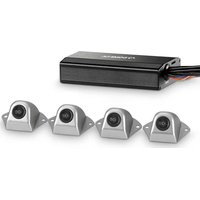
| Package contents | 4 cameras, controller, remote control, IR receiver, cables (front 6m, sides 10m, rear 17m), connection cable, bolts, adhesive tapes, USB key |
| Optional accessories | Calibration set 4 mats (9600000513), calibration set 2 mats (9600028360), monitor M75LAHD (9600012898) |
| Vehicle compatibility | Vehicles up to 10 m long (except construction machinery) |
| Safety | Disconnect the battery before installation; use max 3A fuses; do not expose to high-pressure cleaner; do not open the cameras |
| Cleaning and maintenance | Do not use high-pressure cleaner on the cameras; protect cables from gasoline; check sealing after installation |
| Repairability / Warranty | Legal warranty; attach invoice and defect description for repair; contact Dometic or dealer |
| Menu languages | French, English, German |
| Disposal | Packaging recyclable; used product and batteries: recycling center or retailer |
Frequently Asked Questions - PerfectView CAM 360 AHD DOMETIC
User questions about PerfectView CAM 360 AHD DOMETIC
0 question about this device. Answer the ones you know or ask your own.
Ask a new question about this device
Download the instructions for your Rear Camera in PDF format for free! Find your manual PerfectView CAM 360 AHD - DOMETIC and take your electronic device back in hand. On this page are published all the documents necessary for the use of your device. PerfectView CAM 360 AHD by DOMETIC.
USER MANUAL PerfectView CAM 360 AHD DOMETIC
EN 360^ camera system
Installation Manual. 15
DE 360° Kamerasystem
Monteringsanvising. 215
NO 360° Kamerasystem
Monteringsanvising 239
360° kamerajärestelma
Asennusohje 263
RU Bndeocnctema c o63opom 360°
HCTpykunno MOHTaxy. 287
PI System kamer 360^
Please read this instruction manual carefully before installation and first use, and store it in a safe place. If you pass on the product to another person, hand over this instruction manual along with it.
Table of contents
1 Explanation of symbols 15
2 Safety and installation instructions 16
3 Scope of delivery 17
4 Accessories 17
5 Intended use 18
6 Technical description 18
7 Installing the video system 19
8 Connecting the video system. 26
9 Video system settings 28
10 Warranty 37
11 Disposal. 37
12 Technical data 38
1 Explanation of symbols

WARNING!
Safety instruction: Indicates a hazardous situation that, if not avoided, could result in death or serious injury.

CAUTION!
Safety instruction: Indicates a hazardous situation that, if not avoided, could result in minor or moderate injury.

NOTICE!
Indicates a situation that, if not avoided, can result in property damage.

NOTE
Supplementary information for operating the product.
2 Safety and installation instructions
Please observe the safety instructions and stipulations issued by the vehicle manufacturer and service workshops.
The manufacturer accepts no liability for damage in the following cases:
- Faulty assembly or connection
- Damage to the product resulting from mechanical influences and incorrect connection voltage
- Alterations to the product without express permission from the manufacturer
- Use for purposes other than those described in the operating manual

WARNING! Failure to obey these warnings could result in death or serious injury.
-
Inadequate supply cable connections could result in short circuits, causing:
-
C a b l e f i r e s
- The airbag being triggered
- Damage to electronic control equipment
- Electrical malfunctions (indicators, brake light, horn, ignition, lights)

NOTICE! Damage hazard
- To prevent the risk of short circuits, always disconnect the negative terminal of the vehicle's electrical system before working on it. If the vehicle has an additional battery, its negative terminal should also be disconnected.
3 S C O P E O F D
| No. in fig. 1, page 3 | Quantity Label | |||
| 1 | 4 | C | a | m |
| 2 1 Controller | ||||
| 3 1 Remote control | ||||
| 4 1 IR receiver | ||||
| 5 1 Vehicle connection cable | ||||
| 6 4 Extension cable for cameras: | ||||
| 1x 6m (front) | ||||
| 2x 10m (left/right) | ||||
| 1x 17m (rear) | ||||
| - 14 Bolts with washers | ||||
| - 1 Vulcanising adhesive tape | ||||
| - 1 Double-sided adhesive tape (for infrared receiver) | ||||
| - 1 Flash drive | ||||
4 A c c e s o r i
Available as accessories (not included in the scope of delivery):
| Label Ref. no. | |
| Calibration set 4 mats | 9600000513 |
| Calibration set 2 mats | 9600028360 |
| Monitor M75LAHD | 9600012898 |
If you have questions regarding the accessories, please contact your local service partner.
5 Intended use

WARNING! Danger of personal injury by vehicle.
Video systems are designed merely as an additional aid for reversing, however this does not relieve you of the duty to take proper care when reversing, turning or driving forwards.

NOTE
- The CAM360AHD video system is not suitable for installation in construction machines.
- The video system is suitable for installation in vehicles up to 10m in length.
The CAM360AHD video system is designed for use in vehicles. The cameras transmit images in a 360^ panoramic view, providing you with a birds-eye view of the vehicle's environment to the sides, in front and behind.
The images of the cameras can be shown individually (split screen). The selection of an single camera image depends on the input signals from the turn signals and reverse gear. In addition, the selection can also be made via the remote control provided.
The video system is used to monitor the direct vehicle environment, e.g. when driving, changing lanes, manoeuvring or parking.
6 Technical description
Four 180^ wide wangle cameras are located on the front, the rear, and the left and right sides of the vehicle. A video processor merges the recorded images into a single image in real time that shows a birds-eye view of the vehicle and its surroundings at the front, rear and sides.
The camera system is switched on as soon as the vehicle is started.
The camera system provides a 360^ panoramic view and transmits the images in a birds-eye view of the vehicle's environment to the sides, in front and behind.
Depending on the settings, single cameras can be activated by input signals, e.g. by using a turn signal or reverse gear.
The control unit features four camera inputs and connects the cameras to the screens via a plug connector.
The control unit allows the following options:
- A permanent split screen, or a split screen triggered by a control signal
- Automatic full screen mode for the reversing camera as a rear mirror function
- Permanent full screen mode for the 360^ panorama view while the screen is upright
Videos from the cameras can be saved (flash drive) according to the circular buffer principle and played back within the camera system. A recording sequence lasts 5 minutes, then the next recording sequence begins automatically. Once the memory is full, the oldest file is overwritten automatically.
To play the videos on a computer, the video format H.264 must be supported.
7 Installing the video system
7.1 Information on installation

CAUTION! Risk of injury
- Select a location for the camera and attach it firmly enough so that it cannot under any circumstances fall off and injure bystanders (for example, by being knocked off by branches brushing over the roof of the vehicle).
- Secure the parts of the video system installed in the vehicle to ensure they cannot become loose under any circumstances (sudden braking, accidents) and cause injuries to vehicle occupants.
- Secure any parts of the system concealed by the bodywork in such a manner that they cannot be come loose or damage other parts or cables, or impair vehicle functions (steering, pedals, etc).
- Always follow the safety instructions issued by the vehicle manufacturer. Some work (e.g. on retention systems such as the AIRBAG etc.) may only be performed by qualified specialists.

NOTICE! Damage hazard
- The system may only be permanently installed after a successful test calibration.
- Before drilling or screwing, ensure that the respective cable lengths are long enough.
- To prevent damage when drilling, ensure there is sufficient space on the other side for the drill head to come out (fig. 3, page 5).
- Deburr all drill holes and treat them with a rust-protection agent.

NOTE
If installing the camera alters the vehicle size specified in the vehicle documents, your vehicle must be inspected by the appropriate authorities. This authority must note any such changes in your vehicle documents.
Please note the following:
-
When working on the following cables, only use insulated cable terminals, plugs and flat sockets:
-
30 (direct supply from positive battery terminal, acts as storage buffer for date and time)
- 15 (connected positive terminal, behind the battery)
- 31 (return cable from the battery, earth)
- Reversing light
- Left/right indicators
Do not use porcelain wire connectors.
- Use a crimping tool (fig. 27, page 4) to connect the cables.
-
Screw the cable when connecting cable 31 (earth)
-
using a cable terminal and serrated washer to one of the vehicle's earth bolts or
- screw the cable to the bodywork using a cable terminal and a self-tapping screw
Ensure there is a good earth connection.
If you disconnect the negative terminal of the battery, all data stored in the volatile memories will be lost.
-
The following data must be reset, depending on the vehicle equipment options:
-
R a d i o c o d e
- Vehicle clock
- T i m e r
- On-board computer
- Seat position
You can find instructions for making these settings in the operating manual.
7.2 Information on electrical connection

NOTICE! Damage hazard
- Cables and connections that are not properly installed will cause malfunctions or damage to components. Correct installation of cables and connections ensures lasting and trouble-free operation of the retrofitted components.
- The cables may not be exposed for long periods to solvents such as benzene, since solvents can damage the cable.
- When testing the voltage in electrical cables, only use a diode test lamp (fig. 2 8, page 4) or a voltmeter (fig. 2 9, page 4). Test lamps with a bulb (fig. 2 11, page 4) consume voltages which are too high and can damage the vehicle's electronic system.
- Insulate all connections.
- Secure the cables against mechanical wear by using cable binders or insulating tape, for example on existing cables.
The cameras are waterproof. However, the seals on the cameras cannot withstand a high-pressure cleaner (fig. 5, page 5). Therefore, you should observe the following instructions when handling the cameras:

NOTICE! Damage hazard
- Do not open the cameras, as this impairs the leak tightness and the function of the cameras (fig. 6, page 5).
- Do not pull at the cables, as this impairs the tightness and the function of the cameras (fig. 7, page 5).
The cameras are not suitable for use under water (fig. 8, page 5).
Observe the following instructions:
- As far as possible, use original ducts for laying the cables, or other suitable options such as panelling edges, ventilation grilles or dummy plugs. If no openings are available, you must drill holes for the cables. Check beforehand that there is sufficient space on the other side for the drill head to emerge.
- Wherever possible, lay cables inside the vehicle, as they are better protected there than outside.
If you do need to lay a cable outside the vehicle, ensure that it is well fastened (use additional cable ties, insulating tape etc.).
-
To prevent damage to the cables when laying them, ensure that they are far enough away from hot or moving vehicle components (exhaust pipes, drive shafts, light systems, fans, heaters, etc.). Use corrugated piping or other protective materials to protect against mechanical wear.
-
Use the vulcanising adhesive tape to protect the plug connections of the video connection cables against the ingress of water (fig. 9, page 6).
- When laying the cables (fig. 4, page 5), ensure:
- they are not kinked or twisted
- they do not rub on edges
- they are not laid in sharp-edged ducts without protection.
- Attach the cables securely in the vehicles to prevent tripping hazards. This can be performed by using cable binders, insulating tape or gluing in place with adhesives.
- Protect every through-hole made in the bodywork against water penetration, e.g. by using a cable with a sealant and by spraying the cable and the cable sleeve with sealant.

NOTE
Only start sealing through-holes when you have completed all installation work on the camera and have laid the required cable lengths.
7.3 Tools required
For installation and assembly you will need the following tools (fig. 2, page 4):
- Steel drill: 6 mm and 2.4 mm (1)
DriI1 (2) - Allen key: 2.5 mm (3)
- Measuring ruler (4)
- H a m m e r (5)
- Centre punch (6)
- Cr i m p i n g t o o l (7)
- 5 × measuring tape: at least 10 ~m
To establish and test the electrical connection, the following tools are required:
- Diode test lamp (fig. 2 8, page 4) or voltmeter (fig. 2 9, page 4)
Insulating tape (fig. 2 10, page 4) - Cable bushing sleeves
To fasten the cables, you may need additional cable binders.
7.4 Installing the cameras

NOTICE! Damage hazard
The system may only be permanently installed after a successful test calibration.
Finding the installation positions

NOTICE! Damage hazard
Ensure that the camera cable is not pinched or damaged. If necessary, use a 1 cm thick spacer under the camera base (fig. 12, page 7).
Please note the following:
- Ensure that the installation location of the camera is sufficiently firm (for example, to prevent the camera from being knocked down by branches that may brush the roof of the vehicle).
- The location on the body where you wish to attach the camera must be rigid enough to allow the camera to be tightly fastened.
- There must be sufficient space behind the chosen installation location to be able to carry out the mounting procedure.
- To obtain the best results, mount the cameras as high as possible and as close as possible to the centre of the vehicle.
- Ensure that the installation location of the camera is as upright as possible (fig. 13, page 7).
Proceed as follows:
Temporarily position the cameras using adhesive strips as shown in fig. 10, page 6 to fig. 14, page 7.
Temporarily connect the camera system according to the circuit diagram (fig. 15, page 8).
Perform a basic calibration as a test (refer to chapter "Calibrating the 360^ view" on page 31).
Mark the positions of the cameras.
Securing the cameras

NOTICE! Damage hazard
- Using a hammer and centre punch, gently pre-punch the previously marked points to prevent the drill head from slipping off.
- Deburr all drill holes that have been made in the sheet metal and apply rust-protection.
-
Place cable sleeves in all sharp edged ducts.
-
The most secure type of attachment is with screws fitted through the body.
- Check beforehand whether electrical cables can be damaged when the drill passes through the material (fig. 3, page 5).
- If you are not sure about the location you have chosen, ask your vehicle manufacturer or dealer.
Use the supplied self-tapping screws

NOTICE! Damage hazard
Self-tapping screws may only be fastened to steel metal with a minimum thickness of 1.5 mm .
Drill a hole of 6 mm for the cable entry (fig. 16, page 9).
Guide the camera cable into the vehicle interior (fig. 17, page 9).
Mark the holes for the mounting screws (fig. 18, page 9).
Remove the camera (fig. 18 2, page 9).
Drill two holes of 2.4mm for the camera bracket (fig. 19, page 9).
Guide the camera cable into the vehicle interior (fig. 20 1, page 9).
Screw on the camera with the included self-tapping screws (fig. 20 2, page 9).
If you would like to attach the camera with threaded bolts fitted through the construction

NOTICE! Damage hazard
Ensure that nuts cannot be pulled through the body shell when they are tightened. Use larger washers or metal plates if necessary.
Drill a hole of 6 mm for the cable entry (fig. 16, page 9).
Guide the camera cable into the vehicle interior (fig. 17, page 9).
Mark the holes for the mounting screws (fig. 18, page 9).
Remove the camera (fig. 18 2, page 9).
Drill two holes of 3.5mm for the camera bracket.
Guide the camera cable into the vehicle interior.
Screw on the camera with M3 x 20 mm threaded screws. Depending on the thickness of the construction, you may require longer threaded screws.
7.5 Installing the controller

NOTICE! Damage hazard
The control unit must not be exposed to direct sunlight.

NOTE
If you are using a flash drive to store the video data, route the USB cable (fig. 15 4, page 8) to an easily accessible location.
The control unit is supplied ready for installation.
Install the control unit in a location protected from water near the monitor, preferably under the dashboard or under the driver's seat.
Secure the control unit in place using the included bolts.
7.6 Installing the infrared receiver
For the infrared receiver, select an installation location that is in line of sight of the remote control.
Secure the infrared receiver with the included double-sided tape.
8 Connecting the video system

NOTICE! Damage hazard
- The lines for terminal 15, left indicator, right indicator and reverse must be secured on the vehicle side with a fuse rated no higher than 3 A. If this is not the case, then an additional fuse must be used at the corresponding consumer point.
- If the connection "MONITOR CTRL OUT" is not used, the copper end must be insulated. The load of this output must not exceed 150mA .

NOTE
Lay the camera cable so that, should you need to remove the camera, you can access the plug connection between the camera and the extension cable easily.
Connect the video system as shown in the connection diagram (fig. 15, page 8).
Insulate the plug of the camera adapter cable with the included vulcanising adhesive tape (fig. 9, page 6).
Key to the connection diagram
No. in
Fig. 15, Description of the connection
page 8
1 Monitor
2 Cameras
3 Controller
4 USB input
5 Black plug (jack type): Infrared receiver for the remote control
6 Yellow plug: Video output
7 Black plug ("FRONT"): Front camera
8 Black plug ("LEFT"): Left camera
9 Black plug ("RIGHT"): Right camera
10 Black plug ("REAR"): Rear camera
bk Black cable ("GND"): Connection to earth (terminal 31)
| No. in fig. 15, page 8 | Description of the connection |
| ye Yellow cable ("BATT"): Connection to continuous battery positive (terminal 30). Enables amongst others saving of date and time (recorder function). | |
| rd Red cable ("ACC"): Connection to ignition (terminal 15) | |
| og Orange cable ("TURN RIGHT IN"): Connection to the positive cable of the right indicator. When the right indicator is activated, the control box is activated via this cable and the corresponding individual camera is displayed. | |
| pk Pink cable ("TURN LEFT IN"): Connection to the positive cable of the left indicator. When the left indicator is activated, the control box is activated via this cable and the corresponding individual camera is displayed. | |
| gn Green cable ("REVERSE GEAR IN"): Connection to the positive cable of the reversing light. When the reverse gear is engaged, the control box is activated via this cable and the corresponding individual camera is displayed. | |
| bu Blue cable ("MONITOR CTRL OUT"): Control signal output for turning on a monitor (12 V control signal). | |
9 Video system settings

NOTE
The main menu cannot be activated when the indicator is activated or the reverse is engaged.
9.1 Control elements of the remote control
| No. in fig. 21, Page 10 | Button Description |
| 1 BACK button: Go to the previous menu in the main or submenu | |
| 2 OK or PLAY/PAUSE button: Activate main menu Confirm entry Play or interrupt recorded videos | |
| 3 SAVE button: Save | |
| 4 Minus or rewind button: Reduce value Fast rewind during video playback | |
| 5 0-9 Number keys: Enter numbers | |
| 6 Plus or forward button: Increase value Fast forward during video playback | |
| 7 Plus or minus button: No function assigned | |
| 8 △, ▽, ▪, □ Arrow buttons: Select front, rear, left or right camera Navigate in the main or submenu | |
| 9 ON/OFF button: Switch video transmission to the screen on or off | |
Use the remote control to navigate through the video menu.
9.2 Menu structure and displays
Press the button on the remote control.
Select " SETTINGS".
Enter the password "654321".
SETTINGS
BASIC VALUES
SAVE EXTERN
LOAD EXTERN
FACTORY RESET

Menu Description
BASIC VALUES See chapter "Setting BASIC VALUES" on page 30
SAVE EXTERN Save configuration including calibration onto external storage (flash drive)
LOAD EXTERN
- Load a new firmware
- Load externally configured configuration including calibration
FACTORY RESET Resets all settings to the factory defaults
9.3 Setting BASIC VALUES
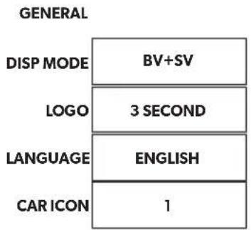
BASIC VALUES

SAVE

Setting Description
DISP MODE
BV: Bird's-eye View with vertical monitor
BV+SV: Split screen, left Bird's-eye View/right Single View
SV+BV: Split screen, left Single View/right Bird's-eye View
LOGO Duration for start-up logo
LANGUAGE Language selection: "ENGLISH", "DEUTSCH" (German), "FRANCAIS" (French)
CAR ICON Load different vehicle images from a flash drive
LEFT Adjust screen size to the left
RIGHT Adjust screen size to the right
TOP Adjust screen size to the top
BOTTOM Adjust screen size to the bottom
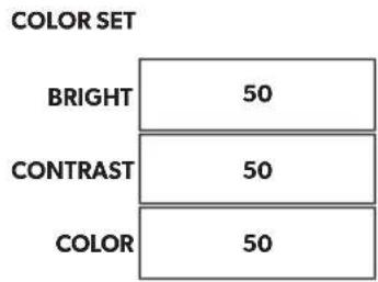
BRIGHT Set the brightness of the screen
CONTRAST Set the contrast of the screen
COLOR Set the colour of the screen
9.4 Calibrating the 360^ view

WARNING! Danger of personal injury by vehicle
- Ensure that all areas around the vehicle are displayed by the system. Blind spots represent a safety hazard.
- Blind spots can occur when the calibration mats were placed too far away from the vehicle. This particularly applies to front and rear.

NOTE
- When positioning the calibration mats, avoid reflective surfaces or strong shadows.
- It may be necessary to cover reflective surfaces such as the front pane with a cloth.
The following materials are required to calibrate the camera angles:
-
Calibration set (refer to chapter "Accessories" on page 17):
-
4 calibration mats with calibration pattern (2.0 × 1.6 ~m)
-
or 2 calibration mats with calibration pattern (1.2 × 5.4m)
-
5 measuring tapes with a minimum length of 10m
Adhesive tape - Optional: Straight beam, rail or board
Key to fig. 22, page 10 and fig. 23, page 11
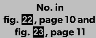

L Distance to the front and rear calibration mats
W Distance to the left and right calibration mats
Offset between front calibration mat and side calibrating mats (must be identical on both sides)
Optional: Position the beam, rail or board in front of the back wheels to act as a limit stop for positioning the side calibrating mats (fig. 24, page 11).
Position the calibration mats as shown in fig. 22, page 10 (4 calibration mats) or fig. 23, page 11 (2 calibration mats) and secure them with adhesive tape. - The calibration mats must be entirely visible.
Position the measure tapes as shown in fig. 22, page 10. - F o r m a rectangular shape around the vehicle.
Turn on the ignition to activate the system.
Press the button on the remote control.
Select "CALIBRATION".
Enter the password "654321".
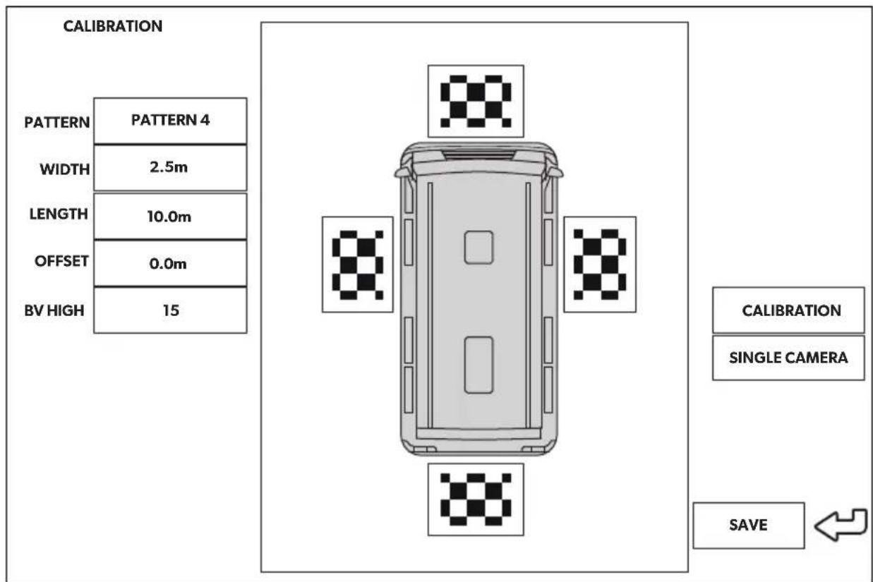
Calibration with 4 calibration mats
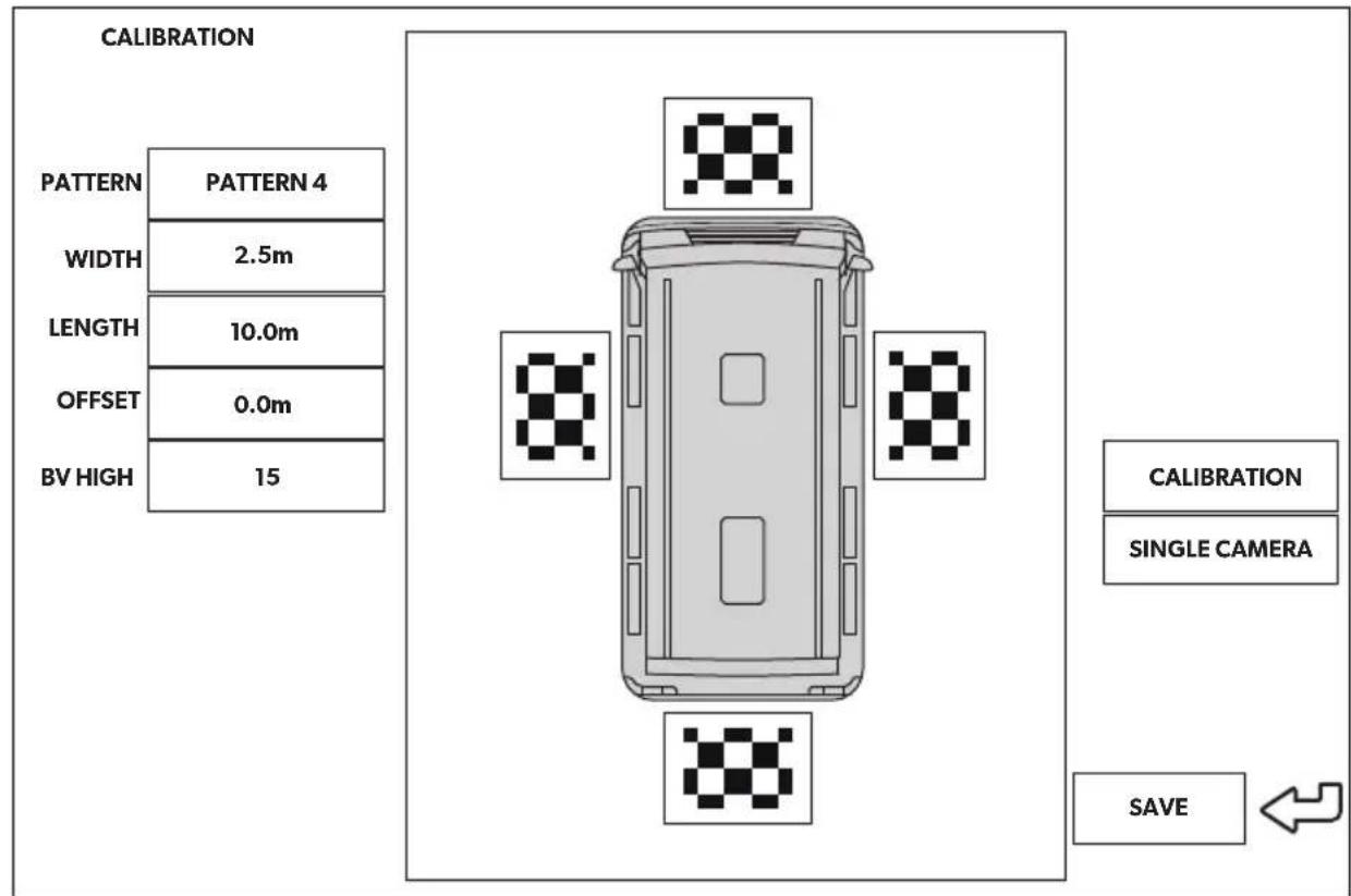
Adjust the value of "PATTERN" to "PATTERN 4".
Select the single camera views one at a time.
Check whether the camera angles are set so that the complete calibration mat can be seen.
If necessary, change the position of the calibration mat.
Measure the dimensions W, L and O in meter (fig. 22, page 10).
Enter the dimension W in m for the "WIDTH".
Enter the dimension L in m for the "LENGTH".
Enter the dimension O in m for the "OFFSET".
Select "CALIBRATION".
After the calibration, the display indicates "CALIBRATION SUCCESSFUL".
If the message "DETECT CLOTH Failed!!" is displayed:
Check whether:
-A strong shadow is on the calibration mat
- The complete calibration mat is displayed by the camera
Poor light conditions or reflections are present
Rectify the respective problems.
Select "CALIBRATION" again.
If you use the distance lines of the rear camera:
Select "SINGLE CAMERA".
Set "DIST LINE" to "ON" (refer to chapter "Setting a SINGLE CAMERA" on page 36).
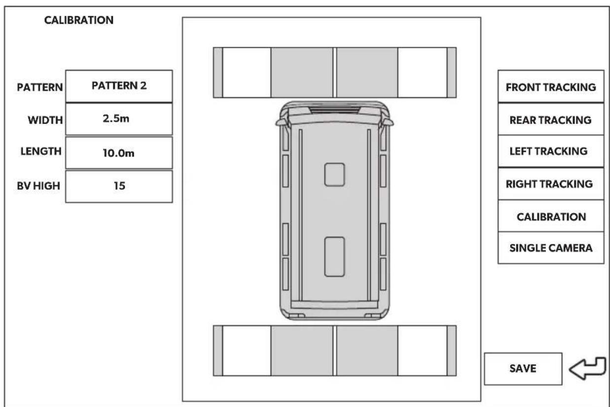
Calibration with 2 calibration mats
Adjust the value of „PATTERN“ to „PATTERN 2“.
Select the single camera views one at a time.
Check whether the camera angles are set so that two white rectangles on the calibration mats can be seen completely.
If necessary, change the position of the calibration mat.
Measure the dimensions W and L in meter (fig. 23, page 11).
Enter the dimension W in m for the "WIDTH".
Enter the dimension L in m for the "LENGTH".
Select "FRONT TRACKING".
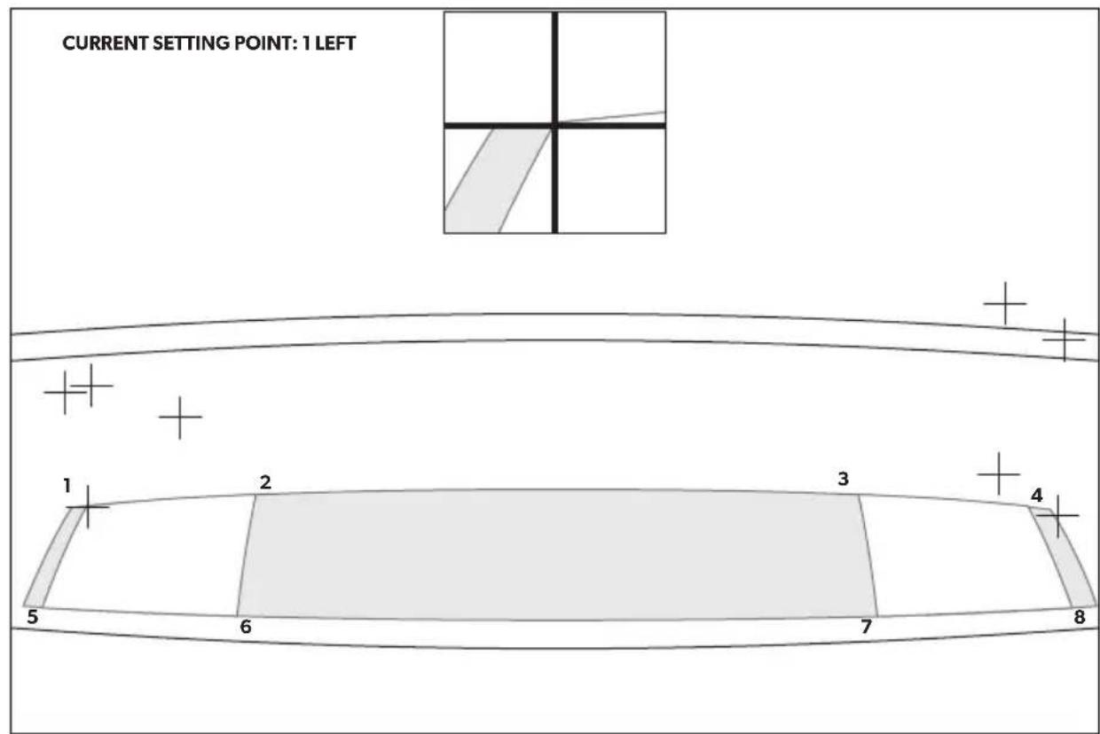
-
The view changes to the front camera. Eight red crosses and a zoom window are layered on top of the camera image. The zoom window shows an enlarged view of the currently active cross. The active cross is blinking.
Position the crosses with the arrow keys on the remote control. -
The crosses must be positioned on the corners of the white squares on the calibration mats.
- Confirm the position of each cross with the remote control (press "OK").
- After confirmation the colour of the active cross changes from red to green and the next cross becomes active.
Repeat this process for "REAR TRACKING", "LEFT TRACKING" and "RIGHT TRACKING". For each camera you have to adjust 8 crosses, 32 in total.
Select "CALIBRATION".
After the calibration, the display indicates "CALIBRATION SUCCESSFUL".
If the message "DETECT CLOTH FAILED!!" is displayed:
Illuminate the calibration mats as equally as possible.
Check whether:
-A strong shadow is on the calibration mat
- The complete calibration mat is displayed by the camera
- Poor light conditions or reflections are present
Rectify the respective problems.
Select "CALIBRATION" again.
Fine adjustment for offset

NOTE
For a fine adjustment in case of an offset, only change the parameters on the screen. It is not necessary to align the calibration mats or cameras as long as they are positioned rectangularly.
If the offset is asymmetrical like in fig. 25, page 12, position the calibration mats again. An asymmetrical offset can not be fixed via the software.
Select "CALIBRATION".
If you detect an offset in the front measuring tape (applicable to „PATTERN 4“ mode only) (fig. 26, page 12):
Change the "OFFSET" parameter.
Select "CALIBRATION".
Check the image.
Repeat these steps until no offset is visible.
If you see an offset in the side measuring tapes (fig. 27, page 13):
Change the "WIDTH" parameter.
Select "CALIBRATION".
Check the image.
Repeat these steps until no offset is visible.
If you detect an offset in the rear measuring tape (fig. 28, page 13):
Change the "LENGTH" parameter.
Select "CALIBRATION".
Check the image.
Repeat these steps until no offset is visible.
After fine adjustment:
Select "SAVE EXTERN" to also save the configuration including calibration to an external storage device (flash drive).
9.5 Setting a SINGLE CAMERA
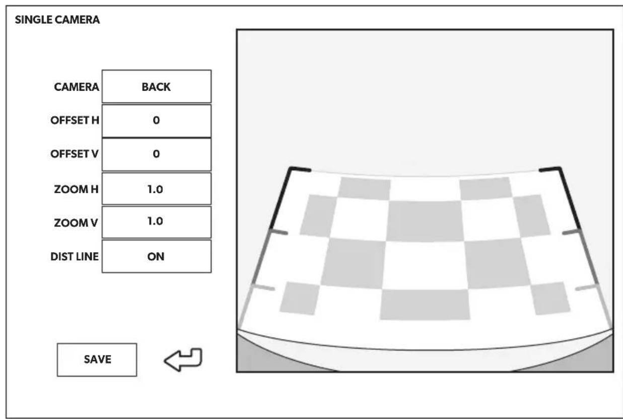
Setting Description
CAMERA“FRONT”,"RIGHT”,"REAR”,"LEFT"
OFFSET H Move camera image left or right
OFFSET V Move camera image up or down
ZOOM H Zoom camera image out
Setting Description
ZOOM V Zoom camera image in
DIST LINE
Only for the rear camera: Distance lines on/off (position adjustment applied automatically)
10 Warranty
The statutory warranty period applies. If the product is defective, please contact the manufacturer's branch in your country (see dometic.com/dealer) or your retailer.
For repair and warranty processing, please send the following items:
Defect components
A copy of the receipt with purchasing date
- A reason for the claim or description of the fault
11 Disposal
Place the packaging material in the appropriate recycling waste bins wherever possible.
If you wish to finally dispose of the product, ask your local recycling centre or specialist dealer for details about how to do this in accordance with the applicable disposal regulations.

Protect the environment!
Do not dispose of any batteries with general household waste.
Return defective or used batteries to your retailer or dispose of them at collection points.
12 Technical data
| PerfectView CAM360AHD | |
| Camera | |
| Image sensor: 1/3" | |
| Pixels: 720 (H) x 1280 (V) | |
| Horizontal resolution: 720p | |
| Sensitivity: 0.1 lux | |
| Viewing angle: 180° | |
| Dimensions (W x H x D): | fig. 29, page 14 |
| Weight: 100 g | |
| Protection class: IP69k | |
| Operating temperature: -20 °C to +75 °C | |
| Control unit | |
| Dimensions (W x H x D): | 126 x 86 x 26 mm |
| Video format: | AHD/NTCS, 1 Vpp (fig. 30, page 14) |
| Connection voltage: | 9 V---- - 32 V---- |
| Current consumption (switched on): | <700 mA (approx. 500 mA/12 V, approx. 300 mA/24V) |
| Current consumption (switched off): | approx.2 mA |
| Operating temperature: -30 °C to +80 °C | |
| Remote control battery: | CR2025 |
K cameras befestigen

6 Description technique
CotpydHnKMP3OdoJXhBHeCTNOTMeTKyo6N3MeHeHN KOHcTpyKu nn aBTOMo6nIa.
Co6nOdaIte cneDyUOuine yKa3aHn:
7.3 Tpe6yeMbI INHCTpyMeHT
BHIMAHHE! Pnck nobpexdeHna
9.4 Kanis6poBka 360^ Bnda

I P E D U N P E X K D E H N E! P n c k T p a B m b i B p e 3 y l b T a T e C T O L K H O B E H N A D B N X K Y U S E O C R A B T O M O 6 N I N C C Y E N O B E K O M
- Y6eIITecb, yTO BCE 3OHb BOKpyr aBTOMo6nIra OTO6paXaOTcra CnCTeMo. MeptBbIe 3OHb IpeIcTaNJrOT yrpo3y 6e3OnaChOCTN.
- Мергелям OTBOMKHyT, KOrda KaIIb6pOBOHbIe MaTbI 6bln pa3MeIeHbI cNIuKOM dAnEKO OT aBTOMo6nIa. 3TO OCO6eHHO OTHOCTcK NpeDHeN 3aDHeN qactn aBTOMo6nIa.

YKA3AHNE
- Пи установке калпброьчых MaTOВ n36eraite oТрахаюши новерхноcte и сильных TeHei.
- MoXeT 6bITb Heo6xOdIMo 3aKpbITb OTPaKaIOUne NOBepXHOCTN, TaKne KaK nepedHra NaHeNb, TkaHbIO.
PonacheHnK pnc. 22, ctp. 10 n pnc. 23, ctp. 11
Onu: PaononoXte 6anky, pebc nnn docky nepea3aHmKoNecamn, yTo6bOHN cnyxnn OpaHnHTeem dnn P03nHOHpOBaHna 6OKOBbIX KaNN6pOBOHyBix MaTOB (pnc.24, ctp.11).
Pacnoonoxnte kaH6pOBOHyIe MaIb, KaK NOKa3aHO Ha pnc. 22, ctp. 10 (4 kaH6pOBOHyX MaTa) nn pnc. 23, ctp. 11 (2 kaH6pOBOHyX MaTa), n 3akpeHnTe nx nnKoN neHToN.
-KaIIN6pOBOUHbIe MaTbI OJXHbI 6bITb IONHOCTbIO BnIHbI.
Pacnoonoxnte n3MepeHbIe neHbI, KaK noka3aHo Ha pnc. 22, ctp. 10.
- O6pa3ynte npmoYroJIbHKn BOKpyr aBTOMO6nIa.
Bknioynte 3axnraHne, yTo6bI aKTHBnPoBaTb cnCTemy.
HaxmTe KhoNky Ha npbTe nctaHIOHO ynpabneHn.
Bb6epnte «CALIBRATION».
BVeIte napoiB 654321
Kann6poBka c 4 kaH6poBOyhbIMMaTaMn
HacpoTe 3haeHne «PATTERN» Ha «PATTERN 4».
BbI6epnte BnDbl OTdEhBbIX KaMep no ODHOMy.
Проверът,установпьиллугькамерТаK,УTOбblMOЖHO6blNO yBnDEtB BeCb KaNN6poBOUHbIMaT.
Прин Heo6xOДIMOCtN,ИЗMeHnte nOToXeHne KaIb6pOBOuHOrO MaTa.
Измеръпазмерь W, Lи O в метрах (pnc. 22,ст. 10).
BVeIte pa3mep W (B metpax)ДЯ «WIDTH».
BVeIte pa3Mep L (B MeTpax) IЯ «LENGTH».
BVeIte pa3mep O (B MeTpax) nЯ «OFFSET».
BbI6epnTe «CALIBRATION».
√ Посné калпбровки на диспee отобрахаетс «CALIBRATION SUCCESSFUL».
Ecnn noBnIeTc coo6eHne «DETECT CLOTH FAILED!!»:
Поверпг:
- CnIbHa TeHb Ha KaIIb6pOBOuHOM MaTe
- Beçb kaɪnɪbɒpɔboʊhBI MAt OTo6pɑxæTcR kʌmepoɪ
-Плoxиусповя освеценя пи отрахене
YcTpaHInTe COOTBeTCTByIOUne npo6nembl.
dometic.com/sales-offices


