TV 328 - Thermometer Testboy - Free user manual and instructions
Find the device manual for free TV 328 Testboy in PDF.
| Product type | Infrared thermometer with dew point calculation |
| Brand | Testboy |
| Model | TV 328 |
| Dimensions | 190 x 130 x 55 mm |
| Weight | Approx. 280 g (battery included) |
| Power supply | 1 x 9 V battery |
| Battery life | Min. 100 hours of continuous use |
| Measuring range (IR) | -20 to +350 °C, resolution 0.1 °C |
| Accuracy (IR) +10 ~ +30 °C | ±1 % or 1.0 °C |
| Accuracy (IR) -10 ~ +90 °C | ±3 % or 3 °C |
| Accuracy (IR) +90 ~ +350 °C | ±5 % or 5 °C |
| Ambient measuring range | -10 to +40 °C (typ. ±1 °C) |
| Humidity measuring range | 10 – 90 % RH |
| Adjustable emissivity | 0.75 / 0.85 / 0.95 |
| Distance to spot ratio (D:S) | 12:1 |
| Response time | 0.5 s |
| Spectral response | 8 – 14 μm |
| Main functions | Non-contact infrared measurement, thermal bridge detection (green/yellow/red LED), mold alert, dew point calculation, °C/°F switching, backlight, laser circle |
| Auto power off | After approx. 25 seconds |
| Maintenance and cleaning | Clean the housing with a damp cloth without cleaning agent. Blow off the IR lens and gently brush with a fine brush |
| Safety | Do not point the laser at eyes. Avoid electromagnetic fields. Follow the safety instructions in the manual |
| Spare parts and repairability | Standard 9 V battery replaceable by user. No other spare parts intended |
Frequently Asked Questions - TV 328 Testboy
User questions about TV 328 Testboy
0 question about this device. Answer the ones you know or ask your own.
Ask a new question about this device
Download the instructions for your Thermometer in PDF format for free! Find your manual TV 328 - Testboy and take your electronic device back in hand. On this page are published all the documents necessary for the use of your device. TV 328 by Testboy.
USER MANUAL TV 328 Testboy
natural_image
Line drawing of a handheld device with a control panel and display screen (no text or symbols)Testboy® TV 328
Version 1.5
| de | Testboy® TV 328Bedienungsanleitung | 3 |
| en | Testboy® TV 328Operating instructions | 16 |
| fr | Testboy® TV 328Mode d'emploi | 29 |
| es | Testboy® TV 328Manual de instrucciones | 43 |
| pt | Testboy® TV 328Manual de instruções | 56 |
| it | Testboy® TV 328Istruzioni per l'uso | 68 |
| nl | Testboy® TV 328Gebruiksaanwijzing | 81 |
| da | Testboy® TV 328Betjeningsvejledning | 94 |
| sv | Testboy® TV 328Bruksanvisning | 107 |
| no | Testboy® TV 328Brukerhåndbok | 120 |
| fi | Testboy® TV 328Käyttöohje | 133 |
| tr | Testboy® TV 328Kullanım Kılavuzu | 146 |
| hu | Testboy® TV 328Használati utasítás | 159 |
| pl | Testboy® TV 328Instrukcja obsługi | 172 |
| cs | Testboy® TV 328Návod k obsluze | 185 |
| sk | Testboy® TV 328Návod na obsluhu | 198 |
| hr | Testboy® TV 328Upute za uporabu | 211 |
| lv | Testboy® TV 328Lietošanas pamācība | 224 |
Inhaltsverzeichnis
text_image
Technical diagram of a handheld device with numbered parts and labeled control panelDisplaybeschreibung
▶ Hoher Emissionsgrad (0.95)
text_image
Technical diagram of a device with labeled components and directional arrows indicating motion or movement.
text_image
Diagram showing two identical electrical circuit layouts with labeled components and warning symbols, likely for safety or hazard prevention.text_image
Diagram showing two identical scenarios with warning symbols and icons, one labeled 'F' (fire), the other 'F' (syringe)System Fehler
text_image
Warning sign with warning triangle and hazard symbol, surrounded by empty symbols and a sequence of broken shapes
General safety notes 17
Operation 20
Product description 20
Buttons and Components 20
Display Description 21
Turning On the Instrument 21
Safety 21
IRT Technology 21
Preparation 21
Emissivity 22
Setting the emissivity 22
Temperature measurement 22
Surface temperature measurement 23
Thermal Bridge Mode 23
Mold Warning Mode 24
°C/°F toggle 24
Automatic power-off 24
Size of measuring surface - distant-to-spot ratios (D/S) 25
Maintenance and cleaning 25
Changing the batteries 25
Error Messages 26
Temperature Sensor Not Acclimated 26
Ambient Temperature Outside Operating Range 27
Surface Temperature outside Measureable Range 27
System Error 27
Technical data 28
Safety notes
WARNING
An additional source of danger is posed my mechanical parts which can cause severe personal injury.
Objects can also be damaged (e.g., the instrument itself can be damaged).
WARNING
An electric shock can result in death or severe injury. It can also lead to property damage and damage to this instrument.
WARNING
Never point the laser beam directly or indirectly (on reflective surfaces) towards the eyes. Laser radiation can cause irreparable damage to the eyes. You must first deactivate the laser beam when measuring close to people.
General safety notes
Unauthorized changes or modifications of the instrument are forbidden – such changes put the approval (CE) and safety of the instrument at risk. In order to operate the instrument safely, you must always observe the safety instructions, warnings and the information in the "Proper and Intended Use" Chapter.
WARNING
Please observe the following information before using the instrument:
Do not operate the instrument in the proximity of electrical welders, induction heaters and other electromagnetic fields.
After an abrupt temperature fluctuation, the instrument should be allowed to adjust to the new temperature for about 30 minutes before using it. This helps to stabilize the IR sensor.
Do not expose the instrument to high temperatures for a long period of time.
Avoid dusty and humid surroundings.
Measurement instruments and their accessories are not toys. Children should never be allowed access to them!
In industrial institutions, you must follow the accident prevention regulations for electrical facilities and equipment, as established by your employer's liability insurance organization.
Proper and intended use
This instrument is intended for use in applications described in the operation manual only. Any other usage is considered improper and non-approved usage and can result in accidents or the destruction of the instrument. Any misuse will result in the expiry of all guarantee and warranty claims on the part of the operator against the manufacturer.

Remove the batteries during longer periods of inactivity in order to avoid damaging the instrument.

We assume no liability for damages to property or personal injury caused by improper handling or failure to observe safety instructions. Any warranty claim expires in such cases. An exclamation mark in a triangle indicates safety notices in the operating instructions. Read the instructions completely before beginning the initial commissioning. This instrument is CE approved and thus fulfils the required guidelines.
All rights reserved to alter specifications without prior notice.
© 2014 Testboy GmbH, Germany.
Disclaimer and exclusion of liability

The warranty claim expires in cases of damages caused by failure to observe the instruction! We assume no liability for any resulting damage!
Testboy is not responsible for damage resulting from:
failure to observe the instructions,
changes in the product that have not been approved by Testboy,
the use of replacement parts that have not been approved or manufactured by Testboy,
the use of alcohol, drugs or medication.
Correctness of the operating instructions
These operating instructions have been created with due care and attention. No claim is made nor guarantee given that the data, illustrations and drawings are complete or correct. All rights are reserved in regards to changes, print failures and errors.
Disposal
For Testboy customers: Purchasing our product gives you the opportunity to return the instrument to collection points for waste electrical equipment at the end of its lifespan.
The WEEE directive regulates the return and recycling of electrical appliances. Manufacturers of electrical appliances are obliged to take back and recycle all electrical appliances free of charge. Electrical devices may then no longer be disposed of through conventional waste disposal channels. Electrical appliances must be recycled and disposed of separately. All equipment subject to this directive is marked with this logo.
Disposing of used batteries
As an end user, you are legally obliged (by the relevant laws concerning battery disposal) to return all used batteries. Disposal with normal household waste is prohibited!
Contaminant-laden batteries are labelled with the adjacent symbol which indicates the prohibition of disposal with normal household waste.
The abbreviations used for heavy metals are:
Cd = Cadmium, Hg = mercury, Pb = lead.
You can return your used batteries for no charge to collection points in your community or everywhere where batteries are sold!
Certificate of quality
All aspects of the activities carried out by Testboy GmbH relating to quality during the manufacturing process are monitored permanently within the framework of a Quality Management System. Furthermore, Testboy GmbH confirms that the testing equipment and instruments used during the calibration process are subject to a permanent inspection process.
Declaration of Conformity
The product conforms to the present directives. For more detailed information, go to www.testboy.de
Operation
Thank you for choosing a Testboy ^® TV 328.
The Testboy® TV 328 has been constructed using state of the art technology and components. This device complies with the currently applicable standards and fulfils the requirements of all valid European and national guidelines.
Enjoy your new Testboy ^® TV 328!
The Testboy ^® TV 328 is an infrared temperature measurement instrument with determination of the due point.
Product description
Non-contact temperature measurements are ideally suited for applications where parts are rotating or energized or any such application involving parts where standard contact measurements are not possible. This device is supplied in a sturdy, practical pistol-shaped housing. It also features a quick response time and a wide temperature measuring range. The data-hold function allows the measure value to be saved temporarily. This device also features the following: an alarm function, a continuous measurement function, °C/°F toggle, min./max./avg. measurements, background lighting and a laser / LED spotlight combination that can be switched on.
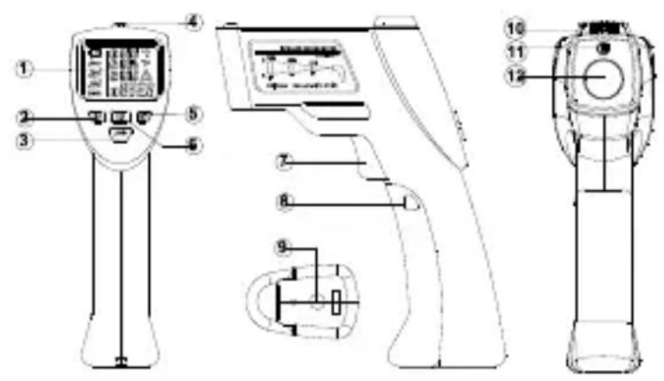
Buttons and Components
- LCD-display
- Surface temp. button
- Emissivity button
- LED indication
- Mold mode button
- Thermal bridge button
- Trigger
- Battery cover
- Tripod mounting hole
- Ambient sensor
- Laser pointer
- Infrarot sensor
text_image
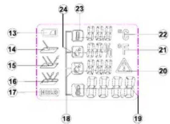
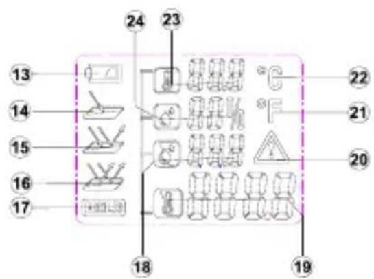
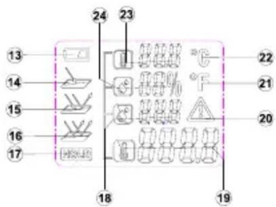
Technical diagram of a medical or laboratory device with numbered parts and labeled componentsDisplay Description
- Low Battery Indicator
- High Emissivity
- Medium Emissivity
- Low Emissivity
- Hold Reading
- Dew Point Temperature
- Surface Temperature
- Warning Symbol
- Degree Fahrenheit
- Degree Celsius
- Ambient Temperature
- Relative Humidity
text_image
13 14 15 16 17 24 23 22 21 20 18 19Turning On the Instrument
To turn the instrument on, press the trigger button. The meter will start up with the last settings that were used.
Safety

If the housing is opened, remember that some internal capacitors may still hold potentially lethal voltages even after the device has been switched off. In the event of errors or unusual operation, stop using the device and ensure that it cannot be used until it has been carefully checked out and repaired.
IRT Technology
An infrared thermometer detects the infrared radiation that an object emits. The sensor determines how much infrared radiation the object is giving off and the internal microprocessor converts that reading into a temperature reading. Using this method the thermometer can measure an object's temperature without touching the object. The laser-pointer builds a circle and only used to aim the target.
Preparation
Do not subject the instrument to extreme temperature variations. This can impair the accuracy of the instrument.
Avoid heavy impacts/dropping the instrument.
Avoid covering the temp/humidity sensor, infrared sensor or the laser pointers.
Emissivity
The emissivity is a value that is used to describe a material's energy radiation characteristic. The higher this value, the higher the ability of the material is to send out radiation. Many organic materials and surfaces have emissivity of approximately 0.95. Attached is a list of the emissivity values of several materials. Metallic surfaces or shiny materials have low emissivity. Therefore, the Testboy® TV 328 is fitted with an emissivity-setting feature. Despite this adjustable emissivity setting feature, we do not recommend taking measurements of shiny surfaces such as stainless steel. You will get more precise measured values if you blacken or tape over the surface to be measured. Measurements cannot be made through transparent surfaces, like through glass for example. You will actually measure the surface temperature of the glass instead.
Setting the emissivity
To correctly determine the surface temperature of an object, you need to set the emissivity accordingly. The instrument has 3 pre-set emissivity setting:
▶ High Emissivity (0.95)
Concrete (dry), bricks (red, course), sandstone (course), marble, roofing felt, stucco (course), mortar, gypsum, parquet flooring (matte), flooring panels, PVC, carpet, wallpaper (patterned), tiles (matte), glass, aluminum (anodized), enamel, wood, rubber, ice
▶ Medium Emissivity (0.85)
Granite, paving stone, fiberboard, wallpaper (lightly patterned), varnish (dark), metal (matte), ceramic, leather
▶ Low Emissivity (0.75)
Porcelain (white), varnish (light), cork, cotton
— To change the emissivity setting, press the correct emissivity degree desired.
button until the display shows the
Temperature measurement
To measure the temperature point the IR sensor's opening towards the object to be measured and press the key to measure the temperature.
Make sure that the measurement spot size is not larger than the object to be measured. The currently detected temperature is shown in the LCD. To locate the hottest spots of an object, point the Testboy® TV 328 at a location outside the desired area. Then search for the hottest point by moving the detector across the surface of the object in a zigzag pattern holding down the temperature measurement key all the while until you find the warmest spot.
After releasing the temperature measurement key the temperature detected will be shown in the display for approximately 25 seconds. During this time, "HOLD" will be shown. The device will switch itself off to save batteries after approximately 25 seconds.
Choose the unit you wish to be displayed (°C/°F) using the "AB" key.
The laser, when it is turned on, shows the mid-point of the measurement area approximately.
This means you can easily make accurate readings.
To activate the laser, press the temperature measurement key and the "Down" key until the laser is turned on. The LCD then shows the laser symbol. To turn the laser off again, press the temperature measurement key and the "Down" key again until the laser symbol disappears. When taking measurements in a dark environment you can turn on the background illumination for the display using the buttons temperature measurement and "Up".
Surface temperature measurement
- To measure the temperature of an object, Press the button to enter surface temperature mode.
— Point the instrument at the object and hold down the trigger. The laser pointers will activate showing the area in which the infrared sensor can see.
The display will show the current surface temperature 888.8 of the object within the measurement spot. After releasing the trigger the display will hold the current measurement.

Highly reflective or transparent surfaces can affect surface temperature measurements. If necessary, cover area with matte tape and allow tape to acclimate to the surface temperature before measuring.
Thermal Bridge Mode
Thermal bridge mode compares the surface temperature with the ambient temperature. If the temperature difference is large enough, the LED above the display will change from green to either yellow or red to indicate the possible presence of a thermal bridge.
To active thermal bridge mode, press the button to enter thermal bridge mode.
— Point the instrument at the object and hold down the trigger. The laser pointers will activate showing the area in which the infrared sensor can see.
— The display will show the current surface
- Temperature 888.6 of the object within the measurement spot along with the ambient temperature 888.6 After releasing the trigger the display will hold the current measurement.
— The LED above the display will indicate the possible presence of a thermal bridge.
▶ Green: Low temperature difference. No thermal bridge detected.
▶ Yellow: Medium temperature difference. Possible thermal bridge present. Check again at a later time to verify.
▶ Red: High temperature difference. Thermal bridge detected. The display will flash the surface temperature icon.

Check the insulation if a thermal bridge is detected.
Mold Warning Mode
Mold warning mode compares the surface temperature with the dew point temperature. Dew point temperature is calculated using the ambient temperature and the relative humidity. If the temperature difference is small enough, the LED above the display will change from green to either yellow or red to indicate the possible presence of mold.
- To activate mold warning mode, press the 📄 button to enter mold warning mode.
— Point the instrument at the object and hold down the trigger. The laser pointers will activate showing the area in which the infrared sensor can see.
— The display will show the current surface temperature 888.8 of the object within the
measurement spot, ambient temperature , relative humidity and
dew point temperature. After releasing the trigger the display will hold the current measurement.
— The LED above the display will indicate the possible presence of mold:
▶ Green: High temperature difference. No risk of mold detected.
▶ Yellow: Medium temperature difference. Possible mold risk present. Check again at a later time to verify.
▶ Red: Low temperature difference. High risk of mold detected. The display will flash the appropriate measurement that may be the cause.

Reduce the humidity or increase the ambient temperature if high risk of mold is detected.
The instrument cannot detect mold spores. The instrument only gives an indication that mold formation is possible at the given location.
°C/°F toggle
To switch between Celsius and Fahrenheit, hold the
button for approx. 3 seconds.
Automatic power-off
After approx. 25 s from releasing the trigger, the instrument will automatically turn itself off.
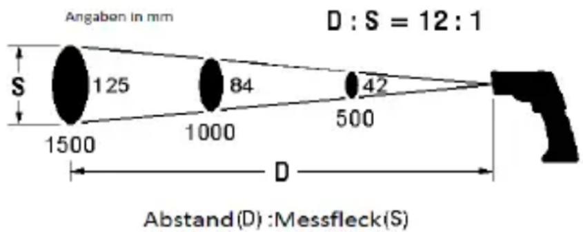
Size of measuring surface - distant-to-spot ratios (D/S)
In order to get accurate measuring results, the object to be measured must be larger than the measuring surface of the infrared thermometer. The detected temperature is then the average temperature of the measured surface area. The smaller the object is the shorter the distance to the infrared thermometer should be. The exact size of the measurement area can be seen in the following diagram. This is also printed on the outside of the instrument.

For exact measurements, the object to be measured should be at least twice the size of the measured surface area!
text_image
Angaben in mm D : S = 12 : 1 S 125 84 42 1500 1000 500 D Abstand(D) : Messfleck(S)Maintenance and cleaning

To avoid electrical shocks, do not allow liquid to penetrate the housing.
Clean the housing at regular intervals using a dry cloth without any cleaning agents. Do not use abrasive, scouring or solvent-based cleaners.
Blow loose dirt particles from the IR lens. Brush of any remaining dirt using a fine lens brush.
Changing the batteries
If the device is not to be used for a long time, remove the batteries and store the device in a place that is neither too hot nor too humid.
Do not leave used batteries in this device. Even anti-leakage batteries can corrode and release chemicals which can damage both the device and your health.
Procedure
When the battery symbol appears on the display, it indicates that the battery needs to be changed
| Turn off the device
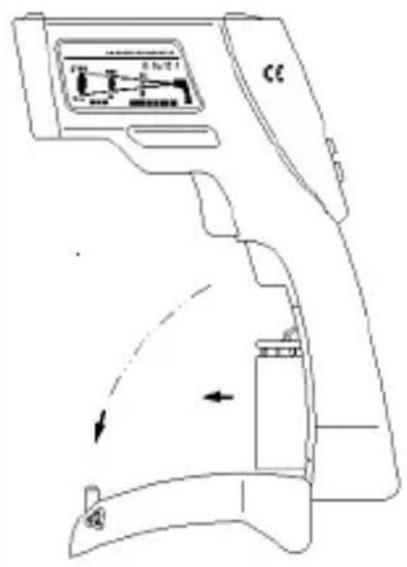
Press the casing at the OPEN symbols on both sides of the battery cover and pull it away from the meter to open the cover. See the drawing at the right
Replace the batteries with new ones of the same type, fold the cover back in place onto the handle and push it upwards.
text_image
Technical diagram of a device with labeled components and directional arrows indicating motion or movement.
Do not dispose of batteries in normal household rubbish. Use an authorised local collection point!
Error Messages
Temperature Sensor Not Acclimated
— The instrument has been exposed to severe temperature variations and needs time to acclimatize to the current environment.
- Keep the instrument in the current environment for approx. 10-30 minutes so it has enough time to adapt to the environment.
text_image
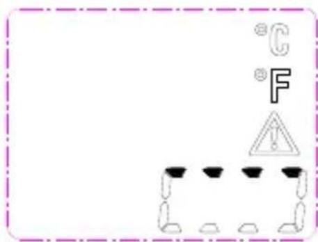
°C °F !Ambient Temperature Outside Operating Range
— The ambient temperature is either too high or too low for operation.
— Taking measurement in the current environment is not possible.
text_image
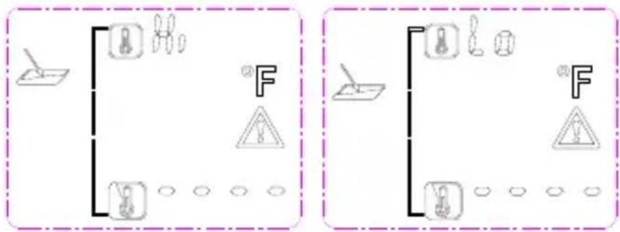
Diagram showing two identical electrical circuit layouts with labeled components and warning symbols, likely for safety or protection.Surface Temperature outside Measureable Range
— The surface temperature of the object within the measurement spot is either too high or too low for measurement.
– Temperature of this object cannot be measured.
text_image
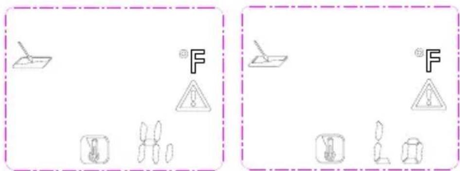
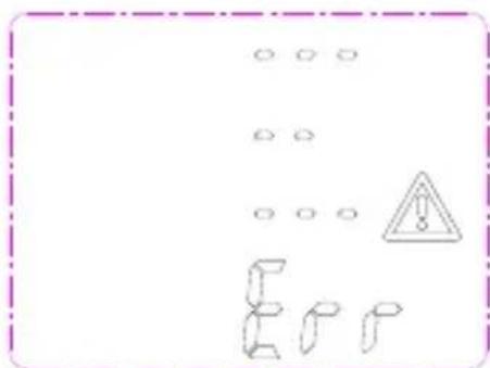
Diagram showing two identical scenarios with warning symbols and icons, one labeled 'F' in a dashed box.System Error
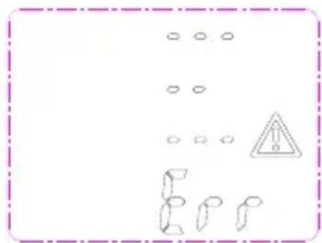
— The instrument has encountered a system error.
— To reset remove the battery, wait a few seconds, then re-insert battery.
text_image
Warning sign with warning triangle and hazard symbol, surrounded by circular symbols and broken shapes
If problem persists, the instrument may need to be taken in for service.
Technical data
| Operating temperature | -10 - +40 °C, < 80 % rel. humidity, non-condensing |
| Storage temperature | -20 - +60 °C, < 70% rel. humidity, without batteries |
| Power supply | 1 x 9 V block battery |
| Measurement range | -20 to +350 °C, resolution 0,1 °C |
| Accuracy (IR) +10 ~ +30 °C | ± 1% or 1.0 °C |
| Accuracy (IR) -10 ~ +90 °C | ± 3% or 3.0 °C |
| Accuracy (IR) +90 ~ +350 °C | ± 5% or 5.0 °C |
| Measurement range (environment) | -10° - +40 °C (typ. ±1 °C) |
| Measurement range (air humidity) | 10 - 90 % (<20 % ±3 %; 20 - 60 % ±2%; >60 % ±3 %) |
| Working height | < 2000 m |
| Emissivity | 0.75, 0.85, 0.95 |
| Response time | 0,5 s |
| Spectral resonance | 8 - 14 μm |
| Battery level display | Battery symbol in display at < 20 % |
| Distance to spot | 12:1 |
| Battery life | at least 100 hours continuous use |
| Dimensions | 190 x 130 x 55 mm |
| Weight | approx. 280 g (including batteries) |
| Display | Liquid crystal display |
| Accessories | Instruction manual, 9 V battery |
Table des matières
Cd = cadmium, Hg = mercure, Pb = plomb.
text_image
Technical diagram of a medical or diagnostic device with numbered components and labeled partstext_image
Technical diagram of a device with labeled components and directional arrows indicating motion or movement.
text_image
Diagram showing safety symbols and equipment labels including a tool, warning sign, and hazard symbolnatural_image
Pure electrical circuit lines without any symbols
natural_image
Pure electrical circuit lines without any symbolsErreur système
text_image
Warning sign with warning symbol, circular symbols, and broken shapes below
Si l'erreur subsiste, contacter notre service.
text_image
Technical diagram of a medical or laboratory device with numbered parts and labeled componentstext_image
Technical diagram of a device with labeled components and directional arrows indicating motion or movement.
text_image
Diagram showing two identical electrical circuit symbols with warning symbols and circuit components, each enclosed in a dashed border.text_image
Diagram showing two identical electrical circuit symbols with warning symbols and labeled components, likely representing a circuit hazard or safety hazard.Error del sistema
text_image
Warning sign with warning symbol and broken symbols, including a triangular warning triangle and repeated 'E' characters
text_image
Technical diagram of a medical device with numbered components and labeled partsDescrição do visor
text_image
Technical diagram of a device with labeled components and directional arrows indicating motion or movement.
text_image
Diagram showing electrical circuit components with symbols and labels, including switches, diodes, and warning signs
flowchart
graph TD
    A["Document Icon"] --> B["Tool Icon"]
    A --> C["Tools Icon"]
    A --> D["Warning Symbol"]
    A --> E["Crosshairs Icon"]
    B --> F["F"]
    C --> G["Warning Symbol"]
    D --> H["Crosshairs Icon"]
    E --> I["Crosshairs Icon"]
natural_image
Pure electrical circuit lines without any symbols
text_image
Diagram showing electrical components and symbols including a switch, warning triangle, battery, lamp, and bulbErro no sistema
text_image
Warning sign with warning symbols and a warning triangle, surrounded by abstract geometric shapes
text_image
Technical diagram of a medical or laboratory device with numbered components and labeled partsLegenda display
text_image
Technical diagram of a device with labeled components and directional arrows indicating motion or movement.
text_image
Diagram showing electrical circuit components with symbols for fuse, warning sign, and ground symbols
flowchart
graph TD
    A["Tool"] --> B["Power Supply"]
    A --> C["Load"]
    A --> D["Load"]
    B --> E["Warning Triangle"]
    C --> E
    D --> E
    style A fill:#f9f,stroke:#333
    style B fill:#ccf,stroke:#333
    style C fill:#cfc,stroke:#333
    style D fill:#fcc,stroke:#333
natural_image
Pure electrical circuit lines without any symbols
natural_image
Pure electrical circuit lines without any symbolsErrore di sistema
text_image
Warning sign with warning symbol and abstract shapes, including a triangle and broken shapes
Cd = cadmium, Hg = kwik, Pb = lood.
text_image
Technical diagram of a handheld device with numbered parts and control panel layoutDisplaybeschrijving
text_image
Technical diagram of a medical device with labeled components and directional arrows indicating movement or flow.
text_image
Diagram showing two identical electrical circuit setups with labeled components and warning symbolstext_image
Diagram showing two identical scenarios with warning symbols and icons, one labeled 'F' in a dashed box.Systeemfout
text_image
Warning sign with warning triangle and abstract shapes, enclosed in a dashed border
text_image
Technical diagram of a medical or laboratory device with numbered components and labeled partstext_image
Technical diagram of a medical device with labeled components and directional arrows indicating movement or flow.
text_image
Diagram showing electrical circuit symbols including a lamp, fuse, warning triangle, and ground symbols with labels like 'F' and 'o'.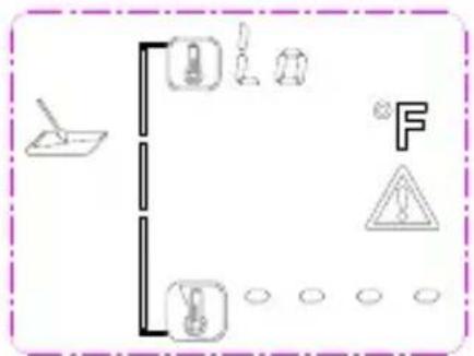
text_image
Diagram showing electrical circuit symbols including a lamp, fuse, capacitor, warning symbol, and ground connectiontext_image
Diagram showing electrical symbols including a switch, warning sign, and various circuit components with Chinese characters.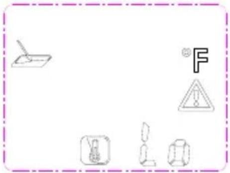
natural_image
Pure electrical circuit lines without any symbolsSystemfejl
text_image
Safety warning sign with hazard symbol and cartoon figures, enclosed in a dashed border
Cd = kadmium, Hg = kvicksilver, Pb = bly.
text_image
Technical diagram of a medical or laboratory device with numbered parts and labeled componentstext_image
Technical diagram of a device with labeled components and directional arrows indicating motion or movement.
text_image
Diagram showing two identical electrical circuit symbols with warning symbols and ground symbols, labeled 'F' in Chinese.text_image
Diagram showing two identical scenarios with warning symbols and icons, one labeled 'F' in a dashed border.Systemfel
text_image
Warning sign with warning triangle and broken symbols, enclosed in a dashed border
text_image
Technical diagram of a handheld device with numbered components and labeled parts in ChineseDisplay Description
- Indikator for lavt batterinivå
- High Emissivity
- Medium Emissivity
- Low Emissivity
- Lagring
- Punkttemperatur
- Overflatetemperatur
- Varselsymbol
- Grader Fahrenheit
- Grader Celsius
- Omgivelsestemperatur
- Relativ fuktighet

text_image
13 14 15 16 17 24 23 22 21 20 18 19Å slå på instrumentet
natural_image
Technical line drawing of a handheld device with internal components and directional arrows (no text or symbols)
Ikke kast batterier i vanlig husholdningsavfall. Bruk et autorisert innsamlingssted!
Feilmeldinger
text_image
Diagram showing electrical circuit components including a lamp, switches, and warning symbols with labels like 'F' and '△'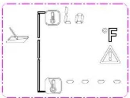
text_image
Diagram showing safety symbols and vehicle positions with labels like 'F' and warning signsOverflatetemperatur utenfor målbart område
text_image
Diagram showing electrical symbols including a switch, warning triangle, and various electrical components with Chinese characters.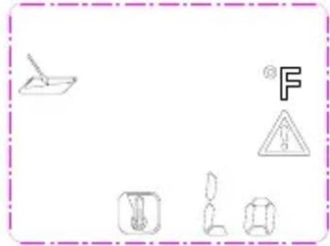
text_image
Diagram showing various electrical symbols and warning signs, including a pencil, a warning triangle, and various electrical components.Systemfeil
text_image
Warning sign with warning triangle and broken pipe symbols, enclosed in a dashed border
Cd = Kadmium, Hg = Elohopea, Pb = Lyijy.
text_image
Technical diagram of a medical or diagnostic device with numbered components and labeled partsNäytön kuvaus
text_image
Technical diagram of a medical device with labeled components and directional arrows indicating movement or flow.
text_image
Diagram showing electrical circuit components including a switch, fuse, and warning symbols with labels like 'F' and 'A'.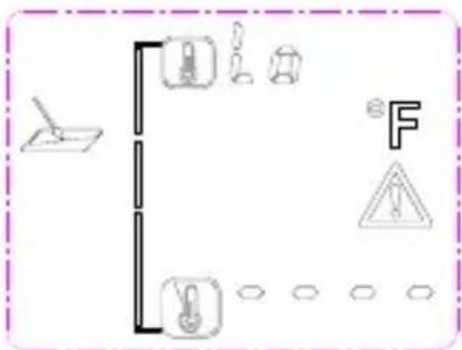
text_image
Diagram showing various electrical or mechanical symbols including a switch, battery, fuse, warning symbol, and circuit components.text_image
Diagram showing various electrical symbols including a lamp, warning sign, and circuit components with Chinese characters.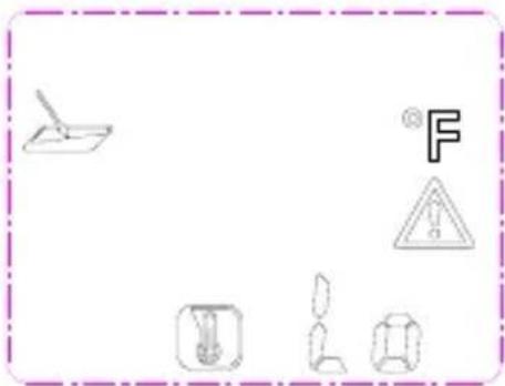
natural_image
Pure electrical circuit lines without any symbolsJärjestelmävirhe
text_image
Warning sign with warning symbol and hazard symbol, surrounded by scattered circles and broken shapes
text_image
Technical diagram of a medical or diagnostic device with numbered parts for identification and assembly reference.Ekran Açıklaması
text_image
Technical diagram of a device with labeled components and directional arrows indicating motion or movement.
text_image
Diagram showing two electrical circuit configurations with switches, diodes, and warning symbols for thermal protection.text_image
Diagram showing two identical electrical circuit symbols with warning signs and component illustrations, labeled 'F' in each panel.Sistem Hatası
text_image
Warning sign with warning symbol and abstract shapes, including a triangle and broken blocks
Cd = kadmium, Hg = higany, Pb = ólom.
text_image
Technical diagram of a handheld device with labeled parts including display, control panel, and sensor componentsKijelző leírása
text_image
Technical diagram of a device with labeled components and directional arrows indicating motion or movement.
text_image
Diagram showing two identical electrical circuit layouts with labeled components and warning symbols, likely for safety or hazard prevention.text_image
Diagram showing two identical electrical circuit symbols with warning symbols and labeled components, enclosed in a dashed border.Rendszerhiba
text_image
Warning sign with warning triangle and abstract shapes, surrounded by dots and a sequence of symbols
text_image
Technical diagram of a medical or laboratory device with numbered parts and labeled componentsOpis wyświetlacza
natural_image
Technical line drawing of a handheld device with control panel and directional arrows (no text or symbols)
text_image
Diagram showing two identical electrical circuit layouts with fuse, warning symbols, and ground symbols, each containing a labeled component.text_image
Diagram showing two identical electrical circuit symbols with warning signs and component illustrations, labeled 'F' in Chinese.Błąd systemu
text_image
Warning sign with warning triangle and broken symbols, likely indicating a hazard or hazard warning.
text_image
Technical diagram of a handheld device with numbered parts and labeled componentsPopis displeje
text_image
Technical diagram of a medical device with labeled components and directional arrows indicating movement or flow.
text_image
Diagram showing two identical electrical circuit symbols with labeled components and warning symbols, likely representing a power or protection mechanism.text_image
Diagram showing two identical scenarios with warning symbols and mechanical components, each labeled with a letter 'F' and warning triangle.Systémová chyba
text_image
Warning sign with warning symbol and hazard symbol, surrounded by repeated 'E' icons
text_image
Technical diagram of a medical or laboratory device with numbered parts for identification and assembly reference.Popis displeja
- Indikátor vybitia batérie
- Vysoká emisivita
- Stredná emisivita
- Nízka emisivita
- Uchovanie údaja
- Teplota rosného bodu
- Teplota povrchu
- Symbol upozornenia
- Stupne Fahrenheit
- Stupne Celzia
- Teplota okolia
- Relativna vlhkost'
text_image
13 14 15 16 17 24 23 22 21 20 18 19Zapnutie prístroja
text_image
Technical diagram of a handheld device with labeled components and directional arrows indicating motion or movement.
text_image
Diagram showing two identical electrical circuit symbols with warning symbols and labeled components, enclosed in a dashed border.Teplota povrchu mimo meracieho rozsahu
text_image
Diagram showing two identical electrical circuit symbols with warning symbols and labeled components, likely representing a circuit hazard or safety hazard.Systémová chyba
text_image
Warning sign with warning symbol and abstract shapes, including a triangle and broken bars
text_image
Technical diagram of a handheld device with numbered parts and labeled control panelOpis zaslona
- indikator baterije
- viši emisijski stupanj
- srednji emisijski stupanj
- niski emisijski stupanj
- Hold prikaz
- temperatura točke rošenja
- temperatura površine
- upozorenje-simbol
- stupnjeva Fahrenheit
- stupnjeva Celziusa
- temperatura okoline
- relativna vlažnost zraka
text_image
13 14 15 16 17 24 23 22 21 20 18 19Mjerenje temperature
text_image
Technical diagram of a device with labeled components and directional arrows indicating motion or movement.
text_image
Diagram showing two identical electrical circuit layouts with labeled components and symbols, possibly representing a power or safety system.text_image
Diagram showing two identical electrical circuit symbols with warning signs and component illustrations, each enclosed in a dashed border.Sistemska greška
— Utvrđena je greška u sistemu.
— Uklonite bateriju na par sekundi da bi mogli ponovno pokrenuti sistem.
text_image
Warning sign with warning triangle and abstract shapes, surrounded by blank circles
Nastavi li uređaj prikazivati pogrešku na zaslonu, kontaktirajte naš servis.
Tehnički podatci
| Radna temperatura | -10 - +40 °C, < 80 % rel. vl., ne kondenzirajuća |
| Temperatura skladištenja | -20 - +60 °C, < 70% rel. vl., bez baterije |
| Opskrba strujom | 1 x 9 V blok baterija |
| Mjerno područje (IR) | -20 do +350 °C, razlučivost 0,1 °C |
| Točnost (IR) +10 ~ +30 °C | ± 1% ili 1,0 °C |
| Točnost (IR) -10 ~ +90 °C | ± 3% ili 3 °C |
| Točnost (IR) +90 ~ +350 °C | ± 5% ili 5 °C |
| Mjerno područje (okoliš) | -10° - +40 °C (tip. ±1 °C) |
| Mjerno područje (vlažnost zraka) | 10 – 90 % (<20 % ±3 %; 20 - 60 % ±2 %; >60 % ±3 %) |
| Radna visina | < 2000 m |
| Emisijska vrijednost | 0.75, 0.85, 0.95 |
| Odaziv | 0,5 s |
| Spektralna rezonansa | 8 – 14 μm |
| Prikaz stanja baterije | Simbol baterije na zaslonu kod <20 % |
| Udaljenost od Spot točke | 12:1 |
| Vijek trajanje baterije | min. 100 sati stalnog rada |
| Mjere | 190 x 130 x 55 mm |
| Težina | cca. 280 g sa baterijom |
| Zaslon | LC-Display |
| Pribor | Upute za uporabu, 9 V baterija |
Satura rādītājs
text_image
Technical diagram of a medical or diagnostic device with numbered components and labeled partsEkrāna apraksts
natural_image
Technical line drawing of a handheld device with control panel and directional arrows indicating motion (no text or symbols)
text_image
Diagram showing electrical circuit components including power source, switch, diode, and warning symbols with labels like 'F' and 'A'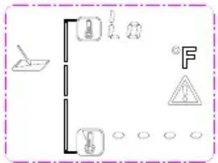
text_image
Diagram showing electrical circuit symbols including a lamp, fuse, capacitor, warning sign, and ground connectionsnatural_image
Pure electrical circuit lines without any symbols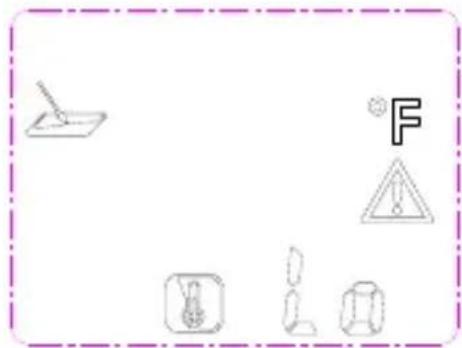
text_image
Diagram showing electrical hazard symbols including a fuse, warning triangle, and various electrical components with Chinese labels.Sistēmas klūda
text_image
Warning sign with warning triangle and cartoon objects, enclosed in a dashed border
text_image
Testboy GmbH, Germany Stands For Quality Since 1953Testboy GmbH Tel: 0049 (0)4441 / 89112-10
Germany info@testboy.de