
59G371 - Saw Graphite - Free user manual and instructions
Find the device manual for free 59G371 Graphite in PDF.
| Product type | Wall grooving saw (wall chaser) |
| Brand | Graphite |
| Model | 59G371 |
| Supply voltage | 230 V AC |
| Frequency | 50 Hz |
| Rated power | 2400 W |
| No-load speed | 8000 min⁻¹ |
| Disc diameter | 150 mm |
| Disc inner diameter | 22.2 mm |
| Max cutting depth | 43 mm |
| Groove width | 30 mm |
| Spindle thread size | M8 |
| Protection class | II (double insulation) |
| Weight | 6.1 kg |
| Production year | 2022 |
| Sound pressure level (LpA) | 97 dB(A) (K=3 dB(A)) |
| Sound power level (LwA) | 108 dB(A) (K=3 dB(A)) |
| Vibration (acceleration value) | 10.94 m/s² (K=1.5 m/s²) |
| Disc type | Combined diamond disc (multi-row) |
| Intended use | Making grooves in concrete, stone, brick (dry) |
| Main functions | Soft start, depth adjustment, dust extraction |
| Maintenance and cleaning | Clean with dry cloth or compressed air; replace carbon brushes (<5 mm) |
| Safety | Safety switch, overload protection, mandatory PPE |
| Included accessories | Combined disc, wrenches, hose with adapters, dust bag, clamp, carrying case |
Frequently Asked Questions - 59G371 Graphite
User questions about 59G371 Graphite
0 question about this device. Answer the ones you know or ask your own.
Ask a new question about this device
Download the instructions for your Saw in PDF format for free! Find your manual 59G371 - Graphite and take your electronic device back in hand. On this page are published all the documents necessary for the use of your device. 59G371 by Graphite.
USER MANUAL 59G371 Graphite
natural_image
Black GRACE power tool with coiled cable and handle, no visible text or symbols on the device itself10 ^* LAT
DOSTĘPNOŚCI
CZEŚCI ZAMIENNYCH
PL INSTRUKCJA ORYGINALNA (OBSŁUGI) 5
EN TRANSLATION (USER) MANUAL 8
natural_image
Close-up of hands operating a mechanical device with a tool, no visible text or symbols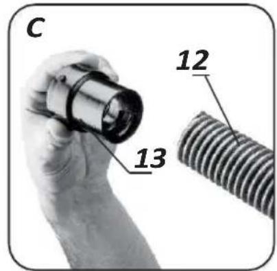
natural_image
Close-up of a hand holding a coiled metal pipe with a screwdriver above, no visible text or symbols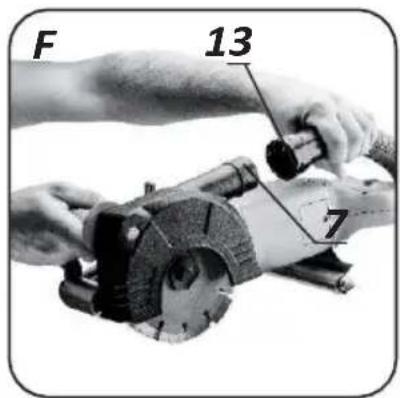
PL INSTRUKCJA ORYGINALNA (OBSŁUGI) BRUZDOWNICA 59G371
UWAGA: PRZED PRZYSTĄPIENIEM DO UŻYTKOWANIA ELEKTRONARZĘDZIA NALEŻY UWAŻNIE PRZECZYTAĆ NINIEJSZĄ INSTRUKCJĘ I ZACHOWAĆ JĄ DO DALSZEGO WYKORZYSTANIA.
SZCZEGÓŁOWE PRZEPISY BEZPIECZEŃSTWA
e-mail graphite@gtxservice.pl

TRANSLATION (USER) MANUAL
FURROWING MACHINE 59G371
NOTE: READ THIS MANUAL CAREFULLY BEFORE USING THE POWER TOOL AND KEEP IT FOR FUTURE REFERENCE.
SPECIFIC SAFETY PROVISIONS
Safety warnings for paving machines
- The power tool must only be used with the guard enclosed in the delivery. The guard must be securely attached to the power tool and adjusted to guarantee the greatest possible degree of safety, which means that the part of the cutting disc facing the operator
is to be shielded as much as possible. The guard is intended to protect the operator from debris and accidental contact with the cutting disc.
- Only diamond cutting discs should be used. The fact that an accessory can be attached to a power tool does not guarantee its safe use.
- The permissible speed of the working tool used must not be less than the maximum speed indicated on the power tool. A work tool rotating faster than the permissible speed may break and parts of the tool may splinter.
- Diamond cutting discs must only be used for the work intended for them. For example, never use the side surface of a cutting disc for grinding. Cutting discs are designed to remove material with the edge of the disc. The effect of lateral forces can cause the wheel of this type to break.
- Always use undamaged clamping flanges of the correct size for the selected cutting disc. The correct flanges support the cutting disc and thus reduce the risk of breakage.
- The outer diameter and thickness of the working tool must correspond to the dimensions of the power tool. Work tools with incorrect dimensions cannot be sufficiently shielded or inspected.
- Discs, washers, flanges and other accessories must fit exactly on the spindle of the power tool. Work tools that do not fit exactly on the spindle of the power tool will rotate unevenly, vibrate very strongly and may cause loss of control of the power tool.
- Under no circumstances should damaged working tools be used. Inspect work tools for chips and cracks before each use. If a power tool or work tool falls, check it for damage or use another undamaged work tool. Once the power tool has been checked and fixed, start the power tool and leave it running for one minute at the highest speed, taking care to keep the user and other bystanders out of the zone of the rotating power tool. Damaged tools usually break during this test.
- Personal protective equipment must be worn. Depending on the type of work, wear a protective mask covering the entire face, eye protection or safety goggles. If necessary, use a dust mask, hearing protection, protective gloves or a special apron to protect against small particles of abraded and machined material. Protect your eyes from airborne foreign bodies generated during work. A dust mask and respiratory protection must filter out dust generated during work. Exposure to noise over a prolonged period may lead to hearing loss.
- Ensure that bystanders are at a safe distance from the power tool's reach zone. Anyone in the vicinity of a working power tool must use personal protective equipment. Workpiece splinters or broken work tools can splinter and cause injury even outside the immediate reach zone.
- During work where a power tool could encounter
- on hidden electrical wires or on your own cord, hold it only by the insulated handle. On contact with live wires, all metal parts of the power tool will also be live and may cause an electric shock to the operator.
- Keep the mains cable away from rotating work tools. If you lose control of the tool, the mains cable could be cut or pulled in and your hand or whole hand could get caught in a rotating work tool.
- Never put the power tool down before the work tool has come to a complete stop. A rotating tool may come into contact with the surface on which it is put down, so you could lose control of the power tool.
- Do not carry a power tool while it is in motion. Accidental contact between clothing and a rotating power tool may cause the tool to be pulled in and drill the power tool into the operator's body.
- Clean the ventilation slots of the power tool regularly. The motor fan draws dust into the housing and a large accumulation of metal dust can cause an electrical hazard.
- Do not use the power tool near flammable materials. Sparks may ignite them.
- Do not use tools that require liquid coolants. The use of water or other liquid coolants can lead to electric shock.
Rejection and relevant safety tips
Kickback is the sudden reaction of a power tool to the blockage or obstruction of a rotating work tool. The snagging or blocking leads to a sudden stop of the rotating work tool. The uncontrolled power tool will thus be jerked in the direction opposite to the direction of rotation of the working tool.
When, for example, the grinding wheel becomes jammed or stuck in the workpiece, the immersed edge of the grinding wheel can become blocked and cause it to fall out or eject. The movement of the grinding wheel (towards or away from the operator) is then dependent on the direction of movement of the wheel at the point of blockage. In addition, grinding wheels can also break.
Recoil is a consequence of improper or incorrect use of the power tool. It can be avoided by taking the appropriate precautions described below.
- The power tool should be held firmly, with the body and hands in a position to soften the recoil. If an auxiliary handle is included as part of the standard equipment, it should always be used in order to have as much control as possible over the recoil forces or the recoil moment at start-up. The operator can control the jerk and recoil phenomena by taking appropriate precautions.
- Never hold hands near rotating work tools. The working tool may injure your hand due to recoil.
- Keep away from the range zone where the power tool will move during recoil. As a result of recoil, the power tool moves in the opposite direction to the movement of the grinding wheel at the point of blockage.
- Be particularly careful when machining corners, sharp edges, etc. Prevent work tools from being deflected or becoming jammed. A rotating work tool is more susceptible to jamming when machining angles, sharp edges or if it is kicked back. This can become a cause of loss of control or kickback.
- Do not use wood discs, diamond segment discs with a peripheral gap of more than 10 mm or toothed discs. Work tools of this type often cause recoil or loss of control of the power tool.
- Avoid jamming of the cutting disc or too much pressure. Do not make excessively deep cuts. Overloading the cutting disc increases the load on the blade and its tendency to jam or block and thus the possibility of discarding or breaking.
- If the cutting disc becomes jammed or if there is an interruption in operation, switch off the power tool and wait until the disc has fully
- will stop. Never attempt to pull the still moving disc out of the cutting area as this may cause recoil. The cause of the jamming must be detected and removed.
- Do not restart the power tool while it is in the material. The cutting wheel should reach its full speed before continuing to cut. Otherwise, the grinding wheel may catch, jump off the workpiece or cause recoil.
- Plates or large objects should be supported before machining to reduce the risk of kickback caused by a jammed disc. Large workpieces may bend under their own weight. The workpiece should be supported on both sides, both near the cutting line and at the edge.
- Take special care when cutting holes in walls or operating in other invisible areas. The cutting disc plunging into the material may cause the tool to recoil if it encounters gas pipes, water pipes, electrical cables or other objects.
NOTE: The device is for indoor use
Despite the use of an inherently safe design, the use of safety measures and additional protective measures, there is always a residual risk of injury during work.
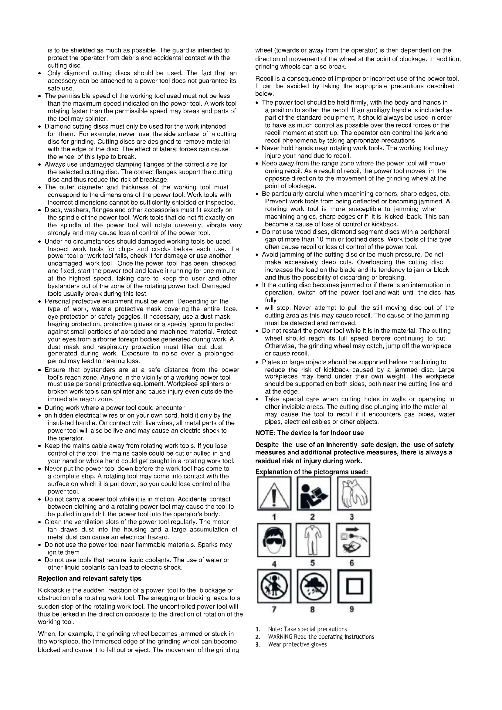
Explanation of the pictograms used:

- Note: Take special precautions
- WARNING Read the operating instructions
-
Wear protective gloves
-
Wear personal protective equipment (dust mask, safety goggles, ear protection)
-
Use protective clothing
- Unplug the power cord before servicing or repair work
- Keep children away from the tool
- Protect the device from moisture
- Second class of protection
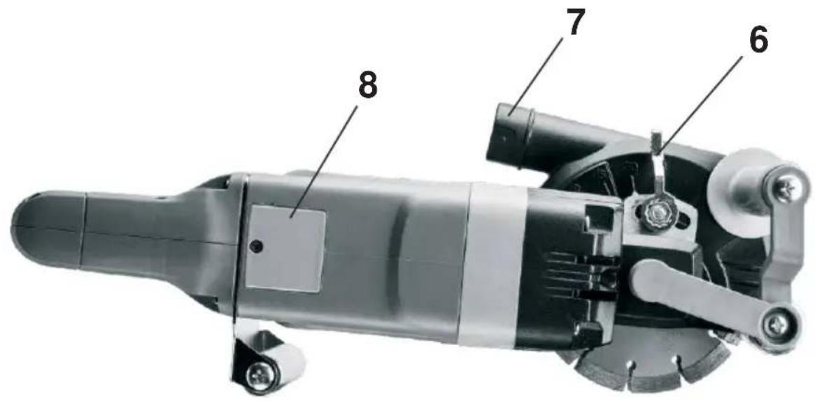
DESCRIPTION OF THE GRAPHIC PAGES
The numbering below refers to the components of the unknown on the graphic pages of this manual.
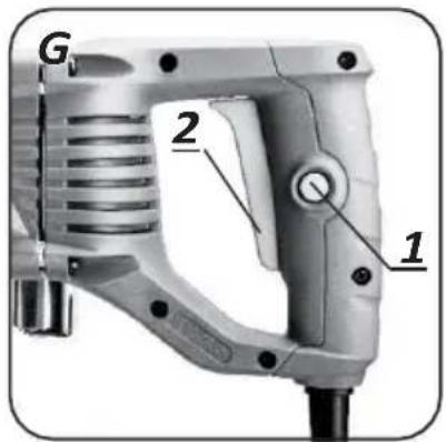
- Switch lock button
- Switch
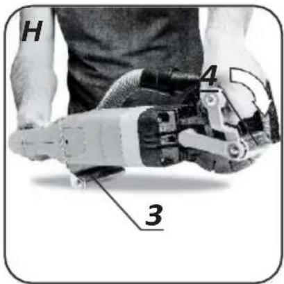
- Rear guide roller
- Front guide roller
- Fronthandle
- Lockinglever
- Dust discharge nozzle
- Carbon brush cover
- Clamping screw
- External flange
- Spindle flange
- Hose
- Adapter
- Dust bag
- Buckle
- Drainage opening
- Inletopening
- Shoulder strap
There may be differences between the drawing and the product.
CONSTRUCTION AND APPLICATION
The furrowing machine is a hand-held power tool driven by a single-phase commutator motor with Class II insulation.
The power tool is designed for making installation furrows in walls, etc. in materials such as concrete, stone, brick, etc., without using water.
The design of the furrowing machine allows the dust to be ejected into the enclosed bag or to be extracted by an industrial hoover. The special disc used cuts a full furrow without the need for chipping. As a result, the groove is ready for installation at the set depth.
Its areas of use are the execution of renovation and construction work related to electrical, plumbing, heating or gas installation.
The appliance is designed for dry running only. Do not misuse the power tool.
EQUIPMENT AND ACCESSORIES
- Combinationdisc - 1 pc.
- Key - 2 pcs.
- Hose with adapters - 1 pc.
- Dust bag - 1 pc.
- Clamp - 1 pc.
- Transportcase - 1 pc.
PREPARATION FOR WORK
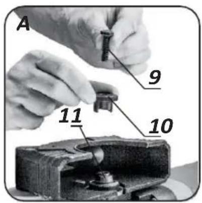
SHIELD MOUNTING
The paving machine is designed to work with dedicated multi-row compound discs.
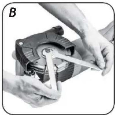
- Use the supplied spanners to lock the spindle by holding the outer flange (10) and unscrew the fastening screw.
• (9) (Fig. A, B). The fixing screw has a left-hand thread. - Remove the retaining screw (9) and remove the outer flange (10) (fig. A).
- Slide the disc under the guard and place the disc on the spindle.
- A well seated disc must rest on the spindle flange
- (Fig. A). The spindle will not fill the full depth of the disc mounting hole.
- Slide the outer flange into the hole in the disc. Pressing down on the outer flange, turn it until it sinks into the hole so that it is in complete contact with the disc plate.
- Screw in the fixing screw.
- Using the spanners, lock the spindle and tighten the fixing screw (Fig. B).
Removal of the disc follows the reverse order of installation.
FITTING A DUST BAG
The furrowing machine comes with a dust bag with adjustable shoulder strap and hose adaptors to connect the dust bag to the furrowing machine.
- Unscrew one of the adapters (13) fitted to the ends of the hose
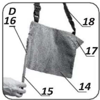
• (Fig. C). A left-hand thread was used there. - Open the dust bag (14) by sliding off the buckle (15) (fig. D).
- Through the emptying opening (16) of the dust bag, insert the previously dismantled adapter into the inlet opening (17) (fig. D) so that the narrowed section of the adapter slides partially outwards.
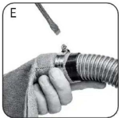
- Apply and clamp a metal clamp at the connection point of the adapter to the dust bag and connect the hose to the adapter (fig. E).
- Put the free end of the hose with the adapter (13) on the spigot
- dust outlet (7) (fig. F) and turn clockwise until it locks into place.
- Adjust the length of the shoulder strap (18) to ensure comfortable use with the dust bag (14) (fig. D).
Disassembly proceeds in reverse order to assembly.
DUST EXTRACTION CONNECTION
For a cleaner work area, the paving machine can be connected to an external dust extraction device.
Connect the suction hose end of the dust extraction system to the dust extraction port (7). Take care to select an adaptor with the correct diameter so that the connection is secure.
When starting work, start the dust extraction system, e.g. with an industrial hoover, and then switch off the paving machine. When you have finished work, switch off the paving machine first and then the hoover. This will avoid unnecessary dust in the workplace. On some models of industrial hoovers with a power socket for power tools, there is automatic switching on and off of the hoover controlled by the power tool switch.
SETTING THE FURROW DEPTH
Adjusting the furrow depth should be done before starting work with the machine switched off.
- Loosen the locking lever (6) by sliding it backwards.
- Move the front handle (5) backwards to increase the depth of cut, forward to decrease.
- A depth indicator and a scale located on the dial housing can help to set the correct depth.
- Once the correct depth has been set, tighten the locking lever (6) by moving it forwards.
Check the condition of the disc before using the power tool. Do not use chipped, cracked or otherwise damaged discs. A worn disc should be replaced immediately with a new one before use. When you have finished working, always switch off the power tool and wait until the working tool has come to a complete stop. Only then can the power tool be put away.
- The cutting disc must be fitted correctly and must rotate freely.
- Never overload the furrowing machine. Overloading and over-tightening can cause the cutting discs to break dangerously.
- Never strike the work tool against the work material.
- Never use saw blades designed for cutting wood from circular saws. The use of such saw blades often results in a recoil phenomenon of the power tool, loss of control and can lead to injury to the operator.
ON/OFF
The mains voltage must correspond to the voltage rating on the power tool's rating plate. Hold the power tool with both hands during start-up and operation.
The paving machine has a safety switch to prevent accidental start-up.
- Press the switch lock button (1) (Fig. C).
- Press the on/off button (2) (Fig. C).
- Releasing pressure on the switch button (2) stops the furrowing machine.
WORKING WITH A PAVING MACHINE
The paving machine is designed exclusively for making straight cuts. It is not permitted to make curved or rounded cuts. The machine is designed for dry operation only.
Before starting work, the site where work will be carried out should be examined for invisible water, electrical or gas installations, which should be located using a special cable finder.
The paving machine is equipped with a soft start system. After starting the paving machine, wait until the disc reaches maximum speed before starting work. The switch must not be operated while the paving machine is switched on or off. The switch on the pavers may only be operated when the power tool is away from the workpiece.
CUTTING A FURROW
- Set the depth of cut.
- Place the rear guide roller (3) against the wall (cutting discs raised above the wall surface) (Fig. H).
- Start the paving machine and wait for the cutting discs to reach full speed.
- Gradually lower the paving machine by plunging the cutting discs into the masonry (during this movement, the rear guide roller should make contact with the surface of the masonry).
- When the front guide roller (4) comes to rest on the masonry continue cutting by moving the paving machine in a forward direction away from you (against the direction of rotation of the cutting discs).
- Complete the cutting process in the reverse way of starting it by lifting the front guide roller and thus the disc upwards. The rear guide roller must be pressed against the wall at all times.
- Allow the disc to come to a complete stop after switching off and only then can the paving machine be put down.
- The furrow thus made is a fully hollow space and no longer requires chiselling.
When the paving machine is switched off, do not brake the rotating cutting disc by pressing it against the workpiece.
The paving machine must not be pressed too hard and pushed forward with force. The recessing pressure and the feed should be moderate. Exerting excessive force may cause excessive heating of the motor and damage to the cutting disc.
Cutting discs reach very high temperatures during operation - do not touch them with unprotected parts of the body before they have cooled down.
When cutting particularly hard materials, the cutting disc may overheat and thus be damaged. A sheaf of sparks surrounding the cutting disc is a symptom of overheating. Stop cutting immediately and cool the cutting disc by allowing the paving machine to run at maximum speed but without load for 3-5 minutes.
A visibly decreasing cutting performance and a sheaf of sparks surrounding the cutting disc can be a sign of a dulled cutting disc.
Use only working tools whose permissible speed is higher than or equal to the maximum speed of the paving machine without load.
Unplug the power cord from the mains socket before carrying out any installation, adjustment, repair or operation.
MAINTENANCE AND STORAGE
- It is recommended to clean the device immediately after each use.
- Do not use water or other liquids for cleaning.
- The unit should be cleaned with a dry piece of cloth or blown with low-pressure compressed air.
- Do not use any cleaning agents or solvents, as these may damage the plastic parts.
- Clean the ventilation slots in the motor housing regularly to prevent the unit from overheating.
- If the power cable is damaged, it must be replaced with a cable of the same characteristics. This operation should be entrusted to a qualified specialist or have the appliance serviced.
-
If excessive sparking occurs on the commutator, have the condition of the motor's carbon brushes checked by a qualified person.
-
Always store the device in a dry place out of the reach of children.
• REPLACEMENT OF CARBON BRUSHES - Worn (shorter than 5 mm), burnt or cracked motor carbon brushes must be replaced immediately. Always replace both carbon brushes at the same time.
• Unscrew and remove the carbon brush covers ( 8). - Pull back the pressure spring, disengage and remove the worn carbon brushes.
- Remove any carbon dust, if any, using compressed air.
- Fit the new carbon brushes (the brushes should slide freely into the brush holders) and the compression spring into place.
• Fit the carbon brush covers ( 8).
After replacing the carbon brushes, start the power tool without a load and wait 1-2 minutes until the carbon brushes fit into the motor commutator. Only a qualified person should replace the carbon brushes using original parts.
Any defects should be rectified by the manufacturer's authorised service department.
TECHNICAL SPECIFICATIONS
RATING DATA
| Chasing block 59G371 | |
| Parameter | Value |
| Supply voltage | 230 V AC |
| Supplyfrequency | 50 Hz |
| Rated power | 2400 W |
| Idle speed | 8000 min-1 |
| Disc diameter | 150 mm |
| Internal disc diameter | 22.2 mm |
| Max. cutting depth | 43 mm |
| Furrow width | 30 mm |
| Spindle thread size | M8 |
| Protection class | II |
| Mass | 6.1 kg |
| Year of production | 2022 |
| 59G371 stands for both type and machine designation | |
NOISE AND VIBRATION DATA
Information on noise and vibration
Emitted noise levels, such as the level of pressure emitted
The sound power level LpA and the sound power level LwA, as well as the measurement uncertainty K_i are given below in accordance with EN 60745-1. The vibration values (acceleration value) ah and the measurement uncertainty K are given below in accordance with EN 60745-2-22.
The vibration level given below in these instructions has been measured in accordance with the measurement procedure specified by EN 60745-1 procedure and can be used to compare power tools. It can also be used for initial assessment of vibration exposure.
The vibration level indicated is representative of the basic use of the power tool. If the power tool is used for other applications or with other work tools, and if it is not sufficiently maintained, the vibration level may change. The reasons given above may result in increased vibration exposure throughout the working period.
To accurately estimate vibration exposure, it is necessary to take into account periods when the power tool is switched off or when it is switched on but not used for work. In this way, the total exposure to vibration may turn out to be much lower.
Additional safety measures should be put in place to protect the user from the effects of vibration, such as: maintenance of the power tool and working tools, securing an appropriate hand temperature, proper work organisation.
Sound pressure level LpA = 97 dB(A) K=3dB(A) Sound power level LwA = 108 dB(A) K=3dB(A) Vibration acceleration value ah = 10.94 m/s2 K=1.5 m/s2
ENVIRONMENTAL PROTECTION
* Subject to change.
Electrically powered products should not be disposed of with household waste, but should be disposed of in appropriate facilities. Information disposal is provided by the dealer of the product or local authorities. Waste electrical and electronic equipment contains substances that are not neutral for the natural environment. Non recycled equipment is a potential threat to the environment and human health..
"Grupa Topex Spółka z ograniczoną odpowiedzialnością" Spółka komandytowa with its registered office in Warsaw, ul.Pograniczna 2/4 (hereinafter: "Grupa Topex") informs that all copyrights to the content of this manual (hereinafter: "Manual"), including, among others. Its text, photographs, diagrams, drawings, as well as its composition, belong exclusively to Grupa Topex and are subject to legal protection under the Act of 4 February 1994 on Copyright and Related Rights (Journal of Laws 2006 No. 90 Poz. 631, as amended). Copying, processing, publishing, modification for commercial purposes of the entire Manual antis individual elements, without the consent of Grupa Topex expressed in writing, is strictly prohibited and may result in civil and criminal liability.
EC Declaration of Conformity
Manufacturer: Grupa Topex Sp. z o.o. Sp.k., Pograniczna 2/4 02-285
Warszawa
Product: Paving machine
Model: 59G371
Trade name: GRAPHITE
Serial number: 00001 ÷ 99999
This declaration of conformity is issued under the sole responsibility of the manufacturer.
The product described above complies with the following documents:
Machinery Directive 2006/42/EC
Electromagnetic Compatibility Directive 2014/30/EU
RoHS Directive 2011/65/EU as amended by Directive 2015/863/EU
And meets the requirements of the standards:
EN 60745-1:2009+A11:2010; EN 60745-2-22:2011+A11:2013
EN 55014-1:2017+A11:2020; EN 55014-2:2015;
EN IEC 61000-3-2:2019; EN 61000-3-3:2013+A1:2019; EN IEC 61000-3-11:2019;
EN IEC 63000:2018
This declaration relates only to the machinery as placed on the market and does not include components
added by the end user or carried out by him/her subsequently.
Name and address of the EU resident person authorised to prepare the technical dossier:
Signed on behalf of:
Grupa Topex Sp. z o.o. Sp.k.
TOPEX GROUP Quality Officer
Warsaw, 2022-03-17
DONNÉES D'ÉVALUATION


- PL INSTRUKCJA ORYGINALNA (OBSŁUGI) BRUZDOWNICA 59G371
- SZCZEGÓŁOWE PRZEPISY BEZPIECZEŃSTWA
- TRANSLATION (USER) MANUAL
- FURROWING MACHINE 59G371
- NOTE: READ THIS MANUAL CAREFULLY BEFORE USING THE POWER TOOL AND KEEP IT FOR FUTURE REFERENCE.
- SPECIFIC SAFETY PROVISIONS
- Safety warnings for paving machines
- Rejection and relevant safety tips
- NOTE: The device is for indoor use
- DESCRIPTION OF THE GRAPHIC PAGES
- CONSTRUCTION AND APPLICATION
- The appliance is designed for dry running only. Do not misuse the power tool.
- EQUIPMENT AND ACCESSORIES
- PREPARATION FOR WORK
- SHIELD MOUNTING
- FITTING A DUST BAG
- DUST EXTRACTION CONNECTION
- SETTING THE FURROW DEPTH
- ON/OFF
- WORKING WITH A PAVING MACHINE
- CUTTING A FURROW
- MAINTENANCE AND STORAGE
- TECHNICAL SPECIFICATIONS
- NOISE AND VIBRATION DATA
- Information on noise and vibration
- ENVIRONMENTAL PROTECTION
- EC Declaration of Conformity
- Machinery Directive 2006/42/EC
- Electromagnetic Compatibility Directive 2014/30/EU
- EN IEC 63000:2018
Brand : Graphite
Model : 59G371
Category : Saw