
H-SB 801 E - Drill Herkules - Free user manual and instructions
Find the device manual for free H-SB 801 E Herkules in PDF.
| Product type | Drill press |
| Brand | Herkules |
| Model | H-SB 801 E |
| Power supply | 230 V ~ 50 Hz |
| Rated power | 550 W |
| Motor speed | 1400 rpm |
| Speed range (starting speed) | 450 - 2500 rpm (steplessly adjustable) |
| Distance from spindle axis to frame | 160 mm |
| Maximum drilling depth | 80 mm |
| Chuck capacity | 1.5 - 16 mm (keyed three-jaw chuck) |
| Drill spindle taper | MK2 |
| Chuck mounting taper | B16 |
| Column diameter | 65 mm |
| Drilling table dimensions | 240 x 240 mm |
| Table tilt | 45°/0°/45° |
| Machine height | 940 mm |
| Footprint (base) | 450 x 300 mm |
| Net weight | 43 kg |
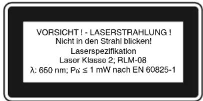
| Laser class | 2 |
| Laser wavelength | 650 nm |
| Laser power | ≤ 1 mW |
| Sound pressure level (idle) | 69.2 dB(A) |
| Sound power level (idle) | 78.6 dB(A) |
| Supplied accessories | Drill chuck, chip guard, depth stop, chuck key, crank, handles, laser guide |
Frequently Asked Questions - H-SB 801 E Herkules
User questions about H-SB 801 E Herkules
0 question about this device. Answer the ones you know or ask your own.
Ask a new question about this device
Download the instructions for your Drill in PDF format for free! Find your manual H-SB 801 E - Herkules and take your electronic device back in hand. On this page are published all the documents necessary for the use of your device. H-SB 801 E by Herkules.
USER MANUAL H-SB 801 E Herkules
GBR Original operating instructions Pillar Drill
HUN Eredeti hasznalatiutasitas Oszlopos furogep
- Safety regulations
- Layout and items supplied
- Proper use
- Technical data
- Before starting the equipment
- Operation
- Replacing the power cable
- Cleaning, maintenance and ordering of spare parts
- Disposal and recycling
GBR

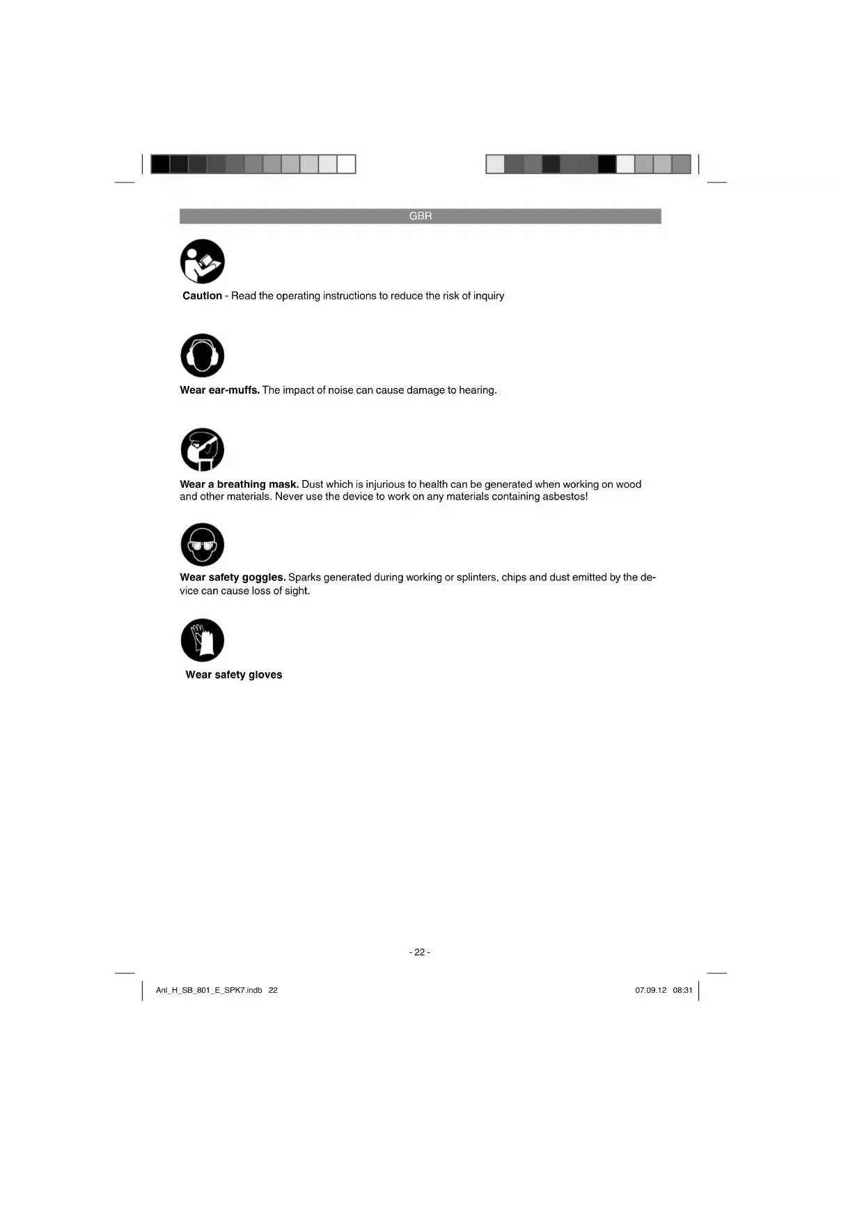
Caution - Read the operating instructions to reduce the risk of inquiry

Wear ear-muffs. The impact of noise can cause damage to hearing.

Wear a breathing mask. Dust which is injurious to health can be generated when working on wood and other materials. Never use the device to work on any materials containing asbestos!

Wear safety goggles. Sparks generated during working or splinters, chips and dust emitted by the device can cause loss of sight.

Wear safety gloves
GBR
Important!
When using the equipment, a few safety precautions must be observed to avoid injuries and damage. Please read the complete operating instructions and safety regulations with due care. Keep this manual in a safe place, so that the information is available at all times. If you give the equipment to any other person, hand over these operating instructions and safety regulations as well. We cannot accept any liability for damage or accidents which arise due to a failure to follow these instructions and the safety instructions.
1. Safety regulations
The corresponding safety information can be found in the enclosed booklet.
Caution!
Read all safety regulations and Instructions. Any errors made in following the safety regulations and instructions may result in an electric shock, fire and/or serious injury. Keep all safety regulations and instructions in a safe place for future use.
1.1 Special instructions for the laser

portant: Laser radiation, but look into the beam in class 2
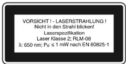
- Never look directly into the laser path.
- Never direct the laser beam at reflecting surfaces or persons or animals. Even a low output laser beam can inflict injury on the eye.
- Caution: It is vital to follow the work procedures described in these instructions. Using the equipment in any other way may result in hazardous exposure to laser radiation.
-
Never open laser module.
-
When the pillar drill is not going to be used for an extended period of time, the batteries should be removed. It is prohibited to carry out any modifications to the laser to increase its power.
- Do not make any modifications to the laser that are designed to increase the laser's power.
The manufacturer cannot accept any liability for damaged caused by a failure to comply with the safety information.
2. Layout and items supplied
2.1 Layout (Fig. 1)
- Machine base
- Pillar
- Roller support
- Drill table
- Drill table clamp shaft
- Machine head
- V-belt
8.Motor - Grip knobs
- Drill chuck
- Spindle
- Mounting holes
- Folding chip guard
- Depth stop
- Speed control lever
- Screw
- Digital display
- ON switch
- OFF switch
- ON/OFF switch (laser)
- Drill chuck
GBR
2.2 Items supplied
Please check that the article is complete as spcified in the scope of delivery. If parts are missing, please contact our service center or the nearest branch of the DIY store where you made your purchase at the latest within 5 work days after purchasing the article and upon presentation of a valid bill of purchase. Also, refer to the warranty table in the warranty provisions at the end of the operating instructions.
- Open the packaging and take out the equipment with care.
- Remove the packaging material and any packaging and/or transportation braces (if available).
Check to see if all items are supplied.
Inspect the equipment and accessories for transport damage.
If possible, please keep the packaging until the end of the guarantee period.
Important!
The equipment and packaging material are not toys. Do not let children play with plastic bags, folls or small parts. There is a danger of swallowing or suffocating!
Original operating instructions
- Safetyinstructions
Pillardrill
Drill chuck
- Folding chip guard
- Stop
3. Proper use
This pillar drill is designed for drilling metal, plastic, wood and similar materials. It is intended for use in the private sector only.
Food and harmful materials may not be processed with the machine. The drill chuck is only designed for use with drill bits and tools with a shaft diameter of 1,5 to 16mm and for cylindrical tool shanks. Tools with a tapered shank can also be used. The machine is intended for use by adults only.
The equipment is to be used only for its prescribed purpose. Any other use is deemed to be a case of misuse. The user / operator and not the manufacturer will be liable for any damage or injuries of any kind caused as a result of this.
Please note that our equipment has not been designed for use in commercial, trade or industrial applications. Our warranty will be voided if the machine is used in commercial, trade or industrial businesses or for equivalent purposes.
4. Technical data
Nominal input voltage 230V \~ 50 Hz
Power rating 550 W
Motor speed. 1,400 rpm
Output speed (infinitely adjustable) 450-2,500 rpm
Drill chuck mount B 16
Spindle taper . MK 2
Scroll chuck . 01,5-16 mm
Reach 160 mm
Dimensions of drill table. 240× 240mm
Angle adjustment of table 45^ / 0^ / 45^
Drill depth 80 mm
6 Pillar diameter 65 mm
Height 940mm
Base area 450 x 300 mm
Weight. 43 kg
Laser class. 2
Wavelength of laser 650 nm
Laser output. 1 mW
Sound and vibration
Sound and vibration values were measured in accordance with EN 60745.
Operation
Idle speed
Sound pressure level Lp_A
69.2 dB(A)
65.5 dB(A)
Sound power level LW_A 78.6 dB(A) 76.4 dB(A)
Wear ear-muff s.
The impact of noise can cause damage to hearing.
Total vibration values (vector sum of three directions) determined in accordance with EN 61029.
Handle
Vibration emission value a_s ≤ 2.5m / s^2
K uncertainty = 1.5m / s^2
GBR
Warning!
The specified vibration value was established in accordance with a standardized testing method. It may change according to how the electric equipment is used and may exceed the specified value in exceptional circumstances.
The specified vibration value can be used to compare the equipment with other electric power tools.
The specified vibration value can be used for initial assessment of a harmful effect.
Keep the noise emissions and vibrations to a minimum.
Only use appliances which are in perfect working order.
Service and clean the appliance regularly.
Adapt your working style to suit the appliance.
Do not overload the appliance.
- Have the appliance serviced whenever necessary.
- Switch the appliance off when it is not in use.
Wear protective gloves.
Residual risks
Even if you use this electric power tool in accordance with instructions, certain residual risks cannot be rules out. The following hazards may arise in connection with the equipment's construction and layout:
- Lung damage if no suitable protective dust mask is used.
- Damage to hearing if no suitable ear protection is used.
- Health damage caused by hand-arm vibrations if the equipment is used over a prolonged period or is not properly guided and maintained.
5. Before starting the equipment
5.1.Installing the machine
- Place the base plate (1) in the desired position.
- Fasten the pillar (2) with flange using the supplied bolts (A) (Figs. 3 - 4).
- You can now fit the table and clamp in place with the clamping lever. Following this, fit the crank (27) and fasten tightly with the screw (28). (Fig. 5-7)
Finally, fit the complete bit head to the pillar. Align the head so that it is horizontal to the base plate and fasten it in position with the screws (35). (Fig. 8-9)
- Screw the 3 supplied handles (9) in the handle mounts. (Fig. 10).
Screw in the speed control lever (15) as shown in Figure 11.
- Secure the roller support (3) with thumb screws (21) (Fig. 12).
Before you mount the drill chuck with the MK shank, check that both parts are clean. Insert the taper mandrel in the taper of the drill chuck with a powerful jolt. Then insert the taper in the spindle. To do this, place the drill chuck (10) with taper (24) in the spindle (11) and guide it to the stop point, then turn the chuck until it slips a little further into the spindle (11). Insert the drill chuck (10) with taper (24) into the spindle (11) with a jolt and check that the chuck is secure (Figs. 13-14).
Important: All bare parts are greased in order to protect them from corrosion. Before mounting the drill chuck (10) onto the spindle (11), both parts must be completely degreased using an environmentally friendly solvent. This ensures optimal transmission of power.
5.2. Installing the machine
Before you use the drill for the first time it must be mounted in a stationary position on a firm surface. Use both mounting holes (12) in the base plate to do this. Ensure that the machine is freely accessible for operation, adjustment and maintenance. Important: The fi xing screws may only be tightened to a point where they do not distort or deform the base plate. Excessive tension can lead to fracture.
5.3.Folding chip guard (Figs.15-17)
Mount the folding chip guard (13) as shown in Figures 15 and 16.
The height of the cover (23) is infinitely adjustable and can be locked using both thumb screws (22). The chip guard (13) can be flipped up to enable bits to be changed.
5.4. Prior to starting
Ensure that the voltage of the mains supply complies with the specific cations on the rating plate. Connect the machine only to a socket with the properly installed earthing contact.
The table drill is equipped with a no-volt trip that is designed to protect the operator from an undesi
GBR
red restart following a drop in voltage. Should this occur, the machine must be manually restarted.
6. Operation
6.1. General (Fig. 18)
To switch on the machine, push in the green On button "I" (18); the machine starts up. To switch off, press the red Off button "O" (19); the device shuts down.
Ensure that you do not overload the device. If the sound of the motor drops in pitch during operation, it is being overloaded. Do not overload the device to the point where the motor comes to a standstill. Always stand in front of the machine during operation.
6.2. Inserting the tool (Fig. 1)
Make sure that the power plug is removed from the socket-outlet before changing tools. Only cylindrical tools with the stipulated maximum shaft diameter may be clamped in the scroll chuck (10). Only use a tool that is sharp and free of defects. Do not use tools whose shaft is damaged or which are deformed or flawed in any other way. Use only accessories and attachments that are specified in the operating instructions or have been approved by the manufacturer. If the pillar drill should become jammed, switch off the machine and return the drill to its starting position.
6.3. Handling the keyless chuck
Your pillar drill is equipped with a keyless chuck. This enables tools to be changed without the need for an additional chuck key. To do so, insert the tool in the quick-change drill chuck and tighten by hand.
6.4 Using tools with tapered shanks (Fig. 19)
The pillar drill comes with a spindle taper. To use tools with tapered shanks (MK2), proceed as follows:
- Move the drill chuck to the lower position.
- Lock the spindle in the lowered position using the bottom scale ring (25) to maximize access to the drill chuck (see point 7.6).
- Eject the tapered shank using the supplied drill drift (31), taking care as you do so to ensure that the tool does not land on the floor.
- Insert the new tool with tapered shank in the spindle taper with a jolt and then check that the tool is correctly seated.
6.5. Setting the speed (Fig. 1)
The operating speed of the machine is infinitely adjustable.
Important!
Speed adjustments are allowed only when the motor is running.
Slowly and steadily move the speed control lever (15) while the machine is in idle mode.
- Ensure that the machine can run without Interruption (i.e. remove workpieces, drill bits, etc.).
Use the speed control lever (15) to infinitely adjust the speed. The set speed is shown on the digital display (17) in revolutions per minute.
Important! Never let the pillar drill run when the V-belt cover is open. Always pull power plug before opening the cover. Never touch the V-belt when it is rotating.
6.6 Drill depth stop (Fig. 20/Item 14)
The drilling spindle has a swivelling scale ring for setting the drill depth. Only adjust the setting when the machine is at a standstill.
Press the drilling spindle (11) downwards until the tip of the drill bit touches the workpiece.
- Turn the scale ring (25) all the way down.
- Turn the scale ring (25) up by the distance of the desired drill depth and lock the setting with the second scale ring (25).
The highest setting of the drilling spindle can likewise be adjusted using the bottom scale ring (practical when ejecting the drill chuck see point 7.4).
6.7.Setting the angle of the drill table (Fig. 21-22)
- Slacken the carriage bolt (26) under the drill table (4).
Set the drill table (4) to the desired angle. - Tighten down the carriage bolt (26) in order to lock the drill table (4) into this position.
6.8. Setting the height of the drill table (Fig. 21; 23)
Slacken the tightening screw (37).
- Set the drill table to the desired position with the help of the hand crank (27).
- Screw the tightening screw (37) back down again.
GBR
6.9 Drill table and roll base (Fig. 24)
Slacken the clamping screw (29) to turn the drill table (4).
- Slacken the thumb screws (21) to extend the roll base (3).
6.10 Clamping the workpiece (Fig. 25)
As a general rule, use a machine vice or another suitable clamping device to secure a workpiece in position. Never hold the workpiece in place with your hand! When drilling, the workpiece should be able to travel on the drill table (4) for self-centering purposes. Ensure that the workpiece cannot rotate. This is best achieved by placing the workpiece /machine vice on a sturdy block. Caution! Sheet metal parts must be clamped in to prevent them from being torn up. Properly set the height and angle of the drill table for each workpiece. There must be enough distance between the upper edge of the workpiece and the tip of the drill bit.
This machine is fitted with an adjustable stop (30). Proceed as follows to position it:
- Move the sliders on the stop (30) into two of the four guide slots in the drill table (4).
Set the stop (30) to the desired position. - Fasten the stop (30) to the drill table using both spindle screws (32).
Now slacken the thumb screw (33) on the angle piece (34) and position the angle piece (34) such that the workpiece can be placed against the stop (30) and the angle piece (34).
Note: The drill speeds specified are merely suggested values.
| Drill bit Ø | Cast Iron | Steel | Iron | Aluminum | Bronze |
| 3 | 2550 | 1600 | 2230 | 9500 | |
| 4 | 1900 | 1200 | 1680 | 7200 | 6000 |
| 5 | 1530 | 955 | 1340 | 5700 | 4800 |
| 6 | 1270 | 800 | 1100 | 4800 | 4000 |
| 7 | 1090 | 680 | 960 | 4100 | 3400 |
| 8 | 960 | 600 | 840 | 3600 | 3000 |
| 9 | 850 | 530 | 740 | 3200 | 2650 |
| 10 | 765 | 480 | 670 | 2860 | 2400 |
| 11 | 700 | 435 | 610 | 2600 | 2170 |
| 12 | 640 | 400 | 560 | 2400 | 2000 |
| 13 | 590 | 370 | 515 | 2200 | 1840 |
| 14 | 545 | 340 | 480 | 2000 | 1700 |
| 16 | 480 | 300 | 420 | 1800 | 1500 |
| 18 | 425 | 265 | 370 | 1600 | 1300 |
| 20 | 380 | 240 | 335 | 1400 | 1200 |
| 22 | 350 | 220 | 305 | 1300 | 1100 |
| 25 | 305 | 190 | 270 | 1150 | 950 |
6.13 Countersinking and center-drilling
With this table drill, you can also countersink and center-drill. Please observe that countersinking should be performed at the lowest speed, while a high speed is required for center-drilling.
6.14 Drilling wood
Please note that sawdust must be properly evacuated when working with wood, as it can pose a health hazard. Ensure that you wear a suitable dust mask when performing work that generates dust.
6.11 Using the laser (Fig. 11; 18/Item 36)
To switch on: Move the ON/OFF switch (20) to the "I" position to switch on the laser. Two laser lines are projected on the workpiece and intersect at the center of the drill tip contact point. To switch off: Move the ON/OFF switch (20) to the "O" position.
Setting the laser: Slacken the screws (41) to adjust the laser. Retighten the screws after you have made the adjustment. Important! Never look directly into the laser beam!
6.12 Working speeds
Ensure that you drill at the proper speed. Drill speed is dependent on the diameter of the drill bit and the material in question.
The table below acts as a guide for selecting the proper speed for various materials.
GBR
7. Replacing the power cable
If the power cable for this equipment is damaged, it must be replaced by the manufacturer or its after-sales service or similarly trained personnel to avoid danger.
8. Cleaning, maintenance and ordering of spare parts
Warning!
Pull out the power plug before carrying out any adjustments, maintenance or repairs.
8.1 Cleaning
The table drill is to a large extent maintenance-free. Keep the device clean. Pull out the mains plug before doing any cleaning and maintenance work on the machine. Do not use any harsh, abrasive cleaning solvents. Ensure that no liquid seeps into the device. Regrease all bare parts when the work is finished. The drill pillar, blank parts of the column, and the drill table especially should be regressed at regular intervals. Use a standard, acid-free lubricating grease to do this. Caution: Do not use your household refuse bin as a receptacle for oil and grease-soaked cleaning rags or grease and oil sludge. Dispos of these toxic materials in an environmentally-friendly fashion. Regularly check and clean the ventilation holes. Store the device in a dry room. Should the device become damaged, do not try to repair it yourself; leave this work to the hands of a qualified electrical technician.
We recommend that you clean the device
immediately each time you have finished using it.
Clean the equipment regularly with a moist cloth and some soft soap. Do not use cleaning agents or solvents; these could attack the plastic parts of the equipment. Ensure that no water can seep into the device.
8.2 Maintenance
There are no parts inside the equipment which require additional maintenance.
8.2.1 Changing the V-belt (Figs. 26 - 28)
The V-belt of the pillar drill is a wear part and should be replaced when worn. Proceed as follows:
- Run the machine run in idle mode while slowly setting the speed adjustor lever (15) to the minimum speed (see point 7.5).
- Switch the machine off, then pull the power plug.
- Set the speed adjustor lever (15) to the maximum speed setting to slacken the
V-belt. - Undo the screw (16) to open the V-belt cover (7).
- Pry the V-belt (39) off of the drive pulley (38) by pulling up the belt on one side and slowly turning the pulley (38). The drive pulley (38) comprises two disks that are pressed together via a spring. If the V-belt (39) does not exhibit enough play to remove it, gently press the bottom half of the drive pulley (38) down to slacken the V-belt (39).
- Fit one end of the new V-belt (39) to the variable pulley (40). Fit the other end to the drive pulley (38) by first sliding it into the groove on one side of the pulley (38), then prying the V-belt (39) across the pulley into the groove on the other side.
- Close the V-belt cover and screw down using the screw (16).
8.3 Ordering replacement parts:
Please quote the following data when ordering replacement parts:
Type of machine
Article number of the machine
Identification number of the machine
- Replacement part number of the part required
For our latest prices and information please go to www.isc-gmbh.info
GBR
9. Disposal and recycling
The equipment is supplied in packaging to prevent it from being damaged in transit. The raw materials in this packaging can be reused or recycled. The equipment and its accessories are made of various types of material, such as metal and plastic. Never place defective equipment in your household refuse. The equipment should be taken to a suitable collection center for proper disposal. If you do not know the whereabouts of such a collection point, you should ask in your local council offices.
GBR

For EU countries only
Never place any electric power tools in your household refuse.
To comply with European Directive 2002/96/EC concerning old electric and electronic equipment and its implementation in national laws, old electric power tools have to be separated from other waste and disposed of in an environment-friendly fashion, e.g. by taking to a recycling depot.
Recycling alternative to the return request:
As an alternative to returning the equipment to the manufacturer, the owner of the electrical equipment must make sure that the equipment is properly disposed of if he no longer wants to keep the equipment. The old equipment can be returned to a suitable collection point that will dispose of the equipment in accordance with the national recycling and waste disposal regulations. This does not apply to any accessories or aids without electrical components supplied with the old equipment.
The reprinting or reproduction by any other means, in whole or in part, of documentation and papers accompanying products is permitted only with the express consent of the iSC GmbH.
Subject to technical changes
GBR
Warranty certificate
Dear Customer,
In the unlikely event that your device develops a fault, we are truly sorry for this, and suggest that you please contact our service department at the address shown on this guarantee card, or contact the nearest authorised DIY store. Please note the following terms, under which guarantee claims can be made:
- These guarantee terms cover additional guarantee rights and do not affect your statutory warranty rights. We do not charge you for this guarantee.
- Our guarantee only covers problems caused by material or manufacturing defects, and it is restricted to the rectification of these defects or replacement of the device. Please note that our devices have not been designed for use in commercial, trade or industrial applications. Consequently, the guarantee is invalidated if the equipment is used in commercial, trade or industrial applications or for other equivalent activities. The following are also excluded from our guarantee: compensation for transport damage, damage caused by failure to comply with the installation/assembly instructions or damage caused by unprofessional installation, failure to comply with the operating instructions (e.g. connection to the wrong mains voltage or current type), misuse or inappropriate use (such as overloading of the device or use of non-approved tools or accessories), failure to comply with the maintenance and safety regulations, ingress of foreign bodies into the device (e.g. sand, stones or dust), effects of force or external influences (e.g. damage caused by the device being dropped) and normal wear resulting from proper operation of the device. This applies in particular to rechargeable batteries for which we nevertheless issue a guarantee period of 12 months. The guarantee is rendered null and void if any attempt is made to tamper with the device.
- The guarantee is valid for a period of 5 years starting from the purchase date of the device. Guarantee claims should be submitted before the end of the guarantee period within two weeks of the defect being noticed. No guarantee claims will be accepted after the end of the guarantee period. The original guarantee period remains applicable to the device even if repairs are carried out or parts are replaced. In such cases, the work performed or parts fitted will not result in an extension of the guarantee period, and no new guarantee will become active for the work performed or parts fitted. This also applies when an on-site service is used.
- In order to assert your guarantee claim, please send your defective device postage-free to the address shown below. Please enclose either the original or a copy of your sales receipt or another dated proof of purchase. Please keep your sales receipt in a safe place, as it is your proof of purchase. It would help us if you could describe the nature of the problem in as much detail as possible. If the defect is covered by our guarantee then your device will either be repaired immediately and returned to you, or we will send you a new device.
Also refer to the restrictions of this warranty concerning wear parts/consumables and missing parts as set forth in the warranty conditions in these operating instructions.
FRA
Sommaire
Attention: rayon laser is the best regarded in the field of rayon wave, since laser 2
2.1 Taekislysing (myndir 1)
- Taekisfotur
- Sula
- Bennikeft i
- Borvelaboro
- Borvelaborhaldari
- Borvélaborðhaldari
- Reimarhlif
- Motor
- Styrihold
- Borpatróna
- Borvélaoxull
- Festing
- Stillanleg sponahlif
- Bordyptartakmarkari
- Stillihaldfang snuningshraa
- Skrufa
- Stafraenn skjár
- Gangsetningarrofi
- Adrepari
- Hofurofi leysis
- Sveif
2.2 Innihald
Vinsamlegast yfi rfiari hlutinn og athugio hvort allir hlutir fylgi meo sem taldir eru upp i notandaleiobeiningunum. Ef ahluti vantar verour a hafa samband innan 5 vinnudaga eftir kaup hlutarins og framleggja kvittun hja bjonustuaola eoa verslun sem taikoi var keypt i. Vinsamlegast athugio toflu affast i leiobeingunum varandi hluti sem eru abyrgoir.
Opniumbuöirmar og takiö takiö varlega ut ur umbudunum.
Fjarlaegio umboirnar og lasingar umbu/ taekis (ef slikt er til staar).
Athugio hvort aoallir hlutir fylgi me taekinu.
Yfirfari takiog aukahluti pess og athugio hvort ao flutningaskemmdir séu ao finna.
Geymiumbuöirnar ef haegt er par til aábyrgoartimabil hefur runnó ut.
ISL
Varuó!
Kandke kaltskindaid!
EST
Tahelepanu!
HocTe 3aunTHn pbhAbu
BGR
BHHMaHHe!
PnH3noJ3BaHeTo Ha ypeIte TpR6Ba ce cna3BaT HAnKo npedNa3HN MepKn, CbP3aHc n 6e3oNaChOCTTa, 3a Da CE npEDOTBpaTAT HapaHABHaN I eTt. 3a eLTA BHHMaTeHIO npOHTe TOBA yNbTBaHe 3a ynotpe6a/ yka3aHa 3a 6e3oNaChOCT. Na3e To dO6pe, 3a Da pa3noJaate C INHOpMaunrta NO BCKO bpeMe. B cnyau, He TpR6Ba Da npedaTe YpeDa HA dpTy Nlua, MOJI, npedeAte IM ToBA yNBtBAHe 3a yNotpe6a/Yka3aHnra 3a 6e3oNaChOCT. Hne He NoeMaME OTROBOPHOCT 3a 3IOnNoLyH NII UeTI, KOINT Bb3HKNBAT BCNECTBHe Ha HeCb6IIOdaBaHE To BA yNbTBaHe N Ha Yka3aHnHTA 3a 6e3oNaChOCT.
HnKora He IeIepaIte DnpEeTHO XoJa Ha na3epHnaIb4.
HnKora He HacooyBaIte Ia3epHnIbU bBypXpePfLeHTnpAunIOBbPxHOCTN,XopaIIINJKNBOTHN.IOpN Ia3epENbUcMNHIMaHaMoOHTOMeJa npuHnYbpeKdaHeHaOHHTe.
BHHMaHHe - aHO ce H3NbJIHrBaT dpyrnpa6OTn,pa3JIHcH NT NOCOeHHeTc TUK,TOBAMoKe da DObEe do OnaCha paDnaauOnHhaekCnlo3nA.
Hnkora He oTbapTe na3epnmoyn.
AHO KOIOHnHa TcBpeIIOBbHnMaMuaHnHe ce H3IOJ3BaNo-dBfIO BpMe,To6aTePmTe Tp6Ba Da Ce N3BaT. He e pa3peWeno da ce N3BpWbat npOMeHNo Ia3epa, 3a Da ce yBeJIuN M0UHOCCTHa NaIa3epa.
He pa3peuHc da ce 3bpuBat npOMeHn no Ia3epa,3a da ce yBeJIuN MoUHocTtHa Ia3epa.
Ipon3BODHTeJIrHeNoEmaOTROBOPHOCT 3aUeTl,KHOITb3HHBaTBCNECTBHe Hecb6HIOdaBaHEToHaYka3aHnTa3a 6e3oNaCHOCT.
2.ОпсанеHaуретаиобemHadoctabka
2.1 Onicanhe na ypeda (Hr. 1)
1.CToNkHaMaunHaTa
2. KonoHa
3. Polkoba onopa
4. Maca ha 6opmaunHaTa
5. Hocau Ha macata Ha 6opmaunHaTa
6. MaunnHa rnaBa
7. 3aunTeH Kanak Ha KInHOBnHnpeMbK
8.Диагал
9.Дрьхн
10. NaTPOHHM 3a CBpeIIO
11. WnHdEi
12. OtvBOpu 3a 3aKpenBaHe
13. Cbbaema 3aunTa 3a cTbprotHH
14. OrpaHnHTeJ 3a dbl6OuHa
15. Ioc3a perynnpahe Ha 06opoHTe
16. B0I
17.ДиrtanenDnncnei
18. BhInouyBaTei
19.нанкювaten
20. BhIOuBaTeI - n3HIOUBaTeI Ha Ia3epa
27. IOCT C KOJIARHO
2.2 O6em Ha doCTaBka
Bb3 OCHOBA Ha ONIcaHHeTo Ha DOCTaBHkTa npOBepeTe DaJIHn HMA JINICBaUu NACTN OT npOyDAHTa. PnYctAOHOBAHe Ha JINCN TPr6BaDa Ce CbPKeTc HAnu CepBN3eH CEHTbp NN C Hau-6JIM3KNA KOMTeHTEN CTPOENTeHN XInpeMapHer BpAMKHeT He Na NoebeOT 5pa60THn DnCneD 3aKynBaHa He npOdyKA, KaTO ppeCTaBHte BaINdHa KacOBa 6eJeKKa.
BGR
ImaTe npEbnT TabnUaTa C rapaHIOHHTe cPOKOBe, KOrTo e NOMEcTeHa B ycNoBnTa Ha rapaHcNra Ta B kpaHa yNbTbaHeto.
OTbOpTe onaKoBHata N BHIMateIHO 3BaJeTe ypeDa OT onaKoBHata.
OTCTpaHete ONAKOBBHnA MaTePnA HAKTO N ONAKOBBHNHe/T P TaHcNOpTnO cNpyOBKn (aKo NMa TAKNbA).
PpOBepTe DaII N OeMbT Ha DoCTaBka e IIbJIeH.
PpOBepeTe DaHn ypeBt N npHaJNeXHOCTHe HMaT NOBpeN O TpaHCnpTpapaHe.
IIO Bb3MOHHOCT 3ana3eTe onaKOBKaTdoN3TuHaHe Ha rapaHcHnOHnncpOK.
BHMaHne!
YpeBnOnaHOBByHHrT MaTePnAe He ca detChn HnpaHNe DaHe 6NaBa dHa NpArT C nIaCTMaCObN TopbHKn, FOJHo MaKn DetAaN! CbSeCTByBa OnaCHOt Da rN rBThaN da ce3adyuWAT!
OpHnHaHNOyNbTBAHe 3a yNtpe6a
- Yka3aHn 3a TexHnHa Ha 6e30NaCHOCT
HOLONHa 6OpMaunHa
- NaTPOHHN3a CBpeIIO
Crbbaema 3aunTa 3a cTbprotHH
OrpaHnHTeI
3. Ynotpe6a no npedHa3NaueHne
Ta3n KOLOHHa 6opMaunHa e npedHa3haeHa 3a npo6BaHe Ha metaI, nlaCTMaca, dIbPBO nDpyrN noo6HN MaTePnAIn M OMe He ca Ce H3no3Ba CAMO BDOMaUNH YCNOBIA.
C MaunHaTa He 6nBa Da ce o6pa6oTbAt
XpaHInTeHN IpoDyHTN MATEpnaHn,
YbpeJdaUz 3dpabeto. NpTOHNHcBt e
NOxOJaU 3a H3No13BaHe cAmO Ha CBpeJla
IN HcTpymEnTH C dAmEeTp bO T1,5-16 MM n
UNHnHdPNuHO Ta Ho HA HcTpymEnTA. OcBeH
TOBA MORAT Da CE H3No13BaT H INHcTpymEnTn C KOHcyHa OnaWka. MaunHaTa e npedHa3NaeHa
3a H3No13BaHe OT Bb3pactHn Xopa.
MaunHaT Ta 6Ba da ce n3no3Ba cmo no npedha3HaeHeIeN. BcKa no-HaTaBua H3bB ToBA ynotpe6a He e no npedHa3HaeHeIe. 3a npednBkAHn OT TOBA uETn HnH hapaHbAHH OBCaKbB BVd OTROBOPHOCT Hocn Notpe6nteJI/To6ClyKbAsOTo JInCe, a He npOnBDOHTeJI.T
MolnaHnpeBn,YeHaunte ype nCbIaCHO npeHa3NaHeHneTO cn He ca npOn3BeHn 3a npOMnJIeHa,3aHaTncka nn HNDCTpHaNHa yNoTppeBa.Hne He noeMaMe OTROBOPHOCT, Ako ypeBt Ce HnOJ3Ba B npOMnJIeHn, 3aHaTnCKn HnHNDCTpHaNn HpeDnPHTn, KaTOn n Pn paBHOCToHH DeHOctn.
4. TexHHueckn daHHN
HOMINHAHO BXODIIO HANpeHeHne 230BolTa\~50Xepa
HomHaHa MoHocT 550 BaTa
O6opOnHa DnHrAteJIA 1400 MHH
H3xoDnO6oPOn
(6e3TeHnHO perynpahe) 450-2500 MHN
3aTarahe Ha naTpoHHnka B 16
Kohycen uHHneI MK2
NATPOHHNK CbC 3b6eH BHeue ...01,5-16 MM
HsdaBaHe Happe 160 MM
Pazmepn Ha macata 240 x 240 MM
bIIOBO H3MeCTBaHe Ha macata .... 45°/0°/45°
BbIbOuHa Ha npo6nBaHe 80 MM
HnameTbp Ha KOLOHata 65 MM
BncouHa 940 MM
OnopHa NOBbpxHHa 450x300 MM
Tero 43K
KlaacHaIa3epa 2
BbHnHa Ha Na3epHaTa BbHa 650 nm
MouhcHa naepa 1 mW
Uymn Bn6paunr
CTOnHOCTnTe3a Wym N Bn6paunca nOlyeHN CbIacHo EN 61029.
Ppi pa60ta
Ha npa3eH xoD
HnBOHaWymaL69,2dB(A)
65,5dB(A)
HnboHaWymaL78,6dB(A)
76,4 dB (A)
Hocete3aunTa3a cnyxa.
BInHHeTo Ha Wyma MoKe da npHHn 3aY6a Ha cnLyxa.
O6uHTe cTOnHOCTHa TpENTeHnB (BeHTOpHa cyMa Ha TpTe NocOH) noLyehn cbMaCHO EN 61029.
BGR
DorbHLHTeHa DpBHHa
CTOHOCHa emnHnHa Tpentenna a.≤2,5W/c²
Hoe6aHne K=1,5m/c²
BHHMaHHe!
Iocouhehata cTOnHOCHT Ha n3JIbUbaHN Bn6paunu EImpeHaNo HOpMnpan KOHTpOJEH MToD IN 3aBNCMOCT OT HAUNa, NO KIO TO CE n3NO3Ba eIEKTHPnuecknT INCTpymENT, MOKe Da ce npOMeH, a B IN3KIOHNTEN CJyauN MoKe da npEBnUaba Nocouhehata cTOnHOCT.
IocohetaCTOHOCHT Ha H3JIbVAHn Bn6paunMOKe da CE H3NOJ3Ba 3a CpaBHeHne HA eHNeLEKTPNueckn INCTpyMeNT C dpyr.
Iocohata ctoHOCT Ha 3bYBaHN B6paunm MOKe da BCE n3no3Ba CbIo 3a HauHa OueHka HA OTPuateJIHO BnIHyne.
OrpaHnueTe 6pa3yBaHero Ha yum n Bn6paunraTo DO MNHMym!
I3noI3BaIte cAmo 6e3ynpueH0 fynkuHnHpaun ypeu.
PoiDbprKaIte H noHCTBaIe ypea peIOBHO.
- PnrodeTe HauHa cH Ha pa6To cnpMa Oypea.
He npetobapbae ypea.
Hocete ypeda npn Heo6xOIMOCT 3a npOBepka.
H3KIOUBAIte ypea, aHO He ce n3non3Ba.
Hocete pKaBn.
OCTaTbUHn pncHOBe
Dopn aKo 6cnyHbATE To3n EeHTpnuechn HNCTpyMeNT CbIacHO npEaHNCaHnra, BHARH CbIecTByBAT OCTaTbYHN PCHKOBE. Morat Da Bb3HHKnat CneHnTe ONaCHOCTNb Bb BPb3Ha C KOHCTpyKuHrTa N H3NtBJIHeHHeTo Ha To3n EeHTpnuechn HNCTpyMeNT:
- YbpeKdane Ha 6eIte npo6be, aHo He ce Hocn nOxOra 3aunTHa MACKa npOTNB npax.
- YpeKdane Ha clyxa, aHO He ce Hocn NOxOraa clyXOBa 3auNTa.
- YbpeKaHa Ha 3dpaBTo, pe3yItnpaAsn O T B6paunTE Bpxy PbKaTa, ano ypeDbT ce HIOJ3Ba IPOdbJIHKTeHNO BpeMe H He Ce BOIN IOOdbPka KaKTO TpR6Ba.
5.Ппд nуснанeВ excnIpoataua
5.1.MoHTaHHaMaunHata
HaH-Hanpeo nocTabe npabnno onopHata nnoa (1).
3aKpeTe KOJohata (2)c fnaHeca c HAIHHTe 6oTToBe (A) (fur. 3-4).
Cera moHete da noCTaBHe macata n da r cTeHete cbc 3ateraTeHHnIOCT.CneTTOBa cNoHete NoCTa C KOJIHO (27) N 3aterHete c 6oJTA (28) (fHr.5-7).
Hakpar Noctabete UraIATA CBpeIOBbUHa Inaba HA KOJOnaHA. HacOte nIbabaT OTBeCHO KbM ONOPHa TIOUa N I KHCnpaTe C 60NTOBTe (35) (Φnr.8-9).
DocTaBeHHTe3dpbHKn(9)3aBHTeB DbpKaHa(Φr.10).
3aBnTe nocTa 3a peryIpaHe Ha o6oPHTe (15) KaKTo e noKa3aHo Ha qnr. 11.
ΦKcnpaTe poKOBaTa onopa (3) c KpHnHaTne 6oJItoBe (21) (ΦnI. 12).
Ipeu MoTaxa Ha naTpoHHka 3a cbpeJIoTO c MH onaHa, npOBepTe daHn ca YCHTH DBeTe qacTh. CJeT TOBa BkapaiTe cbc cnHe TlacbK KOHYCNH dOpHNK H KOHyCa Ha NaTPOHHKa. CJeT TOBa BkapaiTe KHOyCa B WnHdela. 3a ceTa BkApaiTe naTPOHHKa (10) 3aeHNo C KOHyCa (24) do OTHaB WnHdela (11) n BbptTe, DOHaTo Oue MaHko HABNe3e B WnHdela (11).Cera NbxHete C TlacbK NaTPOHHka 3a cbpeJe (10) 3aeHNo C KOHyCa (24) B WnHdela (11) n npOBepTe daH CTOn CTaBHno. (fHr. 13-14)
YnbTbAe:3a3aunTaOTKopo3nBCnKn noInpaHn qactn ca Cma3aHn. Ipedn nocTabaHe Ha naTpoHHka 3a cBpeDnTo (10) Bbpxy XoDBN BNT (11) DBeTe qactn Tp4Ba 6e3ynpeHOn Da ce NoHCTrO cMa3KaTa C nomouTa Ha 6e3BpeDeH 3a OKHaTa CpeJa pa3TbOPHTeJ, 3a Da ce OCHpyn ONTHMaHIO npehacane Ha ehePn.
5.2.CrIIO6BaHeHaMaunHata
PpeynnyckaHetoBeknnoatauHa,KOLOHHata CBpeNIOBbYHaMaHsinTpa Da ce MOHTnpa ctaMOnHApHO BtpxyCTabNHaOCHOBa.3a Ta3n 1eN H3NoI3BaTe DbTaΦHKpauo NTbopa (12)B noDobTa NnOla. BHmAbaTe MaHnHata da e C606oHDoctbHa 3a EcNlnoatauHa 3a peYnaUOHn H NoDpBkHn pa6OtN.
BGR
Yka3aHHe: 3aTeRaTeJIHHTe BnHTObe Tp8Ba da ca camo ToJIOKOBa 3dPaBO 3aBnHTEH, TaKa Ye OCHOBaTa Da He e ObTERHa TnN DeΦOpMpaHa. PnI pNeKOMepHO HatoBapBaHe CbIeCTByBa onaCHOCTOcynBaHe.
5.3.CrBaema 3aunTa 3a cTbprotnHn (ΦHR. 15-17)
MOnTHpaIe CbrBaemata 3aunHa 3a CTbPROTNH (13) KaTTo e nOKa3aHO Ha KAPrTHa 15-16.
BncounHata Ha 3aunTata (23) Mohe da ce perynpa 6e3eTeHo n ce fncnpa c nomouTa Ha dBaTa KpUHTa 6oTta (22). 3a cmaHa h CpeDIOto 3auNTata 3a CTbprotHH (13) MOHe da ce OTBpoHarope.
5.4.IpeBn BbBeKaDaHe B EekNoaTaunr
BnHmabaihe HnpeKeHneTo Ha BkIooueHaTa MPeka Da CbBnaDa C yKa3aHOTo Ha fOpMeHaTa TaBeJa. BkIOuBaIte MaunHata cAmO B KOHTaTHa HytNc HnCTaIInpaHa CbO6pa3Ho N3CKBaHHaTt 3aUnTHa KOnTAKTHa CNCTema. BopMaunHata e ChA6DeHa cPaeDHNHTe 3a HyNeBO HanpeKeHHe, KoTo IpePa3Ba paBoTeHTC yPeHa ot HeKeHaNo NobTopHO nychaene Cled Naande Ha HnpeKeHneTo.
6.06cnyhbahe
6.1.O6o(Φn.r.18)
3a BkIOUbahe 3aIeCTBaHTe 3eHINBAKHOBATEn,18)MaHNHaTATpBb.3aN3IOUbaHe HaTHCHETe YepBEHH6yTOH,O(19),MaHNHaTAtN3KIOUBA.BHMABaTe Da He npetOBapBe MaHNHATA.AKO No BPeme Ha paOTo cnaDHe Wyma HaDBIratEn, TOBa O3HaHaba, Ye DBIratEnTc npetOBapBa.He HATOBapBaHTe TOnIOBA MHOrO MaHNHATA,ye DBratEnTd a Cnp.Epn paOTo BnHaH3actaBaNtpeMaHNHATA.
6.2. NocTabaHe Ha HnHCTpyMeHTa B nATPOHHHa (fHr.1)
Henpemehho BHHmabai Te npn CmHata Ha HNCTpyMeHa da e n3dbpnaH MpeHOBnuekep.B natoPnHnka (10) Tpa6Ba da ce 3aTgat cAmo uHHnDpuHH NHCPTpyMeHTN C daeHHMaKcHMaien DnAmetbP h AnnKaTa. V3no3BaIte cmo 6beYnpceH nocTp b HNCTpyMeHT. He n3no3BaIte HNCTpyMeHTN,
YHTO WNIKA E NOBpeHa HIN NIO HAKAbB
HAHN Ca N3KpHBENI NIO NOBpeHn.
IOCTABNTE cAmO O6OpyBaHE N DOtBnHTeHN
ypeHn, NOCOeHN BY NTbAHeTo 3a YNoTpe6a
HIN pa3peHsE ON pOnu3BDoNTeN.B Cnyau,
ye KOLOHnata CBpeNOBvHa MauHn6blKnpa,
N3KIOHTe MaunHnata N C NOMoHTa HA
CBpeIOTo Ce BbpHETe B INX3OHDto NOLOHeHne.
6.3.Bopabene c 6bpl03aterateHnnaTPOHHK 3a CbpdeIIO
KoHnata 60pMaHaHa e o6OpyDbaHa c 6bp3OaTeRaTeHeNaTPOHHK 3a CpeIIO. TaKa CMHaTa Ha HNCTpyMeNT MOKe Da Ce 1BbPbSi 6e3 NMOuTa Ha DonbHInTeHee KInou 3a NaTOPHNK, KaTo 3a CEJIa NHCPTpyMeHTa Ce nocTabB 6bp3OaTeRaTeHeNa TPOHHK iCe 3aTara Ha Pka.
7.CMaHa Ha MpeHOBnCbeHNHTeJIe HpoBOdHIn
Ako MpeHOBnT cbeHNHTeH npOBOHnK HA TO3n YpeD CE NOBpEn,TO ToT Tp8Ba Da CE CMeHN OT pON3BOHTeJIa HIN OT HerOBaTa cepBn3Ha Cnyk6a 3a ObcnykBaHe Ha KIneHTn HIN OT NIObHO KBAIINΦuNpAHO NJIe, 3a Da CE n36BerHat N3JarAHy HA onaCHOCT.
8.Почнствае,поДдрьнkaиnpьчkaHa pe3epBnЧаctN
PpeynpeKdene!
IpeiBcKaHaCTPoiKa,NoDpBHKa INpBExDaHe H3npaBHOCT N3dbpNbaTe MpeKOBnA UenCeI.
8.1 NocHTBaHe
HactoHata60maHnaeHaHbHc
CboOdaHOaTNOAdPbXHa.NoDpHaaTe
yepaNCT.PpeBnBCMHNoCTBaau
HnoDpBHHpaOTo HdbpBaTe
MpeKOBNAuekep.3aNoocTBaHeTO
HeHnON3BaIteCNHnPAstBOpHTeN.
BHNMaBAIteBypedaHaHe npOHnHAT
TeHoCTN.Cne pNkUoyBaHe Ha
paOHTeOTHOBOcMAKeTeNoHPaHnTe
actH.Oco6eHO CBpeIOBbHnHaTaOnopa,
NoHPaHnTeCACTNaCTHoKATA Na
CBpeIOBbHnTaMaCa TpRbGaPeOBoHO Da
ce CMA3Bat.3a CMA3BaHTo HnON3BaYte
ObHKOBHeO CMA3OHy MaCto6e3 KncEJIHH.
BHMnAHoe:He XbPraite HanoEHnC
BGR
MaCIO HIN Ma3HHa NoCTBaUH Kbpnn npn bntOBnTE OtnaBtu. OtctpaHete Te3n OTnabTu CbOba3HO COKoHATA CpeDa. IpoBepraBaTe n noCHTaBnTe peDobHo BEHTNaIauHOHNTE OTBOpN.CbXpaHraBaTe ypeDa B cyxo NOMEeHHe.AHO ypeBt ce nobpeDu, HNKORA He CE ONITBAuTE da ro nonpapBe TcMn. OctabeTne nonpaBkHa ha eJeKTPOTEXHK.
PpenopbUBaMeBn da noocTBate ypea HenocepCTBeHO CneB BcKa ynoTpe6a.
IocHTBaTe ypea peoBHO c BnAHHa HbPna n MaHIO MeH canyH. He n3noJ3BaTe DeTepreHTn Hn pa3TBOPHTe; Te 6nxA yBpeHN IactMacOBte qactn Ha ypea. BHIMabaTe Da He nonaHe BODa BbTpBe Bypea.
8.2 NopdprbKha
BbB BbTpewHocTtHa ypeDa HMa dpyu Yactn, 3NCHBaunnoDpBkKa.
8.2.1.CMaHa Ha KInHOBnDnHpeMbH (ΦnR. 26-28)
HINHOBNHnTpebHa KOIOHHa 6OpMaUNHa MoKe Da Ce CMeHN npn N3HOCBaHe.
3a ueIpaHpaIe KaHTO cJIeBa:
Octabete MaunHata da paobTH Ha npa3eH xoH nactpoBaHTe 6abHO JocTa 3a perylnpahe Ha oboOpHTe (15) HA MMHMMAHn OH oboOpTH (BHX TOHCA7.5).
H3KIOHOTeMaHHaTaN3DbpNaIte MPeHOBnA 1
IocTaBeTe IocTa 3a peryInpaHe Ha o6oPHTHe (15)Ha MaHCImaIHn O6oPHT, IO TOsH NaHn KINHOBNdHNr peMbK ce OCBO6OKdaba.
Pa3BnTe 6oTa (16), 3a da MoHete da OTBOpTE 3aunTHnKaIaN Ha KInHOBnDnpeMbk (7).
Bbptete6abHOKNHOBHnHnpeMbK(39)OT3aDBNKBauatawaib6(38),npnKOTo ro n3ternIte Harope OT eHaTcTpaHa Ha 3aDBNKBauataWb6(38)NBcBtOpeMe BpTe6BaHO.3aDBNKBauata Wb6a(38)Ce cBctOnOT DBeNOBHH, KOto ce npHTNCkATOT eHa npyHNHa.AKo KINHOHNPTpeMbK(39)HrMa DOCTaTBHQXla6HnA,3a Da rO CBAJInte, HAHTncTe MaNKHOADONYdoJHATA NOLOBHNHa Ha 3aDBNKBauata Wb6A(38),3a da paXla6NTe KINHOBNHnpeMbK(39).
IocTaBeTe HOBn KInHOBnDeH peMbK (39) OKoNo Bapnoaai6ata (40).CnoKeTe ro Ha eHaTcPana Ha 3aDbNkBaUaTa Wai6a (38) B HeHnHa HnPaBnBaU, WnHn, n aabpTe TaHa, Ye KInHOBnDnHrT peMbK (39) da ce HABHe Ha 3aDbNkBaUaTa Wa6a (38).
3aTbOpTe 3aunTHnHaKanKaH aHHOBnHnpeMbK HTOCTerHete C6oTT (16).
8.3IopbHaHa pe3epBHH qactn:
Pn npbka Ha pe3epBn yactn Tp8Ba da ce nocoyat cneHNTe daHHI;
BnHa ypea
ApTuKyuIeH HOpEHa ypeDa
- HndHTnHkaHoneH Homep Ha ypeDa
HomepHa Heo6xOaMatape3epBha qact
AHTaJIHn ueHn HnΦopMaunrue HaMepeTHe www.isc-gmbh.info
9. Eknorocbo6pa3Ho
OTcTpaHbAne IpeuKlnpaHe
YpeBt e onakoban c ce npoDToBpaTbaHe naOBpei npn TpAcnoptnaHeto. Onakobka e CypOBHa nMOge da Ce n3NOJ3Ba OTHOBO nIN da ce npepabOTypeBt nPnHaJdEHNHOCTMe My CE cbCTOAT OT pAsNJM MATEPAHIn, HapnpmeMetan nNlactMaCa.He n3XbPnJIte NobpeDenHTe ypeNi 3aeHNo C 6ntOBITE OTNaDbTu. Tp8Ba Da npedeIe ypeDa B NOxOJaPi nepeHm NHyKT, KbTeOypeBt ige BBe YNHIOKeH CbOpa3HO N3NCBHnAra. Ako He 3Haete Kbe IMe mPipeHm NyHK, MOKTe Da NOnyUHe INHOpMaun B ObuHnata.
BGR

Cama 3a cTpaHn oT EC
He 3xBpIe TE eENTponHCTpyMeHTne npi 6ntoBnTe oTnaDzil!
Cbflacno Ebponechata dnpektnba 2002/96/EO 3a eEeKtpnueckn n eEeKtpoHHn cTapn ypeHn npnilaraheTO B HauioHaHIOTo npabo yNtpe6eHnte eEeKtpoHHcTpymEnr TpAba da ce cb6npaT OTdIHO n da ce doCTaBRT 3a ekoloruHa nobTopha yNtpe6a.
AnTepeHaTHBa 3a peuKnIpaHne no OTHoWeHne Ha npHbHa 3a BpBuaHe:
Co6CTBeHnKbT ha eIeKtpoypeDa BmecTo BpbUaHe aItePHaTHBHO cIe IcBJeCTBHe e 3aIbJIKeH no OTHoHHe Ha zeneCbO6pa3HOTo ONON30TBOPBaHe B ClyaHa HA OTKa3 OT Co6CTBeHoCT.
CTapnT ypeT 3a ceTt a cbio Ta Ka MoKe da Ce npedocTabu B nyHKT 3a o6paTHo B3emaHe, KbTeO ce N3BbPbBa OTCpaHraBe H NO CMNCbHa Ha NaHOHaJIHnTe 3aKOHn 3a Cb6pHaTeO, N3BO3BaHTo, cNlaDnpaHTo n peuKInpaHTo Ha OtnAdbTu. Toba He 3acra npinIOJHeHte KbM CTapnTe ypeHn OTdJIHN Yactn OT npHaJeHHOCHTe N NOMOuHn CpeCDTa 6e3 eIeHTprueeckn KOMNoHENTn.
PeneaTBAHETOINpR BnDpa3MHOKABAHHe HdoKymeHTAUNIcBnPOBONTeHNDOKYMENTn HnpOyKTNE, CbTO TAKa HA qACTN e DOYCTMOMcOcmCn3pNHOTcBflacne Ha iSC GmB/HCHrM6X/.
3anaeHO e npaBTo 3a H3BbPwBaHe Ha TexHnueckn npomeHn
BGR
TapaHcnoHEn DOKymeHT
YBaKaemnKIneHTN,
Haunite npodyknt noJnEkat ha cTpor KOHrpoHa KaueCTBoto. B cnya, Ye To3n ypeH ne FyHKUHOHPa 6e3ynpeHNO TO cbXaJIbAme MNo H Bu MoINM da Ce o6bPHTe KbM HaWata cepBn3Ha cNkyBa ha NoocOeHH BBypTa Ta3n rapaHcIOHnHa KapTa aDPEC NkM HaN-6n3KnKOMneteHTe CTponTeHeN na3ap. 3a npedraBBaHETo Ha npABo HA rapaHcN e BAInHO cneHto:
- Te3n rapaHauNHOH yocOBNA ypeXdA TOnBJIHNTEJHr rapaHuaOHHH ycLyH.Baunite 3akOHnnpaba npHa HeOcTaTbUHa npeCTaunTa H6NBat 3acErHaTHOTa3n rapaHauNHa cCyIra e 6e3nNaTHa 3a Bac.
2.「RapahnOHHata yClyra ce pa3npocTnpa HkllouHTeHbPxy DeEeKTH, KOHTo Ce bIkat Ha DeEeKTH B CypOBHATA nIN pON3BODCTBHeN DeEeKTH nCe ORpAHUHaba DO OTCpaHRABaHE Ha TeEN DeEeKTH, Pecn. dO NOmHa HA ypeDa. MoJ, o6bPheTe BHMAMHe HA TOBA, ye HauHTE YpeDn CbIacHO PneDAHAHHeHTo He ca KOHCTpyPAHnA 3a npOMHJLHeA, 3aHaATyckA KIN INHdycptnaHn yNtpeBa. FapAHNoHEn DOROBop npi TOBA He cCKIOUBy, KORAto ypeDbT CE N013BA B NpOMuJIeHN, 3aHaTcYCHn HnNHyDcTpNAHn PpeDPnTn, KaKTo I np PAHOCTOHN HA TRe DcHOCHe. OT HauaTATA rapaHnue CnHKIOUBat CbTO TACA DOnbHInTeHN YcLyr 3a TpaHCNOPTHn UcETn, UcETn NOPADn He cb6LIOdaBaHe Ha yNBtBAHoTe 3a MOHTaKA HIN Bb3 OCHOBa HA He npeun3Ha HcTalaucn, He cb6LIOdaBaHe HA yNBtBAHoTe 3a yNtpe6a (KATO HAp. NopADn CBp3BaHe KBM HENoXDOJIoo ENEKTPueChO HANpeKeHHe NIN BND ToK), rpy6n HENoDxOJus 3a CEJTA pNINOKeHn (KATO HAp. nPeTobapBaHe HA ypeDA NIN H3NO3BaHe HA He N03BOJeHN IHCTpyMeHTn 3a yNtOpe6a NIN O6OpyBaHe), He CNa3BaHe Ha pAsnope6hTe 3a NOp4pbKa N Be3oNaCHOCT, HABIM3aHe Ha yJKnTe A YpeDA (KATO HAp. NcBk, KAmbHI NIN npax), yNtpe6a Ha cnla Nnn YyJDN HameCN (KATO HAp. uEtN, NoJyueHN ype3 NaJaHe) KaKTo I npADn OCbuaHOTo hXxaBHeAepn yNtOpe6bata. TOBA BAKn No-CneuaJIHO 3a Akymylatopn, 3a KOTo BbIpeHN TOBA OCINyprBAME rAPAHNoHEn cpoK OT 12 Mececa. IpaBOTO 3a rapAHzur n3TNuCA, KORAto NO ypeDa BeNe CA BIIIN N3BpUeHN HameCN. - RapaHIOOHnIepeoE 5 roHN H 3anoYBa OT daTata Ha noKynHa ypea.RapaHIOHHte npaba Tp8BaJa cepeBraTpeDn3TuHae Ha rapauHIOHHnepnoBpaMHTe Ha DBe cedmns, cneK KATO CTc OTKPNIN DEFkTA. PpeAbaBAHeTo Ha rapauHIOHHte npaba Cled n3TuHa He rapaHIOHHnepnoE n3KnOHeo. NonpaBkata Nn NOmHaTa Ha ypea He BOn Do ydbJIbKaBaHe Ha rapaHIOHHnepnoD, KaT0 Nc Ta3N ycLyra 3a ypeDa Nn 3a eBentyaHn MOHTnpaHpe3epBuHy qactn He 3anoBuHOB rapauHIOHOH nepnoD. ToBa BaJx CbuO npn I3No3BaHe Ha cepBn3Hn ycLyuHa MRCTO.
- 3a npedraBaHTo Ha BaWeto rapaHIOHO npabo, MoJI, n3npate Te deEeKTHnry ypeJHa nocOeyHnnoDony aDpc6 3z anlaaane Ha noueHcKa taHc. PpinoKeTe KNTAHnraTb OpHnHaI Hpyr yOtoBcePbau NOKyHKATA DOKyMeHT Cdata. MoJI, 3aTOBa Na3eTe Do6pe KaCobHn BOH KATO DOka3aTeNCTBO! MoJI, ONiWeTe Hn pInyHnTa 3a peKlAmauHnTa Bb3MOHHO HAI-TOHNO. AHO DeEeKtBT Ha ypeJa e BKNIOeH B HAaTa rapaHIOHHa YcLyra, BeHara ue NOlyHTE o6paTHo nonPaBeHn Hn HO ypeJ.
OTHOCHO h3HOCBAUHTe Ce aactN, KOHCyMaTHBnTE NINCBaUNTe HaCTN BnKTe ORpaHHeHrTa 3a rapaHrTa CbIraCHO rapaHsOHHNTe yCIOBn, NOcOeHN BY nTBaHETo 3a yNtpe6a.
RUS
Copehane
- Yka3aHnno TeXnKe 6e3OnaCHOCTn
- CoCTaB yCTPOIcTBA u COCTaB yNAKOBHn
3.ИспοльзованeВ COOTBETCTBnC npeДиэнeHnEM - TexHHueckne daHHbIe
- Npeed BBODOM B3KnnyatauH
6.Упразвелене устоюстбом - 3aMeHa Ka6eIy NHTaHn 3JeKtpocetTu
- OuICTka, texo6cnykubHne n 3aKa3 3anachbix DeTalei
- Ytunn3aunn nBtopuHna nepepa6oTa
RUS

BHHaHHe - yMeHbWeHn OAnChOCTn POnyHTb TpaBMy npOHTe pyKOBoDcTBO nO hCnJIyatauHi

HcnoIb3yIte cpeCTBa 3aunTbI clyxa.Bo3deIeCTBHe Wyma MoJET BbI3BaTb NOTePIO clyxa.

HcnoIb3yIpe pecnnapot. PnO6pa6OTHe DpeBecnHbI NdyrNt MaTePnaIOB MoHTe 6pa3oBaTbcB BpeHaJr 3OpOBbI PbIb. 3aIpeSeHO 6pa6aTbIBaTb IpeMTe bCoepKaune ac6ect!

NcnoB3yIte 3aunTHbIe OCHN.Bo3HnKaIOUe BO BpeMpa6Otbl NcKpbI INN BbIeJIHOuNEcR N3 yCtpoCTBa OBLOmKIN,ONJIKINbIbMOrT NOBPeNTbOPraHbI 3peHn.

HcnoIb3ObaTb 3aunTHbIe nepuATHN
RUS
BHHMaHHe!
PnHcnoJb30BaHHyycToHCTBHeo6XoHMO CO6JIaDtBOnpeJeHHeIe npabNlaTexHHN 6eONACHOCTNoTTOYTO6bH36EHaTB TpaBMnpeoTbPaTbTu yuepe. NOrTomy BHIMATEbHNO pOHTaTe HAcTOraee pyKOBODCTBO NO hCnLyaTaau/N yka3AHn NO TexHHe 6eONACHOCTNoNIOHCTbXpAnHte NxB HaeJHKOM MeCTe nTTOr, YTO6bIMMeTb Heo6XoDMyu INHcOpMaUHO, KOrDa OHa NoAHOBTCA.EcIN Bbl aTeye cTPOCTBO dpyHMdIINb3OBAHn,TO pNILOHXTEKHEMY 3TO pyKOBODCTBO NkCnLnyaTaau/N yKa3AHn NO TexHHke 6eONACHOCTM.Mbl He Hecem HNKAKOH OTBeTCTBeHHOCTH 3a TpaBMn u yue6, KOtOpbe 6bln NOLyuHbHI nn pniHHebl Bpeyblate HecobNDeHHy yka3AHn 3TOTO pyKOBODCTBa yka3AHn no TexHHke 6eONACHOCTN.
1.Yka3aHnnoTExHnKe 6e3oNaCHOCTn
COOTBCTCTBouOme yKa3aHnI NO TEHXNHE 6e3oNaChocTn HaxoJrTCB NpIIOHeHHbIX 6poHoxpax!
BHIMAHHe!
IpouHTaTe BCE yHa3aHnno TExHHe 6e30nACHOtN TEHXueCHe Tpe6oBaHn. Pn HEBbIOJIHeHH yHa3aHn no TExHHe 6e30nACHOCTN TEHXueCCHx Tpe6oBaHn BO3MOKHO IOnyueHe Ydapa TKOM, BO3NHKOBeHne IOnkapA N/INn IOnyueHne cepbE3bIX TpaBM. XpaHnTE BCE yHa3aHnno TO XeHHe 6e30nACHO tN TEHXueCHe Tpe6oBaHn dIra TORO, UTO6bl 6bINO BO3MOKHO BOCIOJIb3OBaTbcr HMN B 6dyuem.
1.1 CneuaNbHbIe yka3aHn IJI na3epa

BHHMaHHe:naeepHoE n3nyueHne 3aIpeSeHO CmOTpeTB Nyu Ia3epa Hnacc na3epa2

3anpeeHcmoTpeb no xody lyuhaia3epa.
3anpeeHn HanpaBnTb Lyh na3epa Ha OTPaJhaOuIe NOBepxHOCTN n IIOJe nn HINBOThbIX. Lyh na3epa daKe He6oJbwo MoUHOCTN MOKeT Bb3BaT nobpeHdEHN e OpraHOB 3peHH
OctopokHO-ncnoJIb3ObaHHe dpyHx MeTOOB pa6Obl,OTINuHbIX OT pINBeDEHHbIX BpyKOBOCTBE,MOKET pINBecTH K ONaCHOMy BO3DeIcTBIO 6BJUeHn.
3anpeeHO OTKpbBaTb OTceK na3epa.
Ecn CbeplnIbHbI cTaHOK He nCnoIb3yeTcra IaTeIbHOe BpMa, CneyET HsBHeh N3 Hero 6atapen. 3anpeuchoN3MeHrtb KOHCTpyKUIO Ja3epa dIyYBENHeNn MOUHOCTI Ja3epa.
3anpeeHOCOyueCTBnTbN3meHeHHKoHCTpykUInla3epaDnYyBeINuEHMOuHocTNla3epa.
I3rOToBtJIb He HecET OTBeTcBEHOCHTa 3a yuepe6, BO3HNKUH B pe3yIbTaTe Hec6JIIOeHnY k3aAHNI PO TEXHKe 6E3OnaCHOCTN.
2. CoCTaB yCTPOHCTBa n COCTaB ynaHOBHN
2.1 CoCTaB yCtpoIcTBa (pncyHn 1/2)
1.HoxKa yctpoNCTBa
2. CToiKa
3. PoinKOBaI NOCTaBka
4. CTOLIK dIa CbepHeHH
5. KpenneHn cToIka n CBepeHn
6. TOnOBKa CTAHkA
7. Kpbiuka KlnHOpemEHHO npepaun
8.ДИгATEЛБ
9. PykoTka
10. CBePnIbHbI naTPOH
11. WnnHnneB
12.OTBepTnA DnKpenHeHH
13.OTKnIbIaIOueecyCTpOcTBO 3auNTbI OT CtpyHKH
14. OrpaHnHTeIb Iy6HbI
15.PbIarpeyIINPOBKnCKOpOCTnBpaUeHn
16. BnHT
17. UΦpOBoI DnCJIeI
18. BhInouaTeIb
19. BbIKIOUaTeIb
20. NpeHIOUaTeIb BHIIOUHTb-BbIHIOUHTb na3ep
27. RykOaTHa
RUS
2.2 CoCTaB KOMnJIeHTa yCTpoIcTbA
PpOBeBpTe KOMnJIeKTHoCTb H3dEINH a OCHOBAHIN ONICAHIN OBSeMA NOCTABKN. PpO TcYrTcBN KOMnHOHTOB He N03dHeem B TeueHne 5-Tn pa6OuHN dNe HncIe npNo6peTeHn H3dEINaOBpaNTteCB b Haaw CepBnCbH yENTp Hm BNImKaHnn KOMnTeHTbH CTPONTeBHyB MaRa3HH, npDeBnB DcETBnTEbHyIO KBNTaHUNO o NOKyNKe. O6paTHe BHMAnHe HA TabSiu cy Uka3AHmE rapaHTnHoro cPoHa B ONiCAHN YCLOBNI RapaHTnB KOHUE PYKOBODCTBA.
OThpoTe ynaKOBHy N BbHbTe oCTopoKHO n3 ynaKOBHy yCTPOHCTBO.
- YdaJIte ynaKOBOHybMi MatepHaI, a TaHKe npncnOcO6NeHra 3aUHTbYyCTpOCTBa npri ynaKOBbBaHmN TpaHCnOpTIpOBHe (npn HauNHN).
PpOBepbTe KOMnJIeHTHOCTb yCTPOIcTBA.
- PnOeBpIeYcTPOIcTBO H nPnHnAJIeKHeHOCTN Ha HAnuHne Bo3HKnUHX nPn TPAHCNOPTIOBKe NOBpeKdEHH.
CoxpaHnTe ynaHObny NO BO3MOHNOCTn Do nCTeHnCpoka rapaHTnHBix 063aTeJIbCTB.
BHHMaHHe!
YCTPOCTBO HynakOBKa He ABJIAOTc
dETCKHM NpyuHAM! 3anpeeHO detram
HRpaTb CnlaCTNKBbIMn NaKetAmn,
PiEHKAMn MEJIHMn DEtaIaMn! OnaCHOctb
3AHIOUaTeC B TOM, YTO OHN MOrYT
npornotnb nn Nor6Hytb OT yduuBa!
OpHnHaJIbHOe pyKOBoDCTBO no 3KcIyatau
- Yka3aHnno TeXnKe 6e3oNaCHOCTN
CBePJIbHbIcTaHOK
CbeprnblbHbni natpoH
OTKnDbBAIOOeecyCTPOIcTB03aunTbIOT CTpyHKN
OrpaHnHTeB
HeonpeenHocbK=1,5m/ceK
Octoponno!
PnBBeHHe 3HaHeHne 3MCCNH B6paunu
N3MepeHO CTaHApTHbIM MeTODOM IpOBeHnra
NCbIbTaHn, OHO MOKHT N3MeHrTcB
B 3aBHCMOCTn OT BnDa n CnOCoBa
NcNoJIb3OBAHN3JIeKTpNueCHORIO HnCTpyMeHTa
N b NcIKIOUHTeJIbHbIX CnyJax NpeBbIaTb
Yka3aHHyIO BELINHY.
PnBedeHHOe 3aueHHe 3MnCCMHb6paun MOHET 6bTb NCNOLb3OBAHO dIc paBHeHNOHORo 3NEKTPnueCKoro INHCTpyMeHTa CdpyHM.
PnBBeHHe 3HaueHHe 3MnCCnn B6paun MoKeT 6bIb NcNoB3OBAHO npeBaPnteBHo OeHHN HeaTHBHO BRINHIA.
CbeHTe 6pa3OBaHHe 7yMoB N Bn6paun K MNmMyM
IcnoJIb3yIeToJIbHO6e3yHOpn3HeHHo pa6OtaOuIne yCTpoIcTBA.
Peyrnapno npoBOnTe texHnuechoe 06cnyHnBaHne nOChTy yCtpoCTBa.
Pnpa6oTe yHTbIaHTe OcObeHHocTn BaWero yCTpOncTa.
He noDBepraTe ycTpoNCTBO neperpy3Ke.
PnHHeo6xOuMoocTn daIte npOBepntb yctpoCTBO cneuaJNCTam.
OTKIIOUaIte yCTpOINCTBO,ecN Bblero He HcNoJIb3yTe.
IcnoJb3yTe nepaTkN.
OctaOuHbIe ONaCHOCTN
DAneB Tom Cnyae,ecn BbI HcnoNb3yeTe OOnCbBAeMbl 3NeKtpnueckn HnCTpymEnB COOTBeTCTBnH CnpEaHCAHNMe,TO TOrdaBCerDaOCTaTcA MeTo Dnla Pncha.HnHePnPbHeDe CNtCOH OCTaTOuHbIX ONaCHoCTeCBzAaHHbIX C KOHCTpyKneH HactoJIero
3JIeKtpnueckoro HNCTpyMeHTa:
- 3a60JIeBaHHe IeHHx, B TOM cIyue ae cIIN He HcNoJIb3YeTc4 COOTBETCTByOuN pecnnapotop.
- NopBepKdEHNHe CNYa, B TOM CUYae eCIN He HcNOrb3yETcOoTBeTCTByIOUe CpeDCTBO 3aunTbI CNYxa.
3.HapuueHn 3doOpBbBpe3yIbTaTe B03deiCTBnB HbOpaunHa pyk np DInTeJbHOM hCNOJIb3OBaHN yCTPOIcTBa Hn np HeNpBaJbHOM NIOJIb3OBaHN HHeAJIeKaUeM TExNHUeCHOM YXoJe.
RUS
5.ПepeДВБODOMВЗнсЛуаTuHIO
5.1.C6opka cTaHkA
YcTaHOBHTeHaIeHkaaUMO6pa3OM onOpHyIOIITy(1).
3aKpeNITe cToiKy (2)c fnaHcEm npn nOMOuPiNIOKeHHOro BNHTa(A).(pnc.3-4)
3aTEM yCTAHOBITE cTOn n 3aΦHNCpyTeero pyHOHTOH 3aHHMa.3aTEM BCTABTe pyHOHTy (27) n 3aTHHNTe BHT (28). (pnc.5-7)
Tepeb yctahOBnTE CbePNIbHyIO rONOBky B KOMJIeKHe Na cTOnKy. BbIPOBHNIte rONOBy BEpTKaJIbHO c ONOpHoi nINToN 13akpeniTe ee npn NOMOuIN BHTOB (35). (PNC.8-9)
BbHNTTE 3 npHIOHeHHbe pyHOATn (9) B KpenHeHne pyHOATn. (PNC.10)
PpBHTb pbHar perynIOBKn cKOpocTn BpaueHna (15) TaK, KaN noka3aHo Ha PncyHke 11.
3aKpeHnTe poJIHHOByI NOCTABHy (3) npi NOMOuN 6apauKOBbIX BNHTOB (21). (pnc. 12)
- Peped c6opKoB CBePnHbHO ratoHa c MK TeIOM hacaKn npOebpTe o6e detaHa HOCTBWE 3aRpaHEH. 3aTeM BCTABHTb CInhBIM ToJYKOM KOHYO ONpABHy BOHCY CBePnHbHO ratoHa. 3aTeM TaHKe BCTABNTb KOYC b CBePnHbHi WmIHDeB. DnA STORBO BcEeN CBePnHbHi nTPOH (10) BMecTe C KOHYC (24) Do orpanuHTeR B WmIHDeB (11) H BPauTaB ero DoTexnop, NOHa OH eue He HemHOrO He npocKoB3Het B wHINHeB (11). Tenepe3KO BCTABHTb CBePnHbHi nTPOH (10) BMecTe C KOHYCOM (24) B WmIHDeB (11) H npOeBPHTb Ha npOCHOB KpeJIeHra. (pnc. 13-14)
Yka3aHHe: 3aunTbOT Koppo3n HEO6xOJIMO BCE HEOKpaueHHBe Detanl NOKpbTb KOHCCTeHTHO CMAHOI. PepeyctAHOBKO CBepHbHOrO natoHa (10) HA WnHdeB (11) HE6xOJMo o6eTeaII NIOHOCTBO OCHNTB OT JHPa pN NMOU He HaHOCAJero yUepe6a OKpyHauoJe cpepePacTBOPINETIg ITO, 4TO6bl OeCEneHTb ONTMaJIbHyIO nepeDany ycNIA.
5.2.YCTaHOBbCA TaHkA
IpeaBBOOMB3KcNpyatauHHeo6xOIMO HadeXHO CMOHTnpOBaTB CBepnIbHbI CTaHOK Ha npOHOM OCHOBAHIN. NcnoIb3yIe IJr 3TOO 06a OTBepCTnI dJI KpeIeHn (12) B onOpHoi
PnIe. PnI 3OM o6cneybe, YTO6bI CTaHOK 6blIO DocTyneH IINKcNlyatauH INpOBeDEHpaB0T NO perylnpOBKe HxHueckomy 06CnyKHBaHIO.
Yha3aHHe: Heo6xOIMMO 3aTAYHyb KpeNeHHbIe BnHTbToJbKO HAcTObHO, YTObSI ONOPHYK NINTy He nepeKocNIu He deOpMnPOBaIO. Ppi Qpe3MePbHX HaPy3kax CyueCTByET OnaCHOctB ee NOJOMKn.
5.3.OTKnDbIbIaOuieecyCTpOHTBO3aunTbI OTCTpyHH(npc.15-17)
- YctaHOBtE OTKnDbIbAIoUeecra YcTpoIcTB0 3auNTbI OT CtpyHKN (13) TaK, KaH noka3aHo Ha pncyHKax 15-16.
BbICota yCTaHOBN KpbIuKN (23) perHynpyETcBeCCTyNEHATO N ee MOHKHO 3aFHKCHPOBaT npN NOMOuIN DByx 6apAikOBx BINTOB (22).JLa 3aMeHb CBepla yCTpoiCTBO 3aunTbOT CtpYKn (13) MOHKHO OTHNHTb BBEPX.
5.4.06ecneuTb nepeB BBOOM B 3Hcnpnyatauio
PpocneIte 3a Tem, TTObI HapnpeHHe 3JIeHTPOcETn COBnaJIo C HApnpeHHeM, yKa3aHHbIM Ha TINOBIO TaBNIKe. POnKHOaHTe CTaHOK ToIbKO H POeTHe C HAdNeHaUIM 06pa3OM HCTaJIInPoBaHHbIM 3aUNTHbIM KOHTAKTOM.
CbePnIbHbI CTaHOK cHa6KeH paueHNTeEM, OTHIOUaOuHM yCTPOIcTBo pN IcHe3HOBeHN IIN NOHKeHH HAnpJKeHH, KOTOpbi 3aUHsaeT Nb3OBaTeJI OT HEPONBOLBHorO NOBtPHORO Nycha cTaHKn oNcNe naDeHH AnpJKeHH. B TAKOM Cnyae Heo6XoDmHO BHOBBKIOUYNbCTaHOK.
6. YnpabJeHne ycTpoIcTBOM
6.1.O6uNe noJokhenn (pnc. 18)
6.9 CToIINH IJRA CBepJIeHHN H POJIHKOBaI NOCTABKa (pnc.24)
Iocne toro kak 6ydeT ocna6hen 3aHmHbB BnHT (29) MOHNO NOBepHyb cToINH dJa CBepHeHnA (4).
- OocJe Ocna6JIeHnI 6apauHOBbIX BnHTOB (21)MOHO BbITaHyTb POINHOYIO NOCTABKy (3).
6.10 3aHMM o6pa6aTaBbAeMoN deTALn (pnc. 25)
O6pa6aTbIbAeMble DeTALN Heo6xOIMMO BcERda npOCHIO 3aHMMtB pN NOMOUI CTAHOHBIX TnCKOB HNI pN NOMOUI NOXODJIeero npncno6oJIeHHa 3aKHMa.3aIpeueHe OyepHbTb O6pa6TaIbIAEMyo Detalb pyHO! Pn CBePNeHHO O6pa6BaIBMaJ ADeTALb DOJIHKHa OCTaBAbTCBc HA CTOLINE Dnla CBepENHRA (4) nOdBINHHO, IIA TORO YTO6bl MOINOOCUeCTBNTBCr CAMoCHTpnpOBAHne. Heo6xOdIMO npedOTbPaHTb BpaSeHHe O6pa6aTbIbAeMOn DetAI.N.3To MOKHO Lyuwe BCERO OcyUeCTBNTb NYTEM pNkIaNbIBAHnO O6pa6aTbIbAeMOn DetAI.NI IN CTaHOHBIX TnCKOB KIOPOHOMV NOpY.
BnmaHne!TeaHnI3NCTOBOrMeTaJIa Heo6xOIMMo 3aKIMATbIgTOF,QTO6bI OHn He 6bln BbPbAHb BBexp.OTperynpyTe Heo6xOIMMbIM 6pbAsOM cTOnIHn dIeCBpeHnB 3aBCHMOCTH OT 6pa6aTaBaEMoJ DeaTI
no BBICote HAKIOHy. Mexy BepxHm KaHTOM 6paBaTaBIAeMoI DeTaN N OCTPnEM CBePna DOJHHO OCTaTBc DOCTaTOHoe PACCToRHe. HaCToAun CTAHOK OCHaEN HeCtHO npKpEtnPEMIM ORpAnHHTEnMe (30).DJa erO KpeHEnHcyUeCTBNTe CNeDyUoee:
BCTaBtBe 06a na3oBbIX cyxapra Ha orpauHnHTeIe (30) B DBe n3 YeTbIep HanaPpaBnHOuINX uINH CTOnIIKa dIJI CbepeHnIe (4).
Tenepb Bbl MoKeTe yCTaHOBnTb orpaHnHTeB (30) B HeJaemoe NoIOKeHne.
3aФнсрваьOrpauHHTeIb(30)npn NOMOUI DBYX BINTOB(32)Ha cTOnHKe dIa CBepJIeHnI.
3aTEM ocnaBt b6apawHObBI BHT (33) HA yrolbnHKe (34) N BIPOBnTB yrolbnHKe (34) TAKIM o6pazOM, YTO6bl MOHO 6blIO npIIOJHbO6pa6abTbBAeMyo Detalb H orpaHnTeIO (30) n yrobnHHy (34).
6.11 Pa6oTa c Ja3epom (pncyHnn 11;18/no3. 36)
BkIOueHHe: NpeBeEInTe nepeKIOUaTeIb BkIOHTb-BbIKIOHTb Ia3ep (20) B NOIOKeHHe "I dIra TOrO, 4TO6bl BHKIOHTb Ia3ep. Ha O6pa6aTbIBaEmy DetaIb npoeUpyOTcIb Ia3epHbIe IHHN, ToKa NEpeceHHe N KOTOpbIX Yha3bIAeT Ha CEHTp OCTPnC CBepIa. BkIOueHHe: NpeCTabIte nepeKIOUaTeIb BHKIOHTb-BbIKIOHTb Ia3ep (20) B NOIOKeHHe "0".
PeynpoBka naepa: npn nomou nIeKoro BpaueHn BnHTOB (41) MOHHO npn Heoo6xmoHcTIOCTnPOBATb Ia3ep. Heo6xmoBn BOBB 3aTHyTB BnHTbI NocJe npoBeHeHO pa6Ot bIOCTnPOBKe. BHMaHne! 3anpeucho CMOTpeb HenoCpeDCTBEHNO B Lyu na3epa!
6.12 ChopocTb pa6oTbl
PnC BepEnH CneIe3a BbIbOpom PpaBHLbHO CHOPoCT BuAeHnO. OHa 3aBNCHT OT dAmetPa CBepJa M MaTePnA O6paBaTbBAeMoTO npEmTa.
PnBedeHna HnHe Ta6nca nOmoKeT Bam noo6paTb ckopocT bpaueHn da pa3nHybIX MaTePnaIIOB.
PnBBeEHbIe cKOpOcTH BpaueHn ABJIOTCA TOJbHO opHeHTpOBOHyBMN 3HaueHHM.
RUS
| О Д witnesses Рлиеговский Сталь的产品 | |||||
| С增值税稅額 | С增值税稅 | С增值税稅 | C增值税 | C增值税 | C增值税 |
| 3 | 2550 | 1600 | 2230 | 9500 | 8000 |
| 4 | 1900 | 1200 | 1680 | 7200 | 6000 |
| 5 | 1530 | 955 | 1340 | 5700 | 4800 |
| 6 | 1270 | 800 | 1100 | 4800 | 4000 |
| 7 | 1090 | 680 | 960 | 4100 | 3400 |
| 8 | 960 | 600 | 840 | 3600 | 3000 |
| 9 | 850 | 530 | 740 | 3200 | 2650 |
| 10 | 765 | 480 | 670 | 2860 | 2400 |
| 11 | 700 | 435 | 610 | 2600 | 2170 |
| 12 | 640 | 400 | 560 | 2400 | 2000 |
| 13 | 590 | 370 | 515 | 2200 | 1840 |
| 14 | 545 | 340 | 480 | 2000 | 1700 |
| 16 | 480 | 300 | 420 | 1800 | 1500 |
| 18 | 425 | 265 | 370 | 1600 | 1300 |
| 20 | 380 | 240 | 335 | 1400 | 1200 |
| 22 | 350 | 220 | 305 | 1300 | 1100 |
| 25 | 305 | 190 | 270 | 1150 | 950 |
6.13.3eHkoBaHne HcHTpOBoe CbepJeHne
Pn NOMOUs HAcToaero HAcToIbHOro CBePNILbHOrO CTAnKa MOxHO TaHXe OcyUcEeTBaTb 3eHKOBaHe n CEHTPOBoe CBePLeHHe. YUHTe PnTc TOM, YTO 3eHKOBaHe OdoJIO HCyUcEeTBaTbCnC CamBIMn HN3KIMN CHOPOCTRMM, B TO BPEMa KAK DIAu CEHTPOBOrO CBePLeHNr Tpe6yeTc 60Je BbICOKa R CHOPoCTb.
6.14 06pa6oTka n3dennn n3 dpeBa
HeoOxOIMO yueCtB, 4To npn o6pa60Tke
TeAneH3peBa DOJHKHO HcN0b3OBaTBC8
ycPoIcTB OJIy OTCC0A bIIIn, TaK KaH
DpeBecHa Nblb MoKeT pPeCTaBIAITb
OnachocTb IJIy 3OpobBy. PnP pa6oTa c
O6pa3OBAHmE Mbln Heo6OxOIMO O6BaTeJIbHO
HCNoB3OBaTb NOXoJaun peCnnpaTop.
7.3aMeHa Ka6eI NHTAHN 3JIeHTpocetu
Ecnn6ydtnoBpeHdeN kaBb nHTaHnO T3NeKTPOCETn 3TOYcTPOIcTB, TO eOdoJIKeH 3aMeHNTb N3TOTOBHTeNB yCTPOIcTB, ERO cnyk6a cepBnca nn npryoe nIOo C noo6HO KBAINHnHaKaIeN dIra TORO, YTObI n36eKaTb onaCHOCTeN.
8.OuHCTHa,TexO6cnyHnBaHne H 3aHa3 3anachbIX Detalei
PpeDynpEnDieHe!
KaHdbpa3nepeh HactpoKo,TEXHuechNm 06cnyHBaHem mI pEmOHTom N3BleKaIte WtHeep dIPONDJIIOUeHnK CETn N3 PO3ETHn.
8.1 OuHcTka
HactoIbHbCbePnIbHbCTaHOK HeHykdaetcHbBakxpa60ax no texHHeCKOMyOcbNyHbAHIO.CopehTe yctpoCTBO BCHOTe. NpeB CeMn pa60tAMn IO OCHTKe I TexHHeCKOMy 0cbNyBaHbHO BbHbTe WHTeepN3 po3eTN 3NEKTPocETn. He HcNoIb3yIte Ira OHCTKn edKne pactBoPntEn. CBeIte 3a Tem, YTObBy CTOPOCTBO HE NpAIN JHNKIOCTN. PocLe OHOHaHnPA60Tb BIHOBb CMAHbTe HeOKpaueHHbIe DetAI KoHCNTeHTHO cMa3HO.Oc6eHNO CTOnky CbePnIbHO rO tAnKa, HeOKpaueHHbIe DetAI TcANHbI n CTOnIK dJIe CBePHeHHa HynHO perYrApHo cMA3bIBaTB KOHCNTeHTHO cMa3KO. NcNoJ3yIte Ira CMA3bBAHnOBbHYIO He COePkaUIO KNCOTb KOHCNTeHTHYIO cMA3Ky.BNHMAHHe: 3anPeueHOb BB6paCbIBaTB HcNoIb3ObaHHyIO dJI MCA3KN I dJI OChTKn BetoB, a TaHOke OCTaTHN CMA3KN I MacLa B o6bHbMy MCOp. YTHIN3NpyTE 3N OTXoDbI He 3aRpa3HRe OKpyKaioU cyedy. Perylnrpo HO KOhtpOInpyTe I OChiuaIte BEHTINIAIOHHbE OTBepCTNa. XpaHnte yCTpoCTBO B CyXOM NOMEueHHN. Ecln yCTpoCTBO 6yET nobpeJeHO, To He nbTaITecb OTPMOHTPOBaTb erO camN. OpyHne I npoeCTn peMOHT cneuaJIACCTy 3NEKTPNKy.
Mby peKOMeHMyem Ounuatb fpe3y nocJe KaKDOrO NcNoB3OBaHN.
OuHuaTe yCTPOINCTBO peryIaHPO BnAaHHO TpAHHoC He6oBbIMM KOINueCTBO MmJa. He nONb3yIte MOUe CpeCTBa Hn paCTBOpITe; OH MOrYT pa3BeCTb IactMacCOBBie qACTn yCTPOINCTBa.CJeHrTe 3a TEM, YTObI BOa HE NOnaIa BOBHHTpb yCTPOINCTBa.
RUS
8.2 Texnueckn yxOd
Bycpoctbe Kpome 3Toro HET detae, KOtOpbIe HyKaIOTCa BTexHnueckom yXoJe.
8.2.1 3aMeHa KInHObOro peMeHa (pnc.26 -28)
HINHOBbIpeMeHBcBepnIbHorOCTaHKn npN3HOeMOHET6bITb3aMeHeH.JIra3TOrO OcyueCTBtceCJeDyUooee:
AaITe cTAnHy npa60TaB Ha XoIOCTOM XOy N MeDneHNO nepeBtePBiar peYnnpOBKn CkOpocn BpaueHn (15) HA MNNMmAbHyu CKOpObB BpaueHn (CMOTPnTe pa3dJ 7.5).
BbIKIOUHTeCTaHOKN BbIHbTe UTeKep H3 po3eTK 3NEKTHPOcETN.
YcTaHOBHTe pbIarpeyIINPOBKNCKOPoCTb BpaueHnra (15)HaMaKHMaJIbHyO CHOPoCTb BpaueHnra,TEM CaMbIMYeMeHbUHTCA HATRAJHHeNKe KINHOBOrO pEMHRA.
OTBHTTE BINT (16) TORA, YTO6bMoHHO 6bIIO OTKpbITb KpbIHky HINHOEMEHNO nepaun (7).
CHINMHTe KINHOBbI pEmHb (39), MEJIeHNHO ero BpaaJc, C BeyuJero WKBa (38), BbITRnBa erO BBepx C OHO CTOpOHb Byduyero WkBa (38) N ODNHOBpeMeHHO BpaaJeraero. BdyuJIMKKB (38) COCTOnT n3 DBYX NOIOBHOK, CKHMaeMbIX BMcTe OHOH npyHKHOE. Ecn HINHOBbI peMeHb (39) HmEt HeoctatoHbI 3aOp, To Ira TORO YTO6bI erO CHrTB HNHO HAHaTB HEMHORO BHINHHOIO NOIOBNHky BeyuOe WKBA (38), dI TORO YTO6bI yMeHbWNTb HATRAHeH e HINHOBOrO pEMHa (39).
YIOKHTHOBBKINHOBBpeMeHB(39) BOKpyBAPNO-WHNBa(40).BCTabTeero c OHDH CTOPOHBeDyUeO WKBa(38) BeO HnapBaJNUOuNnAaNnBpaauIteero TaKm 06pa3OM,UTo6b KINHOBBpeMeHB(39) BbI HAraHT HaBeDyUuN uHB(38).
3aKpoTe KpbIbHky KInHOpemEHHO npedeauN 3aФнCnpyte ee BnHTOM (16).
8.33a33aanaacbix detae:
Pn3aHa3e 3anaChbix qacte Heo6xOIMO npBecTn CLeDyUOuNe DaHhIe:
MoHnΦKaunyctpoiCTBa
Homep apTnkya ycTpoiCTBa
- HdENTnHkauHOHHbH HOMep yCTPOcTBA
Homep3anachoyactn Tpe6yemOn dIa 3ameHa detan
AkyaIbHbIe HeBn HhOpMaunr HaxoTcHa caIte www.isc-gmbh.info
9. YTNIN3aUNH N BTOPNUHn nepepa60tha
YcTPOCTBO NOCTABLAETCA BYNAHOBKe
IINpeoTOBpaAeHn NOBpeHn npn
TpAHCNPOTHOBE.3Ta yNAHOBHa ABETCRA
CBpbEM INOTOMy MOKet 6bITb NCIOB3OBAHa
BHOB Hn HApabHe Ha NOBtOPHyO
NepepaOHTKy CbIPb. YcTPOCTBO n erO
PnHHADNEJXHOCTN IN3OTOBJIeHb IN3 pa3NJHbIX
MaTePnaIOB, HApnPMEp, MeTAJIa N IPLactMacc.
He BbIbPaCbIaNe DeEeKTHBe YcTPOCTBa
BMeTE C 6bITOBbIMN OTXdAMn. Jn PpABInbHOJ
yTNl3aUIN yCToPTBO He06XoDMn CdATb Y
NoxODAnm nnHKT npHema.EcnB bI He 3Haete,
rHe HAXoHITcRyHHT NPHEMa, yTOOHITe 3TO B
OprAHax KOMMyHaNbHorO ynPABHeN.
RUS

Tolbko dIa cTpaH EC
3anpeeHO Bb6paBtBaT 3neKtpOnHCTpyMeHT B 06bHbI DomawHm Mycop.
COrnacno Ebponecko dnpentBne 2002/96/EG o6 nNoIb3ObaHbIX 3eKtpnecknx 3eKtpOHbIX yctpoCTbX npeaIIN3aunB npabOBo CNCTEMe COOTBETCTBYOUs CEpaHbHEo6xOIMNO IcNoIb3ObaHHb 3eKtpneckn INCTpyMeNT yTNIN3NpOBaTb OTdJIbHO HAnpaBnTb Ha BTOpNHyIO nepepaBtKy dIra OxpaHb OkpyKaioo cipebl.
BtopnHna nepepa60THa - aIbTepHaTbNA o63raTeIbHO nOcblNke yCTpoNCTBa ha3ad n3rTOBOTeJIIO: Blaedue 3neKtpneccko rOyctpoNCTBA B clyae n3abEnHn OTOCBtBEHHoN t O63aH,B KauCteB aIstepHATbbl OTcblNK Hnazd n3rOTOBtHe, CoedeCTBOBAtb HADJeHaaJe YTHIN3aun. PnIweJee B HerOJHOCTb yCTpoNCTBO MOKeT b6Itb nepeDaHO B pIneMhBi NpHT, KOToPbI OCUyEeCTBNT IINKBnDAuH BOOTBeTcBm C 3aHOM CTpaHbIO U CHINHOM PPOIN3BOCTBe N o6paUeHN C MycopoM. 3TO He OTHOCITcK nPnIoHOeHHbIM K npIwEduMeY B HerOJHOCTb O6OpYDoBaHIO DOONHInTEbHM yCTpoNCTBAM H BCNOMRaTeIbHbIM CpeDCTBAM, HE CODepKaUM M 3neKTPnueckne uactn.
PepeneaTbBaanne nnnpue BnDpa3MHOKeHNAOkyMeHTaUN IN COnpOBoNDteNbHbIX NcCTOB npodyKun HnpMbI, noNHOCTbHO nn YacTHuHO, pa3peWeHO pON3BOuNTb TOLbKO cOHN3HaHOro pa3peeHnIA SC GmbH.
CoxpaHReTc npaBO HaTexHHueckne H3MeHeHHN
RUS
TapaHTnHoe ydoctOBepeHne
Tny60kyBaKaemb KIneHT, Tny60kyBaKaemaKIneHTHa,
HaH npOdyKbI npoxoJr TuaTeBHeuN KOHTpOJI KaecTBA.EcHn HecMOTpa Ha 3TO Bce He onCsbIAeMOe yctpoiCTBO K HAeMy CoXaHeHIO He 6ydt paOtaTB HAdJeKaHIM O6paOM TO Mbl npocHM Bac o6paNTbcBa H Awy cepBCHyU Cnyh6y no Yka3AHOMy HA 30T aRapAHTHNOH Kapte adpeCy B cLyh6y cepBica 6bnHJwero Mara3Hna CTPOTeNBbX yctpoiCTB. Jnra TORO, TTObI BOCNoIb3OBATbCy cLyrarni rapAHTMHORO 6cbNyHBAHn HnoEooXdmo OocYDmO OcytectBnTb CledyoUoe:
- HactoIne npabnna rapaTHn perynnpyOT donolHnteNbhe ycNoBn oka3aHn rapaTnHbix ycnyr. 3TN rapaTHnHbte 6no3ateNbCTBa He 3atparNaIb Taan 3akoHbIe npaba Ha rapaTnHoe 06cnyhBaHHe. Hau n rapaTHnHbte ycnyr dJa Bac 6ecnlaTHbl.
- rapaHTnHbIe ycnyr paacnpocTpaHOTcT oJbKo Ha HeNCpabHOCTN, KOtOpBie Bo3HNHIN B pe3yIbATE HeOCTaTKOB MaTePnAII Hn npOcecca n3ROTOBJEHN I npEDCMATPNBAOT ToJbHO yctpaHHe 3THx HeOCTaTKOB Hn 3AmEHy UcToiCTBa. Heo6XOnIMo YecTb, YoHaNN yCTPOICTBA pa3paOtaHBI corlaoH OpeDnCAHmI dI NcNoIb3OBAHnB IN pOMblJeHHbx, PemecJIeHHbIX HnHydCPTPAHbHbX OblaactAx. rapaHTnHbI DorOBOP CHTaeTcR HeDeCTBNTbHbIM, EcnYUcPoITcBO hCN0L3yETCB NpOMblNeHHbx, PemecJIeHHbx HnHdyCTPAHbHX cEeA, a TaKHe dIg NoDIOHo JTeAEIbHOCTN. HaNN rapaHTnHbIE ob3aTeLBCTBA He pacnpocTpaHOTcRA Ha NobpeJedHeN prn TpaHCNOptIpOBHe, NOBpeJedHeN B pe3yIbATE Heco6ILOHeHrya3AHn pyKOBoCTBA NO MOHTAny Hn B pe3yIbATE npObeDEHHo HnHaADJeKaHmOBopa3OM Hc7A1AaHn Hc7A1AaHn Hc7A1AaHn Hc7A1AaHn Hc7A1AaHn Hc7A1AaHn Hc7A1AaHn Hc7A1AaHn Hc7A1AaHn Hc7A1AaHn Hc7A1AaHn Hc7A1AaHn HOCTBA HnOcNoJIb3OBAHne He DOpyeHHBX K PrmEHEHIO Hc7A1AaHn Hc7A1AaHn Hc7A1AaHn Hc7A1AaHn Hc7A1AaHn Hc7A1AaHn Hc7A1AaHn Hc7A1AaHn Hc7A1AaHn Hc7A1AaHn Hc7A1AaHn HoCTBA HnOcNoJIb3OBAHne Hc7A1AaHn Hc7A1AaHn Hc7A1AaHn Hc7A1BIOHe NpABINTEXNHueCHOro O6ClyKHBANr INTexHNK 6e3OnACHOCTN, pIn noJaAHN NOCTOPOHNX PpeMTOB B yCTPOICTBO (TaHX KAc HApMep: neCOH, KaMH Nll PbIb), pIn NCNoIb3OBAHnn CNIb II NIO NOCTOPOHNX BO3dEChTBNI (TaHX KAc HApMep, NOBpeJedHeN B pe3yIbATE NaDEHHNA, a TaKHe pN IbCHHom N3HOce B pe3yIbATE NCNoIb3OBAHn. 8To OTHOCHTC PpeKDE BCERO K AKKyMnaTOpAM, HA KOToBle Mbl TEM He MeHee Daem rapaHTnHbI b CPoh HA 12 MecuJE. PpAO Ba rapaHTnHhoOE O6ClyKHBANHe TepReT ChLy, ecN 6blnn OCyueCTBLeBhBMseAtelBCTBA B INCHTpymENT.
- RapaHTnHbI cPOK COCTABHET 5 rOa I HAuHaIEcC O Dn HNOyHN yCTPOcTBA. RapaHTnHbIe npaba Heo6xOIMO npebBIAJIb Tdo NCTeEHNc cPOKa rapaHTnB TteEHNI BdyX HeJeIb NocLe TORK 6yET ObHApYHeHa HcNpABHOCTb. 3AraBHeHna Ha rapaHTnHOe OBcyHXBaHne NOcIe NCTeEHNc cPOKa rapaHTnE HnpHmAOTCr. PeMOHT INI ZAMeHa YcTOPOcTBA He BeDETK YdINHEHIO cPOKa ClyKbI N C 3TNMIyClyram He HAuHaIEcTc HOBbI cPOk rapaHTnDy JyCTPOcTBA HYNyHyt ATOHOBJHbIX 3aIaNChbX DeTaeN. To DeNCTByET TaKHe B Clyyae OKa3AHnCEPBCHbIX ycIg NO MecTy HAXOXDeHHN KInHeHTA.
4.Длпрдьгнгпгетнин ha rapantнhoe o6cnyнванe bblnite, nohayncta, HecnpabHoe yctpoiCTBO 6e3 onlaTbI noTOBbIX paXoOB NO yka3aHHOMy HnHe apecy. PnIOJNHTe KBNATuHIO nOkyHIN B oprInHane nnIO6OE dpyroE CBIndTeJIbCTBO O COBepweHHNo nOKyHne cYka3aHHO datOn. Heo6xOIMO nO3ToMg coXpaHrTB kAccCOBbY che JdnoK3aTeJIbCTBA! NOKaIyIcTA, onNIHNTe pNpUHy nPeDbYnREbMIX nPeTeH3N KaH MoHH ToHHe. Ecln HeCNpabHoe yctpoICTBO NOIeHNrRAPaTHmOHy o6cnyHbAHIO, To Bbl NOlyHTE He3aMeDInTELbHO OTpemOHTHnpOBaHHOE nIHOBE yCTpoICTBO O6paTHO.
KacateJIbHO 6bIcTPOIN3HaINBaIOUxCR/pacXoHbIX DeTaeN HHeOCTaIOUxH KOMnOHeTOB Mbl ObaaamEM BHIMAHHe Ha ORpaHmEHH 3ToI rapaHTn COIaCHO yCIOBnM rapaHTn HAcTOruero pyKOBoCTBaNo 3KcNlnyatau.
LTU
Turinys
Noise: measured L_WA = dB(A) ; guaranteed L_WA = dB(A)
P = KW; L/0 = cm
Nolified Body:
2006/28/EC
Emission No.:
Standard references: EN 61029-1; EN 55014-1; EN 55014-2; EN 61000-3-2; EN 61000-3-3; EN 60825-1
Subject to change without notice
Archive-File/Record: NAPR002083
Documents registrar: Daniel Protschka
Wiesenweg 22, D-94405 Landau/Isar

-238

-239


EH 09/2012 (02)


- GBR
- Important!
- Safety regulations
- Caution!
- Special instructions for the laser
- Layout and items supplied
- Layout (Fig. 1)
- Items supplied
- Proper use
- Technical data
- Sound and vibration
- Wear ear-muff s.
- Handle
- Warning!
- Keep the noise emissions and vibrations to a minimum.
- Residual risks
- Even if you use this electric power tool in accordance with instructions, certain residual risks cannot be rules out. The following hazards may arise in connection with the equipment's construction and layout:
- Before starting the equipment
- 5.1.Installing the machine
- Installing the machine
- 5.3.Folding chip guard (Figs.15-17)
- Prior to starting
- Operation
- General (Fig. 18)
- Inserting the tool (Fig. 1)
- Handling the keyless chuck
- Using tools with tapered shanks (Fig. 19)
- Setting the speed (Fig. 1)
- Drill depth stop (Fig. 20/Item 14)
- 6.7.Setting the angle of the drill table (Fig. 21-22)
- Setting the height of the drill table (Fig. 21; 23)
- Drill table and roll base (Fig. 24)
- Clamping the workpiece (Fig. 25)
- Countersinking and center-drilling
- Drilling wood
- Using the laser (Fig. 11; 18/Item 36)
- Working speeds
- Replacing the power cable
- Cleaning, maintenance and ordering of spare parts
- Cleaning
- Maintenance
- Changing the V-belt (Figs. 26 - 28)
- Ordering replacement parts:
- Disposal and recycling
- Warranty certificate
- FRA
- Sommaire
- Taekislysing (myndir 1)
- Innihald
- ISL
- Varuó!
- EST
- Tahelepanu!
- BGR
- BHHMaHHe!
- 2.ОпсанеHaуретаиобemHadoctabka
- Onicanhe na ypeda (Hr. 1)
- O6em Ha doCTaBka
- BHMaHne!
- Ynotpe6a no npedHa3NaueHne
- TexHHueckn daHHN
- Uymn Bn6paunr
- Hocete3aunTa3a cnyxa.
- DorbHLHTeHa DpBHHa
- OrpaHnueTe 6pa3yBaHero Ha yum n Bn6paunraTo DO MNHMym!
- OCTaTbUHn pncHOBe
- Dopn aKo 6cnyHbATE To3n EeHTpnuechn HNCTpyMeNT CbIacHO npEaHNCaHnra, BHARH CbIecTByBAT OCTaTbYHN PCHKOBE. Morat Da Bb3HHKnat CneHnTe ONaCHOCTNb Bb BPb3Ha C KOHCTpyKuHrTa N H3NtBJIHeHHeTo Ha To3n EeHTpnuechn HNCTpyMeNT:
- 5.Ппд nуснанeВ excnIpoataua
- 5.1.MoHTaHHaMaunHata
- 5.2.CrIIO6BaHeHaMaunHata
- 5.3.CrBaema 3aunTa 3a cTbprotnHn (ΦHR. 15-17)
- 5.4.IpeBn BbBeKaDaHe B EekNoaTaunr
- 6.06cnyhbahe
- 6.1.O6o(Φn.r.18)
- NocTabaHe Ha HnHCTpyMeHTa B nATPOHHHa (fHr.1)
- 6.3.Bopabene c 6bpl03aterateHnnaTPOHHK 3a CbpdeIIO
- 7.CMaHa Ha MpeHOBnCbeHNHTeJIe HpoBOdHIn
- 8.Почнствае,поДдрьнkaиnpьчkaHa pe3epBnЧаctN
- PpeynpeKdene!
- NocHTBaHe
- NopdprbKha
- 8.2.1.CMaHa Ha KInHOBnDnHpeMbH (ΦnR. 26-28)
- 8.3IopbHaHa pe3epBHH qactn:
- Eknorocbo6pa3Ho
- OTcTpaHbAne IpeuKlnpaHe
- TapaHcnoHEn DOKymeHT
- RUS
- Copehane
- 1.Yka3aHnnoTExHnKe 6e3oNaCHOCTn
- BHIMAHHe!
- CneuaNbHbIe yka3aHn IJI na3epa
- CoCTaB yCTPOHCTBa n COCTaB ynaHOBHN
- CoCTaB yCtpoIcTBa (pncyHn 1/2)
- CoCTaB KOMnJIeHTa yCTpoIcTbA
- Octoponno!
- CbeHTe 6pa3OBaHHe 7yMoB N Bn6paun K MNmMyM
- OctaOuHbIe ONaCHOCTN
- 3JIeKtpnueckoro HNCTpyMeHTa:
- 5.ПepeДВБODOMВЗнсЛуаTuHIO
- 5.1.C6opka cTaHkA
- 5.2.YCTaHOBbCA TaHkA
- 5.3.OTKnDbIbIaOuieecyCTpOHTBO3aunTbI OTCTpyHH(npc.15-17)
- 5.4.06ecneuTb nepeB BBOOM B 3Hcnpnyatauio
- YnpabJeHne ycTpoIcTBOM
- 6.1.O6uNe noJokhenn (pnc. 18)
- CToIINH IJRA CBepJIeHHN H POJIHKOBaI NOCTABKa (pnc.24)
- 3aHMM o6pa6aTaBbAeMoN deTALn (pnc. 25)
- Pa6oTa c Ja3epom (pncyHnn 11;18/no3. 36)
- ChopocTb pa6oTbl
- 6.13.3eHkoBaHne HcHTpOBoe CbepJeHne
- 06pa6oTka n3dennn n3 dpeBa
- 7.3aMeHa Ka6eI NHTAHN 3JIeHTpocetu
- 8.OuHCTHa,TexO6cnyHnBaHne H 3aHa3 3anachbIX Detalei
- PpeDynpEnDieHe!
- OuHcTka
- Texnueckn yxOd
- 3aMeHa KInHObOro peMeHa (pnc.26 -28)
- 8.33a33aanaacbix detae:
- YTNIN3aUNH N BTOPNUHn nepepa60tha
- TapaHTnHoe ydoctOBepeHne
- LTU
- Turinys
- Standard references: EN 61029-1; EN 55014-1; EN 55014-2; EN 61000-3-2; EN 61000-3-3; EN 60825-1
Brand : Herkules
Model : H-SB 801 E
Category : Drill