
Genix 130 - Pump DAB - Free user manual and instructions
Find the device manual for free Genix 130 DAB in PDF.
| Brand | DAB |
| Model | Genix 130 |
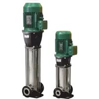
| Product type | Compact and automatic domestic wastewater lifting station |
| Supply voltage | 220-240 V ~ |
| Frequency | 50 Hz |
| Absorbed power (P1) | 490 W |
| Nominal current | 2.3 A |
| Cos φ | 0.95 |
| Protection rating | IP44 |
| Insulation class | F |
| Maximum manometric head | 8.0 m |
| Maximum flow rate | 6.9 m³/h |
| Maximum service pressure | 6 mWC |
| Maximum liquid temperature | 50 °C |
| Liquid pH | 4-10 |
| Sound level | < 70 dB(A) |
| Start level | 72 mm above bottom |
| Stop level | 52 mm above bottom |
| Approximate weight | 12 kg |
| Admissible water volume | 4, 6 or 9 litres |
Frequently Asked Questions - Genix 130 DAB
User questions about Genix 130 DAB
0 question about this device. Answer the ones you know or ask your own.
Ask a new question about this device
Download the instructions for your Pump in PDF format for free! Find your manual Genix 130 - DAB and take your electronic device back in hand. On this page are published all the documents necessary for the use of your device. Genix 130 by DAB.
USER MANUAL Genix 130 DAB
natural_image
Line drawing of a mechanical device with attached power outlet (no text or symbols)GENIX
natural_image
3D mechanical component diagram showing a cylindrical housing with mounting brackets and a circular base (no text or symbols)2

natural_image
Simple 3D illustration of a cylindrical object with three small protrusions on its length (no text or symbols)6. MANUTENZIONE
- Applications....10
- Pumped liquids....10
- Installation....10
- Electrical connection ....11
- Accessories....11
- Maintenance....11
6.1 Adjustment of run time....11
8.1 Storage....13
8.2 Transport 13
8.3 Weight 13
- Modifications and spare parts ....13
- Disposal 13
- Troubleshooting .... 14
ENGLISH
KEY
The following symbols have been used in the discussion:

SITUATION OF GENERAL DANGER.
Failure to respect the instructions that follow may cause harm to persons and property.
WARNINGS

Read this documentation carefully before installation. Installation and operation must comply with the local safety regulations in force in the country in which the product is installed.
Everything must be done in a workmanlike manner. Failure to respect the safety regulations not only causes risk to personal safety and damage to the equipment, but invalidates every right to assistance under guarantee.

Skilled personnel
It is advisable that installation be carried out by competent, skilled personnel in possession of the technical qualifications required by the specific legislation in force.
The term skilled personnel means persons whose training, experience and instruction, as well as their knowledge of the respective standards and requirements for accident prevention and working conditions, have been approved by the person in charge of plant safety, authorizing them to perform all the necessary activities, during which they are able to recognize and avoid all dangers. (Definition for technical personnel IEC 364)
The appliance may be used by children over 8 years old and by persons with reduced physical, sensory or mental capacities, or who lack experience or knowledge, on condition that they are under supervision or after they have received instructions concerning the safe use of the appliance and the understanding of the dangers involved. Children must not play with the appliance. Cleaning and maintenance intended to be carried out by the user must not be performed by children without supervision.

Safety
Use is allowed only if the electric system is in possession of safety precautions in accordance with the regulations in force in the country where the product is installed.(for Italy CEI 64/2)

The power supply cable must never be used to carry or shift the pump.

Never pull on the cable to detach the plug from the socket.
If the power cable is damaged, it must be replaced by the manufacturer or by their authorised technical assistance service, so as to avoid any risk.
Failure to observe the warnings may create situations of risk for persons or property and will void the product guarantee.
RESPONSIBILITY

The Manufacturer does not vouch for correct operation of the electropumps or answer for any damage that they may cause if they have been tampered with, modified and/or run outside the recommended work range or in contrast with other indications given in this manual.
The Manufacturer declines all responsibility for possible errors in this instructions manual, if due to misprints or errors in copying. The Manufacturer reserves the right to make any modifications to products that it may consider necessary or useful, without affecting their essential characteristics
GENERAL DESCRIPTION
The systems Genix are small, compact automatic lifting stations suitable for pumping domestic wastewater and sewage off places in private dwellings where wastewater cannot be led directly to the sewer by means of a natural downward slope.
The WCs and the other utilities connected to this system can be used
normally and require minimum maintenance.
The system will operate automatically as soon as the required level of water enters the tank.
1. APPLICATIONS
Genix systems are indicated exclusively for the processing of domestic waste water containing toilet paper and faecal matter.
Applications according to EN 12050-3.
WC with horizontal discharge according to standards EN33 or EN37
Installation with direct connection to toilet and in the same room as sanitary appliances.
A second toilet must be available above the backflow level.
The product must be fastened to the floor to prevent uplift and turning.
2. PUMPED LIQUIDS

The product is only suitable for pumping wastewater from a cabinet shower, bidet and/or washbasin as well as sewage from a toilet. Not for public and heavy commercial or industrial use, only limited number of users.
Any damage due to foreign bodies (wet wipes, food, cotton wool, tampons, sanitary pads, condoms, hair, cotton cloths, wood, metal or plastic objects) or due to pumping liquids such as solvents, strong chemical agents and oil will not be covered by the guarantee.
Ordinary liquids for cleaning of the appliances connected. pH value: 4-10.
Maximum using temperature 50°C

The product is designed for flush volumes of 4, 6 and 9 litres. A 4-litre flush is permissible only if the amount of solids in the pumped liquid is small.
3. INSTALLATION

The system must never be lifted by its power cable to carry it. The product must be accessible for maintenance and repair. The
product must be placed in a frost-free room to prevent the pumped liquid from freezing.

Make sure that all external pipework is adequately insulated. The discharge pipe must be made of rigid material, such as copper, or of rigid PVC with solvent-welded joints. To prevent the transmission of vibrations to buildings, make sure that the pipework is thoroughly fixed and that fittings cannot move and are not in contact with building parts.

Extension pipes between the toilet and the system must not be longer than 150 mm due to the increased risk of clogging.

Make sure to affix the "WaterMark" and "Prohibited Items" stickers in a clearly visible location of the device.

WaterMark
Certificate number: WM-022990 Technical specification: WMTS-106

Installation in accordance with Plumbing Code of Australia and AS/NZS3500.
4. ELECTRICAL CONNECTION

Make sure that the product is suitable for the supply voltage and frequency available at the installation site. The electrical connection must be carried out in accordance with local regulations.

The product must be earthed.

The installation must include an earth leakage circuit breaker for protection against earth fault currents. This ensures protection when using a Schuko plug or another plug with earth pin. The product must be connected to a mains switch with a minimum contact gap of 3 mm in all poles. In case of overtemperature, a thermal switch cuts out the motor and cuts it in automatically when it has
cooled sufficiently.
5. ACCESSORIES
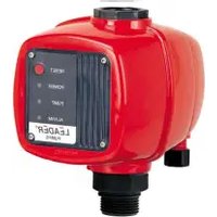
1- An alarm device for acoustic alarm in case of malfunction or high level in the tank is available as an accessory (noise level 75 dB(A)). Product number: 60166477.
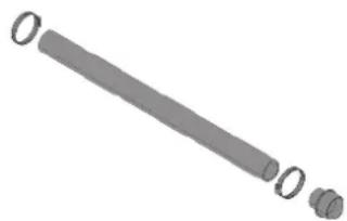
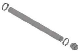
2- A kit containing: a hose (length 500mm) with adapter, available as an accessory. Product code 60168126
1

natural_image
3D mechanical component diagram showing a cylindrical housing with mounting brackets and a circular base (no text or symbols)2
natural_image
Simple 3D illustration of a cylindrical mechanical part with two small protrusions (no text or symbols)6. MAINTENANCE
The system does not require any particular maintenance, but we recommend checking the operation and couplings of the pipes at least once a year.
6.1 Adjustment of run time
The default setting ensures proper operation in most pipework. If the pipework is particularly long or short, it may be necessary to adjust the run time.
6.2 Service instructions
Thanks to the product design, service is easy in case of malfunction or blocked pump.
Digits in the following sections refer to the pictures in the appendix "Troubleshooting".

Before carrying out any service work, remove the fuse, pull out the plug, or switch off the power supply. Make sure that the power supply cannot be accidentally switched on. All rotating parts must have stopped moving. The product must only be serviced by trained service personnel.
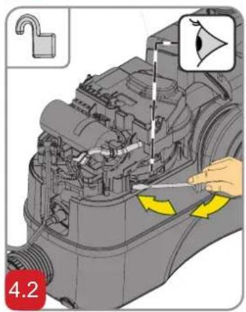
Impeller/grinder stuck
- Disconnect the power supply
- Remove the motor cover cap.
- Insert a screwdriver (min. 110 mm) through the plug hole and into the slot of the shaft end. Turn the shaft right and left to free the impeller/grinder from dirt.
Operation by means of a power drill
-
Disconnect the power supply
-
If the product cannot be operated by electrical power, the toilet and system can be emptied by means of a power drill.
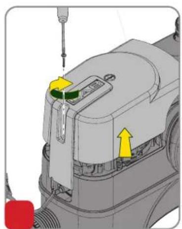
Pressure switch pipe clogged
- Disconnect the power supply
- Unscrew the screw of the motor cover and remove the cover
- If the water level is above the motor flange, empty the tank by means of the appropriate tap and the hose (supplied).
- Unscrew the screws of the board holder.
- Remove the pressure switch pipe.
- Clean the rubber hose and check the opening on the tank
Foreign body in tank
- Disconnect the power supply
- Unscrew the screw of the motor cover and remove the cover
- If the water level is above the motor flange, empty the tank by means of the appropriate tap and the hose (supplied).
- Unscrew the side screw of the motor ring
- Lift the motor flange to reduce the compression of the O-ring. Insert a screwdriver into the notch underneath the supply cable and press it down.
- Extract the complete motor unit by means of the handles (lift the unit
vertically before tilting it).
- Check and clean the tank and impeller/grinder.

Beware of the sharp edges on the grinder. Wear protective gloves.
Carbon filter
- Remove the filter cover
- Replace the filter
The carbon filter should be replaced once a year to ensure sufficient filter function.
Instead of using the activated carbon filter, the system can also vent through a vent pipe with diameter 20.
- TECHNICAL DATA
| Model Hz | Volt (V) P1 (W) | Amp (A) Cos φ | Hmax pump (m) | Flow max (m3/h) | ||
| Genix | 50 | 220-240 | 490 2.3 | 0.950.91 | 8.0 6.9 | |
| 60 115 | ||||||
| 60 127 | ||||||
| Genix Comfort | 50 | 220-240 | 490 2.3 | 0.950.91 | 8.0 6.9 | |
| 60 115 | ||||||
| 60 127 | ||||||
• Supply voltage: see electrical data plate
• Maximum operating pressure: 90 kPa / 0.9 bar / 13 psi
• Grade of motor protection: IP44
• Protection rating: F
- Noise level: <70dB(A) to 12050-3
- Delayed line fuses (version 220-240v): indicative values (Ampere)
• Duty: S3 -50% 1min. (30 sec on; 30 sec off). - Ambient temperature: da +5°C a +25°C
- Start and stop levels:
Start: 72 mm above bottom
Stop: 52 mm above bottom
The system pressure should not exceed 6 m head to guarantee a sufficient drain of the connected sanitary appliances (see rapid guide).
• Storage temperature: -10^ +40^
- Marking:


8. MANAGEMENT
8.1 Storage
All the pumps must be stored in a dry covered place, with possible constant air humidity, free from vibrations and dust.
They are supplied in their original pack in which they must remain until the time of installation.
8.2 Transport
Avoid subjecting the products to needless impacts and collisions.
8.3 Weight
The adhesive plate on the packaging indicates the total weight of the pump
9. MODIFICATIONS AND SPARE PARTS

Any modification made without prior authorisation relieves the manufacturer of all responsibility. All the spare parts used in repairs must be authentic and all accessories must be authorised by the manufacturer, in order to ensure maximum safety of the machines and of the systems in which they may be installed.

If the power supply cable of this appliance is damaged, the repair must be carried out by specialised personnel to prevent all risks.
10. 10. DISPOSAL DISPOSAL
This product or its parts must be disposed of in an environment-friendly manner and in compliance with the local regulations concerning the environment; use public or private local waste collection systems.
- TROUBLESHOOTING
| FAULTS | CHECKS(possible causes) | REMEDIES | |
| 1 | The motor does not start and does not produce noise when the starting level is reached in the tank. | A. Supply failure.B. Check the protection fuses. (if also the new fuse burns out, either the cable or the motor is faulty).C. Blocked impeller/grinder. (the thermal switch is off).D. Pressure switch pipe blocked. | A. Reestablish the power supply.B. Replace the fuse.Measure cable and motor. If cable or motor is defective, replace the defective parts.C. Free the impeller/grinder, and wait until the motor is cooled down and the thermal switch has reset.D. Remove the pressure switch pipe and clean the pipe. |
| 2 | Motor hums but does not operate. | A. Impeller/grinder stuck.B. Motor or capacitor defective.C. Control board defective. | A. Free the impeller/grinder and check that it can rotate freely.B. Replace the motor or capacitor.C. Replace the control board. |
| 3 | The motor works continuously or starts at regular intervals. | A. Water leaking from inlet into tank.B. Water leaking back into tank from discharge pipe.C. Pressure switch defective.D. Excess foam. | A. Check for leaking appliances.B. Check the non-return flap.C. Replace the pressure switch unit.D. Check the air vent/ Check that the basin is connected to the top connection / Provide an air vent (See Quick Guide). |
| 4 | Motor runs but does not evacuate water. | A. Pump or tank blocked.B. Air lock in pump or vent hole in pump housing blocked. | A. Remove blockage.B. Check operation of vent valve in the tank.Check that the carbon filter is not wet.C. Check that the vent hole in the pump housing is not blocked. |
| 5 | The service station drains slowly. | A. Discharge pipe is too long or has an excessive number of bends.B. The pump housing is leaky.C. Hydraulics or grinder blocked. | A. Increase discharge pipe size.Change pipework to reduce number of bends.Change bends to soft bends.B. Replace the pump housing (servicepart).C. Check and clean the hydraulics and grinder. |
| 6 | Rattling noise from the lifting station, but water is evacuated. | A. Foreign body hitting the impeller/grinder. | A. Remove the foreign body. |
| 7 | Odour from the tank. | A. Carbon filter contaminated. | A. Replace the carbon filter. |
TABLE DES MATIÈRES
Légende....15
Avertissements....15
ALLGEMEINE GEFAHRENSITUATION.
natural_image
3D mechanical component diagram showing a cylindrical housing with mounting holes and a circular base (no text or symbols)2

natural_image
Simple 3D illustration of a cylindrical mechanical part with three small circular ends (no text or symbols)6. WARTUNG
natural_image
3D mechanical component diagram showing a housing with mounting holes and a circular base (no text or symbols)
natural_image
Simple 3D illustration of a cylindrical object with two ends and one end, labeled '2' (no text or symbols on the object itself)6. ONDERHOUD
natural_image
3D technical illustration of a mechanical component with no visible text or symbols2
natural_image
Simple 3D illustration of a cylindrical object with three small protrusions, no text or symbols present6. MANTENIMIENTO
INNEHÅLLSFÖRTECKNING
natural_image
3D mechanical component diagram showing a cylindrical housing with mounting brackets and a circular base (no text or symbols)
natural_image
3D rendered mechanical part with two cylindrical ends and a long shaft, labeled '2' at bottom left (no text or symbols on the object itself)6. UNDERHÅLL
natural_image
3D mechanical component diagram with mounting base and cylindrical housing (no text or symbols)2

natural_image
Simple 3D illustration of a cylindrical rod with three small protrusions at one end (no text or symbols)6. BAKIM
natural_image
3D mechanical component diagram showing a cylindrical housing with mounting brackets and a circular base (no text or symbols)
natural_image
Simple 3D illustration of a cylindrical rod with three small protrusions (no text or symbols)1
natural_image
3D mechanical component diagram showing a cylindrical housing with mounting holes and a base plate (no text or symbols)
natural_image
Simple 3D illustration of a cylindrical object with three small protrusions, no text or symbols present.6. ÎNTRETINERE
natural_image
Isometric technical drawing of a mechanical assembly with mounting base and cylindrical component (no text or symbols)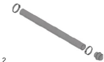
natural_image
3D rendered diagram of a cylindrical object with three small protrusions, labeled '2' at bottom left (no text or symbols on the object itself)6. MANUTENÇÃO
natural_image
3D mechanical component diagram showing a housing with mounting holes and a central circular housing (no text or symbols)2

natural_image
Simple 3D illustration of a cylindrical object with three small protrusions (no text or symbols)6. ΣΥΝΤΗΡΗΣΗ
natural_image
3D mechanical component diagram showing a cylindrical housing with mounting brackets and a circular base (no text or symbols)2
natural_image
Simple 3D illustration of a cylindrical object with two small protrusions, no text or symbols present6. ÚDRŽBA
natural_image
3D mechanical component diagram showing a housing with mounting holes and a cylindrical body (no text or symbols)2

natural_image
Simple 3D illustration of a cylindrical object with three small protrusions, no text or symbols presentFI SUOMI
6. KUNNOSSAPITO
natural_image
3D mechanical component diagram showing a housing with mounting holes and a cylindrical housing (no text or symbols)2

natural_image
Simple 3D illustration of a cylindrical object with three small protrusions (no text or symbols)6. KONSERWACJA
8.1 Opbevaring....97
8.2 Transport 97
8.3 Vægt....97
-
Ændringer og reservedele....97
-
Bortskaffelse....97
-
Fejlfinding....98
SIGNATURFORKLARING
natural_image
3D mechanical component diagram showing a cylindrical housing with mounting brackets and a circular base (no text or symbols)
natural_image
Simple 3D illustration of a rod with two small protrusions, no text or symbols present6. VEDLIGEHOLDELSE
natural_image
Isometric technical drawing of a mechanical component with mounting base and circular housing (no text or symbols)2

natural_image
Simple 3D illustration of a cylindrical mechanical part with three small circular ends (no text or symbols)6. ODRŽAVANJE
natural_image
3D technical illustration of a mechanical component with mounting base and housing (no text or symbols)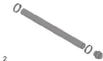
natural_image
3D rendered image of a cylindrical mechanical part with two small protrusions, labeled 'O' and marked with number '2' (no text or symbols on the object itself)natural_image
3D mechanical component diagram showing a housing with mounting holes and a circular base (no text or symbols)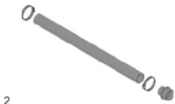
natural_image
Simple 3D illustration of a cylindrical object with two small protrusions, no text or symbols present6. ÚDRŽBA
natural_image
3D mechanical component diagram showing a housing with mounting holes and a cylindrical housing (no text or symbols)
natural_image
3D rendered mechanical part with cylindrical and stepped features (no text or symbols)6. VZDRŽEVANJE
natural_image
3D mechanical component diagram showing a cylindrical housing mounted on a base plate (no text or symbols)
natural_image
3D rendered mechanical part with three cylindrical features (no text or symbols)6. KARBANTARTÁS
natural_image
3D mechanical component diagram showing a housing with mounting holes and a cylindrical housing (no text or symbols)2

natural_image
Simple 3D illustration of a cylindrical object with three small protrusions (no text or symbols)6. ODRŽAVANJE
natural_image
3D mechanical component diagram showing a housing with mounting holes and a circular base (no text or symbols)2

natural_image
Simple 3D illustration of a cylindrical object with three small protrusions (no text or symbols)6. ПОДДРЪЖКА
natural_image
Simple 3D illustration of a cylindrical object with three small protrusions, no text or symbols present6. TECHNINÉ PRIEŽIŪRA
natural_image
3D technical illustration of a mechanical component with mounting base and cylindrical body (no text or symbols)2
natural_image
Pure diagram of a cylindrical mechanical part with three circular end caps (no text or symbols)
natural_image
Illustration of a person using a tool to adjust or install a luggage bag (no text or symbols visible)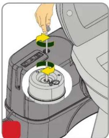
natural_image
Illustration of a hand using a tool to adjust or install a mechanical component, with no visible text or symbols.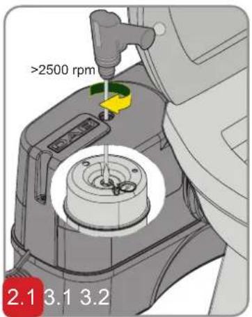
natural_image
Mechanical assembly diagram showing a component with yellow arrows indicating movement or force (no text or symbols present)
natural_image
Mechanical assembly diagram showing engine components and fluid flow (no text or symbols)
natural_image
3D mechanical assembly diagram showing internal components with yellow directional arrows indicating movement or force (no text or symbols)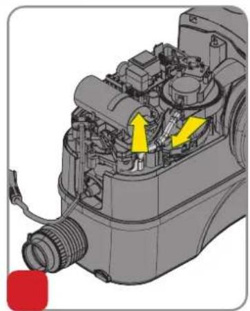
natural_image
Mechanical assembly diagram showing internal components with yellow arrows indicating flow or movement (no text or labels)

natural_image
Mechanical assembly diagram showing internal components and a magnified inset of a speaker (no text or labels)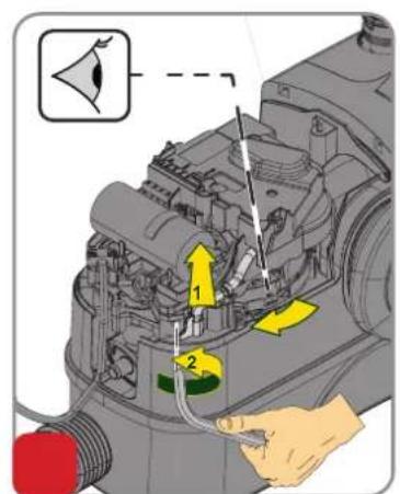

natural_image
Mechanical assembly diagram showing hands operating a component with yellow arrows indicating direction (no text or symbols)


natural_image
3D mechanical device with highlighted component and yellow arrow indicating direction (no text or symbols)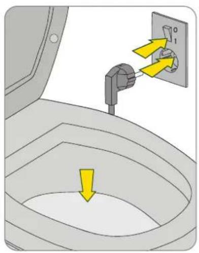
DAB PUMPS LTD.
6 Gilbert Court
Newcomen Way
Severalls Business Park
Colchester
Essex
C04 9WN - UK
salesuk@dwtgroup.com
Tel. +44 0333 777 5010
DAB PUMPS B.V.
office 308, 127247, Moscow - Russia
info.russia@dwtgroup.com
Tel. +7 495 122 0035
Fax +7 495 122 0036
DAB PUMPS HUNGARY KFT.
H-8800
Nagykanizsa, Buda Ernő u.5
Hungary
Tel. +36 93501700
DAB PUMPS OCEANIA PTY LTD
426 South Gippsland Hwy,
Dandenong South VIC 3175 – Australia
info.oceania@dwtgroup.com
Tel. +61 1300 373 677
DAB PUMPS IBERICA S.L.
Calle Verano 18-20-22
28850 - Torrejón de Ardoz - Madrid Spain
Info.spain@dwtgroup.com
Tel. +34 91 6569545
Fax: + 34 91 6569676
DAB PUMPS INC.
3226 Benchmark Drive
Ladson, SC 29456 - USA
info.usa@dwtgroup.com
Tel. 1-843-797-5002
Fax 1-843-797-3366
DAB PUMPS GmbH
Am Nordpark 3
41069 Mönchengladbach, Germany
info.germany@dwtgroup.com
Tel. +49 2161 47 388 0
Fax +49 2161 47 388 36
info.belgium@dwtgroup.com
Tel. +32 2 4668353
DAB PUMPS SOUTH AFRICA
Twenty One industrial Estate,
16 Purlin Street, Unit B, Warehouse 4
Olifantsfontein - 1666 - South Africa
info.sa@dwtgroup.com
Tel. +27 12 361 3997
DAB PUMPS POLAND SP. z.o.o.
No.40 Kaituo Road, Qingdao Economic &
Technological Development Zone
Qingdao City, Shandong Province - China
PC: 266500
sales.cn@dwtgroup.com
Tel. +86 400 186 8280
Fax +86 53286812210


- GENIX
- MANUTENZIONE
- KEY
- SITUATION OF GENERAL DANGER.
- WARNINGS
- RESPONSIBILITY
- GENERAL DESCRIPTION
- APPLICATIONS
- PUMPED LIQUIDS
- INSTALLATION
- ELECTRICAL CONNECTION
- ACCESSORIES
- MAINTENANCE
- Adjustment of run time
- Service instructions
- Impeller/grinder stuck
- Operation by means of a power drill
- Pressure switch pipe clogged
- Foreign body in tank
- Carbon filter
- MANAGEMENT
- Storage
- Transport
- Weight
- MODIFICATIONS AND SPARE PARTS
- 10. DISPOSAL DISPOSAL
- TABLE DES MATIÈRES
- ALLGEMEINE GEFAHRENSITUATION.
- WARTUNG
- ONDERHOUD
- MANTENIMIENTO
- INNEHÅLLSFÖRTECKNING
- UNDERHÅLL
- BAKIM
- ÎNTRETINERE
- MANUTENÇÃO
- ΣΥΝΤΗΡΗΣΗ
- ÚDRŽBA
- FI SUOMI
- KUNNOSSAPITO
- KONSERWACJA
- SIGNATURFORKLARING
- VEDLIGEHOLDELSE
- ODRŽAVANJE
- VZDRŽEVANJE
- KARBANTARTÁS
- ПОДДРЪЖКА
- TECHNINÉ PRIEŽIŪRA
- DAB PUMPS LTD.
- DAB PUMPS B.V.
- DAB PUMPS HUNGARY KFT.
- DAB PUMPS OCEANIA PTY LTD
- DAB PUMPS IBERICA S.L.
- DAB PUMPS INC.
- DAB PUMPS GmbH
- DAB PUMPS SOUTH AFRICA
- DAB PUMPS POLAND SP. z.o.o.
Brand : DAB
Model : Genix 130
Category : Pump