Sanicubic 1 WP - Pump Sanibroyeur - Free user manual and instructions
Find the device manual for free Sanicubic 1 WP Sanibroyeur in PDF.
User questions about Sanicubic 1 WP Sanibroyeur
0 question about this device. Answer the ones you know or ask your own.
Ask a new question about this device
Download the instructions for your Pump in PDF format for free! Find your manual Sanicubic 1 WP - Sanibroyeur and take your electronic device back in hand. On this page are published all the documents necessary for the use of your device. Sanicubic 1 WP by Sanibroyeur.
USER MANUAL Sanicubic 1 WP Sanibroyeur
natural_image
White plastic industrial component with a cylindrical inlet and flange, shown against a solid blue background (no text or symbols visible)SANICUBIC®1 WP
FR NOTICE D'INSTALLATION
UK INSTALLATION INSTRUCTIONS
DE INSTALLATIONSHINWEISE
IT STRUZIONI PER L'INSTALLAZIONE
ES MANUAL DE INSTALACIÓN
PT MANUAL DE INSTALAÇÃO
NL INSTALLATIE VOORSCHRIFTEN
SE INSTALLATIONSANVISNING
DK INSTALLATIONSVEJLEDNING
NO INSTALLASJONSANVISING
FI ASENNUSOHJEET
HU FELSZERELÉSI ÉS KEZELÉSI ÚTMUTATÓ
PL INSTRUKCJA INSTALACJI
RU ИНСТРУКЦИЯ ПО МОНТАЖУ И ЭКСПЛУАТАЦИИ
RO MANUAL DE INSTALARE
CZ NÁVOD K INSTALACI A POUŽÍVÁNÍ
TR KURULUM KILAVUZU
CN 用户应保留安装指南以备用
KR
flowchart
graph TD
    A["Water Inlet"] --> B["Toilet"]
    B --> C["Toilet"]
    C --> D["Washing Machine"]
    D --> E["Toilet"]
    E --> F["Toilet"]
    F --> G["Toilet"]
    G --> H["Toilet"]
    H --> I["Toilet"]
    I --> J["Toilet"]
    J --> K["Toilet"]
    K --> L["Toilet"]
    L --> M["Toilet"]
    M --> N["Toilet"]
    N --> O["Toilet"]
    O --> P["Toilet"]
    P --> Q["Toilet"]
    Q --> R["Toilet"]
    R --> S["Toilet"]
    S --> T["Toilet"]
    T --> U["Toilet"]
    U --> V["Toilet"]
    V --> W["Toilet"]
    W --> X["Toilet"]
    X --> Y["Toilet"]
    Y --> Z["Toilet"]
text_image
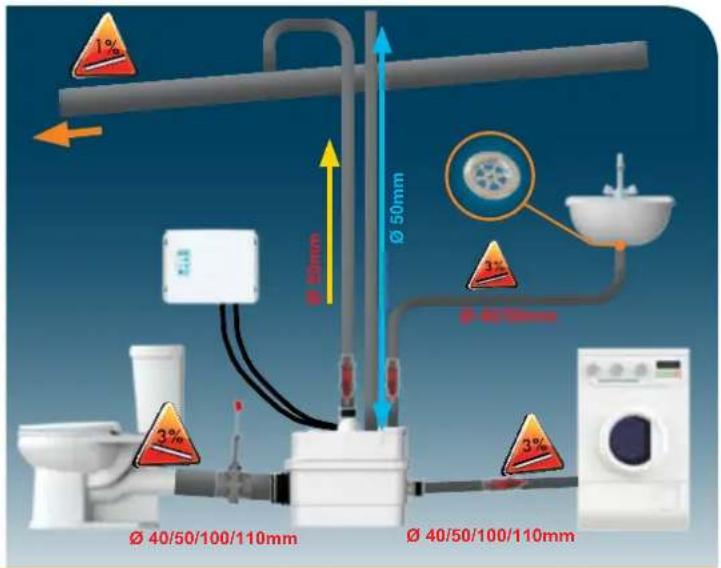
1% Ø 50mm Ø 40/50/100/110mm Ø 40/50/100/110mm 3% 3% Ø 50mm Ø 40/50mm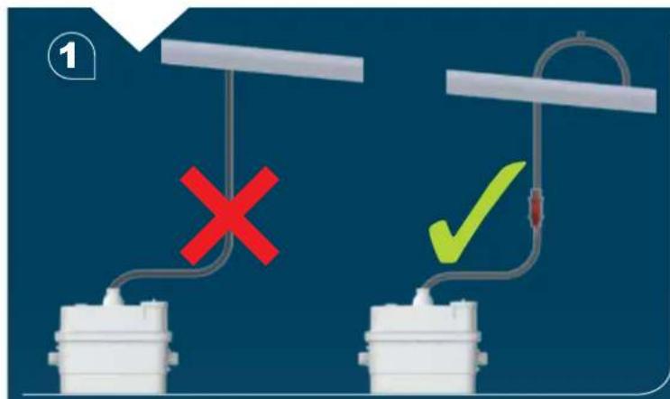
text_image
Diagram showing two mechanical setups with labeled symbols: red 'X' indicating failure and green checkmark indicating completion or finish.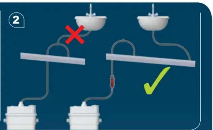
text_image
Diagram illustrating a medical procedure with labeled components and decision indicators
natural_image
3D rendering of a white toilet with a pipe and handle, no text or symbols visible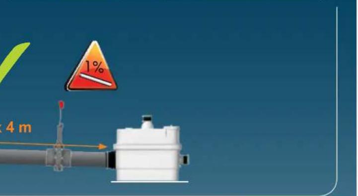
text_image
1% 4 m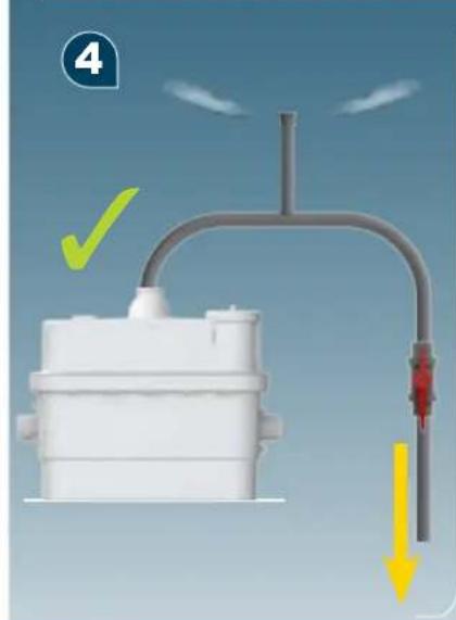
natural_image
Diagram of a mechanical or fluid system with a white tank, pipe, and directional arrows indicating flow or movement (no text or symbols)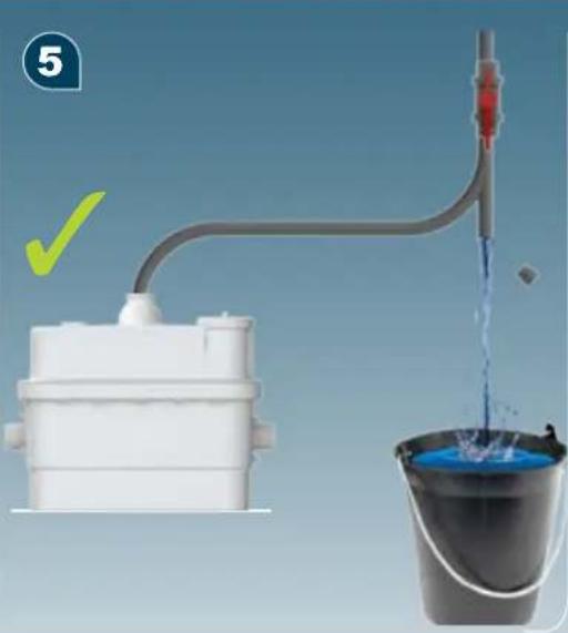
natural_image
Illustration of a water pump system with a bucket and tank, showing liquid flow and a checkmark (no text or symbols)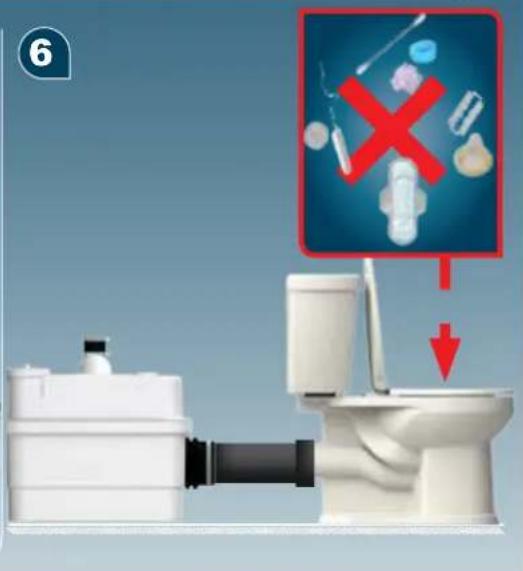
text_image
6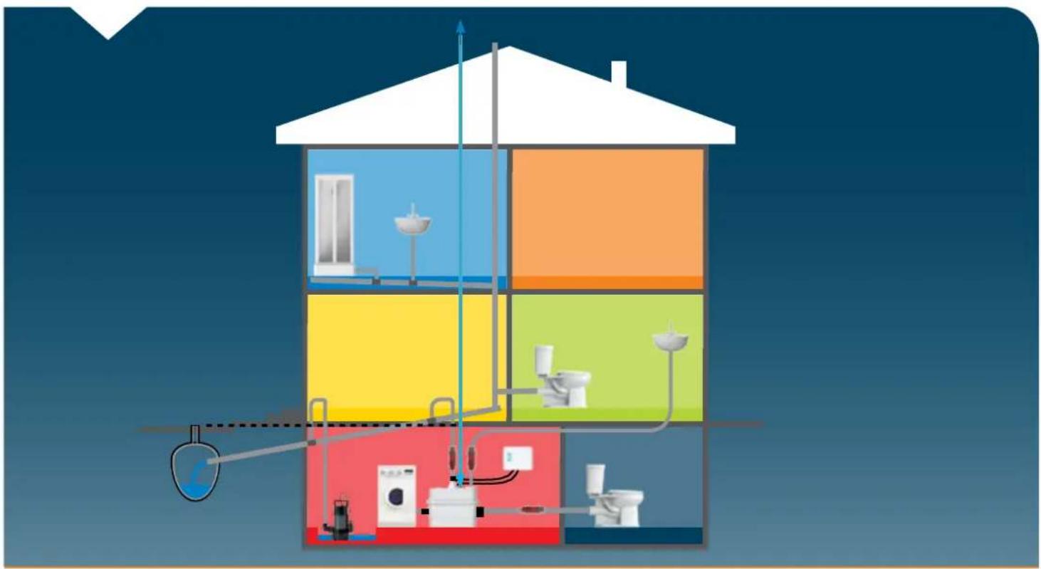
natural_image
Cross-sectional diagram of a multi-level bathroom with fixtures and water supply (no text or labels)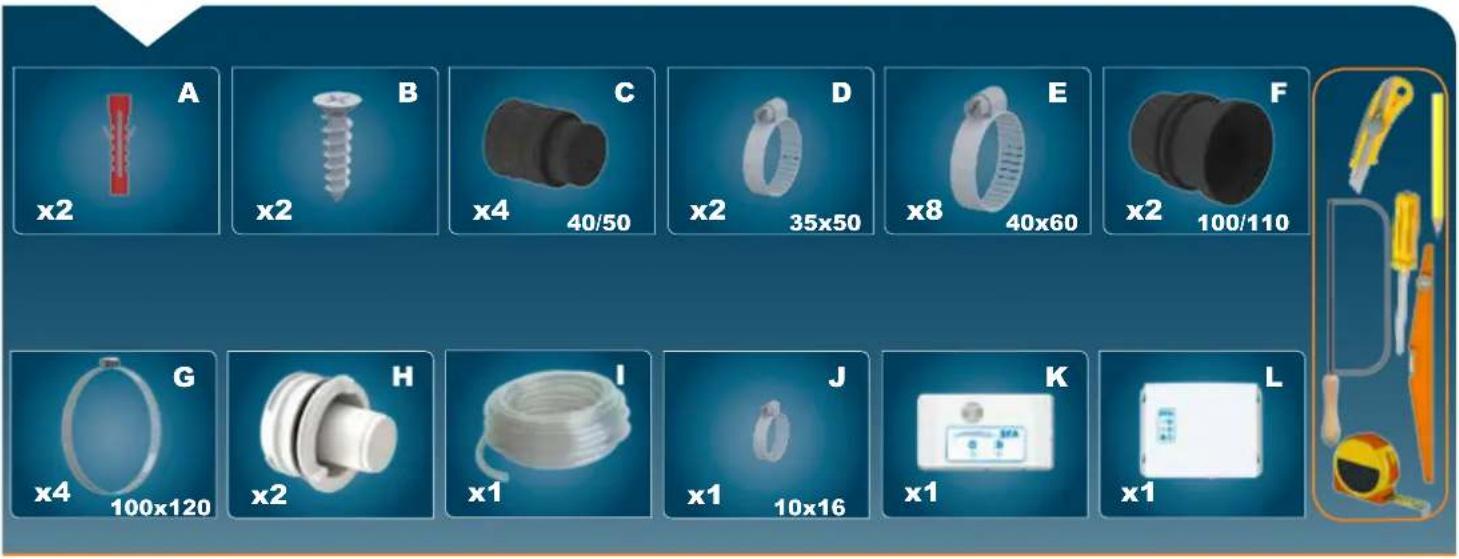
text_image
A x2 B x2 C x4 40/50 D x2 35x50 E x8 40x60 F x2 100/110 G x4 100x120 H x2 I x1 J x1 10x16 K x1 L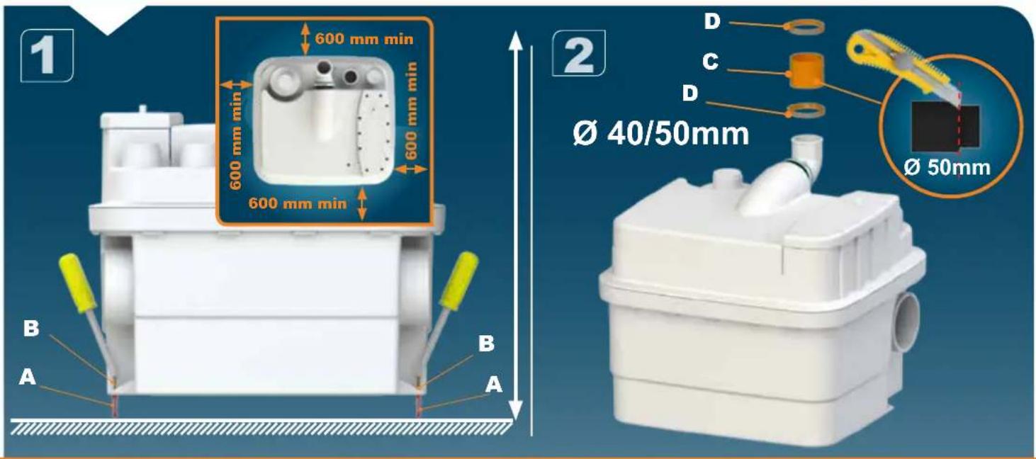
text_image
1 600 mm min 600 mm min 600 mm min 600 mm min 2 Ø 40/50mm D C D Ø 50mm B A B A
natural_image
White plastic industrial container with pipes and a yellow-green outline, no visible text or symbols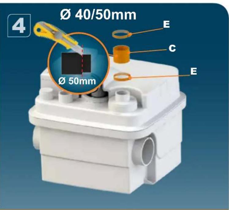
text_image
Ø 40/50mm Ø 50mm E C E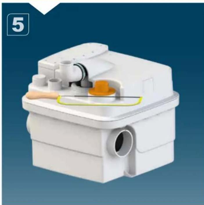
natural_image
3D rendering of a white plastic mechanical device with internal components and a yellow highlight (no text or symbols visible)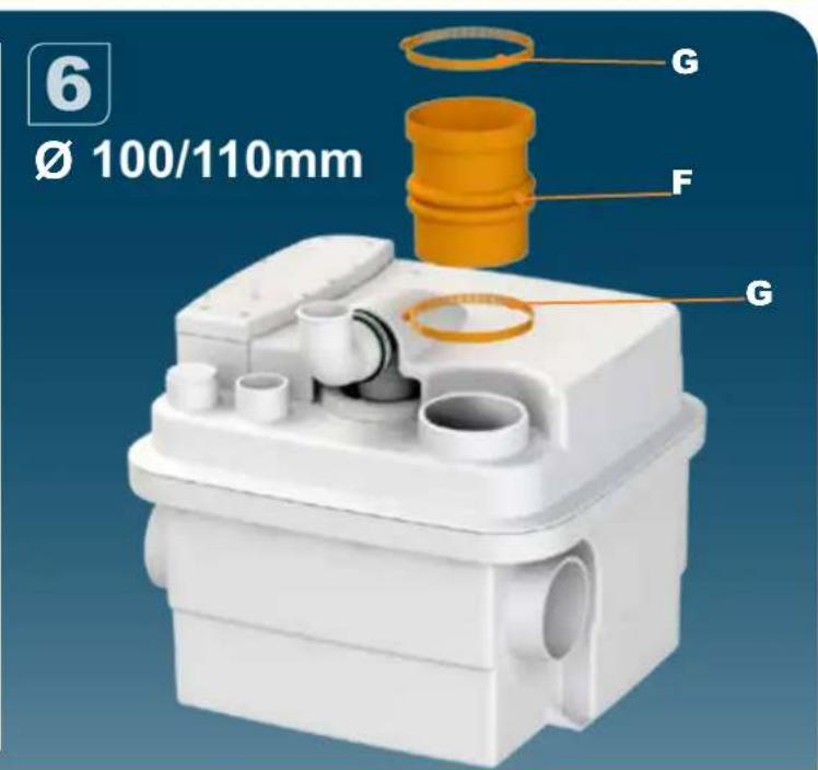
text_image
6 Ø 100/110mm G F G
natural_image
3D rendered white plastic mechanical component with internal pipes and a yellow wire, no visible text or symbols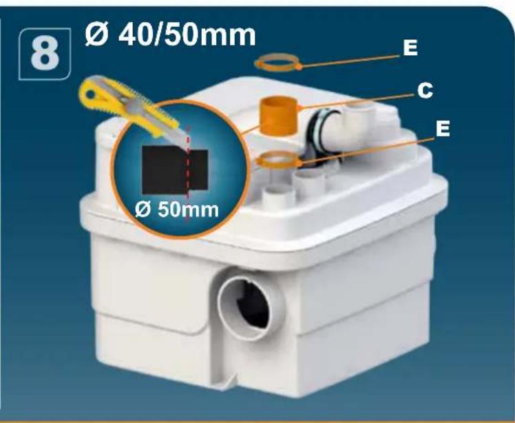
text_image
Ø 40/50mm Ø 50mm E C E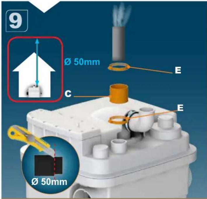
text_image
9 Ø 50mm E C E Ø 50mm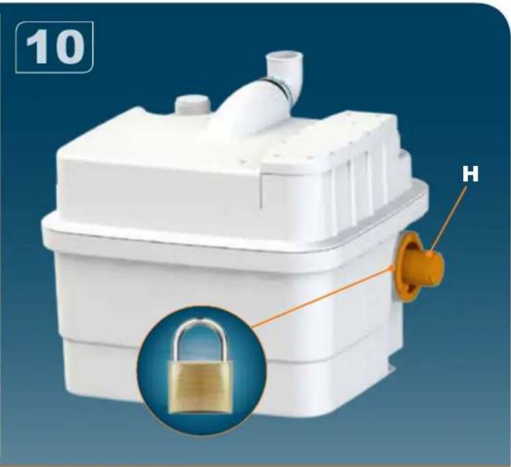
natural_image
White plastic industrial component with a lock and labeled part 'H', shown with an inset close-up of the lock (no text or symbols on the device itself)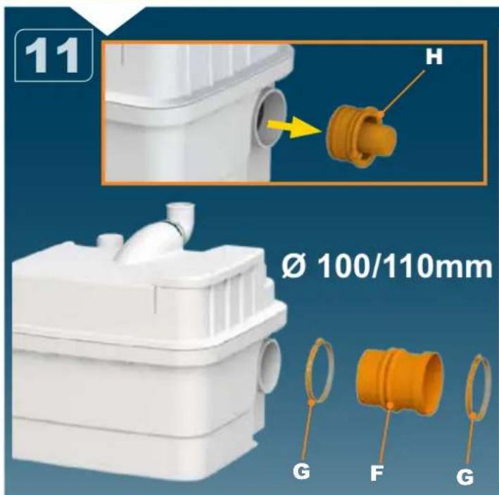
text_image
11 H Ø 100/110mm G F G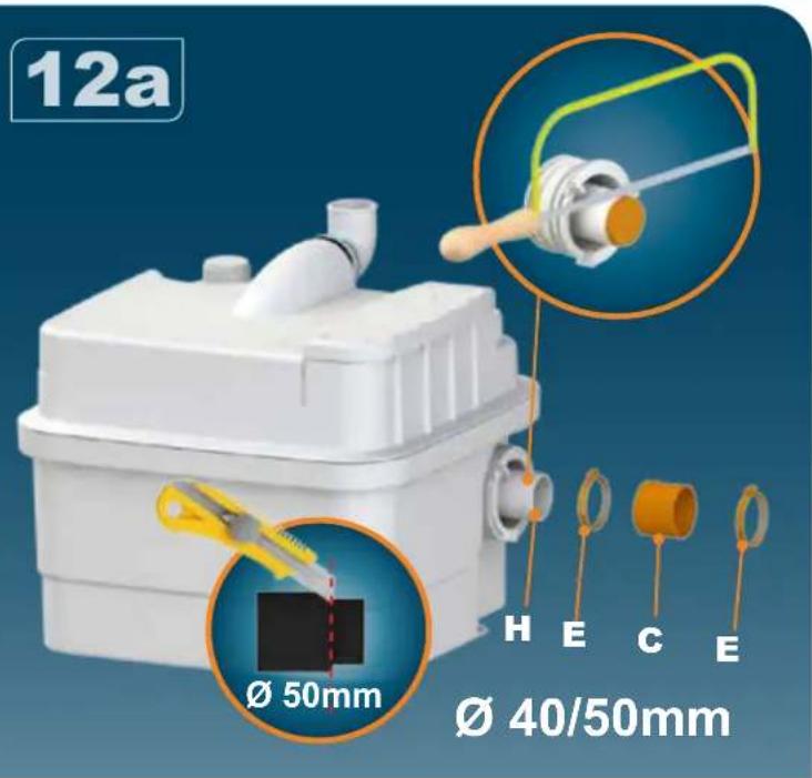
text_image
12a Ø 50mm H E C E Ø 40/50mm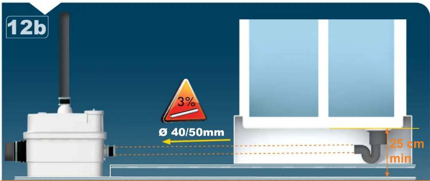
text_image
12b Ø 40/50mm 3% 25 cm min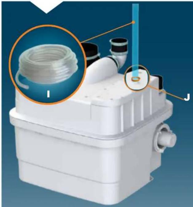
natural_image
3D rendering of a white plastic industrial device with a coiled hose and labeled components (I and J), no readable text or symbols beyond labels.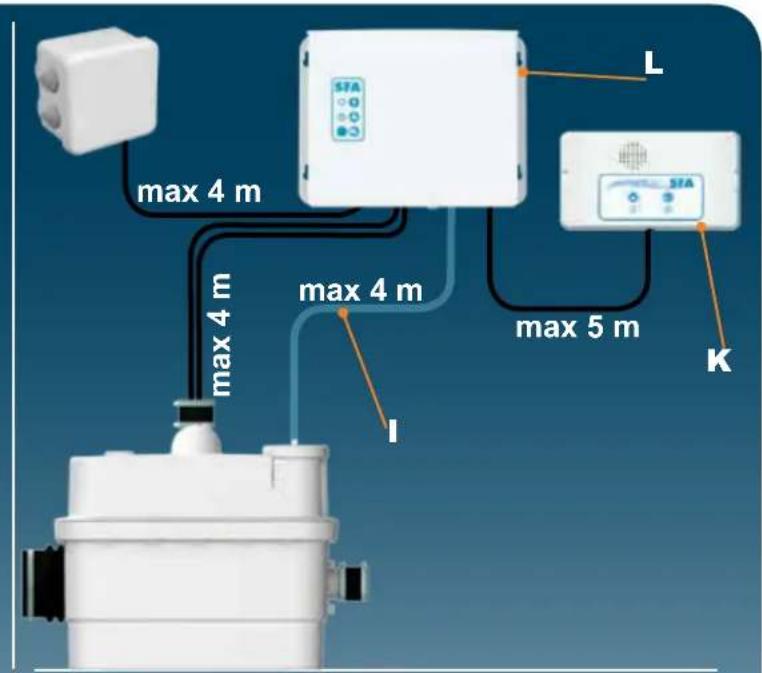
text_image
max 4 m max 4 m max 4 m max 5 m L STA STA K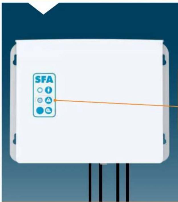
text_image
SFA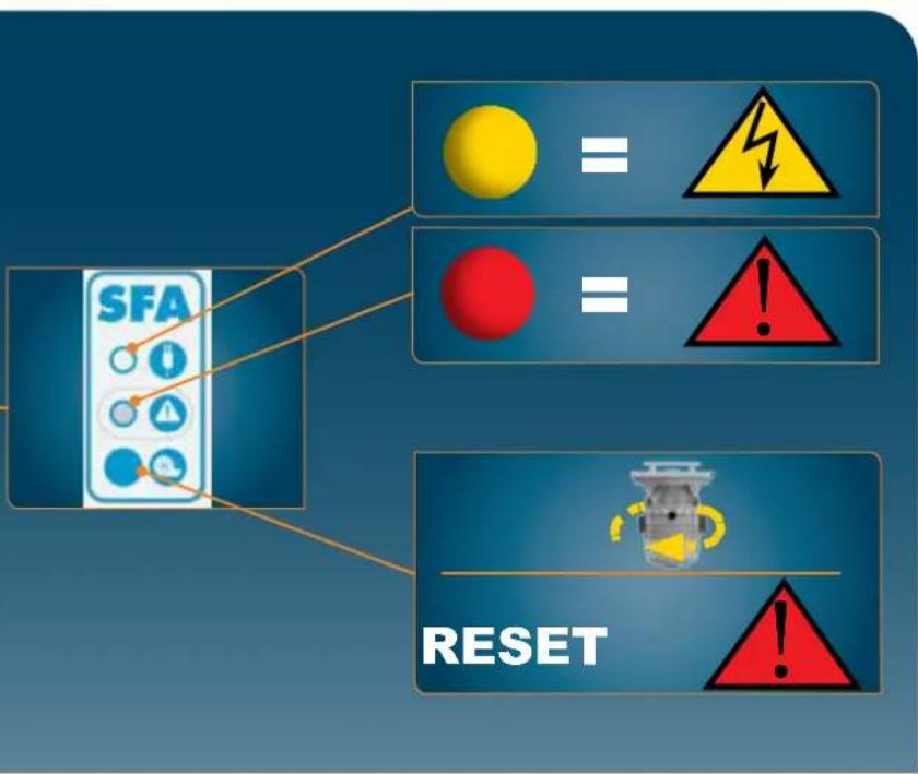
flowchart
graph TD
    A["SFA"] --> B["="]
    A --> C["="]
    A --> D["="]
    A --> E["="]
    F["RESET"] --> G["="]
    F --> H["="]
    F --> I["="]
text_image
Warning sign with red circle, equals sign, and exclamation mark on blue background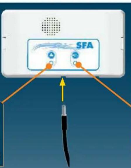
text_image
SFA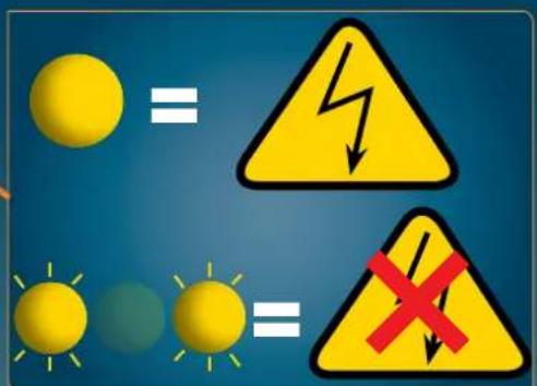
text_image
Safety warning symbols showing sun and lightning bolt versus warning triangle with red X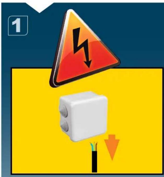
text_image
1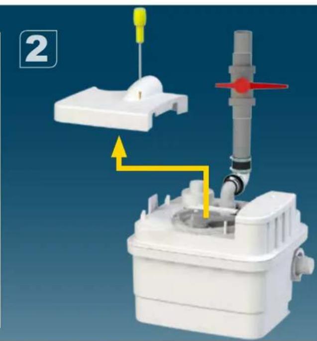
natural_image
3D diagram of a medical or industrial device with yellow and red directional arrows indicating flow or movement (no text or symbols)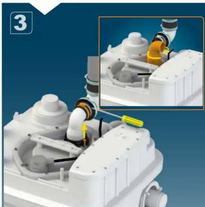
natural_image
Close-up of a white industrial robotic device with pipes and a yellow tool inserted, showing internal components and a close-up inset (no text or symbols visible)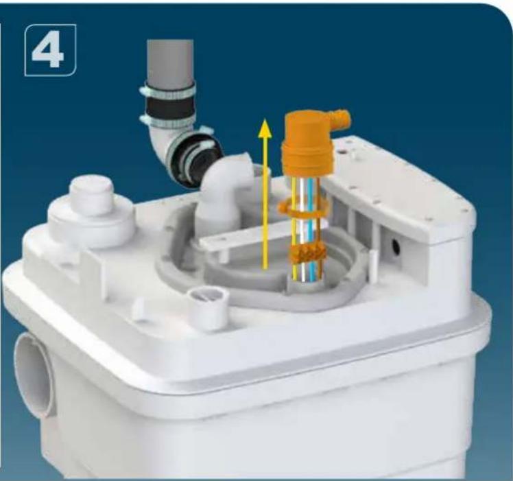
natural_image
3D rendering of a white industrial device with internal components and piping (no visible text or symbols)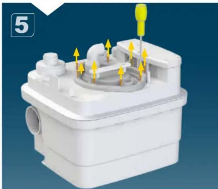
natural_image
3D rendering of a white plastic mechanical housing with yellow directional arrows indicating internal components (no text or symbols)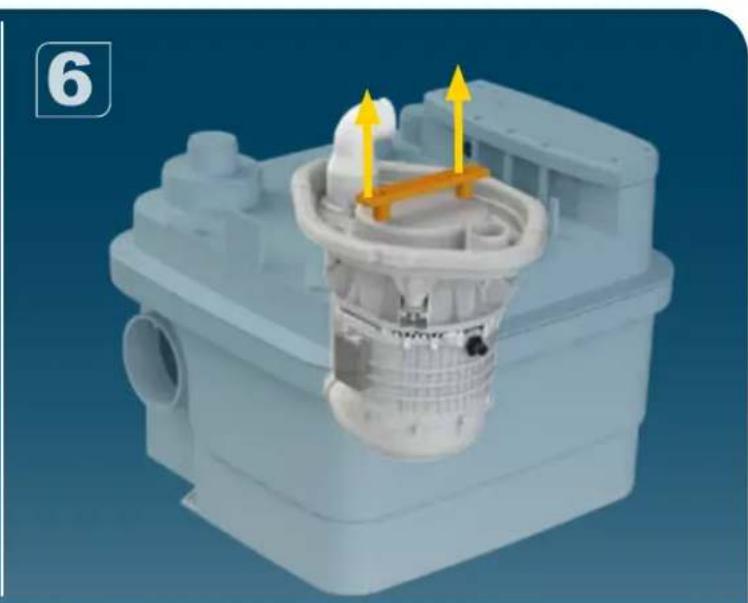
natural_image
3D rendered mechanical component with yellow arrows indicating flow or movement, no visible text or symbols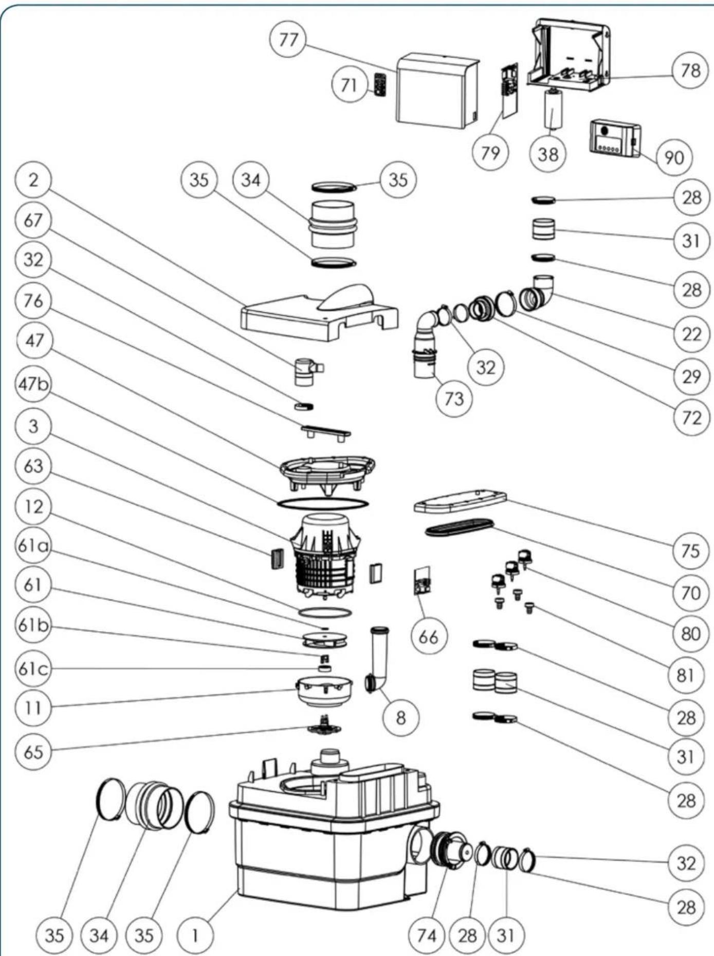
text_image
Exploded view diagram of a mechanical device with numbered parts for identification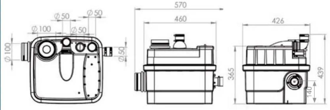
text_image
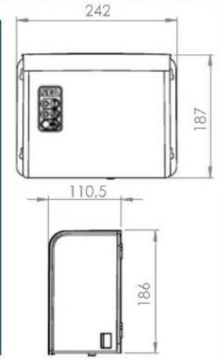
242 187 110.5 186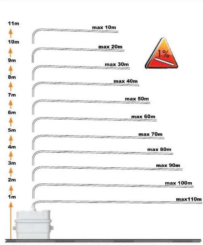
bar
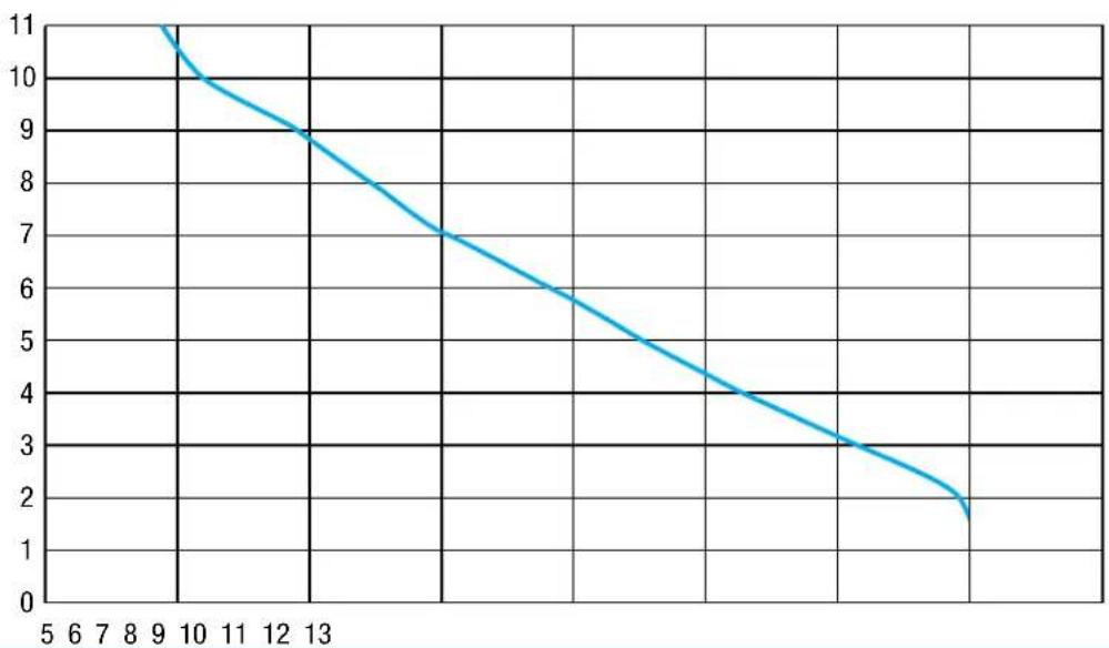
| Distance (m) | Maximum Distance (m) | |---|---| | 11 | max 10 | | 10 | max 20 | | 9 | max 30 | | 8 | max 40 | | 7 | max 50 | | 6 | max 60 | | 5 | max 70 | | 4 | max 80 | | 3 | max 90 | | 2 | max 100 | | 1 | max110 | The chart displays a descending trend in maximum distance as distance increases from 1m to 11m.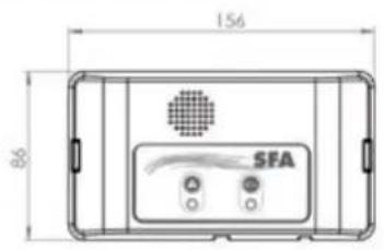
text_image
156 86 SFA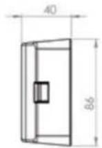
SANICUBIC 1WP
EN 12050-1
R 350
220-240 V - 50 Hz
1500 W - 6A - ⏚ CLASS 1
IP68 - 16 Kg
Max temperature 70°C (max 5 min)
Tank volume : 32 L
H (m)
line
| x | y | |----|----| | 9 | 11 | | 13 | 9 | | 14 | 7 | | 15 | 6 | | 16 | 5 | | 17 | 4 | | 18 | 3 | | 19 | 2 | | 20 | 1.5|Q (^3 /)
FRANCE
SOCIÉTÉ FRANÇAISE
D'ASSAINISSEMENT
Howard House, The Runway
South Ruislip Middx..
HA4 6 SE
Tel. +44 208 842 0033
Fax +44 208 842 1671
IRELAND
SANIRISH Ltd
IDA Industrial Estate
Edenderry - County Offaly
Tel. + 353 46 9733 102
Fax + 353 46 97 33 093
AUSTRALIA
SANIFLO (Australasia) Pty Ltd
Unit 9/10, 25 Gibbs Street
Chatswood NSW 2067
Tel. +61 298 826 200
Fax +61 298 826 950
DEUTSCHLAND
SFA SANIBROY GmbH
Waldstr. 23 Geb. B5 - 63128
Dietzenbach
Tel. (060 74) 30928-0
Fax (060 74) 30928-90
ITALIA
SFA ITALIA spa
Via del Benessere, 9
27010 Siziano (PV)
Tel. 03 82 61 81
Fax 03 82 61 8200
ESPAÑA
SFA S.L.
C/ Vinyalets,1 - P.I. Can Vinyalets
08130 Sta. - Perpètua de Mogoda -
Barcelona
Tel. +34 93 544 60 76
Fax +34 93 462 18 96
PORTUGAL
SFA, Lda.
Sintra Business Park, ed.01-
1°P2710-089 SINTRA
Tel. +35 21 911 27 85
Fax +35 21 957 70 00
РОССИЯ
SFA РОССИЯ
Service information: www.sfa.biz
| 100.0 | |
| 100.0 | 100.0 |
| 100.0 | 100.0 |
| 100.0 | 100.0 |
| 100.0 | 100.0 |
| 100.0 | 100.0 |
| 100.0 | 100.0 |
| 100.0 | 100.0 |
| 100.0 | 100.0 |
| 100 25 | 100 25 |
| 100 35 | 100 35 |
| 100 45 | 100 45 |
| 100 55 | 100 55 |
| 100 65 | 100 65 |
| 100 75 | 100 75 |
| 100 85 | 100 85 |
| 100 95 | 100 95 |
| 100 105 | 100 105 |
| 100 115 | 100 115 |
| 100 125 | 100 125 |
| 100 135 | 100 135 |
| 100 145 | 100 145 |
| 100 155 | 100 155 |
| 100 165 | 100 165 |
| 100 175 | 100 175 |
| 100 185 | 100 185 |
| 100 295 | 100 295 |
| 100 395 | 100 395 |
| 100 495 | 100 495 |
| 100 695 | 100 695 |
| 100 795 | 100 795 |
| 100 895 | 100 895 |
| 100 995 | 100 995 |
| 100 1295 | 1295 |
| \( {1295}\;{2495}\;{3695}\;{4895}\;{6295}\;{7295}\;{8495}\;{9695}\;{12295}\;{24295}\;{36295}\;{48295}\;{62295}\;{72295}\;{84295}\;{96295}\;{12229}\;{24229}\;{36229}\;{48229}\;{62229}\;{72229}\;{84229}\;{96229}\;{12229}\;{24229}\;{36229}\;{48229}\;{62229}\;{72229}\;{84229}\;{96229}\;{12229}\;{24229}\;{36229}\;{48229}\;{72229}\;{84229}\;{96229}\;{12229}\;{24229}\;{36229}\;{48229}\;{62229}\;{72229}\;{84229}\;{96229}\;{12229} |
FR INFORMATIONS COMPLÉMENTAIRES IMPORTANTES
UK IMPORTANT ADDITIONAL INFORMATION
DE WICHTIGE ZUSÄTZLICHE INFORMATIONEN
IT INFORMAZIONI AGGIUNTIVE IMPORTANTI
ES INFORMACIÓN COMPLEMENTARIA IMPORTANTE
PT BR INFORMAÇÕES COMPLEMENTARES IMPORTANTES
NL BELANGRIJKE EXTRA INFORMATIE
SE ANNAN VIKTIG INFORMATION
DK VIGTIGE SUPPLERENDE OPLYSNINGER
NO VIKTIG TILLEGGSINFORMASJON
FI TÄRKEITÄ LISÄTIETOJA
PL WAŻNE INFORMACJE DODATKOWE
RU UA ВАЖНАЯ ДОПОЛНИТЕЛЬНАЯ ИНФОРМАЦИЯ
RO INFORMATII SUPLEMENTARE IMPORTANTE
CZ DŮLEŽITÉ DOPLŇUJÍCÍ INFORMACE
TR ÖNEMLİ EK BİLGİLER
JP 重要な説明事項
CN 重要补充信息
KR 중요한 추가 정보
TW 重要補充信息
HR VAŽNE DODATNE INFORMACIJE
AR معلومات إضافية هامة
1 AVERTISSEMENT
natural_image
Close-up of electronic components including capacitors, resistors, and a switch (no readable text or symbols)text_image
ON 1 2 SW1This pumping station is (manufactured in a factory which is quality) certified to ISO 9001. Installed and used correctly, the unit will give consistent and reliable service.

This device is not designed for persons (including children) with limited physical, sensory or mental abilities, or those with minimal experience and knowledge, unless they are monitored and are given the necessary instructions for using the device, with the help of a person responsible for their safety. Monitor children and make sure they do not play with the device.
2 APPLICATIONS
SANICUBIC® 1 and SANICUBIC® 1 WP are pumping stations specially developed for individual use (detached house or small commercial premises).
SANICUBIC® 2 Classic and SANICUBIC® 2 Pro are pumping stations specially developed for individual, commercial and small community use (small buildings, shops, public places).
SANICUBIC® 2 XL is a pumping station specially designed for community use (professional buildings, restaurants, industries, schools, hotels or shopping centres).
These devices comply with the EN 12050-1 standard (pumping station for waste water containing faeces) as well as the European directives on construction products, electrical safety and electromagnetic compatibility.
3 INSTALLATION
The SANICUBIC ^® must be installed in compliance with standard EN12056-4. The equipment must be commissioned and maintained by a qualified professional specialist.
1- Attention: the space in which the SANICUBIC ^® is to be installed must be large enough to leave at least 600 mm of working room around and above the unit to facilitate such maintenance work as may be required.
There must be sufficient lighting, and it must be sufficiently well ventilated and protected from freezing.
2-Isolating valves (not supplied) must be fitted on waste inlets (especially the 110mm inlets) and on the discharge to ensure that any service/maintenance may be carried out safely).
3- The discharge pipe must be fitted so as to avoid all back flow from the drainage system (see the examples in drawing). Back flow can be avoided by installing an anti-back flow riser reaching a high point above the maximum back flow level.
Comment: In the absence of local information to the contrary, the maximum back flow level corresponds to street level (roadway, pavements, etc.). Continue the discharge pipework after the anti-backflow riser, using a larger diameter pipe.
4- If the SANICUBIC ^® is installed in a space such as a pit for example, we would recommend the fitting of a bilge pump in case of flooding.
5- The lifting station must be vented with an open vent outlet at roof level. Do not fit an air admittance vale as the pump will not function correctly.
ELECTRICAL CONNECTIONS
1- The electrical installation work must be carried out by a qualified electrician.
The electrical installation must comply with the standards in force in the country concerned
2- The power supply must be of the class 1 type. The unit must be connected via an earthed connection box. The electric power circuit must be protected by a high-sensitivity 30mA differential circuit breaker set at 20A . The connection must be used solely to power the SANICUBIC. If the power lead on the unit is damaged, it must be replaced by the manufacturer or its after-sales service to avoid all danger.
4 COMMISSIONING
1- Once the plumbing and electrical connections have been made, check that the connections are watertight by letting water flow successively through each inlet used. Make sure that the unit is operating correctly by carrying out at least two start cycles with water to test the system.
2 - WARNING! Do not operate the motors manually (using the key pad) where no water has entered the SANICUBIC ^® . Operation without water damages the maceration system.
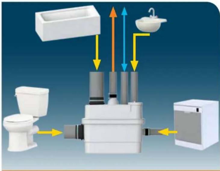
OPERATING PRINCIPLE
- SANICUBIC® 1/SANICUBIC® 1® WP contains 1 pump equipped with a high performance shredding system.
- SANICUBIC® 2 Classic/SANICUBIC® 2 Pro contains two independent pumps. Each of these pumps is equipped with a high performance shredding system.
Both pumps operate alternately to ensure even ware. In case of surcharge operation, both motors run simultaneously (or if one pump fails, the other takes over).
- SANICUBIC® 2 XL contains two independent pumps, each with a clearance of 55 mm.
The tank is equipped with three dip tubes, two of which control motor activation for double security, and the third controls the alarm system.
- 2 Long dip tubes
During normal operation, as soon as the effluents reach the long tube's activation level in the tank, the pumping system switches on.
- Short dip tube
During surcharge operation, if the effluents reach the highest level in the tank (short tube), an audible and visual alarm system is activated and the pumping system switches on (if it is not faulty).
If the water level inside the device is abnormally high, the high level diptube microswitch will activate the motor and the alarm LED lights up red. If this LED flashes red, it indicates a detection problem for the normal water level (Long dip tube).
Time alarm:
If the motor runs continuously for more than 1 minute, the red LED alarm lights up.
2/ Reset alarm:
The button on the keypad will only allow you to turn off the red LED (it will turn green) if the problem that triggered the alarm has been resolved. It also allows you to stop the buzzing from the remote alarm control.
Mains alarm:
- If the LED is off, there is no power supply.
- When the device is powered on again, and the LED flashes green, this indicates that the mains voltage has temporarily disappeared.
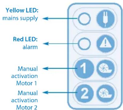
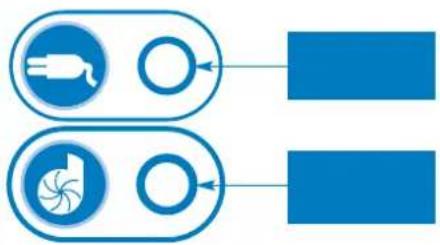
LED
GREEN: Power on
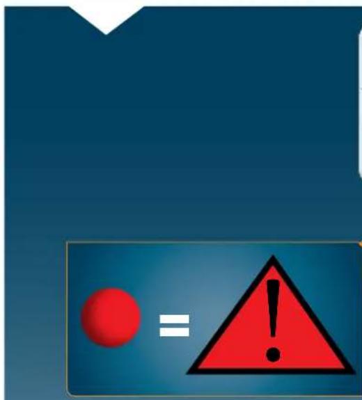
RED: Alarm

BUTTON
Manual motor
activation
Alarm reset
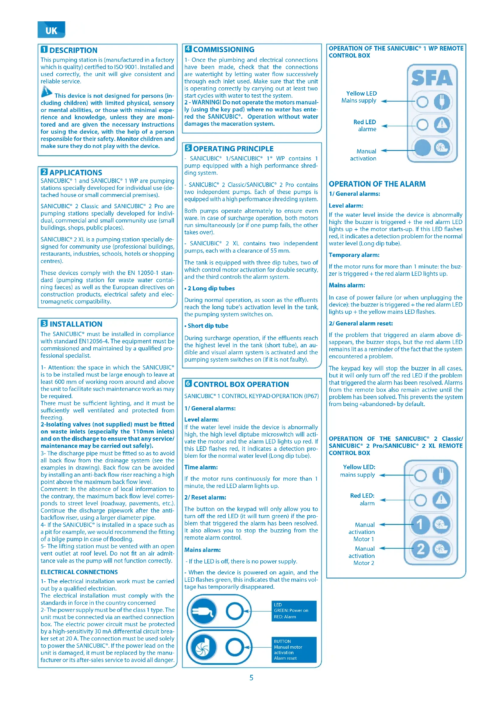
text_image
SFA Yellow LED Mains supply Red LED alarme Manual activationOPERATION OF THE ALARM
1/ General alarms:
Level alarm:
If the water level inside the device is abnormally high: the buzzer is triggered + the red alarm LED lights up + the motor starts-up. If this LED flashes red, it indicates a detection problem for the normal water level (Long dip tube).
Temporary alarm:
If the motor runs for more than 1 minute: the buzzer is triggered + the red alarm LED lights up.
Mains alarm:
In case of power failure (or when unplugging the device): the buzzer is triggered + the red alarm LED lights up + the yellow mains LED flashes.
2/ General alarm reset:
If the problem that triggered an alarm above disappears, the buzzer stops, but the red alarm LED remains lit as a reminder of the fact that the system encountered a problem.
The keypad key will stop the buzzer in all cases, but it will only turn off the red LED if the problem that triggered the alarm has been resolved. Alarms from the remote box also remain active until the problem has been solved. This prevents the system from being «abandoned» by default.
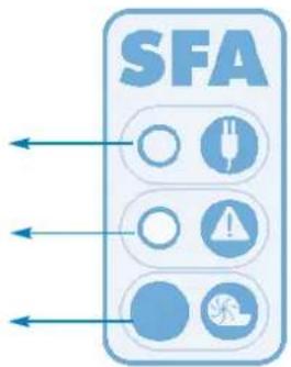
OPERATION OF THE SANICUBIC® 2 Classic/SANICUBIC® 2 Pro/SANICUBIC® 2 XL REMOTE CONTROL BOX
text_image
Yellow LED: mains supply Red LED: alarm Manual activation Motor 1 Manual activation Motor 2OPERATION OF THE ALARM
1/ General alarms:
Level alarm:
If the water level inside the device is abnormally high: the buzzer is triggered + the red alarm LED lights up + both motors start-up. If this LED flashes red, it indicates a detection problem for the normal water level (Long dip tube).
Temporary alarm:
If one of the two motors runs for more than 1 minute: the buzzer is triggered + the red alarm LED lights up + the other motor starts-up.
Mains alarm:
In case of power failure (or when unplugging the device): the buzzer is triggered + the red alarm LED lights up + the yellow mains LED flashes.
2/ General alarm reset:
If the problem that triggered an alarm above disappears, the buzzer stops, but the red alarm LED remains lit as a reminder of the fact that the system encountered a problem.
One of the two keypad keys will stop the buzzer in all cases, but it will only turn off the red LED if the problem that triggered the alarm has been resolved. Alarms from the remote box also remain active until the problem has been solved. This prevents the system from being left unknowingly in a faulty state
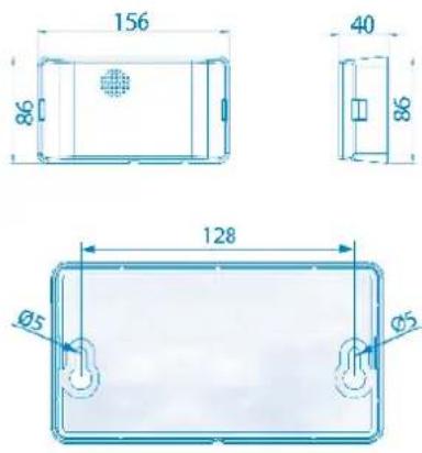
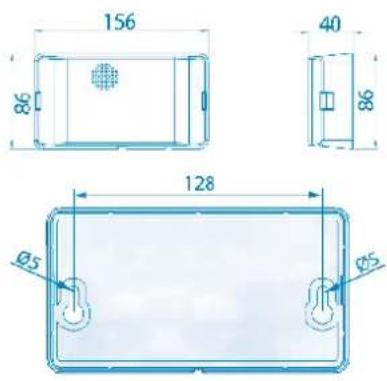
7 OPERATION OF THE ALARM UNIT
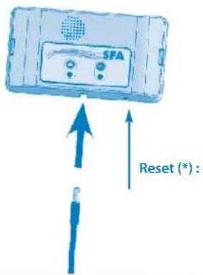
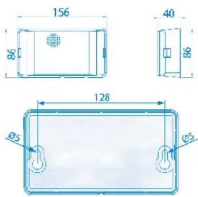
For wall mounting of the unit, use the following image as a guide:
OPERATION OF THE SANICUBIC® 1/SANICUBIC® 1 WP/SANICUBIC® 2 Classic/SANICUBIC® 2 XL WIRED ALARM UNIT
The SANICUBIC ^® alarm unit does not require a separate power supply. The power is supplied through the SANICUBIC ^® . In case of power failure, the alarm unit's battery takes over.
text_image
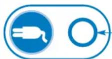
SFA Reset (*):Connection of the alarm unit to the device:
Connect the alarm cable directly to the unit.
1/ The red general alarm LED reproduces the operation of the corresponding LED on the SANICUBIC® control panel. The alarm unit sounds as long as the fault is present. To stop the alarm, press the reset (*) button on the device's keypad or the button under the alarm unit.
2/ The yellow «mains» LED indicates the power supply status of the alarm unit
-steadily glowing light = live SANICUBIC ^® connected to the mains supply
-flashing = power failure on the SANICUBIC ^® .
OPERATION OF THE SANICUBIC® 2 PRO H/F ALARM UNIT
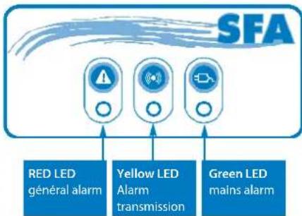
flowchart
graph TD
    A["Red LED général alarm"] --> B["Yellow LED Alarm transmission"]
    C["Green LED mains alarm"] --> B
    B --> D["SFA"]
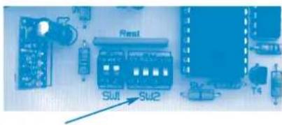
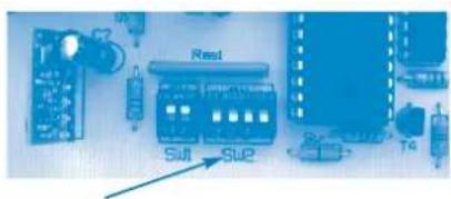
The alarm unit is in HF connection -868 Mhz HF with the SANICUBIC® 2 Pro. It receives various alarm information from it. If other devices operating in HF are disrupted by the system
(or vice versa), a commutation of the HF -868 Mhz coding has been anticipated, which connects the base card and the remote alarm unit.
In the event of interference with other HF devices or other SANICUBIC® 2 Pro devices nearby, unplug the unit and the remote module, switch one or more of the 4 switches of the device's card (SW2).
natural_image
Close-up of an electronic circuit board with labeled components (no readable text or symbols)and do the same on the remote unit's card.
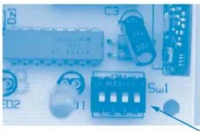
natural_image
Close-up of electronic components including an integrated circuit, capacitors, and a switch (no readable text or symbols)Warning: the code must be the same for the 2 cards.
The alarm unit has 3 LEDs and 1 buzzer.
1/ The red «general alarm» LED reproduces the operation of the corresponding LED on the SANICUBIC® control panel.
2/ The yellow «HF reception» LED reproduces the operation of the SANICUBIC® control panel's yellow mains LED:
- steady light = transmission OK, the SANICUBIC® control panel connected to the mains supply
- blinking = transmission OK, but power failure on the SANICUBIC® control panel (which then runs on battery)
- off = no HF reception (check that the code is the same as the SANICUBIC® control panel or loss of HF signal (too far away) discharged or failure of the SANICUBIC® control panel.
3/ Green «mains» LED indicates the power status of the alarm remote unit:
- steady light = live unit connected to the mains supply
- flashing = mains failure on the unit (which is therefore operating on battery)
-off = failure of the unit or discharged battery
4/ The buzzer sounds continuously during an alarm. It stops buzzing if the cause of the alarms disappear or if you press the general alarm reset button.
8 INSPECTION AND MAINTENANCE
1/Inspection
The proper running of the wastewater lifting station should be checked by user once a month observing at least two starting cycles.
2/ Maintenance
The lifting station has to be regularly maintained by a qualified person. Intervals should:
• Every 3 months for lifting stations installed in commercial premises
• Every 6 months for lifting stations installed in collective buildings
- Once a year for lifting stations installed in individual houses
During maintenance, the following should be done:
a) Check the watertightness of connections by checking pipework to and from the lifting station b) Activate the gate valves, check their smooth function and their watertightness (grease if necessary)
c) Open and clean up the non return-valve system, check it is functioning correctly
d) Clean up the pumping system and its connections, check the impeller and the cutting system (for macerating pumps)
e) Clean up the inside of the collecting tank
f) Visually check the lifting station's electrical control box functions
Once the checks have been made, restart the lifting station in compliance with the manual instructions to check its proper running.
A report should be issued detailing the checks and any notable points.
If non-compliances that cannot be solved have been found, the qualified person in charge of the maintenance work has to immediately inform the lifting station's user.
3/ Maintenance contract
It is advised to the users to establish a maintenance contract for regular maintenance and checking.
9 FAULT FINDING GUIDE

IN ALL CASES, YOU MUST DISCONNECT THE PUMPING STATION FROM THE POWER SUPPLY
Alarm on Sanicubic® 1 device (IP67)
| FAULT DETECTED POSSIBLE CAUSES ACTION TO BE TAKEN | ||
| flashing red alarm LED • Water level | detection system faulty | • Consult SFA after-sales service |
| Steady red alarm LED • Blocked vent pipe | • Blocked discharge• Blocked pump or out of order• Discharge too high or excessive inflow | • Check that air flows freely in both directions in the vent pipe• Review installation• Consult the SFA customer services |
| LED off • Power outage | • Faulty printed circuit board | • Check the electrical system• Consult the SFA customer services |
Alarm on the Sanicubic® 1 WP/ Sanicubic® 2 Classic/Sanicubic® 2 Pro/ Sanicubic® 2 XL control box
| FAULT DETECTED POSSIBLE CAUSES ACTION TO BE TAKEN | ||
| Siren + flashing red general alarm LED | • Water level detection system faulty | • Consult the SFA customer services |
| Siren + steady red general alarm LED | • Blocked vent pipe• The device has encountered the following problem: blocked pipe, pump(s) blocked• The device has encountered a power failure | • Check that air flows freely in both directions in the vent pipe• Press the manual start button to reset the device (alarm off)• Consult SFA customer services |
| Siren + general alarm LED + flashing yellow mains LED | • Mains cut • To stop the siren, press on the Force Start button• Check the electrical system• Consult the SFA customer services | |
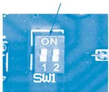
10 DISMANTLING
INSTRUCTIONS RESERVED EXCLUSIVELY FOR QUALIFIED PROFESSIONAL SPECIALISTS
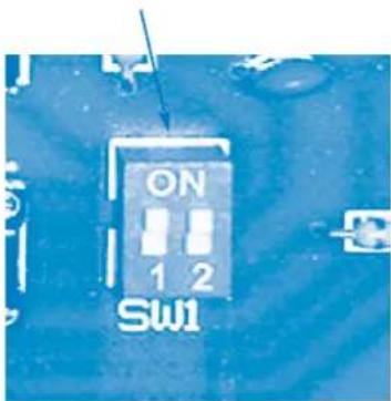
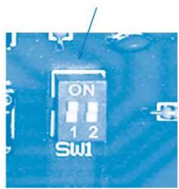
If one of the motors cannot be made to operate correctly, use of that motor can be "disabled" by setting the corresponding switch on the board (SW1: switches 1 and 2 for motors 1 and 2).
text_image
ON 1 2 SW1The motor thus "disabled" can be removed. The unit operates on the other motor.
11 GUARANTEE
2 years guarantee as from its date of purchase subject to correct installation and correct use.
Only the disposal of toilet paper, faecal matter, and waste water will be under guarantee. Any damage due to foreign bodies such as cotton, condoms, sanitary towels, wet wipes, food, hair, metal, wood or plastic objects, will not be under guarantee. Solvents, acids and other chemicals can also cause damage to the unit, and will invalidate the guarantee.
1 BESCHREIBUNG
natural_image
Close-up of electronic components including resistors, capacitors, and a switch (no readable text or symbols)text_image
ON 1 2 SW1natural_image
Close-up of a circuit board with components including resistors, capacitors, and an electronic module (no readable text or symbols)natural_image
Close-up of electronic components including capacitors, resistors, and a switch (no readable text or symbols)text_image
ON 1 2 SW1natural_image
Close-up of electronic components including a microcontroller, capacitors, and a breadboard (no readable text or symbols)text_image
ON 1 2 SW1natural_image
Close-up of electronic components including capacitors, resistors, and a breadboard (no readable text or symbols)text_image
ON 1 2 SW1text_image
SFA Gele LED Voeding Rode LED Alarm Manuele activeringWERKING VAN HET ALARM
1/ Algemene alarmen:
Niveau-alarm:
WERKING VAN HET ALARM
1/ Algemene alarmen:
Niveau-alarm:
7 WERKING VAN DE ALARMUNIT
natural_image
Close-up of electronic components including an integrated circuit, capacitors, and a switch (no readable text or symbols)text_image
ON 1 2 SW1natural_image
Close-up of electronic components including resistors, capacitors, and a switch (no readable text or symbols)text_image
ON 1 2 SW1natural_image
Close-up of electronic components including capacitors, switches, and a blue circuit board (no readable text or symbols)text_image
ON 1 2 SW1natural_image
Electronic circuit components including capacitors, resistors, and a breadboard (no readable text or symbols)8 INSPEKSJON OG VEDLIKEHOLD
1/Inspeksjon
text_image
ON 1 2 SW1Motoren som er «deaktivert» kan da fjernes. Enheten drives med den andre motoren.
11 GARANTI
natural_image
Close-up of electronic components including capacitors, resistors, and a switch (no readable text or symbols)text_image
ON 1 2 SW1natural_image
Close-up of electronic components including capacitors, resistors, and a switch (no readable text or symbols)text_image
ON 1 2 SW1natural_image
Close-up of electronic components including capacitors, switches, and a circuit board (no readable text or symbols)text_image
ON 1 2 SW1natural_image
Close-up of electronic components including capacitors, resistors, and a switch (no readable text or symbols)text_image
ON 1 2 SW1natural_image
Close-up of electronic components including integrated circuits, switches, and a labeled component (no readable text or symbols)text_image
ON 1 2 SW1text_image
SPA RAZ (*): Resetlemenatural_image
Close-up of electronic components including capacitors, resistors, and a switch (no readable text or symbols)text_image
ON 1 2 SW1flowchart
graph TD
    A["Circle"] --> B["Plug icon"]
    C["Circle"] --> D["Warning symbol"]
    E["Circle"] --> F["Warning symbol"]
    G["Circle"] --> H["Warning symbol"]
    I["Circle"] --> J["Warning symbol"]
    K["Circle"] --> L["Warning symbol"]
    M["Circle"] --> N["Warning symbol"]
    O["Circle"] --> P["Warning symbol"]

natural_image
Blank white image with a thin blue border (no text, symbols, or markings)8
9


natural_image
Empty white square with a thin blue border (no text or symbols)7
text_image
156 86 40 86 128 Ø5 Ø5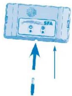
text_image
SFA10
text_image
ON 1 2 Sw111

CN
1

3
4
5

text_image
26
flowchart
graph TD
    A["Plug"] --> B["Block"]
    C["Full"] --> D["Block"]
    E["Wind Turbine"] --> F["Block"]
text_image
SFA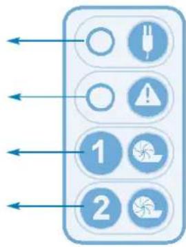
flowchart
graph TD
    A["1"] --> B["2"]
    B --> C["3"]
    C --> D["4"]
    D --> E["5"]
    E --> F["6"]
    F --> G["7"]
    G --> H["8"]
    H --> I["9"]
    I --> J["10"]
    J --> K["11"]
    K --> L["12"]
    L --> M["13"]
    M --> N["14"]
    N --> O["15"]
    O --> P["16"]
    P --> Q["17"]
    Q --> R["18"]
    R --> S["19"]
    S --> T["20"]
7
text_image
156 86 40 86 128 Ø5 Ø5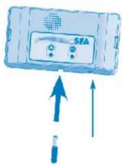
natural_image
Illustration of a SEA device with two buttons and an upward arrow indicating direction (no text or symbols)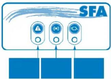
flowchart
graph TD
    A["SFA"] --> B["Warning Icon"]
    A --> C["Warning Icon"]
    A --> D["Warning Icon"]
    B --> E["Input Module"]
    C --> F["Input Module"]
    D --> G["Input Module"]
text_image
Rest Sul1 Sul2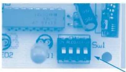
natural_image
Close-up of electronic components including an integrated circuit, switches, and a breadboard (no readable text or symbols)8
9

natural_image
Solid blue rectangular shape with a small triangular icon on the left (no text or symbols)10
text_image
ON 1 2 SW111

1 개요
natural_image
Close-up of a blue electronic component with buttons and a central indicator (no readable text or symbols)text_image
ON 1 2 SW1text_image
9 4 # # # # # # # # # # # # # # # # # #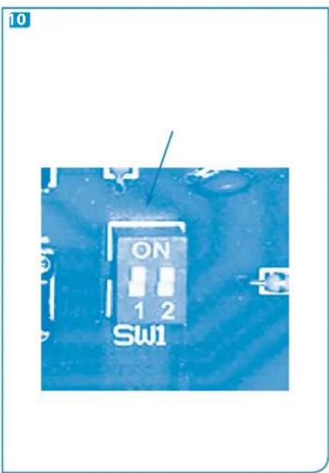
text_image
10 ON 1 2 SW1
natural_image
Simple blue triangular icon on white background, no text or symbols present1 UPOZORENJE
Ova podizna postaja kontinuirano podliježe kontroli kvalitete u tvornici koja ima certifikate ISO 9001, ISO 14001. Pruža visoku razinu učinkovitosti, sigurnosti i pouzdanosti kada se strogo poštuju sva pravila za postavljanje i održavanje opisana u ovoj knjižici.

Ovaj uređaj nije namijenjen osobama (uk-juči djecu) ograničenih tjelesnih, osjetilnih mentalnih sposobnosti ili osobama koje nema-anja i iskustva osim ako nisu pod nadzorom i obivaju potrebne upute za upotrebu uređaja omoć osobe odgovorne za njihovu sigurnost. za moraju biti pod nadzorom kako se ne bi la uređajem.
2 PRIMJENE
Ovaj uređaj je kompaktna podizna postaja. SANICUBIC® 1 i SANICUBIC® 1 WP podizne su postaje posebno razvijene za individualnu upotrebu (kuće ili manji komercijalni lokali).
SANICUBIC® 2 Classic i SANICUBIC® 2 Pro podizne su postaje posebno razvijene za individualnu, komercijalnu i upotrebu u manjim zajednicama (male zgrade, trgovine, javni prostori).
SANICUBIC® 2 XL podizna je postaja posebno izrađena za javnu upotrebu (poslovne zgrade, restorani, tvornička upotreba, škole, hoteli ili trgovački centri).
Ovi uređaji usklađeni su s normom EN 12050-1 (podizne postaje za tekući otpad koji sadrži fekalije) kao i europskim direktivama o građevnim proizvodima, električnoj sigurnosti i elektromagnetskoj kompatibilnosti.
3 INSTALACIJA
Puštanje u rad i održavanje ovog uređaja mora obaviti kvalificirana osoba. Pogledajte normu za instalaciju EN 12056-4.
1 – Oprez: u prostoru u koji će se postaviti uređaj SANICUBIC ^® mora biti najmanje 600 mm radnog prostora oko i iznad uređaja kako bi se olakšalo eventualno održavanje. Taj prostor mora biti svijetao, s dobrom ventilacijom i zaštićen od zamrzavanja.
2- Zaustavni ventili (ne isporučuju se) moraju se postaviti na ulaze odvoda kao i na vod odvoda.
3- Ovaj odvod mora se izvesti tako da se izbjegne povrat iz kanalizacije.
Povrat se izbjegava postavljanjem protupovratne petlje smještene iznad razine povrata.
Napomena: Osim ako lokalni propisi ne odreduju drugačije, razina povrata odgovara razini lokalnih cesta (ceste, pločnici...). Ovaj vod nastavite nakon protupovratne petlje pomoću cijevi većeg promjera.
4- Preporučuje se instalacija pomoćne pumpe za eventualni odvod iz prostora (u slučaju poplave).
5- Podizna postaja mora se odzračivati kroz krov.
ELEKTRIČNO PRIKLJUČIVANJE
natural_image
Close-up of electronic components including capacitors, resistors, and a circuit board (no readable text or symbols)Oprez: kod mora biti isti na obje kartice.
text_image
ON 1 2 SW11/AGEA ENADAR ENGLAME:
مستوى الإندار:
natural_image
Close-up of electronic components including capacitors, resistors, and a Sw1 connector (no readable text or symbols)flowchart
graph TD
    A["LED"] --> B["Warning Icon"]
    C["LED"] --> D["Warning Icon"]
    E["LED"] --> F["Warning Icon"]
    G["LED"] --> H["Warning Icon"]
    I["LED"] --> J["Warning Icon"]
    K["LED"] --> L["Warning Icon"]
    M["LED"] --> N["Warning Icon"]
    O["LED"] --> P["Warning Icon"]
    Q["LED"] --> R["Warning Icon"]
    S["LED"] --> T["Warning Icon"]
    U["LED"] --> V["Warning Icon"]
    W["LED"] --> X["Warning Icon"]
    Y["LED"] --> Z["Warning Icon"]
    AA["LED"] --> AB["Warning Icon"]
    AC["LED"] --> AD["Warning Icon"]
    AE["LED"] --> AF["Warning Icon"]
    AG["LED"] --> AH["Warning Icon"]
    AI["LED"] --> AJ["Warning Icon"]
    AK["LED"] --> AL["Warning Icon"]
    AM["LED"] --> AN["Warning Icon"]
    AO["LED"] --> AP["Warning Icon"]
    AQ["LED"] --> AR["Warning Icon"]
    AS["LED"] --> AT["Warning Icon"]
    AU["LED"] --> AV["Warning Icon"]
    AW["LED"] --> AX["Warning Icon"]
    AY["ABC: LED, RM, A, A', RM, A, RM, A, RM, A, RM, A, RM, A, RM, A, RM, A, RM, A, RM, A, RM, A, RM, A, RM, A, RM, A, RM, A, RM, A, RM, A, RM, A, RM, A, RM, A, RM, A, RM, A, RM, A, RM, A, RM, A, RM, A, RM, A"] --> B
    AC --> AD
    AD --> AE
    AE --> AF
    AF --> AG
    AG --> AH
    AH --> AI
    AI --> AJ
    AJ --> AK
    AK --> AL
    AL --> AM
    AM --> AN
    AN --> AO
    AO --> AP
    AP --> AQ
    AQ --> AR
    AR --> AS
    AS --> AT
    AT --> AU
    AU --> AV
    AV --> AW
    AW --> AX
    AX --> AY
    AY --> AZ
    AZ --> BA
    BA --> BB
    BB --> BC
    BC --> DA
    DA --> AE
    AE --> AF
    AF --> AG
    AG --> AH
    AH --> AI
    AI --> AJ
    AJ --> AK
    AK --> AL
    AL --> AM
    AM --> AN
    AN --> AO
    AO --> AP
    AP --> AQ
    AQ --> AR
    AR --> AS
    AS --> AT
    AT --> AU
    AU --> AV
    AV --> AW
    AW --> AX
    AW --> AY
    AX --> AZ
    AZ --> BA
    BA --> BB
    BB --> AC
    AC --> AD
    AD --> AE
    AE --> AF
    AF --> AG
    AG --> AH
    AH --> AI
    AI --> AJ
    AJ --> AK
    AK --> AL
    AL --> AM
    AM --> AN
    AN --> AO
    AO --> AP
    AP --> AQ
    AQ --> AR
    AR --> AS
    AS --> AT
    AT --> AU
    AU --> AV
    AV --> BW
    BW --> AX
    AX --> AZ
    AZ --> BA
    BA --> BB
    BB --> AC
    AC --> AD
    AD --> AE
text_image
ON 1 2 SW1Howard House, The Runway
South Ruislip Middx.,
HA4 6SE
Tel. +44 208 842 0033/4040
Fax +44 208 842 1671
IRELAND
SANIRISH Ltd
IDA Industrial Estate
Edenderry - County Offaly
Tel. + 353 46 9733 102
Fax + 353 46 97 33 093
AUSTRALIA
Saniflo (Australasia) Pty Ltd
Unit 9-10, 25 Gibbs Street
Chatswood
NSW 2067
Tel. +61 298 826 200
Fax +61 298 826 950
DEUTSCHLAND
SFA SANIBROY GmbH
Waldstr. 23 Geb. B5 - 63128 Dietzenbach
Tel. (060 74) 30928-0
Fax (060 74) 30928-90
ITALIA
SFA ITALIA spa
Via del Benessere, 9
27010 Siziano (PV)
Tel. 03 82 61 81
Fax 03 82 61 8200
SOUTH AFRICA
SFA Africa
www.saniflo.co.za
ESPAÑA
SFA SI
C/ Vinyalets,1 - P.I. Can Vinyalets
08130 Santa Perpètua de Mogoda
Barcelona
Tel. +34 93 544 60 76
Fax +34 93 462 18 96
PORTUGAL
SFA, Lda.
Sintra Business Park, ed. 01-1°P2710-089
SINTRA
Tel. +35 21 911 27 85
Fax. +35 21 957 70 00