Sanicubic 2 Classic Expertline - Sanitary Sanibroyeur - Free user manual and instructions
Find the device manual for free Sanicubic 2 Classic Expertline Sanibroyeur in PDF.
| Product type | Lifting station |
| Brand | Sanibroyeur |
| Model | Sanicubic 2 Classic Expertline |
| Usage | Domestic wastewater evacuation |
| Number of pumps | 2 independent pumps with shredding |
| Max discharge height | 11 m |
| Tank volume | 47 L |
| Maximum absorbed power | 3000 W |
| Supply voltage | 220-240 V |
| Frequency | 50 Hz |
| Maximum current | 13 A |
| Protection rating | IP67 |
| Admissible water temperature | 35 °C continuously, 70 °C intermittently (5 min max) |
| Net weight | 30 kg |
| Electrical class | I |
| Discharge diameter | DN 50 |
| Available inlets | DN40/50 and DN100/110 |
| Alarm | Visual (red LED) and audible (siren) |
| Warranty | 2 years parts and labor |
| Standards | EN 12050-1, European directives |
| Operation | Alternating pumps, simultaneous backup mode in case of fault |
| Maintenance | Monthly visual check, annual check by qualified professional |
| Electrical safety | 30 mA differential circuit breaker, mandatory grounding |
Frequently Asked Questions - Sanicubic 2 Classic Expertline Sanibroyeur
User questions about Sanicubic 2 Classic Expertline Sanibroyeur
0 question about this device. Answer the ones you know or ask your own.
Ask a new question about this device
Download the instructions for your Sanitary in PDF format for free! Find your manual Sanicubic 2 Classic Expertline - Sanibroyeur and take your electronic device back in hand. On this page are published all the documents necessary for the use of your device. Sanicubic 2 Classic Expertline by Sanibroyeur.
USER MANUAL Sanicubic 2 Classic Expertline Sanibroyeur
CONFORMITE AUX NORMES
Fully illustrated step by step instructions are downloadable on www.saniflo.co.uk
DESCRIPTION
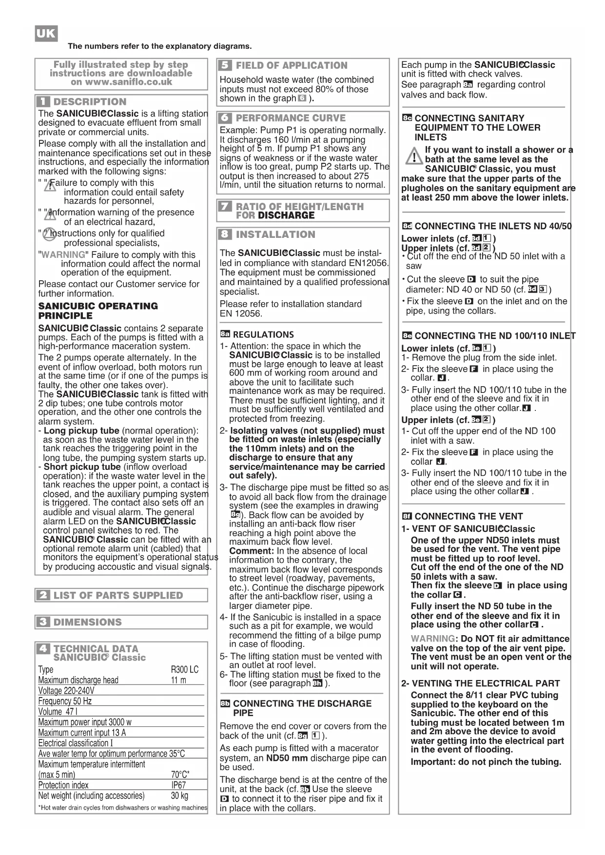
The SANICUBIEClassic is a lifting station designed to evacuate effluent from small private or commercial units.
Please comply with all the installation and maintenance specifications set out in these instructions, and especially the information marked with the following signs:
"Failure to comply with this information could entail safety hazards for personnel,
Information warning of the presence of an electrical hazard,
Instructions only for qualified professional specialists,
"WARNING" Failure to comply with this information could affect the normal operation of the equipment.
Please contact our Customer service for further information.
SANICUBIC OPERATING PRINCIPLE
SANICUBIC Classic contains 2 separate pumps. Each of the pumps is fitted with a high-performance maceration system.
The 2 pumps operate alternately. In the event of inflow overload, both motors run at the same time (or if one of the pumps is faulty, the other one takes over).
The SANICUBICClassic tank is fitted with 2 dip tubes; one tube controls motor operation, and the other one controls the alarm system.
- Long pickup tube (normal operation): as soon as the waste water level in the tank reaches the triggering point in the long tube, the pumping system starts up.
- Short pickup tube (inflow overload operation): if the waste water level in the tank reaches the upper point, a contact is closed, and the auxiliary pumping system is triggered. The contact also sets off an audible and visual alarm. The general alarm LED on the SANICUBIClassic control panel switches to red. The
SANICUBIC Classic can be fitted with an optional remote alarm unit (cabled) that monitors the equipment's operational status by producing acoustic and visual signals.
2 LIST OF PARTS SUPPLIED
DIMENSIONS
4 TECHNICAL DATA SANICUBIO Classic
Type R300 LC Maximum discharge head 11 m Voltage 220-240V
Frequency 50 Hz
Volume 47 I
Maximum power input 3000 w Maximum current input 13 A
Electrical classification I
Ave water temp for optimum performance 35^ Maximum temperature intermittent (max 5 min) 70^^*
Protection Index IP67 Net weight (including accessories) 30 kg
*Hot water drain cycles from dishwashers or washing machines
5 FIELD OF APPLICATION
Household waste water (the combined inputs must not exceed 80% of those shown in the graph 6).
6 PERFORMANCE CURVE
Example: Pump P1 is operating normally. It discharges 160 l/min at a pumping height of 5 m. If pump P1 shows any signs of weakness or if the waste water inflow is too great, pump P2 starts up. The output is then increased to about 275 l/min, until the situation returns to normal.
7 RATIO OF HEIGHT/LENGTH FOR DISCHARGE
8 INSTALLATION
The SANICUBIClassic must be installed in compliance with standard EN12056. The equipment must be commissioned and maintained by a qualified professional specialist.
Please refer to installation standard EN 12056.
REGULATIONS
1- Attention: the space in which the SANICUBIC Classic is to be installed must be large enough to leave at least 600~mm of working room around and above the unit to facilitate such maintenance work as may be required. There must be sufficient lighting, and it must be sufficiently well ventilated and protected from freezing.
2- Isolating valves (not supplied) must be fitted on waste inlets (especially the 110mm inlets) and on the discharge to ensure that any service/maintenance may be carried out safely).
3- The discharge pipe must be fitted so as to avoid all back flow from the drainage system (see the examples in drawing 3). Back flow can be avoided by installing an anti-back flow riser reaching a high point above the maximum back flow level.
Comment: In the absence of local information to the contrary, the maximum back flow level corresponds to street level (roadway, pavements, etc.). Continue the discharge pipework after the anti-backflow riser, using a larger diameter pipe.
4- If the Sanicubic is installed in a space such as a pit for example, we would recommend the fitting of a bilge pump in case of flooding.
5- The lifting station must be vented with an outlet at roof level.
6- The lifting station must be fixed to the floor (see paragraph 3).
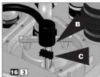
35 CONNECTING THE DISCHARGE PIPE
Remove the end cover or covers from the back of the unit (cf. 391).
As each pump is fitted with a macerator system, an ND50 mm discharge pipe can be used.
The discharge bend is at the centre of the unit, at the back (cf. 35) Use the sleeve to connect it to the riser pipe and fix it in place with the collars.
Each pump in the SANICUBIeClassic unit is fitted with check valves.
See paragraph 3a regarding control valves and back flow.
BC CONNECTING SANITARY EQUIPMENT TO THE LOWER INLETS
If you want to install a shower or a bath at the same level as the SANICUBIC Classic, you must make sure that the upper parts of the plugholes on the sanitary equipment are at least 250~mm above the lower inlets.
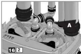
CONNECTING THE INLETS ND 40/50
Lower inlets (cf. 2) Upper inlets (cf. 2)
Cut off the end of the ND 50 inlet with a saw
- Cut the sleeve to suit the pipe diameter: ND 40 or ND 50 (cf. 3d)
Fix the sleeve on the inlet and on the pipe, using the collars.
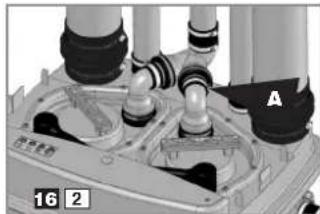
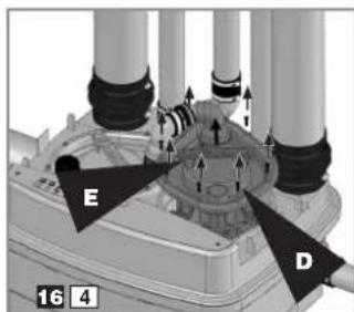
3 CONNECTING THE ND 100/110 INLET
Lower inlets (cf.
1- Remove the plug from the side inlet.
2- Fix the sleeve F in place using the collar. U.
3- Fully insert the ND 100/110 tube in the other end of the sleeve and fix it in place using the other collar.
Upper inlets (cf. 2)
1- Cut off the upper end of the ND 100 inlet with a saw.
2- Fix the sleeve in place using the collar.
3- Fully insert the ND 100/110 tube in the other end of the sleeve and fix it in place using the other collar.
3 CONNECTING THE VENT
1- VENT OF SANICUBIClassic
One of the upper ND50 inlets must be used for the vent. The vent pipe must be fitted up to roof level. Cut off the end of the one of the ND 50 inlets with a saw. Then fix the sleeve in place using the collar
Fully insert the ND 50 tube in the other end of the sleeve and fix it in place using the other collar.
WARNING: Do NOT fit air admittance valve on the top of the air vent pipe. The vent must be an open vent or the unit will not operate.
2-VENTING THE ELECTRICAL PART
Connect the 8/11 clear PVC tubing supplied to the keyboard on the Sanicubic. The other end of this tubing must be located between 1m and 2m above the device to avoid water getting into the electrical part in the event of flooding.
Important: do not pinch the tubing.
89 DRAINING
The SANICUBI®Classic unit is fitted with 2 plugs. Disconnect the unit from the power supply.
To drain the unit
1- Unclip the cover.
2- Remove one of the 2 plugs.
3- Insert a wet utility vacuum cleaner pipe to drain the unit. The port diameter is 40mm
4- When the unit has been drained, put the plug and then the cover back in place.
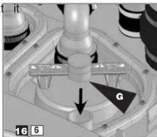
FIXING THE SANICUBIC UNIT TO THE FLOOR
The SANICUBIC Classic unit is equipped with fittings to hold it on the floor and prevent it from turning or moving.
1- Place the unit on the desired spot.
2- Draw the outline of the unit.
3- Position the brackets and fix them to the floor as shown on the template diagram 1
4- Put the unit back in place.
5- Fix the unit in place with the screws.
ELECTRICAL CONNECTIONS
1- The electrical installation work must be carried out by a qualified electrician. The electrical installation must comply with the standards in force in the country concerned
2- The power supply must be of the class 1 type. The unit must be connected via an earthed connection box. The electric power circuit must be protected by a high-sensitivity 30mA differential circuit breaker set at 20A . The connection must be used solely to power the SANICUBIC Classic If the power lead on the unit is damaged, it must be replaced by the manufacturer or its after-sales service to avoid all danger.
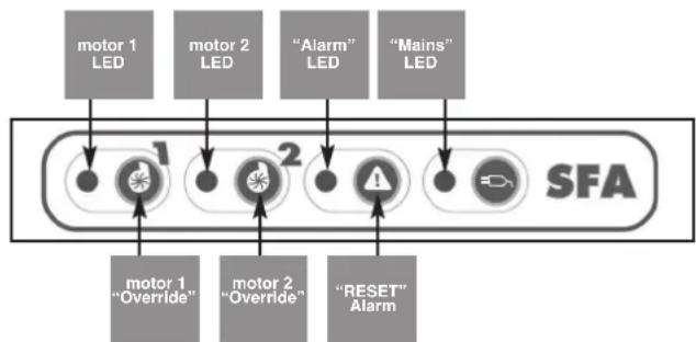
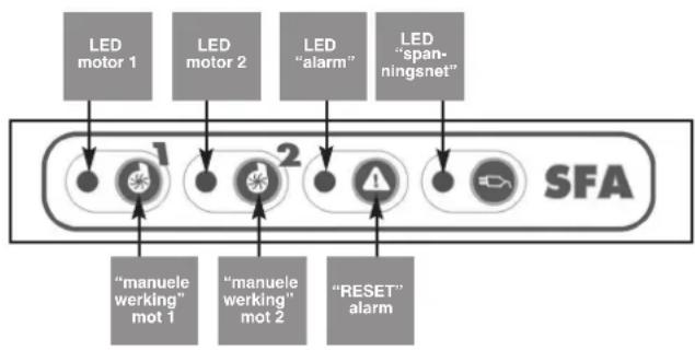
9 ALARM OPERATION
1/ General alarms:
High level alarm:
If the water level in the unit is abnormally high: the buzzer is triggered and the red LED comes on; the other motor starts up 3 seconds later (see the illustration showing the control keyboard).
Temporary alarm:
If one of the 2 motors runs for more than 1 minute: the buzzer is triggered and the red alarm LED comes on; the other motor starts up 3 seconds later.
2/ Resetting the general alarms:
If the problem that has triggered one of the alarms referred to above ceases, the buzzer stops, but the red alarm LED stays on to memorize the fact that the system has met with a problem.
The "Reset alarm" key on the keyboard is used to switch the buzzer off in all cases, but it only switches the red LED off if the problem that triggered the alarm has been dealt with. This avoids the risk of having a system "abandoned" in fault status.
UNIT ALARM
10 CONFORMITY WITH STANDARDS
- SANICUBIC Classic complies with standard EN 12050-1 (lift station for household waste containing faeces) and with the European directives covering construction products, electrical safety and electromagnetic compatibility
This unit must be installed and used in compliance with European installation standard EN12056 and with local requirements.
COMMISSIONING
1- Once the plumbing and electrical connections have been made, check that the connections are watertight by letting water flow successively through each inlet used. Make sure that the unit is operating correctly by carrying out at least two start cycles with water to test the system.
2 - WARNING! Do not operate the motors in override status (by pressing the pushbuttons on the control box) until the pumps have been filled with water. Operation without water damages the maceration system.

USE
1- The SANICUBIC Classic unit is designed to drain off household waste water. Any other use will invalidate the guarantee. Do not dispose of sanitary towels, condoms, hygiene articles, oils, solvents, acids, or any other potentially corrosive or explosive liquids etc., via the unit.
2-WARNING: In the event of a power failure, stop draining any water from the equipment connected to the SANICUBIC® Classic unit.
3- Do not install or use the unit in a zone where there is a risk of explosion.

MAINTENANCE
A visual check of the lift station must be made once a month to make sure it is operating correctly, and the installation must be inspected regularly (once a year) by a qualified person. Meanwhile if encounter technical problems, please ask our after-sales service for advice. If the power supply cable of the unit is damaged, it must be replaced by the manufacturer or its after-sales service to avoid all danger.

GUARANTEE
The SANICUBIC Classic unit is guaranteed for two years (parts and labour) provided that it has been installed and used in compliance with the present instructions.
WORK THAT MAY BE REQUIRED

ELECTRICAL INSTALLATION MUST BE CARROUT BY A PROFESSIONAL ELECTRICIAN

Before carrying out any other types of work, disconnect the Sanicubic Classic from the power supply.
ALARM ON APPLIANCE
First interventions on the appliance
| FAULT | PROBABLE CAUSES | ACTION TO BE TAKEN |
| 1 - Alarm + general alarm LED flashing | ·Faulty detection system | ·Consult the SFA customer services |
| 2 - Alarm + general alarm LED lit | ·Blocked pipe ·Pump blocked or seized | ·Make the pumps work (MO button) in several bursts. ·Consult an SFA approved engineer |
| 3 - general alarm LED | ·The appliance has the following problem: blocked pipe, seized or blocked pump(s) ·The appliance has been affected by a mains power cut | Press on one of the two MO buttons to reset (alarm stops) |
| 4 - Alarm + general alarm LED + yellow mains LED flashing | ·Mains power cut | ·To stop the alarm, press on one of the two MO buttons Check the electrical system ·Consult the SFA customer services |
Second interventions on the appliance
| FAULT | PROBABLE CAUSES | ACTION TO BE TAKEN |
| The motor does not start but the MF works | ·faulty electronic board | ·Consult the SFA customer services |
| Pumps on constantly | ·Outlet pipe blocked ·Discharge head too high ·Faulty detection system ·faulty electronic board | ·Unblock the outlet pipe ·Check the installation (*) ·Consult the SFA customer services |
| Pumps work intermittently | ·Check valves either leak or are broken | Clean or change check valves |
(*) Warning: if pumping height is high, 90^ elbows should be avoided.
MO: Manual Over ride
16 DISMANTLING

INSTRUCTIONS RESERVED EXCLUSIVELY FOR QUALIFIED PROFESSIONAL SPECIALIS
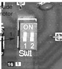
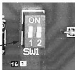
If one of the motors cannot be m to operate correctly, use of that m can be "disabled" by setting the corresponding switch on the board (SW1: switches 1 and 2 for motor and 2).
The motor thus "disabled" can be removed. The unit operates on the other motor.
REMOVING A MOTOR
DISCONNECT THE UNIT FROM THE POWER SUPPLY (the yellow indicator light must be flashing
The unit beeps to show that is no longer under power.
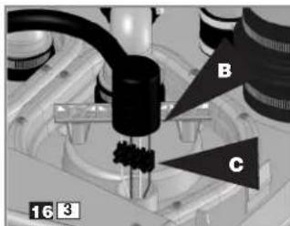
Unclip the cover.
Unscrew the collA on the faulty motor (the check valve stays in place while the mot is being repaired).
Put the inspection cover back in place.
Reconnect the discharge pipe. Use the plug to close off the motor cable outlet in the inspection cover. Fix using the hose cliB
Unscrew the collB. Remove the motor power wires Cbm the screw connector.
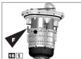
Operations on the electronic board (cf. illustratid61): set the switch corresponding to the number of the faulty motor from ON to OFF:
1 = motor 1
2 = motor 2
In this configuration, the unit will not switch to "alarm" status and the electronic board only powers the motor remaining in place.
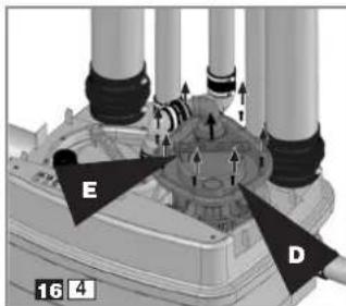
PUTTING THE MOTOR BACK IN PLACE
Remove the plu and the inspection cover.
Screw the motor onto the inspection cover and put the cover back in place.
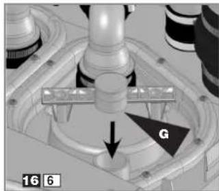
Reconnect the motor power wires (cf. illustration63).
Warning:
Comply carefully with the colour code:
Blue wire with the blue wire Brown wire with the brown wire
Green wire with the green wire
White wire with the white wire
Set the motor switch on the board to ON.
Reconnect the discharge pipe.
Connect the unit to the power supply.
Carry out a complete test for commissioning (cf. paragraph 1).
T BESCHREIBUNG
LIGACAO DA EVACUACAO
9 WERKING VAN HET ALARM
1/ Hoofdalarmen:
ALARM VAN HET APPARAAT
10 NORMEN
ALARM OP HET APPARAAT
Nominell effect max 3000 W
"HCTpyKUIN, INpeHa3HaueHHbIe NCKJIIOUHTeJIbHO IJI KBAJIINΦUINPObaHHbIX CNEUJANCTOB,
"BHHMAHNE" - yka3aHne, HecobIOJeHne KOtOpO MOxET npBecTn K HeCnpaBHOCTN B pa6oTe YCTaHOBKN.
3a dononHnTeBHOH nHΦopMaueNei npocm obaaatbC B cnjx6y no pa6oTe C KIneHTamn. TeJ. (495) 258 29 51
PINHcPi PABOTbI
SANICUBIClassic cha6xeh 2 He3aBnCmblIMN pOMpAMn. KaKdaH N3 HIX OCHaSeHa BbICOKOpON3BOIDNTeHbHO CNTeMOI N3MeJIbYeHr.
KaJdaI3 NOM pa6oTaET He3aBnCmOBpeKIMe UpeEIOBaHn. B cnyuaeBO3HKnHOBeHHA HOMAniPi pa6oTeyCTaHOBKn NOMbI HaunHaOT pa6oTaTbOHDOBPeMeHHO (HIN, ECIN OHa N3 POMNHeNCnPpABHa, ABtOMaTIueeCKn BKIIIOaETCBTOpa).
Kopnyc yctaHOBN SANICUBIoclassic Ochauen 2 PnHyXepHbIM Tpy6amN, Onda n3 KOTOpbIX ynpabnre patBOToMOTopoB, aDpyra-CNTeMOINrHaJIIN3aUN.
-Диннога пунжерна Тура (HOPмальньп реким pa60ты): кAK TOЛьКО CTOKI DOCTRAHOT YPOBHA BKПIOЧЕНЯ B ДИИНHOI TPy6e, BKJIIOHaTeCn CnTeMa NepeKaUKN.
Kopotka npyHxepHa Tpy6a (ahOMaJIr):ecNI CTOKN DoCTnraOT BepxHrO yPOBnB V KOpnyce, ABTomatneCKN BKIIIOuAETcN abapinHaN CnCTeMa DOnoINHTeNbHOI nepeKaUKN 3ByKOBOI INCBETOBON cInHaIN3aUN. 3axnraETcKpachbI INHdNKaTOp OObuei CNrHAIN3aUN Ha KlaBNAtype SANICUBICIscic. SANICUBICIscic MoKeT 6bITb OChauEN DOOnOIHTeNbHOI PNOBOHDON dNCTaHNUHOH CNrHAIN3aUNe (ONuN), BOCPON3BOJAAeIe ONTNueckNe I 3ByKOBbI cINHaJIb paobToI annapata.
CNICOKIOCTABJREMBIX DETAJEN
3 PA3MEPbl
4 TEXHnueCKNE DAHHbIE SANICUBIC Classic
| Tin R300 LC | |
| Makcimba Nha BepTKaIbHa | |
| OTkaUka | 11 M |
| HapraJKeHne | 220-240B |
| Qactota | 50 Tc |
| O6bEm | 47 n |
| Makc. NotpebIeMaM aouHocTb | 3000 BT |
| Makc. NotpebIeM bI ToK | 13 A |
| ÖlektreCheckm Klaacc | I |
| CpeHnA DonyctHmAg | |
| TempepaTpya BODbl | 35°C |
| Makcimba Nha TempepaTpya | |
| c nepepbIbAmi (He 6oJee 5 MnH) | 70°C* |
| INHeKc 3aunTbI | IP67 |
| Bec HETTO (BKNUOaA akCEccyapbl) | 30 Kr |
5 OBJACTb IPIIMEHEHNA
ДпЯ OTBODa CTOHbIX BOI He6OJIbWOrO DOMA (OBsII OБьEM NOCTynAOUIX B YCTAHOBKY CTOKOB He DOnJKeH NpeBbIaTb 80% npOn3BOdNTeNbHOCTn, yKa3aHHoHa rpaФIKE
6 TPAΦNK IPOU3BOIDHTbHOCTu
PnpMep: Hacoc P1 pa6oTaET HopMaIbHo.
Pn noDbem Ha 5 M OH OTKaunBaET CO CKOpocTbIO 160 n/MnH. B cnyae ecnn
Hacoc P1 He cnpabNareTcH nnecn CnIuKOM 3NaHTeJbHbI O6bEM
OTpa6oTahHO BObl, BKIOUaetcH Hacoc P2. B 3Tom cnYae ckOpocTb nepekaKn IOdHMmaTeCn, pnp6nIN3TEJbHo, Do 275 n/MnH Do HopMaIn3aun.
7 COOTHOWEHNE BbICOTbl N DLIINbI OTKAUYBAHNR
8 YCTAHOBKA
YctaHOky CnCTeMbI SANICUBlClcI sCneJeT OcyuEcTBnAryb C yyeTOM HOpMbEN12056.BBoD B3KcNpyatauHIO nTexHueckoe 06cnyxNBAHne DaHHOyCTaHOKN DOJXhbl 6bITb OcyuEcTBnEhblKBaINΦnIPoBaHHbIM CneUmaJIncTOM.
OB3ATEJIbHbIE YCIOBUNI3 HCHTPYKUIN
1-BHIMAHHe:IOcO6Hoe NOMEseHne,B KOtOpOM 6yDet yCTaHOBJIeHa CnCTema SANICUBIClassic,DOJXHo 06IaTb IOCTaTOCHbIMpa3MePamn DnI OBeCNEeHHN HeOxOIMOr pa6OoTe IPOCTPAHCTBa (MHNUMym, 600 MM BOKpyr yCTaHOBKn Ha,I He) DnI O6JIeYEHN DOCTyna Ha Cnyauh OeOxOIMOCTN TexNIeCKOrO 06CNYINBAHm. 3TO NOMEseHne DOnKHO 6bITb XopoO OcBeueHo n PpOBETPMBaEMo,A TaKxe 3aUInHeo OT 3aToPJIeHHN 3aMEp3AHn.
2-3anophbe BENTHIN (He BXOJATB KOMNJIeKT NOCTABKN) CNEyET YCTaHOBNTb Ha BXODe CTOKOB, a TaKKe Ha Tpy6oPpOBoDE OTKaUHBaHH.
3- Tpy6onpoBOd OTKaUHbAHn DOJXKeH npoxoNTb TaKIM 06pa3OM, YTO6bl N36ExaTb KaKOrO 6bl TO HN 6blIO OTtOKa N3 KaHaJIIN3aUN. OTtOKa MOxHO N36ExaTb, CMOHTnpoBaB NetTIIO BbIe yPOBnKaHaJIIN3aUN (CM. nPImepbHa pnc. 3g
PpOOnKnTb Tpy6oPoBOD nocne neTn, nCNoIb3yra Tpy6y 6oNbJero dnaMeTpa.
3ameaHne: kPOME cnyaeb, KOrda SANCUBIC yCTaHOBnEn BbIe yPOBb BXoDa BA KaHaNImaHIO.
4-MbI peKOMeHdyem yCTaHOBnTb DOnOJIHHTeJIbHyIO NOMNy DInJ B03MOXHORo DpeHaxKa NoDCO6HOrO NOMeueHH (B CNYae 3aTOITNeHH).
5-Cntema BHTnIaun CTaHUN nepepaotkn DOJXHa HaxoDnTbcra NpKpbIwei.
6-CTaHnO TKAuNbA Hn JOnJHa 6bTb 3aKpeNHe Ha 3emne (cm. naparpaΦ 3h).
85 NOIDCOEINHEHNEKCTOKY
CHNMMTe 3aIpyuKn Ha 3aIHei Yactn yCTaHOBKn (CM.31
BnaOapr TOMy,TO Ha KaKdoi NOMne yCTaHOJIeHa CnCTema N3MeJbYeHnIOCTaTOUHO NcONJb3OBAbT Tpy6OpBODoOTKaUNBaHHN DnAmETpOM 50 MM.
IaTpy6OK OTKaUHbHnHaXoDntcB 电HTpaJIbHOu YAcTHyCtAHOBKn, C3aDN (CM.35C NOMOUsbMyΦTbI COeINHnTe erO C BepTnKaJIbHOu Tpy6oJ DnIaOTKaUHbHnN 3aKpEnITe XOMYtAMN
KaJdaI NOMa yCTaHOBKn
SANICUBIIClassic yxe obopydoBaHa o6paTHbIM KJIaNaHOM.
CM. INHOpMaUIO O BEHTUNJx N OTTOKBy naparpaede 3a
IOKJIIOUeyHNECAHTEXHNI K HIXHM BXODAM
EcnBbXOTnTe yCTaHOBTb !yW nnn BaHHyo Ha TOM Ke ypoBHe,HTO N CNTeMy
SANICUBIClassic, Heo6xOdmo CJeDnTb 3a TeM, YTo6bI BepXHra YacTb BblBOhBix OTBepCTm HaxOduNlac Ha Bbcote, KAK MmHmym, 250 MM.
30 NOCDCOEINHEHNE K BXODAM DNAM.40/50 MM
HxKHe BXOaBi (CM.3d1
BepxHne BxoDbI (cm.32 2
C NOMOJIbIO NINbI cpeXbTe 3aRnykky BXOda dnaMaTePOM 50 MM.
- OTPexbTe MycTy COOTBeTCTBUN CnAmETpOM Tpy6bl:40nn50MM (CM. 3d3)
YCTaHOBnTe MyD TyDa BxOe Ha Tpy6e C NOMOuHbXOMyTOB.
30 NOIDCOEINHEHNE KO BXODAM DNAM.100/110 MM
HnKHe BXOaBi (CM.8e1
1-1-CHMNTe 3aInykky60KOBORBXOda.
2-3akpennte MyfTy FomyTom .
3-BcTaBbTe Tpy6ky DnAmEtPom 100/110 MM B DpyroKoHEuC MyDtbI N 3aKpeNITe DpyTMM XOMYTOM
BepxHne BxoOdbi (cm.3p 2
1-CnOmoUbIO NIIbI cpeXbTe 3aRnyuKy BXoJa DnAmEtPOM 100 MM.
2-3akpenTe MyfTy pni nOmoXomYTa
3 - BctaBbTe Tpy6ky dnaMetpom 100/110 B DpyroKoHeu MyOtbl N3aKpeNITe ee DpyrIM XOMYTOM
NODCOEDHHEHNEKBEHTNJAQUIN
1- BEHTNJALUNI SANICUBIClassic
OJHO n3 BepxHnBxOoHbIX OTBepCTn DnaMeTpom 50 MM CneDyET NcNOB3OBaTb DJI BEHTNJAUIN.
BeHTnIaHOnHa Tpy6a DoJnxHa BbIXoNtB Ha KpbIy. C NOMOsbIO NINbI CpeXbTe 3aRnyuKy OdHoro n3 BXoDOb dAmetpom 50 MM.
3aTeM 3aKpeNITe MyOXYOMCTaBbTe Tpy6ky DnAmETpOM 50 MM BdpYroN KOHeu MyOHTbI N 3aKpeNITe dpyrMM XOMYOM
BHIMAHHE:He cneJeYET NOcOeHnHTb yCTpOncTBO dNCHATNA BAKyyMa K OTBepCTnIO BEHTNJRAUHOHNOHTOpy6bl-OHO DOJNXHO OCTaBaTbCRA OTKpbITbIM DnO ObecNeueHnnpabunbHo pa60tby YCTaHOBKn.
2-ПОДУВКА 3ЛЕКТРИСЕСКOrOБLOKA:
CoeHnHtBtp6Ky 8/11, BxOaHuyo B KOMnIeK T yCTaHOBKn, C nylbTom Ha sanicubic (cm. cxemy 123). BToPoN KOHeU Tpy6Kn DoJXeH pacNoJaTaBcR HaD yCTaHOBkoHa BBicote OT 1 do 2 M, TaK YTObI B cNyuae 3aTOnJIeHHBa He Morna nonactb B 3JeKTPnueckn 6JOK.
BHHMaHHe: He npokalbIbAtb Tpy6ky.
39 DPEHAXHbIE OTBEPCTNA
YcTaHOBka SANICUBIECClassic chabxkeHa 2 3arJyUkAm371OTKnIOHTb 3JeKtpnueckoe NITaHne yCTaHOBKn.
YtobIOnopoxKHTb yCTaHOBky:
1- CHIMMTE 3aXkMbI KpbIuKN.
2-BbInbTe 1 n3 2 3aŋnyweK.
3-IVcnoIb3yIte DOnoJIHInTeIbHbI HAcOC dNtOKaUHBAHn BOIbI N3 KOpNyCa yCTAHOBKn (DnaMeTp OTBepCTIN COCTABJAE40 MM).
3aKoHnB ONOpOxHeHne, BHOb yCTaHOBnTe Ha MeCTo 3aJIyUkY, a 3aTEM KpbIuKy.
3 KPNJIeHNE KOPNYCA K NOJY
YTo6bI yCTaHOBka SANICUBlEClassic cTOrna npOHy n HenoDbVnKHO, OHa OChaueHa DeTaJIaMn KpeNJIeHn K NOy.
1- NoCTaBbTe yCtAHOBky Ha HameyehHOe MeCTO.
2-ObBeDInTe KOHTyp yCTaHOBKn.
3-YcTaHOBnTe yroJbHnKn npNKpePnTe nx K noLy B COOTBETCTBn C nlaHOM CBepJeHnA OTBepCTn 361
4-YctahOBtE Detajn KpenJIeHnI.
5-3aKpeHnTe ycTaHOBky C nOMOuIb BO BnHTOB
3JIEKTPONOOKJIOUOHEHNE
1-3NeKtpoNoDKIIOueHne DOJXHO 6bITb OcyuieCTBNEHO KBaINnPnIPOBaHHbIM 3JeKtpNKOM.3NeKtpnoDknIOueHne DOJXHO COOTBeTCTBOBaTb HOpMaM, pInHrTbIM B CTPaHe NOTpe6nte Ira aHaIoNHybIX 3NeKtpOnpnpopob.
2-3NeKTPoNOJIKIIOHHe NDOJXHO COOTBeTCTBOBaTb KNaCCy 1. YCTaHOBKa DOJXHa 6bITb NOJKNIOUeHa K 3a3EMJIeHHO CoEINHTeHOB HOKOPo6Ke.3NEKTPuueckA JINHNA DOnJXHa 6bITb 3aUNIeHa BBICOKOuyBCTBNTeHBIM AnpepeHuaNbHBIM BbIKNoHTeJeHem Ha 30 mA c npedoxpaHnteMe 20 A. DaHHa 3NEKTPuuecka JINHNA DOJXHa NCNOJb3OBAtbcra ToNbKO dIINITAHN yCTaHOBKn SANICUBRClassic. B Cnayae nobpekdeHn Ka6enla yCTaHOBKn erO cneYet 3AmEHt b y pON3BOIInTeJn Nn B erO cepBcHbIX cHTpax, BO n36ExaHHe pCKaKnx 6bl TO HN bblno NobpeKDeHN.
CINHAIIN3ALIIN

DAHHbIE INHCTPYKcIM INPEdHA3HAcEHbI NCKJIIOUHTeJIbHO IJI KBAJIINΦUPOBAHHbIX CNEUJNCTOB
1/067aCnHaJn3aun
CnHaJIIm3aUNypoBHA:
EcIn ypoBHeB BOdbi BHyTpnyCTaHOBKn CnIWKOM BbICOKN, BKJIIOUHTcR 3ByKObae CNHaIN3aun + 3arOpNTcKpaCHbI INHdNKATop +Yepe3 3cekyHdbi BKJIIOUHTcR BTOpar NOMNa (CM. CXemy nylbTa ynpabNeHH).
TaMep-CnHann3aunr:
Ecnn Odnn n3 DByx MOTOPB pa6oTaet 60nbwe 1 MNHyTbI, BKIOOHNTc3 BYKOBAR CNHAN3aUN + 3arOpNTcKpaChbIM INHINKAtop +Yepe3 3 cekyHdbi BKIOOHNTc2-IMOTop.
ABAPINHbIN CnHAI HA YCTPOIcTBE
OCHOBHbIe BO3MOXHbIe HEnCnpaBHOCTMaunHbI
DpyrRe BO3MOXKhbIe HEnCnpaBHOCTN
| HEUNCIPABHOCTb | BO3MOXHbIE ПИЧИНБI | СПОСБЛВ YCTPAHEHЯ |
| HacocbI pyckaOTcT TOnbKO B PpInHydntelbHom peKHMe | ·HeucnpaBHoCmb элкmpoHnO kapMbI | ·ОратчыВ Сервсну СужБу SFА |
| HacocbI He BvIKlNoAOTcR | ·Зabma Hanopnag MaZuCm- paMbI ·HedonycMumar BlyComa noAbema ·HeucnpaBHa CusCmema pycka ·HeucnpaBHa элкmpoHnAra kapMa | ·Почuctмь МагИстрь. ·Поверпь COOTВETCTBVE МоТаха pyHKtAm ИСТурКУМ ·ОратчыВ Сервсну СужБу SFА |
(1) BHUMOHue! Ppu anoBede Ha 3HauumenbHy oBcmy, yon uZuio pMy He Meee 90.
IX: npunoumennbHu xO
DEMOHTAX MOTOPA
OTKIOUHTE YCTAHOBKY OT 3JEKTPOCETN (KeNTbI INHAnKaTOp DOJXeH NORaChyTb).
Bby ycnblIwnte rydoK, KOTO-pbIn 06o3Haayet, YTO nITaHne yCTAHOBKn OTKJIIOUcHo.
CHaTb 3aXIMbl c KpbIuKN MoTopa. BbIBHnTb KOJIbA HeuCnpaBHorO MoTopa (o6paTHbI KnAnaH DoJKeH OCTaBaTbCra Ha MeCe B XOJe NOUHNK MoTopa).
BbINHTb KONbC B OTKnOHTb npoBOa MOTopa O IIOCTPOBOrO 3aJIMc
BbIBHTNTb BINTbDIOKA. OctopoxHO NOHHTb MOTOP C NOMOsbIpyKoRTKVE
Ecnn HeucnpabHbI MoTOp CnEpyet OtnpaBntb npOn3BOaNTeIO, yCTaHOBka MOKeT pOIOJIKA Tb BblONHHTb MNHmMaIbHbIe fYHKcN C OdHM MOTOpOM. BbIBuHTNTb BNHT HeucnpabHoro MoTopa N3 JIOKa.
BHOBB yCTaHOBNb IIOK.
BHOBB NODKNIOHTb OTBOJ.
C NOMOUBI npo6k
IpekepbITb BbIXOJ npoBOOB
MOTOPa IV3 IIOKA. 3aKpeINTB C
NOMOUBI XOMyTaB
Pa6oTa C 3NeKtpoHHo KaPToI (CM.PnC.1
yctaHOBtTe BbIKJHouateIb
OCTaBWeOcR MoTopa B
noLoXeHne ON, a
HeNCnpaBHOro MoTopa - B
noLoXeHne OFF. 3To no3BOInr
n36ExKaTb BKIOUChEHH
CnHaJIIN3aUIM yCTaHOBKn, a
3JIeKTPoHHa KapTa 6yJeT
NoDaBaTb NITaHne TOnbKO
OCTaBWeMycr MoTopy.
IIOBTOPHAR C6OPKA MOTOPA
BbHyTb npo6Ky ⅢOK.
BHOBB HABINHTb MOTOp Ha IIOK
N yCTaHOBTb IIOK.
BHOBB NODKNIOHTb npOBOa
MOTopa (CM.Pn16)3
OcToPOxHo: CnEInTe 3a UBeTOBbIMN O6o3HaueHnMIM: CNHn IpoBOd CneDyET IOKJIIOuHTb K CnHEMy npOBody
KopnueBbl npoBOc cneDyET
NoKJIIOuHTb K KopnueHOBMy
npoBOdy
3eNeBb npoBOd cneDyET
NoKJIIOuHTb K 3eNeHOMy
npoBOdy
6enb npoBOD cneyet noKIOUHTb K 6eNOMy npoBody.
Npectabntb nepeKIOUaTeIb
kapTb MoToPA B N03nIIO ON.
BHOBB NOdKIOUHTb OTBOID.
PiOKIOUHTb 3JIeKTPoINtAHne.
BHOBB OcyueCTBNTb NOnHoe
NCNbIbTAHne nepeB BBOOM
B E KcNlPyTaUIO (CM. naparpaΦ I).

PA360PKA

DAHHBIE INCHTPKUMN INPEDAHA3HAYEHBINCKKIOYNTELBO KBAJNUCUPOBAHBbIXCNUEMAJNCTOB
Ecnn OdnH n3 MOTOPOB He pa6oTaet npedyCMOTpeHHbIM 06pa3OM,ero NcNoB3OBAHHe MOxHO Jea3AaTHBnPOBaTb》C NOMOuB COOTBeTCTByIOeRO BbIKNouaTeNa, paCNOJoxEHORo Ha KapTe (BbIKNouaTeNb 1 dna Motopa 1 N BbIKNouaTeNb2 dna Motopa 2).
《ДeзаКТИВИРОВАнБИ》MOTOPMOXHCHaTb.YCTaHOBKa6yTePa6OtaTbHaOCTaBWeMcMOTOpe.
DESCRIEREAPRODUSULUI
SANICUBIC Classic this o statie de pompare pe verticala, conceputa pentru evacuarea efluentilor menajeri proveniti de la o casa sau de la un mic spatiu commercial.
Each marked cable lug must be isolated (7, 8, 9 and 10)
SANIFLO Ltd. Howard House,
the railway South Ruislip
the railway South Ruislip
Middx, HA4.6.SF
Middx, HA4.6.SF
Tel: 020 8842 0033 71 Fax: 020 8842 1671
Tel: 020 8842 0033 71 Fax: 020 8842 1671
Middx, HA4.6.SF
Middx, HA4.6.SF
| TEL FAX | ||
| France 03 44 94 46 19 | N°Azur 0810 05 90 02 | 1 UT par appel |
| United Kingdom 08457 650011 (Call from a land line) 020 8842 1671 | ||
| Ireland 1850 23 24 25 (LOW CALL) +353 46 97 33 093 | ||
| Australia +61 3 9543 3891 | +61 3 9543 6851 | |
| Deutschland | 0800 82 27 82 0 | (060 74) 30928-90 |
| Italia | 0382 6181 | +39 0382 618200 |
| Espana | +34 93 544 60 76 +34 93 462 18 96 | |
| Portugal | +351 21 350 70 00 | +351 21 957 70 00 |
| Suisse Schweiz Swizzera | +41 44 748 17 44 | +41 44 748 17 43 |
| Benelux | +31 475 487100 | +31 475 486515 |
| Sverige | 08-744 15 18 | 08-744 15 18 |
| Polska | (+4822) 732 00 33 | (+4822) 751 35 16 |
| Rocsnja | (495) 258 29 51 | (495) 258 29 51 |
| Česká Republika | +420 266 712 855 | +420 266 712 856 |
| România | +40 256 245 092 | +40 256 245 029 |
| 中国 +0574 - 8817 1777 | +0574 - 8728 1907 | |
SERVICE HELPLINES
SER
SER
m - 1 0 ;
| FRANCE SOCIÉTE FRANÇAISE D'ASSAINISSEMENT 8, rue d'Aboukir 75002 Paris Tel. 01 44 82 39 00 Fax 01 44 82 39 01 | ITALIA SFA ITALIA spa Via del Benessere, 9 27010 Siziano (PV) Tel. 03 82 61 81 Fax 03 82 61 8200 |
| UNITED KINGDOM SANIFLO Ltd., Howard House, The Runway South Ruislip Middx., HA4 6 SE Tel. 020 8842 0033 / 4040 Fax 020 8842 1671 | ESPANIA GRUPO SFA C/ Vinyalets, 1 P.I. Can Vinyalets 08130 Sta. Perpètua de Mogoda - Barcelona Tel. +34 93 544 60 76 Fax +34 93 462 18 96 |
| IRELAND SANIRISH Ltd. IDA Industrial Estate Edenderry County Offaly Tel. + 353 46 9733 102 Fax + 353 46 97 33 093 | PORTUGAL SFA Lda Av 5 de Outubro, 10 -1° 1050-056 Lisboa Tel. +351 21 350 70 00 Fax +351 21 957 70 00 |
| AUSTRALIA SANIFLO AUSTRALIA Unit 7, 15 Howleys Road, Notting Hill P.O. Box 5122 Pinewood Victoria 3149 Melbourne Tel. +61 3 9543 3891 Fax +61 3 9543 6851 | SUSSE SCHWEIZ SWITZERIA SFA SANIBROY AB SWITZERLAND Stettenstrasse 6 CH-8954 Geroldswil Tel. +41 44 748 17 44 Fax +41 44 748 17 43 |
| DEUTSCHLAND SFA SANIBROY GmbH Waldstr. 23 Geb. B5 63128 Dietzenbach Tel. (060 74) 30928-0 Fax (060 74) 30928-90 | BENELUX SFA BENELUX B.V. Voltaweg 4 6101 XK Echt Tel. +31 475 487100 Fax +31 475 486515 |