Sanicubic 2 Pro Expertline - Sanitary Sanibroyeur - Free user manual and instructions
Find the device manual for free Sanicubic 2 Pro Expertline Sanibroyeur in PDF.
User questions about Sanicubic 2 Pro Expertline Sanibroyeur
0 question about this device. Answer the ones you know or ask your own.
Ask a new question about this device
Download the instructions for your Sanitary in PDF format for free! Find your manual Sanicubic 2 Pro Expertline - Sanibroyeur and take your electronic device back in hand. On this page are published all the documents necessary for the use of your device. Sanicubic 2 Pro Expertline by Sanibroyeur.
USER MANUAL Sanicubic 2 Pro Expertline Sanibroyeur
10 CONFORMITE AUX NORMES
Fully illustrated step by step instructions are downloadable on www.saniflo.co.uk
DESCRIPTION
The SANICUBIC® 2 Pro is a lifting station designed to evacuate effluent from small private or commercial units.
Please comply with all the installation and maintenance specifications set out in these instructions, and especially the information marked with the following signs:
Failure to comply with this information could entail safety hazards for personnel,
Information warning of the presence of an electrical hazard,
Instructions only for qualified professional specialists,
WARNING" Failure to comply with this information could affect the normal operation of the equipment.
Please contact our Customer service for further information.
SANICUBIC OPERATING PRINCIPLE
SANICUBIC® 2 Pro contains 2 separate pumps. Each of the pumps is fitted with a high-performance maceration system.
The 2 pumps operate alternately. In the event of inflow overload, both motors run at the same time (or if one of the pumps is faulty, the other one takes over).
The SANICUBIC 2 Pro tank is fitted with 2 dip tubes; one tube controls motor operation, and the other one controls the alarm system.
- Long pickup tube (normal operation): as soon as the waste water level in the tank reaches the triggering point in the long tube, the pumping system starts up.
- Short pickup tube (inflow overload operation): if the waste water level in the tank reaches the upper point, a contact is closed, and the auxiliary pumping system is triggered. The contact also sets off an audible and visual alarm. The general alarm LED on the SANICUBIC® 2 Pro control panel switches to red. The system sends a high-frequency malfunction signal to the remote alarm unit. The SANICUBIC® 2 Pro is fitted with a remote alarm module that transmits a visible and audible alarm (HF link).
LIST OF PARTS SUPPLIED
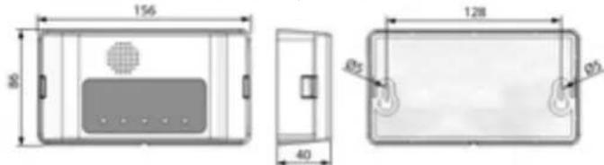
3 DIMENSIONS
4 TECHNICAL DATA SANICUBIC® 2 Pro
Type R300
Maximum discharge head 11 m
Voltage 220-240V
Frequency 50
Volume 471
Maximum power input 3000 w
Maximum current input 13 A
Electrical classification I
Ave water temp for optimum performance 35^
Maximum temperature (intermittent) 70^^*
Protection index IP67
Net weight (including accessories) 30kg
Hot water drain cycles from dishwashers or washing machines
5 FIELD OF APPLICATION
Household waste water (the combined inputs must not exceed 80% of those shown in the graph 6).
6 PERFORMANCE CURVE
Example: Pump P1 is operating normally. It discharges 160 l/min at a pumping height of 5 m. If pump P1 shows any signs of weakness or if the waste water inflow is too great, pump P2 starts up. The output is then increased to about 275 l/min, until the situation returns to normal.
7 RATIO OF HEIGHT/LENGTH FOR DISCHARGE
8 INSTALLATION
The SANICUBIC® 2 Pro must be installed in compliance with standard EN12056. The equipment must be commissioned and maintained by a qualified professional specialist.
Please refer to installation standard EN 12056.
3a REGULATIONS
1- Attention: the space in which the SANICUBIC 2 Pro is to be installed must be large enough to leave at least 600~mm of working room around and above the unit to facilitate such maintenance work as may be required. There must be sufficient lighting, and it must be sufficiently well ventilated and protected from freezing.
2- Isolating valves (not supplied) must be fitted on waste inlets (especially the 110mm inlets) and on the discharge to ensure that any service/maintenance may be carried out safely).
3- The discharge pipe must be fitted so as to avoid all back flow from the drainage system (see the examples in drawing 3a). Back flow can be avoided by installing an anti-back flow riser reaching a high point above the maximum back flow level.
Comment: In the absence of local information to the contrary, the maximum back flow level corresponds to street level (roadway, pavements, etc.). Continue the discharge pipework after the anti-backflow riser, using a larger diameter pipe.
4- If the SANICUBIC is installed in a space such as a pit for example, we would recommend the fitting of a bilge pump in case of flooding.
5- The lifting station must be vented with an outlet at roof level.
6- The lifting station must be fixed to the floor (see paragraph 3h).
35 CONNECTING THE DISCHARGE PIPE
Remove the end cover or covers from the back of the unit (cf. 391).
As each pump is fitted with a macerator system, an ND50 mm discharge pipe can be used.
The discharge bend is at the centre of the unit, at the back (cf. 3b). Use the sleeve to connect it to the riser pipe and fix it in place with the collars.
Each pump in the SANICUBIC 2 Pro unit is fitted with check valves.
See paragraph 3 regarding control valves and back flow.
3 CONNECTING SANITARY EQUIPMENT TO THE LOWER INLETS
If you want to install a shower or a bath at the same level as the SANICUBIC® 2 Pro, you must
make sure that the upper parts of the plugholes on the sanitary equipment are at least 250mm above the lower inlets.
CONNECTING THE INLETS ND 40/50
Lower inlets (cf. 3d1)
Upper inlets (cf. 3d2)
- Cut off the end of the ND 50 inlet with a saw
Cut the sleeve to suit the pipe diameter: ND 40 or ND 50 (cf. 3d3)
Fix the sleeve on the inlet and on the pipe, using the collars.
3 CONNECTING THE ND 100/110 INLET
Lower inlets (cf. 3a1)
1- Remove the plug from the side inlet.
2- Fix the sleeve in place using the collar
3- Fully insert the ND 100/110 tube in the other end of the sleeve and fix it in place using the other collar
Upper inlets (cf. 2)
1- Cut off the upper end of the ND 100 inlet with a saw.
2- Fix the sleeve in place using the collar
3- Fully insert the ND 100/110 tube in the other end of the sleeve and fix it in place using the other collar
3 CONNECTING THE VENT
The SANICUBIC®2 Pro must be vented with an outlet at roof level.
Fix the sleeve D in place using the collar C
Fully insert the ND 50 tube in the other end of the sleeve and fix it in place using the other collar
WARNING: Do NOT fit air admittance valve on the top of the air vent pipe. The vent must be an open vent or the unit will not operate.
Fixing The SANICUBIC UNIT TO THE FLOOR
The SANICUBIC 2 Pro unit is equipped with fittings to hold it on the floor and prevent it from turning or moving.
1- Place the unit on the desired spot.
2- Locate the 2 holes for attachment to the floor.
3- Place the 2 pins A on the floor then replace the appliance.
4- Fix the unit in place with the screws B.
ELECTRICAL CONNECTIONS
1- The electrical installation work must be carried out by a qualified electrician. The electrical installation must comply with the standards in force in the country concerned
1- The power supply must be of the class 1 type. The unit must be connected via an earthed connection box. The electric power circuit must be protected by a high-sensitivity 30mA differential circuit breaker set at 20A . The connection must be used solely to power the SANICUBIC® 2 Pro. If the power lead on the unit is damaged, it must be replaced by the manufacturer or its after-sales service to avoid all danger.
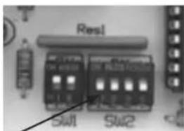
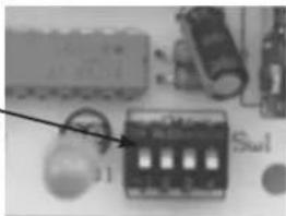
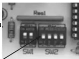
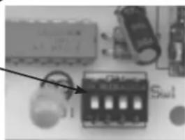
REMOTE ALARM MODULE
The remote alarm module is connected to the SANICUBIC 2 Pro via an HF link. It receives the various types of alarm information from the unit. If other HF appliances interfere with the system, a switching system is fitted for the HF code linking the base board with the remote alarm module.
The code can be changed using the switches located on the 2 boards.
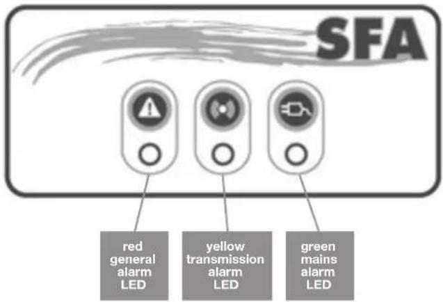
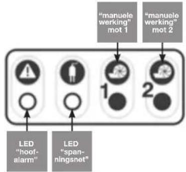
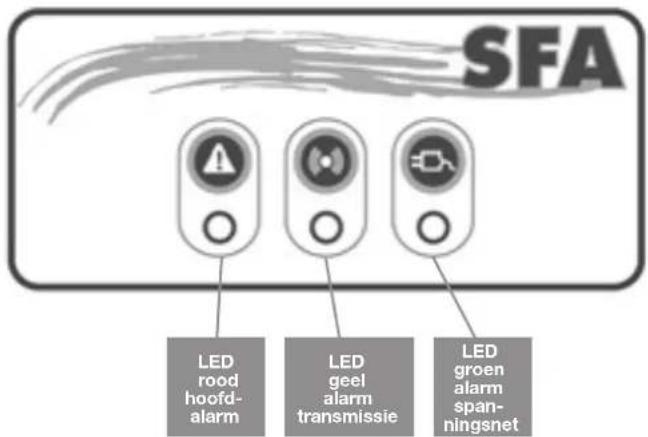
9 ALARM OPERATION
1/ General alarms:
High level alarm:
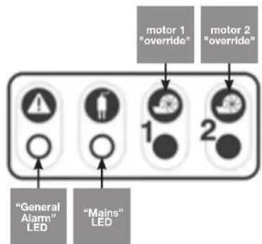
If the water level in the unit is abnormally high: the buzzer is triggered and the red LED comes on; the other motor starts up 3 seconds later (see the illustration showing the control keyboard).
Temporary alarm:
If one of the 2 motors runs for more than 1 minute: the buzzer is triggered and the red alarm LED comes on; the other motor starts up 3 seconds later.
Mains power supply alarm:
In the event of a mains power failure (or if the unit is unplugged): the buzzer is triggered and the red alarm LED comes on; the yellow mains power LED also flashes.
2/ Resetting the general alarms:
If the problem that has triggered one of the alarms referred to above ceases, the buzzer stops, but the red alarm LED stays on to memorize the fact that the system has met with a problem.
One of two keys on the keyboard is used to switch the buzzer off in all cases, but it only switches the red LED off if the problem that triggered the alarm has been dealt with. The alarm lights on the remote control box also stay on until the problem has been dealt with. This avoids the risk of having a system "abandoned" in fault status.
UNIT ALARM
In the event of interference with other HF equipment or other SANICUBIC 2 Pro units installed nearby, unplug the unit and the remote module,
flip one of the 4 switches (or several swithces) on the unit board,
and do the same on the remote unit board.
WARNING: You should have the same code on the unit board and on the remote alarm board.
To install the module on a wall, see illustration:
The alarm module has 5 LEDs and a buzzer.
The LEDs only come on if a fault has been detected.
1/ The red Led "general alarm" LED mirror operation of the corresponding LED on the base board.
2/ The yellow "HF reception" LED mirrors operation of the yellow mains power supply LED on the base board:
- On steadily = transmission OK, base board powered by the mains supply
- Flashing = transmission OK, but mains power supply fault on the base board (which is thus operating on its battery power supply)
Off = no HF reception from the base board = loss of HF signal, or base board battery flat, or base board failure.
3/ The green "mains" LED shows the status of the power supply for the remote alarm module:
- On steadily = module powered by the mains supply
- Flashing = mains supply fault for the module (which is thus operating on its battery power supply)
- Off = module failure or module battery flat
4/ The buzzer stays on continuously during an alarm. It stops if the alarms are no longer present or if you press the button «Reset» General Alarm.
10 CONFORMITY WITH STANDARDS
- SANICUBIC® 2 Pro complies with standard EN 12050-1 (lift station for household waste containing faeces) and with the European directives covering construction products, electrical safety and electromagnetic compatibility
This unit must be installed and used in compliance with European installation standard EN12056 and with local requirements.
COMMISSIONING
1- Once the plumbing and electrical connections have been made, check that the connections are watertight by letting water flow successively through each inlet used. Make sure that the unit is operating correctly by carrying out at least two start cycles with water to test the system.
2 - WARNING! Do not operate the motors in override status (by pressing the pushbuttons on the control box) until the pumps have been filled with water. Operation without water damages the maceration system.
USE
1- The SANICUBIC2 Pro unit is designed to drain off household waste water. Any other use will invalidate the guarantee. Do not dispose of sanitary towels, condoms, hygiene articles, oils, solvents, acids, or any other potentially corrosive or explosive liquids etc., via the unit.
2-WARNING: In the event of a power failure, stop draining any water from the equipment connected to the SANICUBIC® 2 Pro unit.
3- Do not install or use the unit in a zone where there is a risk of explosion.
13 MAINTENANCE
A visual check of the lift station must be made once a month to make sure it is operating correctly, and the installation must be inspected regularly (once a year) by a qualified person. Meanwhile if encounter technical problems, please ask our after-sales service for advice. If the power supply cable of the unit is damaged, it must be replaced by the manufacturer or its after-sales service to avoid all danger.
14 GUARANTEE
The SANICUBIC® 2 Pro unit is guaranteed for two years (parts and labour) provided that it has been installed and used in compliance with the present instructions.
BESCHREIBUNG
LIGACAO DA EVACUACAO
WERKING VAN HET ALARM
1/ Hoofdalarmen:
ALARM VAN HET APPARAAT
DRAADLOZE ALARMUNIT
35 TILSLUTNING AF AFLØBSRØRET
Fjern daekkapperne bag pa pumpen (se 8g1.
3T TILSLUTNING AF VENTILATIONSÄBNINGEN
KPENNEHENE KOPNYCA K NOJY
UTo6bI yCTaHOBka SANICUBIC2 Pro cTOnla npOuHNO HEnoDbNkHO, OHa OChaSeHa DeTaJIaMn KpeJIeHn K IOny.
1- NoCTaBbTe yCTaHOBky Ha HameeHHoe MecTO.
2-HaHnTe 2 OTBepCTnI dNkpePHeHnK nOly.
3-YCTaHOBtE 2 DeTAL KpeJIeHnK NOJy, 3aTEM NocTaBbTe YCTaHOBky.
4-YcTaHOBnTe DeTAnKpePHeHn.3aKpeNTe yCTaHOBky C NOMOuBBO BnHTOB
epeKluOHTe OINn n3 4-x BbIKLIOUaTeIe (nnn HeCKoJIbKO BbIKIoUaTeIe Cpa3y) Ha MmKpOCxEme yCTaHOBKn,
IpeKIOUHTe Te Xe BbIKIOUaTeiN TaXKe Hn Ma MKNPOCXeMe IcTahLcNOHHoCnHaJIIN3aUN.
BHIMAHHE Ha obenx MmKpocxemax OJHKbI 6bITb IpeKeKnOueHbI OINHaKOBBIE BbIKNIOUaTeN, UTO6bl OeCneuTb OINHaKOByIO KOINPOBky.

KpenenHe nHaHn3aun Ha CTeHy.
CnHaJIaI3aIIN OChaIeHa 5 INHIIKaTOpAMN I 13BOHKOM.
INHnkaTOpb3aKnraOTcTOnbKOToTa, KOrDaobHApyKeHa HEnCnpaBHOCTb.
1/ KpacbI CBETOIOID «O6uei TpeBOH» OtpaKaet pa60Ty COOTBeTCTBYUeERO CBEToIOIDA 6a3OBON PnAbl.
2/KeTbI INHnKaTOP «npem B» BOCpOu3BOUIT pa6OTy KEJIToTO INHnKaTopa TOka 6a30Boi KapTbI:
- NOCTOHHO TOpNT = Xopo7aH Npepa7a, 6a3OBaKapTa HAnpJKeHEm n paobTaET OT cTeN;
Mnraetxopoaaanepea,HO6a3oBaKaPa paoTaET OT aKKMyIATopa;
norac = Het BcHana c 6a30BOKapTbI = notepr cnHana BU, nnn aKKyMnTOp 6a30BOKapTbI pa3pHnncr, nnn HeNCpabHOCTb 6a30BOKapTbl.
3/3eHbI INHnKaTOp NITaHnI INCTaHIOHOH CnHaJIIN3aUN:
- NOCTOHHHO TOpNT = NITaHHe OT cETN;
Mnraet=HeNCnpaBHOCTb,CBA3aHHaCPOdaeHNTaHOTcETN(pabotaeAkkymyIANTOP);
-HE ROPNT = NITaHHe He NOdaeTcR.
4/3ByKOBaR CNHahn3aCIN - NOCTOHHbI 3BOHOK. OH nepeCTaET 3BOHNtB B CInyae yCTpaHEHn HEnCnpaBHOCTN, IIN ecNn HaxKaTb Ha KHOKNY «O6HyJIeHne» O6UeI CNHahn3aCIN Ha YCTaHOBKe.
COOTBETCTBNE HOPMAM
YcTaHOBka SANICUBIC 2 Pro OTBeueaet HopMe EN 12050-1 (CTaHnIg OTKaUHbAHnI dIra CTOKOB, CoepKaunx fKeaJIIM), a TaKoe EbpOneIKm DnpeKTHBaM O CTpOnTeJIbHOI npDyKUnn, 3JKeTpNueCKo Be3OpAChOCTn N 3JeKTPomarHHTHOI COBMECTUMOCTn.
YcTaHOBka HcNcNoJIb3OBAHHe DaHHoI CNCTeMbI DOJIHKbI COOTBETCTBOBaTb EBpOeNCKM HopMaM yCTaHOBKn EN12056 n DeIcTByIOUIM MeCTbIM HOpMaM.
11 BBOJ B 3KCNYATAUIO
1- Pocne MOHTaKa TpybOpBoOuB n 3neKtpOnoKnIOueHnnpOBepTe RepMeTNUHOCTb COeINHeHn, NoopePeHcNcyTtB BODy Uepe3 KaXdbI NpOKNIOUeHHb BXoJ. Y6eINTecb, yTO yCTaHOBKa XopoWo paBOtaE, BblONHINNCbItAHn C BOIOJ, KAK MNHMym, Ha 2 cIKJax BKIOUeHn.
1-BHIMAHHE:6e3 BOJbI He BKNIOaJIte HaCOC npINHydntelbHO (HaxKaB Ha KHONK BKNIOUeHNHa KOpnyce).Pa6ota BXOIOCTyIO MOXET BBIECTn n3 CTpor CnCTemy n3MeJIbueHry.
12 NcIIOJIb3OBAHNE
1-SANICUBIO2Pro CO3DAH JINOTKAUHBAHNR CTOKOB TOJbKO 6bITOBOro pOncxOXJeHnR.JIIOBOe dpyrOe npImeHHe npIBODNT KAHNyInPOBaHHIO rapaHTNI. HnB KOem Cnyae He 6pocaiTe B CTOK NOJOTehCa, Ipe3epBaTINbbl, PpeMDteBf TnneHbI, MyCop N He BblNaBtMeacna, paCTBOpNTeN, KNCOTy, UeNoCb N npOue NoTEHcuaNbHO B3PbIBOOnacHbE INI KoppO3NHBie JXIKKOCTN.
2-BHIMAHHE: B cnyuae OTKIIOUeHn 3NEKTPo3HepTINpepekoTe CnIB BOdbI IN3 BCEX NCTOHNKOB,NOdkIOUeHHbIX K SANICUBIC ^ 念 2 Pro.
3- 3anpeuetaetcyaTaHaBnBaTb/ncnoIb3ObaTb CnCTemy BO B3pbIBOONaCHOH 30He.
13 TEXHINCHECKOE OBCJNYKMBAHNE
PpaBnIbHyIO pa6Oy ycTaHOKn CneDyET npOBepaTb 3pntbHo pa3 B MeCHU. YcTaHOBA DOJXHa npoxoHTb peYrAHPbI (exKeOrHbI) KOHTpOB, npBOOMMbIK BAINFCuPOBaHHbIM CneuaNCTOM.Tem He MeHee,ecNI Bbl CTOLKHeTec b C texHnueckmnpoblemamn, obaaauTeCB Cnyk6by nocne npoJaK.B CNyae nobpeKdEHN KabeJIy cTaHOBN er OcJeYET 3aMeHNTb y npOn3BOIDTeN IIN B erO Cnyk6e NocNe npOJaK BO IN66KaHne pNCka KaKnx 6bl TO H 6bl NOBpeKDeHIn.
14 TAPAHTR
CpOK rapaHTmI DeTaneH npa60tbl CnCTeMbI SANICUBIC 2 Pro-2,5rOda pRn yCIOBmYcTAHOBKN INCPOJb3OBAHN B COOTBETCTBN C HAcTOAue NHCPTpyKUeH.
DESCRIEREAPRODUSULUI
This device is not designed for persons (including children) with limited physical, sensory or mental abilities, or those with minimal experience and knowledge, unless they are monitored and are given the necessary instructions for using the device, with the help of a person responsible for their safety. Monitor children and make sure they do not play with the device.

Service information: www.sfa.biz
TEL FAX France N'Azur 10810059002 1 UT par appoi 0344944619 United Kingdom 08457650011 (Call from a land line) 02088421671 Deutschland 08008227820 (06074)30928-90 Espana (93)3818597 (93)4621896 Benelux +34 935446076 +34934621896 Italia 03826181 +39 0382618200 Sverige 08-4041530 08-4041539 Pocsn (495)2582951 (495)2582951 Ireland 1850232425 (LOWCALL) +353 469733093 Polska (+4822) 7320033 (+4822) 7513516 Portugal +351 213507000 +351 219577000 Romania +40 256245092 +40 256245029 USA 1-800-571-8191 1-732-225-6072 Danmark 75644833 75644793 Ceská Republika +420 266712855 +420 266712856 Australia +61 395433891 +61 395436851 中国 0574-88171777 0574-87281907
SERVICE HELPLINES
FRANCE SVERIGE IRELAND SOCIETE FRANCAISE SANIFLO AB 19127 Sollentuna IDA Industrial Estate 8, rue d'Aboukir Tel.08-404 1530 Fax 08-404 1539 Edenderry County Offaly Tel. ^+ 353 46 9733 102 Fax ^+ 353 46 97 33 093 UNITED KINGDOM SFA ITALIA spa POLSKA SANIFLO Ltd., Via del Benessere, 9 27010 Siziano (PV) Tel.03 82 61 81 Fax 03 82 61 8200 USA SFA-SANIFLO INC. 105 Newfield Avenue, Suite A EDISONNJ08837 Tel.1-732-225-6070 Fax1-732-225-6072 DANMARK DANSK VVS IMPORT A/S Gotlandsvej 9 8700 Horsens Telephone 75644833 Fax75644793 AUSTRALIA SANIFLO PTY LTD P.O.Box 5122 Pinewood Victoria 3149 Tel. +61 395433891 Fax +61 395436851 POCCNI SFA POCCNI 101000 Mockba Kolnauhny nep. 9a,kom.103 Teln.(495)2582951 faoKc(495)2582951