Sanipump ZPG 71 - Pump Sanibroyeur - Free user manual and instructions
Find the device manual for free Sanipump ZPG 71 Sanibroyeur in PDF.
| Product type | Submersible grey water pump |
| Brand | Sanibroyeur |
| Model | Sanipump ZPG 71 (variants: .1 S, .1 T, .2 T, .3 T) |
| Power input (P1) | 2.2 kW (ZPG 71.1 S) / 2.1 kW (ZPG 71.1 T) / 3.9 kW (ZPG 71.2 T and 71.3 T) |
| Nominal power (P2) | 1.6 kW (ZPG 71.1 S) / 1.7 kW (ZPG 71.1 T) / 3.2 kW (ZPG 71.2 T and 71.3 T) |
| Supply voltage | 230 V single-phase (ZPG 71.1 S) / 400 V three-phase (other models) |
| Frequency | 50 Hz |
| Nominal current | 10.5 A (ZPG 71.1 S) / 3.7 A (ZPG 71.1 T) / 6.5 A (ZPG 71.2 T and 71.3 T) |
| Rotation speed | 2800 min⁻¹ |
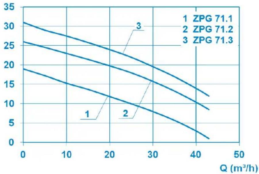
| Max. flow rate | 43 m³/h |
| Max. discharge head | 19 m (ZPG 71.1) / 26 m (ZPG 71.2) / 31 m (ZPG 71.3) |
| Max. fluid temperature | 40 °C |
| Discharge connection | Flange DN50 |
| Weight (cables included) | 38 kg (ZPG 71.1) / 44 kg (ZPG 71.3) |
| Dimensions (H × W × D) | 528 × 130 × 395 mm (approx.) |
| Motor housing material | Grey cast iron GG 20 |
| Impeller material | Grey cast iron GG 20 |
| Mechanical seal | Silicon carbide (SiC) |
| Thermal protection | Bimetallic sensors in the windings (automatic shutoff in case of overheating, restart after cooling) |
| Electrical installation | Connection by a qualified electrician, 30 mA residual current circuit breaker, mandatory grounding (Class I) |
| Maintenance | Check the oil level every 6 to 12 months; other work reserved for the manufacturer or an approved specialist |
| Warranty | 24 months from the date of purchase |
Frequently Asked Questions - Sanipump ZPG 71 Sanibroyeur
User questions about Sanipump ZPG 71 Sanibroyeur
0 question about this device. Answer the ones you know or ask your own.
Ask a new question about this device
Download the instructions for your Pump in PDF format for free! Find your manual Sanipump ZPG 71 - Sanibroyeur and take your electronic device back in hand. On this page are published all the documents necessary for the use of your device. Sanipump ZPG 71 by Sanibroyeur.
USER MANUAL Sanipump ZPG 71 Sanibroyeur
natural_image
Blue industrial pump or motor component with mounting flange and side mount (no visible text or symbols)EN Submersible greywater pump • Operating/installation manual
DE Abwasser-Tauchpumpe • Bedienungs-/Installationsanleitung
FR Pompe submersible pour évacuation des eaux grises • Notice de service/montage
ES Bomba sumergible para aguas residuales • Manual de funcionamento
IT Pompa sommersa per acque reflue • Manuale per l'uso e l'installazione
NL Afvalwater-dompelpomp • Gebruikers-/installatiehandleiding
PT Bomba submersível para águas residuais • Manual de instalação/utilização
English.... 3
Deutsch.... 14
Français 26
Italiano 38
Nederlands.... 50
Español.... 62
Português 74
CONTENTS
1. SAFETY ...... pg.4
1.1 Identifying the warning signs....pg.4
1.2 Personnel qualifications and training ......pg.5
1.3 Dangers from non-observance of the safety instructions.....pg.5
1.4 Safety-awareness at work....pg.5
1.5 Safety instructions for the customer/operator ......pg.5
1.6 Safety instructions for maintenance, inspection and assembly work.pg.5
1.7 Unauthorised re-equipping and spare-part production.....pg.6
1.8 Unauthorised modes of operation....pg.6
2. GENERAL ...... pg.6
2.1 Scope....pg.6
2.2 Queries and orders ......pg.6
2.3 Technical data ......pg.6
2.4 Range of application ......pg.7
2.5 Accessories ......pg.7
3. TRANSPORT AND TEMPORARY STORAGE ......pg.7
4. DESCRIPTION ...... pg.7
4.1 Motors....pg.7
4.2 Pumps....pg.7
4.3 Switching device....pg. 7
5. INSTALLATION ...... pg.8
5.1 Electrical equipment ......pg.8
5.2 Hydraulic system....pg.9
5.3 Level control system....pg.10
6. COMMISSIONING ...... pg.10
7. MAINTENANCE AND REPAIR ...... pg.10
8. MALFUNCTIONS, CAUSES AND TROUBLESHOOTING.... pg.10
9. GUARANTEE....pg.11
10. TECHNICAL MODIFICATIONS ...... pg.11
Appendix A: Characteristic curves ......pg.12
Appendix B: Pump dimensions....pg.12
Appendix C: Sectional drawing and list of spare parts...... pg.13
1. SAFETY
WARNING
This device may be used by children who are at least 8 years old, by people with reduced physical, sensory or mental capacities or those without knowledge or experience, if they are properly supervised and if the instructions relating to using the device completely safely have been given to them and the associated risks have been understood. Children must not play with the device. Cleaning and maintenance undertaken by the user must not be carried out by unsupervised children.
ELECTRICAL CONNECTIONS:
The electrical installation must be done by a qualified electrical engineer.
The device's power supply must be connected to ground (class I) and protected by a high sensitivity differential circuit breaker (30 mA). Devices without plugs must be connected to a main switch on the power supply which disconnects all poles (contact separation distance of at least 3 mm). The connection must be used exclusively to provide the power to the product.
If the power cord is damaged, to prevent possible danger, it must be replaced by the manufacturer, customer service team or a similarly qualified individual.
The operation manual at hand provides basic notes which have to be taken into account during assembly, operation and maintenance works. Therefore, before assembly and commissioning, this operation manual has to be read by the assembler as well as the responsible personnel/operator at all costs. It always has to be available on site of operation of the machine/plant.
The general safety notes listed under the main point safety are not the only notes to be taken into account. Please also observe the specific safety instructions, such as those for private use, listed under other main points.
1.1 Identifying the warning signs
| DANGER | DangerThis term defines a high risk of danger, which can lead to death or serious injury, if not avoided. |
 | Dangerous areaThis symbol characterises hazards that could lead to death or injury. |
 | Dangerous voltageThis symbol characterises dangers associated with the voltage and provides information on voltage protection. |
 | Property damageThis symbol, in combination with the keyword ATTENTION, characterises dangers to the machine and its proper operation. |
It is imperative to observe signs that are attached directly to the machine (for example, rotational direction arrow, sign for fluid connections) and must be kept fully legible.
1.2 Personnel qualifications and training
The personnel responsible for operation, maintenance, inspection and assembly have to have the corresponding qualifications for those types of work. Area of responsibility, competence and the surveillance of the personnel have to be regulated precisely by the operator. If the personnel do not possess the necessary knowledge, they have to be trained and instructed. By order of the operator, the instruction and training, if necessary, can be carried out by the manufacturer/supplier. Furthermore the operator has to make sure that the personnel have completely understood the content of the operation manual.
1.3 Dangers from non-observance of the safety instructions
Non-observance of the safety instructions can result in danger to persons and damage to the environment and the machine. Non-observance of the safety instructions can lead to loss of any claims for damage compensation.
In detail, non-observance can for instance involve the following hazards:
- Failure of important machine/system functions
- Failure of prescribed methods for maintenance and repairs
- Danger to persons through electrical, mechanical and chemical hazards
• Danger to the environment through leakage of harmful substances
1.4 Safety-awareness at work
The safety instructions described in this Operating Manual, the valid national regulations on accident prevention, and possible internal regulations of the customer on work, operation and safety are to be observed.
1.5 Safety instructions for the customer/operator
- Hot or cold machine components which could cause danger have to be secured against contact by the customer.
- Protective devices to prevent touching moving machinery (e.g. coupling) may not be removed from operating machines.
- Leakage (e.g. shaft seals) of dangerous conveyed products (e.g. explosive, poisonous, hot) has to be led off in such a way that there is no endangerment to persons or environment. Legal stipulations are to be maintained.
- Hazards through electric energy are to be eradicated (for details, see national regulations and those of the local power supply companies).
1.6 Safety instructions for maintenance, inspection and assembly work
The customer has to ensure that all maintenance, inspection and assembly work is carried out by authorised and qualified specialist personnel, who have been sufficiently informed through relevant and adequate study of the Operating Manual.
Work on the machine is to be done on principle only when it is shut down. The procedure for shutting down the machine is described in the Operating Manual and is to be precisely adhered to.
Pumps, or pump units that convey hazardous media have to be decontaminated. Immediately after finishing work, all safety and protective devices have to be re-attached and put into effect.
Prior to initial (re-)start-up, you are to take heed of the points listed in the section Initial Operation.
1.7 Unauthorised re-equipping and spare-part production
Re-equipment and modification of the machine are only permitted after consultation with the manufacturer. Original spare parts and accessories authorised by the manufacturer are all part of the safety strategy. Use of other parts can eliminate liability for the consequences that ensue.
1.8 Unauthorised modes of operation
Operational safety of the delivered machine is only guaranteed when it is used appropriately according to Section 2 - General in the Operating Manual. The limit values specified in the data sheet may on no account be exceeded.
2. GENERAL
2.1 Scope
This operation manual is valid for the submersible greywater pumps SANIPUMP® ZPG 71.
If the instructions of the operation manual - especially the safety instructions - are not observed, or in case of unauthorized modifications of the plant or the installation of non-original spare parts, the guarantee expires automatically. The manufacturer assumes no liability for damages resulting from such behaviour!
Manufactured sizes:
| SANIPUMP® ZPG 71.1 S | SANIPUMP® ZPG 71.2 T |
| SANIPUMP® ZPG 71.1 T | SANIPUMP® ZPG 71.3 T |
2.2 Queries and orders
Please send your queries and orders to your specialist dealer.
2.3 Technical data
| SANIPUMP® ZPG 71.1 S ZPG 71.1 T ZPG 71.2 T ZPG 71.3 T | ||||
| P1 [kW] 2.2 2.1 3.9 3.9 | ||||
| Rated power P_2 [kW] 1.6 1.7 1.7 3.2 | ||||
| Voltage U [V] 230 400 400 400 | ||||
| Frequency [Hz] 50 | ||||
| Rated current consumption I [A] 10.5 3.7 3.7 6.5 | ||||
| Drive n [min-1] 2800 | ||||
| Max.discharge flow Q_max [m3/h] 43 43 43 | ||||
| Max. delivery height H_max [m] 19 19 26 31 | ||||
| Max. media temperature t_max [°C] | 40 | |||
| Pressure connection (optional) | Flange DN50 | |||
| Weight with cable [kg] | 38 38 38 | 44 | ||
| Duty ratio ED | S1- continuous operation (flooded), S3- 40% (emerged) | |||
| Minimum fluid level | Bottom line of motor housing | |||
Materials
| Motor housing | Moto | 1.4 | |
| Pump housing | Beari | ||
| Impeller | Floating-ring | ft seal | (silicon carbide) |
| Auxiliary bearing flange | 37-2 | or seals | |
2.4 Range of application
The submersible greywater pumps of the type series SANIPUMP® ZPG 71 are used for the drainage of wastewater in manholes. The use of this pump is not suitable for the disposal of waste water containing faeces (blackwater).
The waste water must not contain any components which affect the materials of the pump or the manhole and its parts.
2.5 Accessories
All pumps of the type series SANIPUMP® ZPG 71 are delivered with 10 m of cable and free cable end. Optional:
- switching devices available as standard or special models with various level control systems;
- a coupling device (stationary operation) for the installation of the pump.
3. TRANSPORT AND TEMPORARY STORAGE
On principle, the pumps SANIPUMP® ZPG 71 should be lifted and/or transported using the eyelets on top or the handlebar designed for that purpose. Under no circumstances is the pump to be lifted on the power supply cable!
For temporary storage and conservation, it suffices if the pumps are stored in a cool, dry, frost-protected and dark place. In case of longer storage periods, please spin the impeller of the pump at least once per month to avoid the jamming of the mechanical seals.
4. DESCRIPTION
4.1 Motors
The pumps SANIPUMP® ZPG 71 are equipped with an AC asynchronous induction motor or a three-phase asynchronous motor. In each of the 3 motor windings one temperature sensors (bi-metal) is integrated which work as temperature regulator respectively temperature limiters (opener). If the motor overheats for any reason, the bimetallic contacts respond to this and the motor is switched off.
4.2 Pumps
The pump housing and the impeller are made of grey cast iron. The pumps are equipped with a flange DN 50.
4.3 Switching device
The pumps with 400 V three-phase motor are delivered without switchgear.
The pumps with 230 V motor are delivered with a switchgear with capacitor and motor protection.
5. INSTALLATION

DANGER


- Disconnect the power supply before carrying out any kind of work on the plant!
- The electrical connections are not to be exposed to humidity!
5.1 Electrical equipment
The AC-powered model of the pump must be operated with the supplied auxiliary switchgear. The pump is connected to an earthed wall socket with an earthed type plug by means of the cable which is connected to the switching device.

DANGER


- The switching device has to be installed outside the flood-endangered area!
- The floater for the protection against dry running has to be installed in such a way, so that a decline of the water level below the bottom line of the motor housing is not possible.
Further electrical installation is not necessary. If required, the motor housing can additionally be earthed by means of the external earthing terminal intended for that.
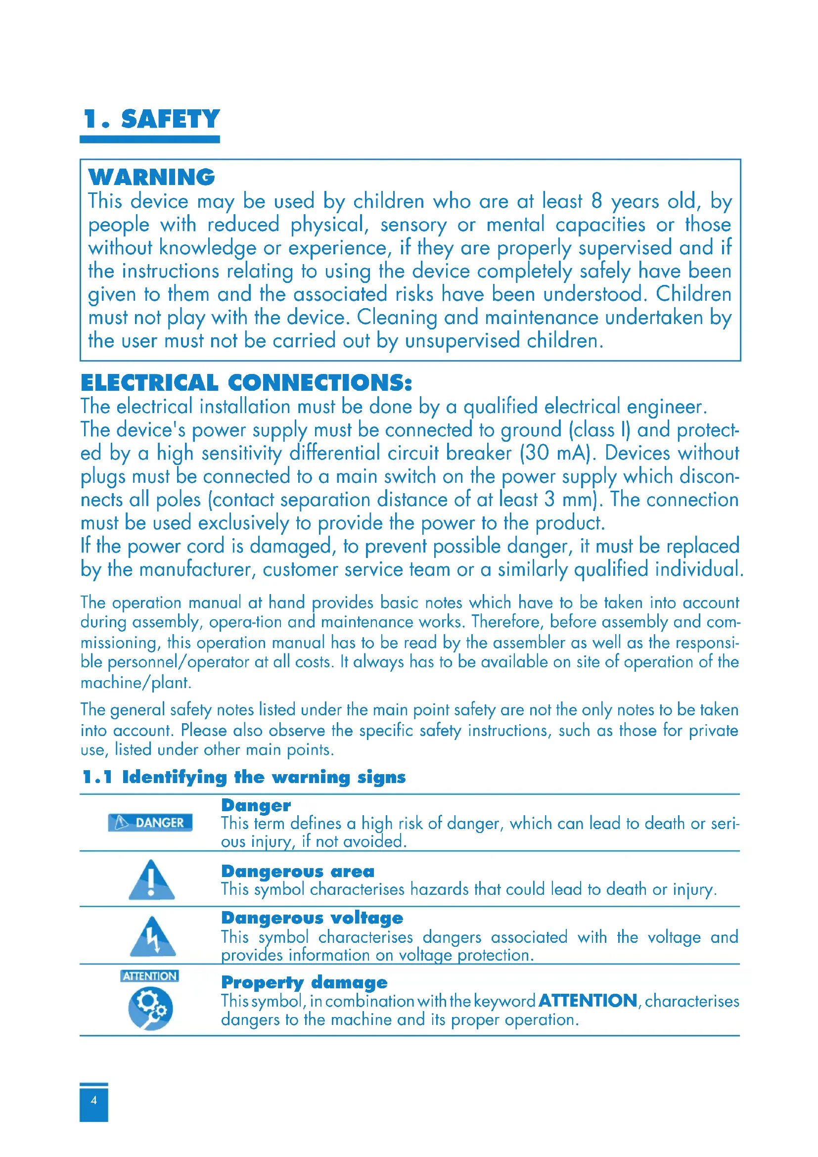
If an additional switching device is connected to the pump SANIPUMP® ZPG 71.1 S, it has to be connected as follows:
text_image
MAINS 1~230 V/50 Hz L1 N Fuse Motor protection Motor relay U1 U2 1 2 Z1 3 Motor capacitor TB1 TB2 4 5 M 1~ 230 V 50 Hz Thermal winding protection Green/Yellow PE conductorThree phase model:
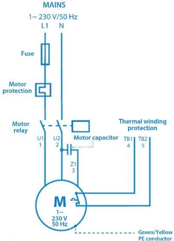
The wires of the seven-wire connection cable of the pumps (three-phase model) are marked as follows:
| Green/Yellow | PE | Ground wire (earthing) |
| 1 | U1 | Three windings, star connection |
| 2 | V1 | |
| 3 | W1 |
| 4 | TB1 | First contact control loop |
| 5 | TB2 | Second contact control loop |

DANGER

- The switching device has to be installed outside the flood-endangered area!
- The floater for the protection against dry running has to be installed in such a way, so that a decline
of the water level below the bottom line of the motor housing is not possible.
Wiring diagrams three phase AC motor:
MAINS
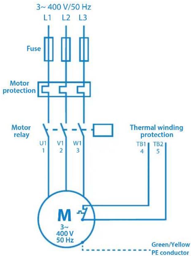
text_image
3~400 V/50 Hz L1 L2 L3 Fuse Motor protection Motor relay U1 V1 W1 1 2 3 M 3~ 400 V 50 Hz TB1 TB2 4 5 Thermal winding protection Green/Yellow PE conductorConnection of the thermal winding cover:
Control loop: T1 and T2 must be connected in a switching device in such a way, that the following function is guaranteed: when the temperature sensors respond, the pump is switched off until the temperature has dropped again. Now the pump is switched on again.
5.2 Hydraulic system

DANGER

The waste water pump must be protected effectively against the suction of air.
Installation with supporting ring:
- Mount supporting ring to intake flange of the pump and install pump. Ensure stability of the pump.
- Connect pressure side by means of flange DN 50.
- If a hose is to be laid on the pressure side, kinks are to be avoided.
- Avoid kinks during the laying of the supply cable. Lay supply cable without tensile loading and without causing chafe marks.
Installation for shaft fitting:
- Position pipe clamp on inner rim of the shaft and loosely fix it with two screws.
- Sound out position of guide pipe frame for coupling pedestal, adjust coupling pedestal on shaft bottom and mount it with the heavy-duty dowels which are included in the delivery.
- Install pressure pipe and valves in a tension-free manner.
- Slip the guide pipe on the coupling pedestal, shorten it to correct length, slip on pipe clamp and tighten it for good.
- Mount coupling element and lowering chain to the pump, lower pump with the chain (insert guide pipe into coupling element) and couple it, hang the chain up on the pipe clamp so that it is ready to hand.
- Lay supply cable. Avoid kinks and lay supply cable without tensile loading and without causing chafe marks.
5.3 Level control system
The pumps SANIPUMP® ZPG 71 have to be controlled by means of a level control in such a way, that a decline of the water level beneath the minimum allowable level (bottom line of motor housing) is avoided at all costs.
The level control can be effected by means of a floating switch, electropneumatically (press switch) or by means of other applicable methods. The switching point of the pump should be set in such a way, that the pump is entirely submersed under water.
6. COMMISSIONING
Check all connections for correct assembly, set gate valve on passage and check level control system for proper operation.
During the initial test run, check pipes for tightness and reseal them, if necessary.
7. MAINTENANCE AND REPAIR

DANGER


Disconnect the power supply before carrying out any kind of work on the plant!
After an operation time of six to twelve months, the oil storage inside the seal carrier always has to be controlled as follows:
- put the pump on its side on a clean surface and position it in such a way that the oil filling screw faces upwards, - take out the screw and check the oil level.
If only a small quantity of oil is lacking, the oil storage can be filled up without any problems. If a considerable quantity of oil is lacking, or if the oil is mingled with water, the customer department has to be informed.
All other maintenance works on the pump and on the electrical equipment should be carried out by the manufacturer or an authorised qualified company in intervals of six to twelve months (or also in shorter intervals, according to case of operation). Please immediately inform the customer department in case of damage to the pump and/or the electrical equipment.
8. MALFUNCTIONS, CAUSES AND TROUBLESHOOTING

DANGER


Disconnect the power supply before carrying out any kind of work on the plant!
| Malfunction Cause Elimination | ||
| 1. Motor is not rotating | - absence of line voltage or improper line voltage | - check voltage supply |
| - incorrect connection - correct the connection | ||
| - defective power cable - replacement (customer service) | ||
| - defective/wrong capacitor - replacement (customer service) | ||
| - impeller/cutting knife blocked - cleaning | ||
| - activated motor protection (overheating, blocking, improper voltage or other malfunction) | - inspection, inform customer service | |
| - control malfunction/defective floating switch | - inspection, inform customer service | |
| - motor defective - replacement (customer service) | ||
| 2. Motor rotates but does not convey | - impeller blocked or worn out - cleaning/replacement | |
| - check valve blocked - cleaning | ||
| - gate valve blocked/closed - cleaning/opening gate valve | ||
| - pressure pipe blocked/hose buckled - cleaning/eliminating kinks | ||
| - intake socket blocked - cleaning | ||
| - incorrect rotating direction - correction | ||
| - water deficiency inside the shaft - switch | off/inform customer service | |
| 3. Motor switches off during start-up | - voltage improper or unsteady - correction/customer service | |
| - thermal protection laid out incorrectly - inspection/customer service | ||
| - current consumption too high | - customer service | |
| 4. Motor does not switch off | - control malfunction | - customer service |
| - wrong/defective floating switch | - replacement/customer service | |
9. WARRANTY
As the manufacturer, we provide a warranty of 24 months on these pumps from date of purchase.
Your sales receipt will act as a proof of warranty. During that warranty period, we gratuitously remedy all deficiencies which are attributed to material or fabrication defects by either repairing the plant, or by replacing the defective parts (to our choice).
Defects which are attributed to misuse or wear are excluded from warranty. We will assume no responsibility for consequential damages that are caused by a breakdown of the plant. In case of a warranty claim, please contact your specialist retailer.
10. TECHNICAL MODIFICATIONS
We reserve all rights for technical modifications in terms of further development.
Appendix A: Characteristic curves
H (m)
line
| Q (m³/h) | ZPG 71.1 | ZPG 71.2 | ZPG 71.3 | | -------- | -------- | -------- | -------- | | 0 | 31 | 26 | 19 | | 10 | 28 | 23 | 15 | | 20 | 24 | 20 | 12 | | 30 | 20 | 16 | 8 | | 40 | 14 | 12 | 4 | | 50 | 8 | 8 | 2 |Appendix B: Pump dimensions
Fixed installation
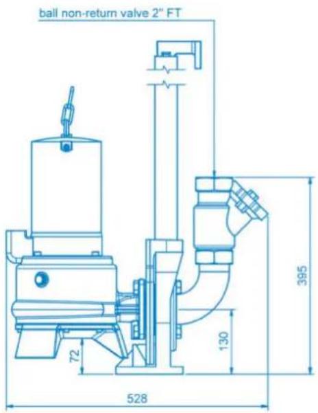
text_image
ball non-return valve 2" FT 72 130 395 528Portable installation
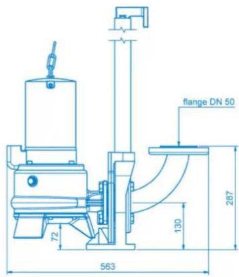
text_image
flange DN 50 72 130 287 563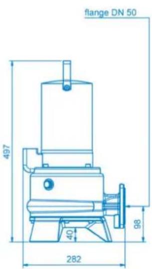
text_image
flange DN 50 497 40 282 98Appendix C: Sectional drawing and list of spare parts
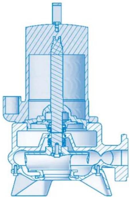
natural_image
Cross-sectional technical drawing of a mechanical pump or valve assembly (no text or labels visible)| Pos. Art. Nr. Designation 1 Designation 2 Quantity | ||||
| 10 17842 Motor | complete SANIPUMP | ®ZPG 71.1 S with bearing flange 1 | ||
| 10 17840 Motor | complete SANIPUMP | ®ZPG 71.1 D with bearing flange 1 | ||
| 10 17370 Motor | complete SANIPUMP | ®ZPG 71.2 T and ZPG 71.3 T 1 | ||
| 11 17854 Parallel key A6x6x10 Form A, DIN6885 1 | ||||
| 20 17356 GLRD | LD1/25-G38 BVPGG 1 | |||
| 30 17377 GLRD | MG1/25-G6 Q1Q1PGG | 1 | ||
| 40 11679 Locking ring A25x1,2 | DIN471 | 1 | ||
| 50 17684 Pump housing ZPG 71 | 1 | |||
| 60 1138 Hexagon socket screw M8x30 A2 | DIN 912 | 4 | ||
| 70 11645 Locking toothed disc S8x13x0,8A2 | 4 | |||
| 80 | 17783 | Impeller ZPG 71.1 | conically machined 21,8° | 1 |
| 80 17782 Impeller ZPG 71.2 | 1 | |||
| 80 17780 Impeller ZPG 71.3 | 1 | |||
| 90 17350 Lid ZPG 71 | 1 | |||
| 100 | 10666 | Hexagon socket screw M6x12 A2 | DIN 912 | 4 |
| 110 | 19501 | Hexagon socket screw M6x18 A2 | DIN 912 | 4 |
| 120 | 11822 O ring 160 x 3,5-NBR70 | 1 | ||
| 160 | 17375 Shim ring 20x30x0,1 1.4301 | 1 | ||
| 170 | 17376 Shim ring 20x30x0,5 1.4301 | 1 | ||
| 180 | 17352 Knife screwing ZPG 71 | 1 | ||
| 190 | 16381 Hexagon socket screw M8x25 A2 | 1 | ||
| 200 | 11672 Sealing ring 8x14x1 Cu | 1 | ||
| 210 | 11663 Ring screw M8 A2 | DIN 580 | 1 | |
| 220 | 10700 | Hexagon socket screw M6x8 A2 | DIN 912 | 2 |
| 230 | 11639 Sealing screw G3/8 | DIN910 | 2 | |
| 240 | 11646 Sealing ring 17x22x1,5 Cu | 2 | ||
| 250 | 11690 | Wisura technical white oil NFW | Wisura white oil | 1 |
| 17468 Switch device ZPG 71.1 S 230V | 1 | |||
INHALT
1. SICHERHEIT \$15
5.2 Hydraulic system
ACHTUNG


natural_image
Cross-sectional technical drawing of a mechanical pump or valve assembly (no text or labels visible)natural_image
Cross-sectional technical drawing of a mechanical pump or valve assembly (no text or labels visible)natural_image
Cross-sectional technical drawing of a mechanical pump or valve assembly (no text or labels visible)natural_image
Cross-sectional technical drawing of a mechanical pump or valve assembly (no text or labels visible)natural_image
Cross-sectional technical drawing of a mechanical pump or valve assembly (no text or labels visible)natural_image
Cross-sectional technical drawing of a mechanical pump or valve assembly (no text or labels visible)| Pos. | Artigo n° | Designação 1 | Designação 2 | Quantidade |
| 10 | 7842 Motor | completo SANIPUMP | ® ZPG 71.1 S | com flange de descarga 1 |
| 10 | 7840 Motor | completo SANIPUMP | ® ZPG 71.1 T | com flange de descarga 1 |
| 10 | 7370 Motor | completo SANIPUMP | ® ZPG 71.2 T e ZPG 71.3 T 1 | |
| 11 | 7854 Chaveta A6x6x10 Forma A, DIN6885 1 | |||
| 20 | 7356 GLRD | LD1/25-G38 BVPGG 1 | ||
| 30 | 7377 GLRD | MG1/25-G6 Q1Q1PGG 1 | ||
| 40 | 1679 Anel | de retenção A25x1,2 DIN471 1 | ||
| 50 | 7684 Caixa da bomba ZPG 71 | 1 | ||
| 60 | 1138 Parafuso sextavado interior M8x30 A2 DIN 912 | 4 | ||
| 70 | 1645 Disco | de catraca S8x13x0,8A2 | 4 | |
| 80 | 17783 | Rotor ZPG 71.1 | maquinada de forma cónica 21,8° | |
| 80 | 7782 Rotor | ZPG 71.2 | 1 | |
| 80 | 7780 Rotor | ZPG 71.3 | 1 | |
| 90 | 7350 Tampa | ZPG 71 | 1 | |
| 100 | 10666 | Parafuso sextavado interior M6x12 A2 | DIN 912 | |
| 110 | 19501 | Parafuso sextavado interior M6x18 A2 | DIN 912 | |
| 120 | 11822 Junta tórica 160 x 3,5-NBR70 | 1 | ||
| 160 | 17375 Disco de ajuste 20x30x0,1 1.4301 | 1 | ||
| 170 | 17376 Disco de ajuste 20x30x0,5 1.4301 | 1 | ||
| 180 | 17352 União roscada da lâmina ZPG 71 | 1 | ||
| 190 | 16381 Parafuso sextavado interior M8x25 A2 | 1 | ||
| 200 | 11672 Anel de vedação 8x14x1 Cu | 1 | ||
| 210 | 11663 | Parafuso olhal M8 A2 | DIN 580 | |
| 220 | 10700 | Parafuso sextavado interior M6x8 A2 | DIN 912 | |
| 230 | 11639 | Parafuso de aperto G3/8 | DIN910 2 | |
| 240 | 11646 Anel de vedação 17x22x1,5 Cu | 2 | ||
| 250 | 11690 | Wisura Óleo branco técnico NFW | Óleo branco Wisura | |
| 17468 Caixa de controlo ZPG 71.1 S 230V | 1 | |||
www.sfa.biz
SERVICE HELPLINES
France
Tel. 01 44 82 25 55
Fax. 03 44 94 46 19
United Kingdom
Tel. 08457 650011
(Call from a land line)
Fax. 020 8842 1671
Ireland
Tel. 1850 23 24 25
(LOW CALL)
Fax. + 353 46 97 33 093
Australia
Tel. +1300 554 779
Fax. +61.2.9882.6950
Deutschland
Tel. 0800 82 27 82 0
Fax. (060 74) 30928-90
Italia
Tel. 0382 6181
Fax. +39 0382 618200
España
Tel. +34 93 544 60 76
Fax. +34 93 462 18 96
Portugal
Tel. +35 21 911 27 85
sfa@sfa.pt