
59G873 - Saw Graphite - Free user manual and instructions
Find the device manual for free 59G873 Graphite in PDF.
| Product Type | Metal Cutting Machine |
| Brand | Graphite |
| Model | 59G873 |
| Supply Voltage | 230 V ~ |
| Frequency | 50 Hz |
| Rated Power | 2600 W |
| No-Load Speed | 3800 min⁻¹ |
| Outer Disc Diameter | 355 mm |
| Inner Disc Diameter | 25.4 mm |
| Vice Angle Adjustment | 0° to 45° |
| Cutting Capacity at 90° (square profile) | 110 x 110 mm |
| Cutting Capacity at 90° (rectangular profile) | 170 x 90 mm |
| Cutting Capacity at 90° (round profile) | 110 mm |
| Weight | 17 kg |
| Protection Class | II |
| Production Year | 2020 |
| Sound Pressure Level (LpA) | 92.5 dB(A) |
| Sound Power Level (LwA) | 105.5 dB(A) |
| Vibration Acceleration Value (ah) | < 2.5 m/s² |
| Safety | Safety switch, movable disc guard, spindle lock |
| Maintenance | Regular cleaning, replacement of carbon brushes and cutting disc |
| Included Accessories | Hex key, locking pin, crank handle |
| Usage | Indoor, for metal cutting (DIY and light workshop) |
Frequently Asked Questions - 59G873 Graphite
User questions about 59G873 Graphite
0 question about this device. Answer the ones you know or ask your own.
Ask a new question about this device
Download the instructions for your Saw in PDF format for free! Find your manual 59G873 - Graphite and take your electronic device back in hand. On this page are published all the documents necessary for the use of your device. 59G873 by Graphite.
USER MANUAL 59G873 Graphite
59G873

PL INSTRUKCJA OBSŁUGI....4
EN INSTRUCTION MANUAL....8
SR UPUTSTVO ZA UPOTREBU....57
FR MANUEL D'INSTRUCTION....77

UWAGA: PRZED PRZYSTĄPIENIEM DO UŻYTKOWANIA ELEKTRONARZĘDZIA NALEŻY UWAŻNIE PRZECZYTAĆ NINIEJSZĄ INSTRUKCJĘ I ZACHOWAĆ JĄ DO DALSZEGO WYKORZYSTANIA.
SZCZEGÓŁOWE PRZEPISY BEZPIECZEŃSTWA

NOTE: BEFORE THE POWER TOOL IS USED FOR THE FIRST TIME, READ THIS INSTRUCTION MANUAL AND KEEP IT FOR FUTURE REFERENCE.
DETAILED SAFETY REGULATIONS
Safety instructions for cut-off machines 1. Cut-off machine safety warnings
a) Position yourself and bystanders away from the plane of the rotating wheel. The guard helps to protect the operator from broken wheel fragments and accidental contact with wheel.
b) Use only bonded reinforced cut-off wheels for your power tool. Just because an accessory can be attached to your power tool, it does not assure safe operation.
c) The rated speed of the accessory must be at least equal to the maximum speed marked on the power tool. Accessories running faster than their rated speed can break and fly apart.
d) Wheels must be used only recommended applications. For example: do not grind with the side of a cut-off wheel. Abrasive cut-off wheels are intended for peripheral grinding, side forces applied to these wheels may cause them to shatter.
e) Always use undamaged wheel flanges that are of correct diameter for your selected wheel. Proper wheel flanges support the wheel thus reducing possibility of wheel breakage.
f) The outside diameter and the thickness of your accessory must be within the capacity rating of your power tool. Incorrectly sized accessories cannot be adequately guarded or controlled.
g) The arbour size of wheels and flanges must properly fit the spindle of the power tool. Wheels and flanges with arbour holes that do not much the mounting hardware of the power tool will run out of balance, vibrate excessively and may cause loss of control.
h) Do not use damaged wheels. Before each use, inspect the wheels for chips and cracks. If the power tool or wheel is dropped, inspect for damage or install an undamaged wheel. After inspecting and installing the wheel, position yourself and bystanders away from the plane of the rotating wheel and run the power tool at maximum no load speed for one minute. Damaged wheels will normally break apart during this test time.
i) Wear personal protective equipment. Depending on application, use face shield, safety goggles or safety glasses. As appropriate, wear dust mask, hearing protectors, gloves and shop apron capable of stopping small abrasive or workpiece fragments. The eye protection must be capable of stopping flying debris generated by various operations. The dust mask or respirator must be capable of filtrating particles generated by your operation. Prolonged exposure to high intensity noise may cause hearing loos.
j) Keep bystanders a safe distance away from work area. Anyone entering the work must wear personal protective equipment. Fragments of workpiece or of a broken wheel may fly away and cause injury beyond immediate area of operation.
k) Position the cord clear of the spinning accessory. If you lose control, the cord may be cut or snagged and your hand or arm may be pulled into the spinning wheel.
I) Regularly clean the power tool's air vents. The motor's fan can draw the dust inside the housing and excessive accumulation of powdered metal may cause electrical hazards.
m) Do not operate the power tool near flammable materials. Do not operate the power tool while placed on a combustible surface such as wood. Sparks could ignite these materials.
n) Do not use accessories that require liquid coolants. Using water or other liquid coolants may result in electrocution or shock.
2. Kickback and related warnings
Kickback is a sudden reaction to a pinched or snagged rotating wheel. Pinching or snagging causes rapid stalling of the rotation wheel which in turn causes the uncontrolled cutting unit to be forced upwards toward the operator;
For example, if an abrasive wheel is snagged or pinched by the workpiece, the edge of the wheel that in entering into the pinch point can did into the surface of the material causing the wheel to climb out or kick out. Abrasive wheels may also break under these conditions.
Kickback is the result of power tool misuse and/or incorrect operating procedures or conditions and can be avoided by taking proper precautions as given below.
a) Maintain a firm grip on the power tool and position your body and arm to allow you to resist kickback forces. The operator can control upward kickback forces, if proper precautions are taken.
b) Do not position your body in line with the rotating wheel. If kickback occurs, it will propel the cutting unit upwards toward the operator.
c) Do not attach a saw chain, woodcarving blade, segmented diamond wheel with a peripheral gap greater than 10 mm or toothed saw blade. Such blades create frequent kickback and loss of control.
d) Do not "jam" the wheel or apply excessive pressure. Do not attempt to make an excessive depth of cut. Overstressing the wheel increases the loading and susceptibility to twisting or binding of the wheel in the cut and the possibility of kickback or wheel breakage.
e) When the wheel is binding or when interrupting a cut for any reason, switch off the power tool and hold the cutting until motionless until the wheel comes to a complete stop. Never attempt to remove the wheel from the cut while the wheel is in motion otherwise kickback may occur. Investigate and take corrective action to eliminate the cause of wheel binding.
f) Do not restart the cutting operation in the workpiece. Let the wheel reach full speed and carefully re-enter the cut. The wheel may bind, walk up or kickback if the power tool is restarted in the workpiece.
g) Support any oversized workpiece to minimize the risk of wheel pinching and kickback. Large workpieces tend to sag under their own weight. Support must be placed under the workpiece near the line of cut and near the edge of the workpiece on both sides of the wheel.
WARNING! The device is used for indoor work.
Despite the use of a safe structure by design, the use of protective measures and additional protective measures, there is always a residual risk of injury during work.
EXPLANATION OF THE PICTOGRAMS USED
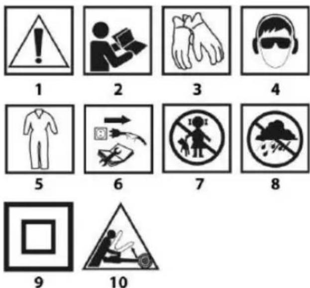
- Attention! Take special precautions
- WARNING Read the instruction manual
- Wear protective gloves
- Use personal protective equipment (safety goggles, ear protectors, dust mask)
- Use protective clothing
-
Unplug the power cord before servicing or repair
-
Keep children away from tools
- Protect the device against moisture
- Second protection class
- Risk of recoil.
DETAILED SAFETY REGULATIONS
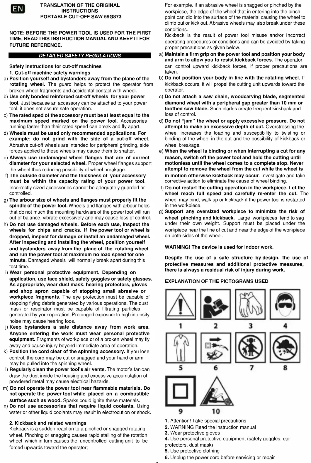
CONSTRUCTION AND USE
Portable cut off saw is designed for cutting pieces of metal that match with the tool size. Use the portable cut off saw only with cutting discs designed for this tool.
Do not use cutting discs made of high speed steel, solid carbide, diamond etc.
The tool is designed for light duty works in service workshops and for individual, amateur activities (tinkering). Attempts to use the portable cut off saw for purposes other than specified will be considered an improper use.
Use the tool according to its purpose only.
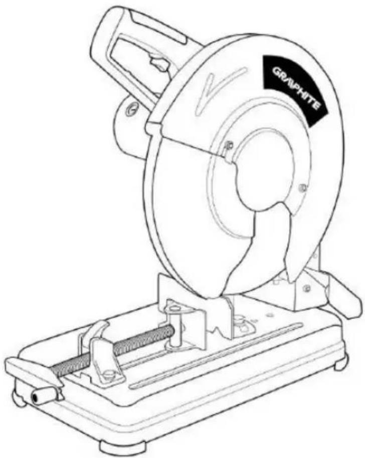
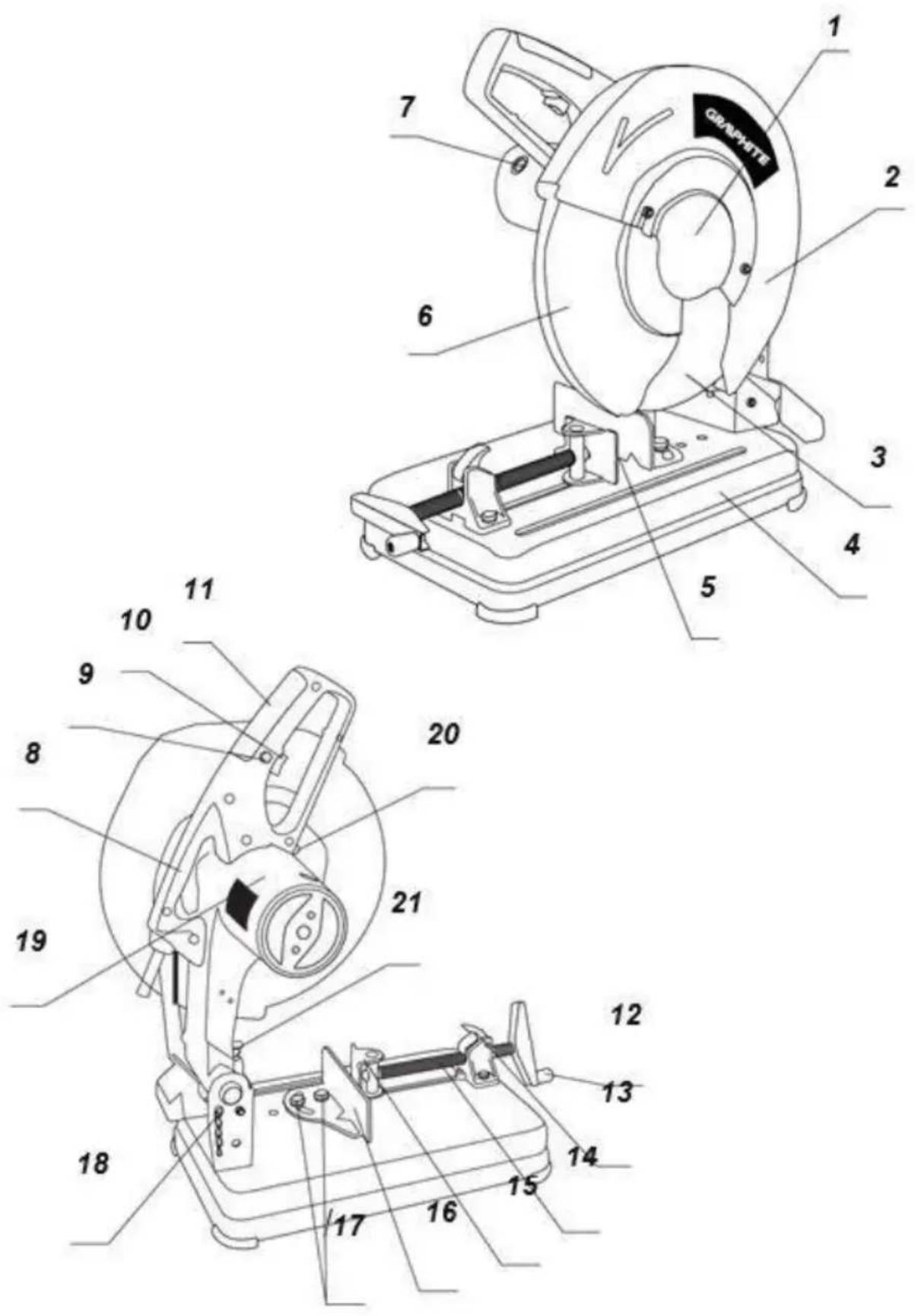
DESCRIPTION OF DRAWING PAGES
Below enumeration refers to the device elements depicted on the drawing pages of this manual.
- Side shield for cutting disc
- Stationary shield
- Cutting disc
- Base
- Vice
- Movable shield for cutting disc
- Carbon brush cover
- Transport handle
- Safety switch
- Switch
- Handle
- Crank
- Split nut of vice screw
- Vice screw
- Sliding jaw
- Fixed jaw
- Fixing screws for fixed jaw
- Head locking pin
- Head
- Spindle lock
- Adjustment screw
* Differences may appear between the product and drawing.
EQUIPMENT AND ACCESSORIES
- Two sided ring spanner - 1 pce
- Locking pin - 1 pce
- Crank - 1 pce
Remove power cord plug from mains socket before working at the device.
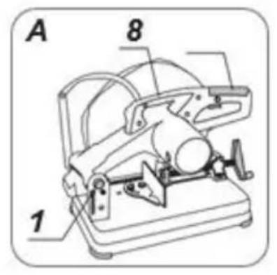
TRANSPORT PROTECTION / MOVING THE PORTABLE CUT OFF SAW
Secure the head in the lowest position for transportation.
- Use the handle (11) to press the head (19) in the lowest position possible and secure with the head locking pin (18) (fig. A).
- When lifting the portable cut off saw hold the transport handle (8). Do not carry the portable cut off saw when holding the handle (11).
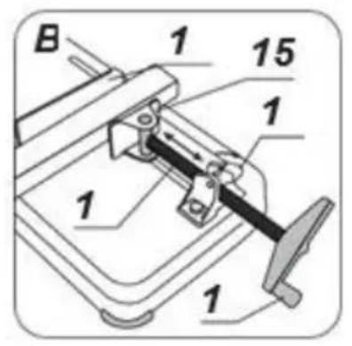
VICE
Each piece of material must be well fixed in the vice before cutting.
The split nut of vice screw (13) allows fast advance of the vice screw (14) to move the sliding jaw (15) towards material without turning the crank (12).
- Lift upper part of the split nut of vice screw (13).
- Slide the vice screw (14) to appropriate distance, so it is possible to fix material between surfaces of jaws
• (15) and (16). -
Place material between jaws, slide the vice screw (14) back so the sliding jaw (15) surface contacts the material (fig. B).
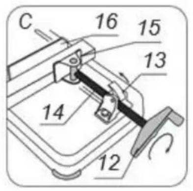
-
Close upper part of the split nut of vice screw (13) to join thread with the vice screw (14). Turn the crank
• (12) to tighten the material between jaws (fig. C).
Ensure the portable cut off saw is disconnected from power supply network before starting any adjustment task. To ensure safe, precise and efficient cut off saw operation, proceed with all adjustment procedures as a whole.
After finishing all the setting and adjustment procedures ensure that all adjustment keys are collected. Check that all joining elements are properly fitted.
When making adjustments ensure that all external parts work properly and conform with all conditions necessary for proper operation. Any worn out or damaged part must be replaced by qualified personnel before starting to use the portable cut off saw.
INSTRUCTIONS FOR CUTTING
- It is recommended to make a try cut after each adjustment to make sure the new settings are correct and to check dimensions.
- After switching the portable cut off saw on, wait until cutting disc reaches its top maximum speed while running idle, only then you can proceed with cutting.
- Secure long objects from falling after cutting (e.g. with a roller support).
- Be very careful when starting a cut!
- Wait until cutting disc comes to a complete stop, only then you can remove cut off pieces.
SWITCHING ON / SWITCHING OFF
The mains voltage must match the voltage on the label of the cut off saw.
Switch on the saw only when the material that is to be cut is away from the cutting disc.
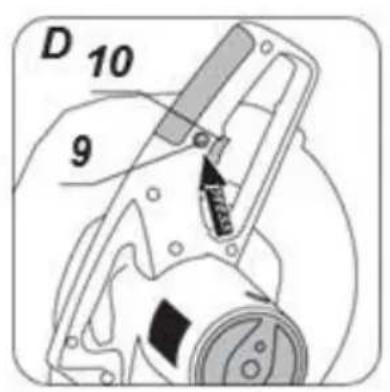
The portable cut off saw features safety switch (9) that protects against accidental or unintentional start up.
Switching on
- Press the safety switch button (9).
- Press and hold the switch button (10) (fig. D).
Switching off
- Release pressure on the switch button (10).
CHECKING AND ADJUSTMENT OF CUTTING DEPTH
It is necessary to check maximal cutting depth to ensure the cutting disc will cut the material completely. Set up the portable cut off saw, so the lowest point of the cutting disc penetrates at least 5 mm below upper surface of the base. Adjustments are necessary to compensate for wear of the cutting disc.
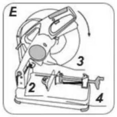
Use the adjustment screw (21) to adjust head (19) travel downwards.
- Lower the head (19) and hold down pressed against head of the adjustment screw (21).
- Loosen the lock nut and screw the adjustment screw (21) in or out if necessary, so the cutting disc (3) position is correct (5 mm below upper surface of the base (4)) (fig. E).
- Tighten the lock nut to secure the setting.
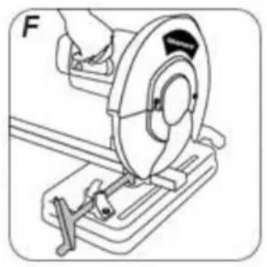
CUTTING
The return spring of the saw arm automatically moves the head to upper position. Therefore, do not release pressure on the handle after cutting, instead hold it slightly and allow the head to return to the topmost position.
• Fix the material tightly in the vice (5).
- Switch on the portable cut off saw and wait until motor reaches its full rotational speed.
- Use the handle (11) to press the head (19) downwards until the cutting disc (3) slightly contacts the material to cut.
- Apply steady pressure on the head and make a cut (fig. F).
Do not reduce pressure at the end of a cut, otherwise the cut material may get overheated and there may be uneven edges.
Do not allow vibrations or cutting disc bouncing on material, it would adversely affect cut quality and may cause crack in the cutting disc.
CUTTING LARGE PIECES
When fixing a wide piece of material, you can move the fixed jaw away to increase distance between vice jaws.
- Set the head (19) in upper position.
- Unscrew the fixing screws for fixed jaw (17).
- Reinstall the fixed jaw (16) to holes located closer to the head arm and attach by tightening the fixing screws for fixed jaw (17). Number of cuts possible to do with cutting disc and quality may vary, depending on the cutting speed. Fast cutting may cause early wear of cutting disc, but protects the material against overheating and ensures smooth cut surface.
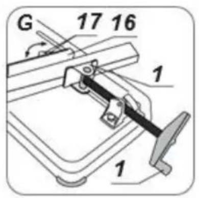
SETTING THE VICE FOR MITRE CUTTING
The fixed jaw (16) also has a function of mitre gauge and allows to cut material at any angle after adjustment within range from right angle position to 450 left or right.
- Set the head (19) in upper position.
- Loosen the fixing screws for fixed jaw (17).
- Turn the fixed jaw (16) to required cutting angle accordingly to the angle scale and secure position by tightening the fixing screws for fixed jaw (17) loosened earlier (fig. G).
• Fix material in the vice and make a cut.
Even though the angle scale in fixed jaw is accurate enough for most of performed tasks, it is recommended to double-check the cutting angle with protractor or other device for angle measurements.
When fixing material in the vice, the sliding jaw (15) aligns itself in parallel to fixed material, ensuring it is well secured.
Unplug the power cord from mains socket before commencing any activities related to installation, adjustment, repair or maintenance.
- When the work is finished, remove thoroughly all pieces of material and dust from the base and area around cutting disc and its shield.
- Clean the portable cut off saw with brush or stream of compressed air.
- Never use water or other chemical liquids for cleaning the portable cut off saw.
- Clean ventilation holes regularly to prevent motor overheating.
- Store the portable cut off saw in a dry place, beyond reach of children.
- Entrust replacement of power cord and other repairs only to authorized service workshop.
Regularly check that all bolts and fixing screws are tightened. They may get loosened after some time of operation.
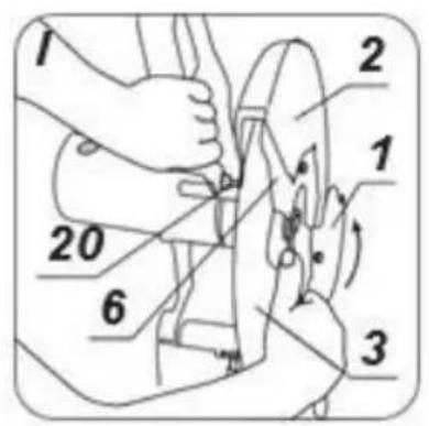
CUTTING DISC REPLACEMENT
- Set the head (19) in upper position.
- Place the movable shield for cutting disc (6) in its upper position.
- Loosen the nuts and take the side shield of the cutting disc (1) to the back (fig. H).
- Push the spindle lock (20) in so the pin goes through the hole in the movable shield for cutting disc (6) and turn the cutting disc (3) with your hand until it locks.
- Use ring spanner (included) to unscrew the screw fixing cutting disc (3) by turning it counter-clockwise (fig. I).
- Remove the screw fixing cutting disc, washer and outer collar, and remove the cutting disc (3) carefully.
- Clean the collars thoroughly before installing a new cutting disc.
- Place new cutting disc and tighten its fixing screw, while holding the spindle lock (20) pressed in.
- Release the spindle lock (20).
• Install the side shield for cutting disc (1) and tighten nuts.
- Use the handle (11) to move the head (19) downwards, so the movable shield for cutting disc (6) is unlocked.
- Make sure the movable shield for cutting disc (6) operates correctly.
Use only recommended and reinforced cutting discs. Tighten screw that fixes cutting disc, so the wheel is well clamped and cannot rotate. When the cutting disc fixing screw is overtightened, the wheel may get damaged.
REPLACEMENT OF CARBON BRUSHES
Replace immediately worn out (shorter than 5 mm), burnt or cracked motor carbon brushes. Always replace both brushes at a time.
- Unscrew and remove carbon brush covers (7).
- Remove worn out carbon brushes.
- Remove any carbon dust with compressed air.
- Insert new carbon brushes. Brushes should easily move into brush-holders.
• Fix carbon brush covers (7).
After the carbon brushes are replaced, start the portable cut off saw with no load for approximately 2-3 minutes until the carbon brushes fit to the motor commutator. It is recommended to entrust replacement of carbon brushes only to a qualified person. Only original parts should be used.
All faults should be repaired by service workshop authorized by the manufacturer.
TECHNICAL PARAMETERS
| Metal cutting machine 59G873 | |
| Parameter | Value |
| Supply voltage | 230V ~ |
| Power frequency | 50 Hz |
| Rated power | 26 00W |
| Blade rotational speed (without load) | 3800 min -1 |
| Vise angle adjustment | 0 ÷ 45 ° |
| Outer diameter of the disc | 355 mm |
| Inner diameter of the disc | 25 , 4 mm |
| Behind the cutting line at 90 ° (angle) | 120x120mm |
| Cutting range at 90 ° (square profile) | 110x110mm |
| Cutting range at 90 ° (rectangular profile) | 170x90mm |
| Cutting range at 90 ° (round profile) | 110mm |
| Protection class | II |
| Mass | 17 kg |
| Year of production | 2020 |
| 5 9G873 means both machine type and machine description | |
NOISE AND VIBRATION DATA
| Sound pressure level | LPA = 92.5 dB (A) K = 3 dB (A) |
| Sound power level | LWA = 105.5 dB (A) K = 3 dB (A) |
| Acceleration value | and h < 2, 5 m/s2 |
Information on noise and vibration
The level of noise emitted by the device is described by: the level of emitted sound pressure Lp A and the level of acoustic power Lw A (where K is the measurement uncertainty). Vibration emitted by the device is described by the value of vibration acceleration a h (where K is the measurement uncertainty).
The level of emitted sound pressure Lp A, the sound power level Lw A and the value of vibration acceleration a h given in this manual were measured in accordance with EN 62841-1. The given vibration level a h can be used to compare devices and to initially assess vibration exposure.
The given vibration level is representative only for the basic applications of the device. If the device is used for other applications or with other working tools, the vibration level may change. Insufficient or too rare maintenance of the device will affect the higher level of vibration. The above-mentioned causes may cause increased vibration exposure during the entire working period.
To accurately estimate vibration exposure, consider the periods when the device is turned off or when it is turned on but is not used. After careful estimation of all factors, the total vibration exposure may be much lower.
In order to protect the user against the effects of vibrations, additional safety measures should be introduced, such as: cyclical maintenance of the device and working tools, protection of the right hand temperature and proper organization of work.
ENVIRONMENTAL PROTECTION
Electrical equipment must not be disposed off with household waste and, instead, should be utilized at appropriate facilities. Information on utilization can be provided by the product vendor or the local authorities. Waste electrical and electronic equipment contains substances that are not neutral to the natural environment. Equipment that is not recycled constitutes a potential hazard to the environment and to human health.
* Right to introduce changes is reserved.
"Grupa Topex Spółka z ograniczoną odpowiedzialnością" Spółka komandytowa with seat in Warsaw at ul. Pograniczna 2/4 (hereinafter Grupa Topex) informs, that all copyrights to this instruction (hereinafter Instruction), including, but not limited to, text, photographies, schemes, drawings and layout of the instruction, belong to Grupa Topex exclusively and are protected by laws accordingly to Copyright and Related Rights Act of 4 February 2004 (ustawa o prawie autorskim i prawach pokrewnych, Dz. U. 2006 No 90 item 631 with later amendments). Copying, processing, publishing, modifications for commercial purposes of the entire Instruction or its parts without written permission of Grupa Topex are strictly forbidden and may cause civil and legal liability.

DETALJNI PROPISI SIGURNOSTI
REEMPLACEMENT DES BROSSES EN CARBONE
EC Declaration of Conformity
Manufacturer: Grupa Topex Sp. z o.o. Sp.k., Pograniczna 2/4 02-285 Warszawa
Product: Metal cutting machine
Model: 59G873
Trade name: GRAPHITE
Serial number: 00001 ÷ 99999
This declaration of conformity is issued under the sole responsibility of the manufacturer.
- The product described above complies with the following documents:
Machinery Directive 2006/42/EC
Electromagnetic Compatibility Directive 2014/30/EU
RoHS Directive 2011/65/EU as amended by Directive 2015/863/EU
And meets the requirements of the standards:
EN 62841-1:2015+A11:2022; EN 62841-3-
10:2015+A11:2017+A1:2022+A12:2022;
EN IEC 55014-1:2021; EN IEC 55014-2:2021; EN IEC 61000-3-
2:2019+A1:2021; EN IEC 61000-3-11:2019;
-
EN IEC 63000:2018
-
This declaration relates only to the machinery as placed on the market and does not include components
-
added by the end user or carried out by him/her subsequently.
-
Name and address of the EU resident person authorised to prepare the technical dossier:
Signed on behalf of:
Grupa Topex Sp. z o.o. Sp.k.
TOPEX GROUP Quality Officer
Warsaw, 2023-07-31
DE
Directive Machines 2006/42/CE


- SZCZEGÓŁOWE PRZEPISY BEZPIECZEŃSTWA
- DETAILED SAFETY REGULATIONS
- KICKBACK AND RELATED WARNINGS
- CONSTRUCTION AND USE
- DESCRIPTION OF DRAWING PAGES
- EQUIPMENT AND ACCESSORIES
- TRANSPORT PROTECTION / MOVING THE PORTABLE CUT OFF SAW
- VICE
- EACH PIECE OF MATERIAL MUST BE WELL FIXED IN THE VICE BEFORE CUTTING
- INSTRUCTIONS FOR CUTTING
- SWITCHING ON / SWITCHING OFF
- SWITCHING ON
- SWITCHING OFF
- CHECKING AND ADJUSTMENT OF CUTTING DEPTH
- CUTTING
- CUTTING LARGE PIECES
- SETTING THE VICE FOR MITRE CUTTING
- CUTTING DISC REPLACEMENT
- REPLACEMENT OF CARBON BRUSHES
- INFORMATION ON NOISE AND VIBRATION
- ENVIRONMENTAL PROTECTION
- DETALJNI PROPISI SIGURNOSTI
- REEMPLACEMENT DES BROSSES EN CARBONE
- EC DECLARATION OF CONFORMITY
- DE
Brand : Graphite
Model : 59G873
Category : Saw