WSFP 8 - Welding machine Weller - Free user manual and instructions
Find the device manual for free WSFP 8 Weller in PDF.
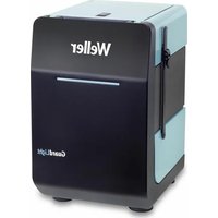
| Product type | Soldering station with automatic wire feed |
| Brand | Weller |
| Model | WSFP 8 |
| Power supply | 230 V / 50 Hz |
| Power | 90 W |
| Fuse | T800 mA |
| Temperature range | 50 °C – 450 °C (continuous adjustment) |
| Temperature accuracy | ± 9 °C |
| Output voltage | 24 V AC (channel 1), 24 V DC (channel 2) |
| Display | Digital, switchable between temperature and feed |
| Feed modes | SFA (sequential) and SFC (continuous) |
| Solder quantity (SFA) | 1 – 300 (steps of 10 ms) |
| Feed speed (SFC) | 10 % – 100 % |
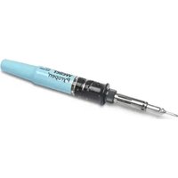
| Compatible wire diameter | 0.5 – 0.8 mm (WSF P5) or 0.8 – 1.5 mm (WSF P8) |
| Spool capacity | Up to 1 kg |
| Safety functions | Automatic reduction to 150 °C (Setback), automatic shut-off (Auto Off), potential compensation |
| Potential-free contact | Yes, 24 V / 20 mA max |
| External options | WCB1/WCB2 (controller, PC interface), foot switch |
| Maintenance | Clean the drive roller with a brass brush; tin the tip before storage |
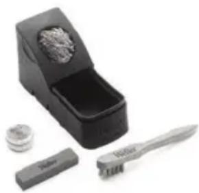
| Included accessories | Soldering iron WSF P, stand, small tool, power cord, manual |
Frequently Asked Questions - WSFP 8 Weller
User questions about WSFP 8 Weller
0 question about this device. Answer the ones you know or ask your own.
Ask a new question about this device
Download the instructions for your Welding machine in PDF format for free! Find your manual WSFP 8 - Weller and take your electronic device back in hand. On this page are published all the documents necessary for the use of your device. WSFP 8 by Weller.
USER MANUAL WSFP 8 Weller
natural_image
Product photo of a Weller VSPZ soldering machine with a soldering iron and its base (no visible text or symbols)GB Translation of the original instructions
natural_image
Circular icon with a lowercase 'i' in the center, commonly used to denote information (no additional text or symbols)
www.weller-tools.com
MANUAL

| DE Deutsch | Achtung! | Beschreibung | Bedienungsprinzip | Inbetriebnahme | Potentialausgleich | Arbeitshinweise Löten | Zubehör | Lieferumfang | 9 |
| FR Français | Attention! | Description | Principe d'utilisation | Mise en service de l'appareil | Compensation de poten-tiel | Consignes de travail Soudage | Accessoires | Fourniture | 13 |
| NL Nederlands | Attentie! | Beschrijving | Bedieningsprincipe | Toestel in gebruik nemen | Potientiaalvereffening | Werk-wijze Solderen | Toebehoren | Meegeleverd van de levering | 17 |
| IT Italiano | Attenzione! | Descrizione | Filosofia di comando | Messa in funzione dell'apparecchio | Compensazione di potenziale | Istruzioni di lavoro Saldare | Accessori | Dotazione | 21 |
| GB English | Caution! | Description | Operating principle | Starting up the device | Equipotential bonding | Operating guidelines Soldering | Accessories | Included in delivery | 25 |
| SV Svenska | Varning! | Beskrivning | Användningsprincip | Ta lödstationen i drift | Potentialutjämning | Arbetsanvis- ningar Lödning | Tillbehör | Leveransomfattning | 29 |
| ES Español | Atención! | Descripción | Manejo | Puesta en servicio del aparato | Equipotencial | Instrucciones Soltar | Accesorios | Piezas suministradas | 33 |
| DK Dansk | Bemærk! | Beskrivelse | Betjeningsprincip | Ibrugtagning af apparatet | Spændingsudligning | Arbejd-sanvisninger Lodning | Tilbehør | Leveringsomfang | 37 |
| PT Portugues | Atenção! | Descrição | Princípio de utilização | Colocação do aparelho em serviço | Equilíbrio do poten-cial | Indicações de trabalho Soldar | Acessórios | Fornecimento | 41 |
| FI Suomi | Huomio! | Kuvaus | Käyttöperiaate | Laitteen käyttöönotto | Potentiaalin tasaus | Toimintaohjeet Juot-taminen | Tarvikkeet | Toimitussisältö | 45 |
| GR Ελληνικα | Προσοχή! | Περιγραφή | Αρχή χειρισμού | Θέση της συσκευής σε λειτουργία | Εξίσωση δυναμικού | Υποδείξεις εργασίας Συγκόλληση | Εξαρτήματα | Υλικά παράδοσης | 49 |
| TR Türkçe | Dikkat! | Tanım | Kullanım prensibi | Cihazı isletime alma | Potansiyel dengelemesi | Çalışma uyarıları Lehimleme | Aksesuar | Teslimat kapsamı | 54 |
| CZ Český | Pozor! | Popis | Princip obsluhy | Uvedení zařízení do provozu | Vyrovnání potenciálů | Pracovní pokyny Pájení | Příslušenství | Rozsah dodávky | 58 |
| PL Polski | Uwaga! | Opis | Zasada obsługi | Uruchamianie urządzenia | Wyrównanie potencjału | Wskazówki robocze Lutowanie | Wyposażenie | Zakres dostawy | 62 |
| HU Magyar | Figyelem! | Leírás | Kezelési elv | A készülék üzembe helyezése | Feszültségkiegyenlítő hüvely | Munkautasítások Forrasztás | Tartozékok | Szállítási terjedelem | 66 |
| SK Slovensky | Pozor! | Popis | Princip obsluhy | Uvedenie zariadenia do prevádzky | Zásuvka vyrovnania potenciaľov | Pracovné pokyny Spájkovanie | Príslušenstvo | Rozsah dodávky | 70 |
| SL Slovenščina | Pozor! | Opis | Načina upravljanja | Začetek dela z napravo | Vtičnica za izenačevanje potenciala | Navodila za delo Spajkanje | Pribor | Obseg pošiljke | 74 |
| EE Eesti | Tähelepanu! | Kirjeldus | Kasutuspõhimõte | Seadme kasutuselevõtt | Potentsiaalide ühtlustuspuks | Tööjuhised Jootmine | Tarvikud | Tarne sisu | 78 |
| LT Lietuviškai | Démesio! | Aprašymas | Valdymo principas | Prietaiso paruošimas eksploatuoti | Potencialo išlyginimo jvorė | Darbo nurodymai Litavimas | Priedai | Komplektas | 82 |
| LV Latviski | Uzmanību! | Apraksts | Lietošanas principis | lekārtas lietošanas sākšana | Potenciālu izlīdzināšanas pieslēgvieta | Norādījumi par darbu ar ieríci Lodēšana | Piederumi | Piegādes komplektācija | 86 |
| BG български | Внимание! | Описание | Принцип на обслужване | Включване на уреда | Изравняване на потенциалите | Инструкции за работа запояване | Принадлежности | Обем на доставката | 90 |
| RO România | Atenție! | Descriere | Principiul de operare | Punerea în funcțiune a aparatului | Egalizare de potențial | Instructiuni de lucru Lipire cu aliaj | Accesorii | Pachetul de livrare | 95 |
| HR Hrvatski | Pažnja! | Opis | Princip rukovanja | Uređaj pustiti u rad | Izjednačavanje potencijala | Upute za rad Lemljenje | Pribor | Opseg isporuke | 99 |
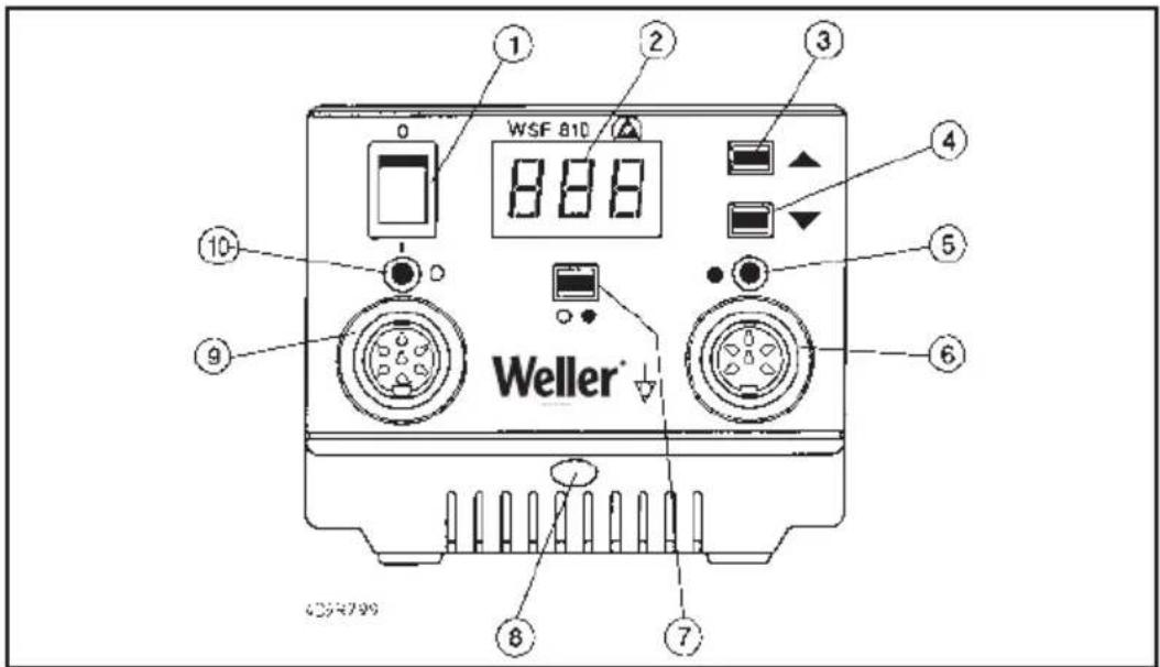
- Netzschalter
- Digitalanzeige
- „UP“ Taste
- „DOWN“ Taste
- Anzeige Kanalwahl / Vorschubfunktion
- Anschlussbuchse Vorschubeinheit
- Kanalwahltaste
- Potentialausgleichsbuchse
- Anschlussbuchse Lötkolben
- Anzeige Kanalwahl / Optische Regelkontrolle Lötkolben
- Verriegelung Deckel Vorschubeinheit
- Anschlussstecker Vorschubeinheit
-
Anschluss für Drahtführung Lötkolben
-
Interrupteur secteur
- Afficheur numérique
- Touche „UP“
- Touche „DOWN“
- Témoin de sélection du canal / fonction d'avance
- Prise pour l'unité d'avance
- Touche de sélection du canal
- Prise d'équipotentialité
- Prise pour le fer à souder
- Témoin de sélection du canal / contrôle visuel de réglage du fer à souder
- Verrouillage couvercle unité d'avance
- Fiche pour l'unité d'avance
-
Connexion pour guide fil du fer à souder
-
Netschakelaar.
- Digitale indicatie.
- „UP“ toets.
- „DOWN“ toets.
- Indicatie kanaal-keuze / vooruitduwfunctie.
- Aansluitbus vooruitduweenheid.
- Kanaalkeuzetoets.
- Equipotentiaalbus
- Aansluitbus soldeerbout.
- Indicatie kanaalkeuze / optische regelcontrole soldeerbout.
- Vergrendeling deksel vooruitduweenheid
- Aansluitsteller vooruitduweenheid.
-
Aansluiting voor draadgeleiding soldeerbout
-
Interruttore di rete
- Display
- Tasto "UP"
- Tasto "DOWN"
- Indicatore selezione canale / Funzione di avanzamento
- Presa di collegamento unità di avanzamento
- Tasto di selezione canale
- Presa di equalizzazione dei potenziali
- Presa di collegamento stilo saldante.
- Indicatore selezione canale / Controllo ottico della regolazione per stilo sadate.
- Chiusura coperchio unità di avanzmeto
- Connettore per unità di avanzamento
-
Collegamento per conduzione filo allo stilo saldante.
-
Main switch
- Digital display
- "Up" key
- "Down" key
- Display for channel selection / feed function
- Socket for feed unit
- Channel selector key
- Equipotential bonding socket
- Socket for soldering iron
- Display for channel selection / optical soldering iron controller
- Locking pin cover (feeder unit)
- Plug for feed unit
-
Connecting the soldering iron wire lead
-
Nätkontakt
- Digital display
- "UP"-tangent
- "DOWN"-tangent
- Indikering val av kanal
- Anslutning frammatningsfunktion
- Tangent för val av kanal
- Potentialutjämningskontakt
- Anslutning för lödkolv
- Indikering av kanalval / visuell regleringskontroll lödkolv
- Låsanordning lock till frammatningsenhet
- Anslutningskontakt för frammatningsenhet
-
Anslutning för lödkolvens trådstyrning
-
Interruptor de red
- Indicación digital
- Tecla «UP» (arriba)
- Tecla «DOWN» (abajo)
- Indicación selección de canal / función de avance
- Manguito de conexión unidad de avance
- Selector de canal
- Manguito de compensación del potencial
- Manguito de conexión soldador
- Indicación selección de canal / control óptico de regulación soldador
- Tapa de cierre de la unidad de avance
- Conector de conexión unidad de avance
-
Conexión para guía de hilo del soldador
-
Netafbryder
- Digitalvisning
- "UP"-taste
- "DOWN"-tast
- Visning kanalvalg / fremførings funktion
- Tilslutningsbøsning fremføringsenhed
- Kanalvalgstast
- Potentialudligningsbøsning
- Tilslutningsbøsning loddekolbe
- Visning kanalvalg / optisk regula tor-kontrol loddekolbe
- Lås låg fremføringsenhed
- Tilslutningsstik fremføringsenhed
-
Tilslutning til loddekolbens trådføring
-
Interruptor geral
- Mostrador digital
- Botão „UP“
- Botão „DOWN“
- Indicação selecção de canal / função de avanço
- Tomada para ligação da unidade de avanço
- Botão de selecção de canal
- Tomada da ligação equipotencial
- Tomada para ligação do ferro de soldar
- Indicação do canal seleccionado/ controlo de regulação óptico para o ferro de soldar
- Travamento da tampa da unidade de avanço
- Conector para a unidade de avanço
-
Ligação para a guia de arame do ferro de soldar
-
Verkkokytkin
- Digitaalinäyttö
- Näppäin UP
- Näppäin DOWN
- Näyttö kanavanvalinta / syöttötoiminto
- Syöttöyksikön liitäntärasia
- Kanavanvalintanäppäin
- Potentiaalintasausrasia
- Juottokolvin liitäntärasia
- Näyttö kanavanvalinta/ juottokolvin optinen säätövalvonta
- Syöttöyksikön kannen lukitus
- Syöttöyksikön liitäntäpistoke
-
Juottokolvin langanohjaimen liitäntä
-
Нлектрикός διακόπτης
- Ψηφιακή ένδειξη
- Плήκτρο „UP“
- Плήκτρο „DOWN“
- Ένδειξη επιλογής καναλιού / Λειτουργία προώθησης
- Συνδετήρια υποδοχή για τη μονάδα προώθησης
- Πλήκτρο επιλογής καναλιού
- Υποδοχή εξίσωσης δυναμικού
- Συνδετήρια υποδοχή για το έμβολο συγκόλλησης
- Ένδειξη επιλογής καναλιού / Οπτικός ρυθμιστικός έλεγχος του εμβόλου συγκόλλησης
- Μανδάλωση καπακιού μονάδας τροφοδοσίας
- Συνδετήριο βύσμα της μονάδας προώθησης
- Σύνδεση οδηγού σύρματος κολλητηριού
4D9R685/1
4D9B6A972
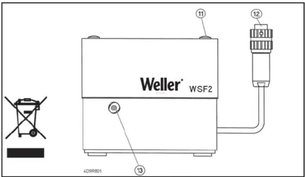
- Netzanschluss
- Netzsicherung
- Anschlussbuchse für externe Auslösung und potentialfreiem Kontakt.
- Klemmschraube für Lötkolbendrahtführung
- Drahteinführung
- Rändelmutter für Zinnrollenbefestigung
- Collegamento a rete
- Fusibile di rete
- Presa di collegamento per dispositivo di azionamento esterno e contatto libero da potenziale
- Vite di bloccaggio per il connettore del tubo per il filo di lega allo stilo saldante.
- Guida per inserimento filo di lega.
-
Dado zigrinato per fissaggio roccetti di stagno.
-
Connecteur secteur
- Fusible secteur
- Prise pour le déclenchement externe et le contact libre de potentiel
- Vis de serrage pour le guide fil du fer à souder
- Entrée du câble
-
Ecrou moleté pour la fixation de la bobine de soudure
-
Main power connection
- Main fuse
- Connecting socket for external triggering and floating contact
- Clamping screw for the soldering iron wire lead
- Wire infeed
-
Knurled nut for attaching older roll
-
Netaansluiting
- Netzekering.
- Aansluitbus voor externe activering en potentiaalvrij contact.
- Klemschroef voor soldeerdraadge leiding
- Draadinvoer.
- Kartelmoer voor bevestiging rol soldeertin.
- Nätanslutning
- Nätsäkring
- Anslutning för extern utlösning och potentialfri kontakt
- Låsskruv för lödkolvens trådstyrning
- Trådinmatning
-
Räfflad mutter för fastsättning av tennrulle.
-
Conexión de red
- Fusible
- Manguito de conexión para activación externa y contacto libre de potencial
- Tornillo de fijación para guía de
hilo del soldador
18 Pasa-hilos - Tuerca moleteada para sujetar el rollo de estaño
- Verkkoliitäntä
- Päävirtapiirikatkaisin
- Liitäntärasia ulkoiselle laukaisulle ja potentiaalivapaalle koskettimelle
- langenohjaimen lukitusruuvi
- Langanohjaus
- Pyälletty mutteri tinarullan kiinnitykseen
- Sítová přípojka
15 Sítová pojistka - Připojovací zásuvka pro externí spínání a bezpotenciálový kontakt.
- Stahovací šroub pro vedení drátu páječky
- Zavedení drátu
- Rýhovaná matice pro upevnění cívky cínu
- Sietová prípojka
- Sietový istič
- Pripojovacia zásuvka pre externé spínanie a bezpotenciálový kontakt.
- Zaisťovacia skrutka pre vedenie drôtu spájkovačky
- Zavedenie drôtu
- Vrúbkovaná matica na upevnenie zvitku s cínom
- Lizdas elektros tinklui prijungti
- Tinklo saugiklis
- Prijungimo lizdas išoriniam jjungimui ir nepotencialiniam kontaktui.
- Lituoklio vielos kreipiamosios fiksavimo varžtas
- Vielos jvadas
-
Veržlė alavo ritinėliui tvirtinti
-
Nettilslutning
- Netsikring
- Tilslutningsbøsning til ekstern udløsning og potentialfri kontakt
- Klemskrue til loddekolbens trådføring
- Trådåbning
-
Fingermøtrik til fastgørelse af tinrullen
-
Σύνδεση στο ηλεκτρικό δίκτυο
- Ασφάλεια ηλεκτρικού δικτύου
- Συνδετήρια υποδοχή για εξωτερική ενεργοποίηση και για ελεύθερη δυναμικού επαφή
- Βίδα συγκράτησης οδηγού σύρματος κολλητηριού
- Εισαγωγή σύρματος
-
Αυλακωτό περικόχλιο για τη στερέωση του καρουλιού κασσιτέρου
-
Przyłącze sieciowe
- Bezpiecznik sieciowy
- Gniazdo przyłączeniowe dla zewn trznego wyzwolenia i bezpotencjałowego złącza.
- Sruba zaciskowa dla prowadnika lutowia
- Prowadnik lutowia
-
Nakr tka radełkowa dla mocowania szpuli z cyną
-
Omrežni priključek
- Omrežna varovalka
- Priključna doza za zunanje aktiviranje in kontakt brez potenciala.
- Privojni vijak za vodilo žice spajkalnika
- Vodilna odprtina
-
Narebričena matica za pritrditev koluta z žico
-
Pieslēgums tīklam
- Elektrības tīkla drošības elements
- Pieslēguma bukse ārējai iedarbināšanai un bezpotenciāla kontaktam.
- Fiksācijas skrūve lodāmura stieples vadotnei
- Stieples ievade
-
Regulējami uzgriežni alvas rituļa nostiprināšanai
-
Ligação à rede
- Fusível de rede
- Tomada para ligação do disparo externo e contacto isen to de potencial
- Parafuso de fixação para a guia
de arame do ferro de soldar
18 Entrada de arame -
Porca serrilhada para a fixação do rolo de estanho
-
Şebeke bağlantısı
- Şebeke sigortası
- Harici devreye alma ve potansiyel bakımından serbest kontak için bağlantı fiş yuvası.
- Lehim havyası kablo bağlantısı için klemens vidası
- Kablo bağlantısı
-
Lehim makarasını sabitlemek için tırtıllı somun
-
hálózati csatlakozás
- hálózati biztosíték
- külső kioldó és pontenciálmentes érintkező csatlakozóhüvelye
- forrasztópáka drótvezetőjének rögzítőcsavarja
- drótbevezetés
-
recézett anyag az óntekercs rögzítésére
-
Vörgupistik
- Võrgukaitse
- Välise sisselülitamise ja potentsiaalivaba kontakti ühenduspuks.
- Jootekolvi traadijuhiku klemmkruvi
- Traadi sisseviik
-
Tinarullikinnituse mutter
-
Букса за включване в мрежата
- Мрежов предпазител
- Съединителната букса за външно задействане и без потенциал Контакт.
- Затегателен винт за теловоденето на поялника
- Теловодене
-
Гайка с назъбка за Закрепване за макара калаен припой
-
Racord la retea
- Siguranță de rețea
- Mufă de conectare pentru declanșare externă și contact fără potential.
- Şurub de blocare pentru ghidarea sârmei pentru ciocanul de lipit
- Intrarea sârmei
-
Piuliță striată pentru fixarea rolelor de cositor
-
Mrežni priključak
- Mrežni osigurač
- Utičnica za vanjsko oslobadanje i bespotencijalni kontakt.
- Stezni vijak za upravljanje lemilom žicom
- Unos žice
- Narezna matica za pričvršćivanje rolne od kositra
Modus SFA automatic:
Modus SFC continuous:
natural_image
Product photo of a small electronic device with a brush, a small container, and a cylindrical item (no visible text or symbols)4. Inbetriebnahme
Dimensions (L X P X H): 120 X 217 X 199 mm
natural_image
Product photo of a soldering iron shaver with a brush and small sample (no visible text or symbols)4. Mise en service
Modus SFA automatic:
Modus SFC continuous:
natural_image
Assorted items including a toothbrush, toothpaste brush, and a small container with a textured surface (no visible text or symbols)4. Inbruikname
Soldeertinrol monteren
Dimensioni (Largh. X Prof. X Alt.): 120 X 217 X 199 mm
natural_image
Product photo of a soldering iron shaver with accessories (no visible text or symbols)Thank you for placing your trust in our company by purchasing the WELLER soldering station WSF 81 D5/D8. Production was based on stringent quality requirements which guarantee the perfect operation of the device.

1. Caution!
Please read these Operating Instructions and the attached safety information carefully prior to initial operation. Failure to observe the safety regulations results in a risk to life and limb.
The manufacturer shall not be liable for damage resulting from misuse of the machine or unauthorised alterations.
The WELLER soldering station WSF 81 D5/D8 corresponds to the EC Declaration of Conformity in accordance with the basic safety requirements of Directives 2004/108/EC, 2006/95/EC and 2011/65/EU (RoHS).
2. Description
The soldering station WSF 81 D5/D8 is part of a family of units developed for industrial production technology, repair work and laboratory applications.
The soldering station contains an automatic filler wire feed system. The diameters of filler wire that can be used are divided into two ranges and are determined by the type of soldering iron used (0.5 mm – 0.8 mm for the WSF P5 soldering iron and 0.8 mm – 1.5 mm for the WSF P8 soldering iron). The feed unit and control unit can be stacked to save space.
The control unit contains digital electronics for controlling the soldering iron control unit (Channel 1) and the feed control unit (Channel 2). A microprocessor is used to obtain the best possible temperature control response with different soldering tools and precise feed control of the solder wire.
The temperature at the tip of the soldering iron (Channel 1) is displayed digitally and can be smoothly adjusted within a range of 50^ C - 450^ C. A blinking red LED in the display is used as a visual control check to signal that the preselected temperature has been reached. A continuous signal indicates that the system is heating.
An integrated temperature monitoring circuit is used to evaluate various temperature states via a floating contact.
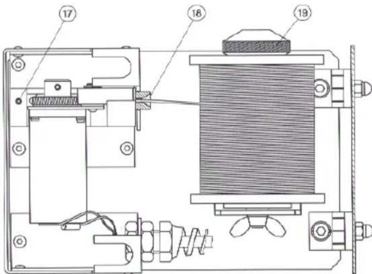
The feed unit contains the mechanical drive for the solder feed and the soldering iron connection for the wire lead. A wire holder that holds up to 1 kg of filler wire (max.) is also included in the feed unit.
The mechanical drive adjusts automatically to the diameter of the wire.
The WSF soldering iron features an ergonomic design and a movable heating element. The very powerful 80W heating element ensures that the soldering temperature is reached quickly and precisely. The angle of the movable heating element can be adjusted at approximately 40^ after loosening the locking bolt (20).
A general distinction is made between two types of solder feed system:
Mode SFA - automatic:
In the operation mode SFA, the preset quantity of solder is fed by the activation of the finger switch (optional: pedal switch or external contact). The required amount of solder can be smoothly adjusted from approx. 1 – 10mm. The feed interval (Channel 2) is shown digitally.
Mode SFC - continuous:
In the operating mode SFC, the solder feed is activated for as long as the finger switch (optional: pedal switch or external contact) is activated. The speed of the feed rate can be smoothly adjusted and is shown digitally on Channel 2.
Various equipotential bonding possibilities for the soldering tip, zero voltage, and the antistatic design of the soldering station complete the high standard of quality of this unit.
Additional functions and settings are possible at the soldering station using the optional input devices WCB1 and WCB2. An integrated temperature gauge and PC interface are included in the expanded scope of function of the input device WCB2.
3. Operation and settings
Channel selection
The digital display can be set to Channel 1 (temperature control) or Channel 2 (feed) by pressing the channel selection key (7). The channel that is currently displayed is marked by a red/orange LED above the socket (6) or (9).
If no keys have been activated, the unit will switch automatically to Channel 1 after approx. 10 sec and show the actual temperature.
Temperature setting (Channel 1)
If no keys have been pressed, the digital display (2) will show the actual temperature. Pressing the "Up" or "Down" key (3) (4) will switch the digital display (2) to the current setpoint value. The setpoint value (blinking display) can be changed in the desired direction by touching or continuously pressing the "Up" or "Down" key (3) (4).
Technical specifications
Dimensions (l x w x h): 120 X 217 X 199 mm
Supply voltage: 230 V / 50Hz
Output voltage: 24 VAC (Channel 1); 24 VDC (Channel 2)
Power: 90 W
Fuse: T800 mA
Temperature control: stepless 50 °C – 450 °C
Accuracy: + - 9°C
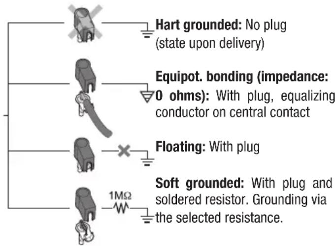
Equipotential bonding: Initial state: hard grounded
If the key is pressed continuously, the setpoint value will change rapidly. The digital display (2) will automatically return to the actual value approximately 2 seconds after the key is released.
Standard setback
If the soldering tool is not used within a period of 20 minutes the temperature will be automatically reduced to a standby temperature of 150 °C (300 °F). After three setback periods (60 min.) the "AUTO OFF" function will be activated and the soldering iron will be switched off.
Activating the standard setback function: When switching on the unit press the "UP" button until "ON" appears in the display. Use the same process to switch the unit off. "OFF" will appear in the display (state upon delivery).
The use of very fine soldering tips may have a negative effect on reliable function.
Feed setting (Channel 2)
After switching to Channel 2, the digital display (2) will show the speed in the SFC mode or the feed period in the SFA mode. This value can be changed in the desired direction by touching or continuously pressing the "Up" or "Down" key (3) (4). If the key is pressed continuously, the setpoint value will change rapidly. If no keys are pressed, the unit will automatically switch to Channel 1 after approximately 10 seconds and show the actual temperature.
Setting range:
SFA mode – feed period (solder)
1 - 300 (10ms intervals)
SFC mode - speed
10% - 100%
Rapid feed:
Simultaneous pressing of the "UP" and "DOWN" keys advances the solder wire at max. speed (100%). Recommended for advancing the filler wire after the solder roll is replaced.
SFA / SFC mode switch:
Press the channel selection key (7) continuously and set the desired mode with the "UP" key (3). The new operating mode will appear on the display.
Adjusting the temperature window
Press the channel selection key (7) and "Down" (4) simultaneously. The blinking value (in °C/°F) of the current temperature window will appear on the display (factory-set to "000").
The factory setting "000" means:
Temperature monitor circuit has been switched off and the unpowered contact (16) is always low-resistant.
°C display
The setting "001 - 099" corresponds to the following: Size of the temperature window + - 1^ to + - 99^
°F display
The setting "001 - 178" corresponds to the following: Size of the temperature window + - 1^ to + - 178^
Unpowered contact (potential independence)
If the actual temperature of the soldering tool is within the temperature window (tolerance width), the contact (16) will be low-resistant. If the temperature is outside the temperature window, this will be indicated on the display (2) as "HI" (temperature too high) or "LO" (temperature too low) at 2 second intervals. The contact (16) is high-resistant.
The transistor output of an optocoupler functions as the unpowered contact of the unit. Care must therefore be taken to note the polarity of the voltage to be applied.
PLUS (+) at Pin 2
MINUS (-) at Pin 3
This contact can be loaded with max. 24V / 20mA
External input device WCB 2 (optional)
The following functions are available when using an external input device:
Offset:
The actual temperature of the soldering tip can be changed by + - 40°C by entering a temperature offset
Setback:
Reduction of the setpoint temperature to 150^ C /300°F (standby). The setback period, after which the soldering station switches to the standby mode, can be adjusted from 0 – 99 minutes. The setback state is indicated by a blinking display of the actual value. After three setbacks, the AUTO OFF function will be activated and the soldering tool will switch off (blinking dash on the display). The setback state or AUTO OFF ends after pressing a key or the finger switch. At this time the setpoint will be displayed briefly.
Lock:
Locking of the setpoint temperature and temperature window. No changes can be made to the soldering station settings after locking.
°C / °F:
Switching the temperature display from °C to °F and vice versa. Pressing the "Down" key when switching the unit on will show the current temperature version.
Window:
Limitation of the temperature range to max. ±99 ^ based on a locked temperature resulting from the "LOCK" function. The locked temperature represents the median point of the adjustable temperature range.
For units with a floating contact (optocoupler output) the "WINDOW" function is used to adjust a temperature window. If the actual temperature is within the temperature window the floating contact will be enabled (optocoupler output).
Cal:
Factory setting FSE (reset of all adjusted values to 0, temperature setpoint value: 350^ C/660°F
PC interface:
RS232 (WCB 2 only)
Temp.gauge:
Integrated temperature gauge for thermocouple Type K (WCB 2 only)
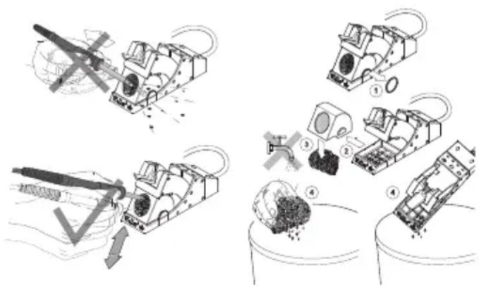
Maintenance and care
If the feed rate is irregular, the drive wheel can be cleaned with a brass brush. First remove the control unit from the feed unit. Push back the cover of the feed unit to access the feed unit. Lift the drive wheel and clean.
Instructions for care of the WSF P5/P8 / WP / WSP
soldering gun (heating element, tip receptacle and soldering tip)
Please clean the heating element depending on how much you use the soldering gun.
natural_image
Product photo of a soldering iron kit with a sample holder, a tool, and a small sample (no visible text or symbols)Cleaning the heating element:
Remove any dirt and old solder from the tip of the gun. Remove the tip receptacle by undoing the knurled nut/tip receptacle. Take care not to crush the tip receptacles during removal (in order to avoid damaging the heating elements).
Use wire brush T0051382799 for cleaning
Cleaning set WDC 2 T0051512699
Cleaning set WDC T0051512799.
Care of the soldering tip:
After lead-free soldering we recommend that you always rewet the soldering tip with tin solder before putting the soldering gun back into the stand. Always use our steel wool for WDC 2 T0051512599 and WDC T0051512499 to clean the soldering tip. We recommend using Tip Activator (T0051303199) for non-wettable soldering tips.
4. Start-up
Establish the electrical connection between the feed unit and the control unit. Insert plug (12) into socket (6).
Connect the soldering iron connections to the control unit and feed unit. Insert the electrical connecting plug for the soldering iron into the 7-pin socket (9) of the control unit, and lock into place. Fully insert the wire lead into the connection element (13) of the feed unit and fasten with the clamping screw (17).
Place the soldering iron in the storage tray.
Verify the correct system voltage and connect the control unit to the mains (14). Switch on the unit (1).
Install solder roll.
Remove knurled nut (19) on the solder roll holder. Place the solder roll on the shaft so that the wire unrolls downwards. Secure the roll with the knurled nut and push the end of the wire into the inlet port (18).
Pressing the "UP" and "DOWN" keys simultaneously will cause the drive to catch the solder wire and transport the wire at maximum speed. Continue to advance the solder wire until it appears at the soldering iron nozzle (22).
In the event that the solder wire is not caught by the drive, the cover of the feed unit can be pushed back to access the drive unit. Therefore turn both locking pins (10) counter clock wise (ccw) approx. 90° until release.
Carry out adjustments to the units as described in the section "Operation and settings".
5. Equipotential bonding
Four different versions can be obtained by different wiring of the 3.5mm jack bushing (8).
6. Soldering instructions
For initial heating coat the soldering tip (tip can be coated selectively) with solder. This removes oxide deposits and impurities from the soldering tip that occur during storage. During soldering breaks and before storing the soldering iron, always ensure that the soldering tip is well coated with solder. When using very low activated flux agents (no clean), the use of "Tip Activator" is recommended to maintain the coating. Dirt, foreign material or damage may not affect the transition between the heating element/sensor and the soldering tip.
This will compromise the precision of the temperature control.
Important: always ensure the soldering tip fits properly.
Keep the heat-conducting surfaces of the heating element and soldering tip clean.
The hot soldering tip may not come in contact with the cleaning sponge or plastic surfaces.
These soldering units have been adjusted for use with a medium-sized soldering nozzle or jet. Deviations can occur as a result of changing the tip or using other tip shapes.
7. Accessories
| 005 13 120 99 | Pedal switch |
| 005 13 031 99 | Tip Aktivator |
| 005 28 126 99 | FE-attachment |
Soldering tips:
| 005 44 403 99 LT A | 1.6 mm chisel |
| 005 44 405 99 LT B | 2.4 mm chisel |
| 005 44 407 99 LT C | 3.2 mm chisel |
| 005 44 443 99 LT ALX | 1.6 mm bent |
| 005 44 442 99 LT BX | 2.4 mm bent |
| 005 44 412 99 LT H | 0.8 mm chisel |
| 005 44 420 99 LT HX | 0.8 mm bent |
| 005 44 408 99 LT F | 1.2 mm round, slanted |
| 005 44 444 99 LT BB | 2.4 mm round, slanted |
| 005 44 445 99 LT CC | 3.2 mm round, slanted |
8. Scope of supply
Soldering station WSF 81 D5/D8
Control unit
Feed unit
WSF P soldering iron
Small tool
Soldering iron storage
Power cord
Operating instructions
Safety Information
Subject to technical change without notice!
See the updated operating instructions at www.weller-tools.com.
Modus SFA automatic:
Modus SFC continuous:
natural_image
Product photo of a soldering iron kit with a sample holder, tool, and base (no visible text or symbols)natural_image
Product photo of a black plastic tray with a brush and small accessories (no visible text or symbols)Modus SFA automatic:
Modus SFC continuous:
natural_image
Product photo of a small electronic device with a brush, a small container, and a small cylindrical item (no visible text or symbols)4. Idrifttagning
Loddestation WSF 81 D5/D8
Styreenhed
fremføringsenhed
WSF P loddekolbe
små stykker værktøj
loddekolbeholder
Netkabel
Driftsvejledning
Modo SFC continuous:
natural_image
Product photo of a black electronic device with a brush and small accessories (no visible text or symbols)natural_image
Two technical diagrams showing a helicopter with directional arrows indicating motion or force (no text or symbols present)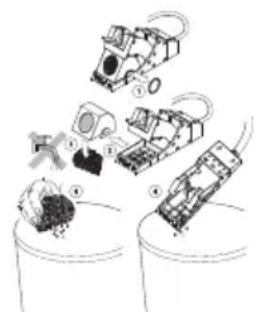
natural_image
Illustration of robotic devices and mechanical components in a container (no text or symbols)SFC continuous-tila:
natural_image
Product photo of a black electronic device with a brush and accessories (no visible text or symbols)natural_image
Two technical diagrams showing a mechanical device with rotating components and a downward arrow indicating motion (no text or symbols)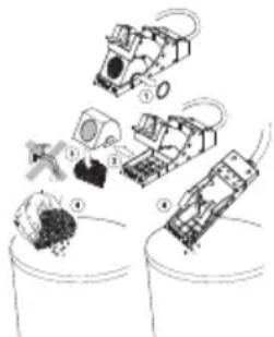
natural_image
Illustration of robotic devices interacting with a container (no text or symbols)4. Käyttöönotto
natural_image
Product photo of a soldering iron shaver with accessories (no visible text or symbols)WSF P5/P8 / WP / WSP
natural_image
Black plastic tray holding a small tool and a small container with granular material (no text or symbols visible)4. Devreye alma
natural_image
Product photo of a black box with decorative items and a tool, no visible text or symbolsTryb SFC continuous:
Wymiary (SZER. X GL. X WYS.): 120 X 217 X 199 mm
natural_image
Assorted small electronic components including a black box with internal components and a tool, arranged on a white surface (no text or symbols visible)4. Uruchomiene
natural_image
Product photo of a black electronic device with a brush and accessories (no visible text or symbols)4. Üzembevétel
natural_image
Product photo of a black electronic device with a screwdriver and small accessories (no visible text or symbols)Čistenie vyhrievacieho telesa:
Način SFA automatic:
Način SFC continuous:
natural_image
Product photo of a small electronic device with a brush, a small container, and a small cylindrical component (no visible text or symbols)4. Pred uporabo
RS232 (ainult WCB 2)
Temperatuuri-mōōteseade:
natural_image
Product photo of a small electronic device with a brush, a small container, and a coin on top (no visible text or symbols)4. Kasutuselevõtt
natural_image
Product photo of a small mechanical tool with a textured knob, next to a black plastic container and a small cylindrical component (no visible text or symbols)Kaitinimo elemento valymas:
4. Pradedant naudoti
natural_image
Product photo of a soldering iron shaver with a brush and small accessories (no visible text or symbols)4. Lietošana
natural_image
Black box with textured lid and tool, accompanied by a small container and a small cylindrical object (no visible text or symbols)Modul SFC continuous:
natural_image
Product photo of a black electronic device with a brush and accessories (no visible text or symbols)natural_image
Product photo of a black electronic device with a textured lid, a small container, and a tool (no visible text or symbols)Održavanje vrha lemila:
4. Puštanje u pogon
Jedinicu punjenja povezati električki s kontrolnom jedinicom. Utikač (12) u utičnici (6).
Priključke lemila povezati s kontrolnom jedinicom i jedinicom punjenja. Električni priključak lemila umetnuti u 7 pol. utičnicu (9) kontrolne jedinice i zaključati. Umetnuti žicu u priključak (13) jedinice punjenja do zaustavljanja i steznim vijkom (17) fiksirati.
Odložite lemilo u zaštitni stalak.
Kod pravilnog napajanja spojiti kontrolnu jedinicu na mrežu(14). Uključiti uređaj (1).
Montirati rolu kositra
Maticu (19) držača role kositra demontirati. Rolu kositra staviti tako na vratilo da je lem savijen prema dolje. Rolu kositra pričvrstiti s maticom i lem ugurati u otvor (18).
Istovremenim pritiskom "UP" i "DOWN" tipkom pogon prepoznaje lem i prenosi ga maks. brzinom.
Prenositi lem do pojavljivanja na mlaznici lemila (22).
Poklopac jedinice punjenja se može preklopiti natrag kako bi pogonska jedinica bila dostupna, u slučaju da pogon ne prepoznaje lem. Dva elementa zaključavanja na poklopcu mogu se otvoriti rotacijom u lijevo za 90°.
Zatim podesiti uređaj kako je opisano u odlomku “Rad i podešavanje”.
-
Arretierschraube für Heizkörperverstellung
-
Klemmschraube für Zuführrohr
-
Zuführrohr
-
Vis de blocage pour le réglage de l'élément chauffant
-
Vis de blocage pour le tube d'amenée
-
Tube d'amenée
-
Vastzetschroef voor instelling warmtelichaam.
-
Klemschroef voor toevoerbuis.
-
Toevoerbuis.
-
Vite di bloccaggio per regolazione della posizione resistegnza.
-
Vite di bloccaggio per tubo di convogliamento
-
Tubo di convogliamento
-
Locking screw for heater adjustment
-
Clamping screw for feed line
-
Feed line
-
Låsskruv för värmareinställning
-
Låsskruv för tillförselrör
-
Tillförselrör
-
Tornillo de bloqueo para el ajuste del radiador
-
Tornillo de sujeción para tubo de alimentación
-
Tubo de alimentación
-
Låseskrue til indstilling af varmelegemet
-
Klemskrue til tilførselsrør
-
Tilførselsrør
-
Parafuso de retenção para a regulação do elemento térmico
-
Parafuso de aperto para o tubo de alimentação
-
Tubo de alimentação
-
Lämmittimen säädön lukitusruuvi
-
Syöttöputken kiristysruuvi
-
Syöttöputki
-
Σταθεροποιητική βίδα για τη μεταρρύθμιση του θερμαντικού σώματος
-
Συνδετήρια βίδα για τον τροφοδοτικό σωλήνα
-
Τροφοδοτικός σωλήνας
-
Isitici kısmının ayarını yapmak için kilitleme vidası
-
Giriş borusu için klemens vidası
-
Giriş borusu
-
Aretační šroub pro nastavení t opného tělesa
-
Stahovací šroub pro přívodní t rubici
-
Přívodní trubice
-
Śruba regulacyjna dla ustawia nia elementu grzejnego
-
Śruba zaciskowa dla rury doprowadzającej
-
Rura doprowadzająca
-
fütötestállítás rögzítőcsavarja
-
bevezetőcső rögzítőcsavarja
-
bevezetőcső
-
Aretovacia skrutka na prestave nie vyhrievacieho telesa
-
Zaistovacia skrutka na prívodnú rúrku
-
Prívodná rúrka
-
Zaporni vijak za premikanje grelnega telesa
-
Privojni vijak za dovodno cev
-
Dovodna cev
-
Küttekeha regulaatori kinnitus kruvi
-
Juurdeviigutoru klemmkruvi
-
Juurdeviigutoru
-
Kaitinimo elemento reguliavimo varžtas
- Padavimo vamzdelio fiksavimo varžtas
- Padavimo vamzdelis
20.Фиксиращвинтза регулиранена нагревателнияелемент
21.Затегателенвинтза подаващататръба
22.Подаващатръба - Sigurnosni vijak za prilagođavanje grijaćeg elementa
- Stezni vijak za cijev napajanja
-
Cijev napajanja
-
Stiprinājuma skrūve sildkermena pārstatīšanai
- Fiksācijas skrūve pievades cau rulei
- Pievades caurule
- Șurub de blocare pentru ajustarea corpului de încălzire
- Šurub de prindere pentru teava de alimentare
- Teavă de alimentare

Symbole

CE mark of conformity British Conformity Mark

Disposal
Waste light sources have to be removed from equipment. Check with your local authority or retailer for recycling advice and collection point. According to local regulations retailers may have an obligation to take back waste electrical and electronic equipment free of charge. Your contribution to re-use and recycling of waste electrical and electronic equipment helps to reduce the demand of raw materials. Waste electrical and electronic equipment contain valuable, recyclable materials, which can adversely impact the environment and the human health, if not disposed of in an environmentally compatible manner. Delete personal data from waste equipment, if any.
Contaminated filters must be treated as special waste. Dispose of replaced equipment parts, filters or old devices in accordance with the rules and regulations applicable in your country.

Símbolos

ENC declaration of conformity
We hereby declare that the products described herein comply with the following guidelines:
EN UK declaration of conformity
We hereby declare that the products described herein comply with the following guidelines:
2014/35/EU, 2014/30/EU, 2011/65/EU SI 2008 No.1597, SI 2016 No.1091, SI 2012 No.3032
CE Besigheim, 2024-08-01
Philippe Buidin
Managing director
Authorised to compile technical documentation.
Authorised to compile technical documentation.
Apex Tool Group UK Ltd Registered in England,
Company Number 14127816
Registered Office: C/O TMF Group 13th Floor,
One Angel Court, London, EC2R 7HJ,
United Kingdom
GERMANY
Weller Tools GmbH
Carl-Benz-Str. 2
74354 Besigheim
Phone: +49 (0) 7143 580-0
Fax: +49 (0) 7143 580-108
GREAT BRITAIN
Apex Tool Group
(UK Operations) Ltd
4th Floor Pennine House
Washington, Tyne & Wear
NE37 1LY
Phone: +44 (0) 191 419 7700
Fax: +44 (0) 191 417 9421
FRANCE
Apex Tool France S.N.C.
25 Av. Maurice Chevalier BP 46
77832 Ozoir-la-Ferrière, Cedex
Phone:+33 (0) 1.64.43.22.00
Fax: +33 (0) 1.64.43.21.62
ITALY
Apex Tool S.r.l.
Viale Europa 80
20090 Cusago (MI)
Phone: +39 (02) 9033101
Fax: +39 (02) 90394231
SWITZERLAND
Apex Tool Switzerland Sàrl
Apex Tools - Australia
P.O. Box 366
519 Nurigong Street
Albury, N. S. W. 2640
Phone: +61 (2) 6058-0300
Fax: +61 (2) 6021-7403
CANADA
Apex Tools - Canada
7631 Bath Road, Mississauga
Ontario L4T 3T1
2nd Floor, Area C, 177 Bi Bo Road
Pudong New Area
Shanghai 201203
Phone: +86 (21) 60 88 03 20
USA
Apex Tool Group, LLC
1000 Lufkin Road
Apex, NC 27539
Fax: +1 (919) 387-2639
T005 56 706 08 / 06.2016
T005 56 706 07 / 10.2013
Product Registration
www.weller-tools.com/registration

GERMANY
Weller Tools GmbH
Carl-Benz-Straße 2
74354 Besigheim
Tel: +49 (0) 7143 580-0
CHINA
Apex Tool Group
Room 302A,
NO 177 Bibo Road
Shanghai, 201202
Tel: +86 (21) 60880288
info@weller-tools.com
www.weller-tools.com
THE NETHERLANDS
Apex Tool Group B. V.
Apex Tool Group UK Ltd
Registered in England,
Company Number 14127816
Registered Office:
C/O TMF Group 13th Floor,
One Angel Court, London,
EC2R 7HJ, United Kingdom
Tel: +44 740 8836 404
USA
Apex Tool Group, LLC.
Weller Professional Tools Division
1000 Lufkin Road
Apex, NC 27539
Tel: +866 -498- 0484
Weller