Modul ROLOC PLUS - Plumbing tool ROTHENBERGER - Free user manual and instructions
Find the device manual for free Modul ROLOC PLUS ROTHENBERGER in PDF.
User questions about Modul ROLOC PLUS ROTHENBERGER
0 question about this device. Answer the ones you know or ask your own.
Ask a new question about this device
Download the instructions for your Plumbing tool in PDF format for free! Find your manual Modul ROLOC PLUS - ROTHENBERGER and take your electronic device back in hand. On this page are published all the documents necessary for the use of your device. Modul ROLOC PLUS by ROTHENBERGER.
USER MANUAL Modul ROLOC PLUS ROTHENBERGER
natural_image
Illustration of a mechanical device with a spring and lever mechanism (no text or symbols)EN Instructions for use
text_image
Warning symbol and icon: triangular warning sign with exclamation mark next to person reading a documentIntro
EU-DECLARATION OF CONFORMITY
We declare on our sole accountability that this product conforms to the standards and guidelines stated.
DECLARATION EU DE CONFORMITÉ
authorized representative signature

ppa. Thorsten Bühl Kelkheim, 18.04.2016
Director Corporate Technology
D-65779 Kelkheim/Germany
Intro
| DEUTSCH | Seite 2 |
| Bedienungsanleitung bitte lesen und aufbewahren! Nicht wegwerfen!Bei Schäden durch Bedienungsfehler erlischt die Garantie! Technische Änderungen vorbehalten! | |
| ENGLISH - Original User ManualPlease read and retain these directions for use. Do not throw them away! The warranty does not cover damage caused by incorrect use of the equipment! Subject to technical modifications! | page 14 |
| FRANÇAIS | page 25 |
| Lire attentivement le mode d'emploi et le ranger à un endroit sûr! Ne pas le jeter ! La garantie est annulée lors de dommages dûs à une manipulation erronée ! Sous réserve de modifications techniques! | |
| ESPAÑOL | página 37 |
| ¡Por favor, lea y conserve el manual de instrucciones! ¡No lo tire! ¡En caso de daños por errores de manejo, la garantía queda sin validez! Modificaciones técnicas reservadas! | |
| ITALIANO | Pagina 49 |
| Per favore leggere e conservare le istruzioni per l'uso! Non gettarle via! In caso di danni dovuti ad errori nell'uso, la garanzia si estingue! Ci si riservano modifiche tecniche! | |
| NEDERLANDS | bladzijde 61 |
| Lees de handleiding zorgvuldig door en bewaar haar goed! Niet weggooien! Bij schade door bedieningsfouten komt de garantieverlening te vervallen! Technische wijzigingen voorbehouden! | |
| PORTUGUES | pagina 73 |
| Queiram ler e guardar o manual de instruções! Não deitar fora! Em caso de avarias por utilização incorrecta, extingue-se a garantia! Reservado o direito de alterações técnicas! | |
| DANSK | side 85 |
| Læs betjeningsvejledningen, og gem den til senere brug! Smid den ikke ud! Skader, som måtte opstå som følge af betjeningsfejl, medfører, at garantien mister sin gyldighed! Ret til tekniske ændringer forbeholdes! | |
| SVENSKALäs igenom bruksanvisningen och förvara den väl! Kasta inte bort den! Garantin upphör om apparaten har använts eller betjänats på ett felaktigt sätt! Med reservation för tekniska ändringar! | sida 96 |
| NORSKLes bruksanvisningen og oppbevar den vel! Ikke kast den! Oppstår skader på grunn av betjeningsfeil opphører garantiens gyldighet! Tekniske forandringer forbeholdes! | side 107 |
| SUOMILue ja säilytä tämä käyttöohje! Älä heitä pois!Takuu ei kata käyttövirheistä aiheutuvia vahinkoja! Oikeudet teknisiin muutoksiin pidätetään! | sivulta 118 |
| POLSKI | strony 129 |
| Instrukcjê obsługi prosze przeczytac i przechowac! Nie wyrzucac!Przy uszkodzeniach wynikajacych z blédów obsługi wygasa gwarancja! Zmiany techniczne zastrzezone! | |
| CESKY | Stránky 141 |
| Navod k obsluze si prosim přečtěte a uschovejte jej! Nevyhazujte jej!V pripade poškozeni zpusobenem chybnou obsluhou zanika zaruka! Technicke změny jsou vyhrazeny! | |
| TÜRKÇE | sayfa 152 |
| Kullanim açıklamalarini lütfen dikkatlice okuyunuz ve bir yerde muḥafaza ediniz! Çöpe atmayiniz!Kullaniminda yapılan hatalar, garantinin silinmesine neden olur! Teknik deðipiklikler yapma hakkimiz saklidir! | |
| MAGYAR | oldaltól 163 |
| Kérjük, olvassa el és őrizze meg a kezelési utasítást! Ne dobja el!A helytelen kezelésböl származó károsodások esetén megszůnik a jótállás! Můszaki változtatások fenntartva! | |
| ΕΛΛΗΝΙΚΑ | Σελίδα 175 |
| Οδηνίες χειρισμού παρακαλείσθε να τις διαβάσετε και να τις φυλάσσετε! Μην τις πετάξετε!Σε ζημιες από σφάλματα χειρισμού παυει να ισχύει η εγγύηση! Με επιρύλαξη για техνικές αλλαγές! | |
| PYCCΚΙЙ | Страница 187 |
| Прочтите инструкцию по эксплуатации и сохраняйте её для дальнейшего использования! В случае поломки инструмента из-за несоблюдения инструкции клиент теряет право на обслуживание по гарантии! Возможны технические изменения! | |
| 日本語 | ページ 200 |
| 操作説明書は目を通したあと、保管してください!捨ててはいけません!操作を誤ったために生じた損害に対しては、保証は行ないません!本装置に対する技術上の変更により説明書の内容に一致しない場合があります! | |
Inhalt Seite
Temperatur 0°C to 40°C (32°F to 104°F)
natural_image
Three black-and-white product photos: a handheld device, a vertical pole-mounted device, and an open case with tools (no visible text or symbols)natural_image
Two black medical or scientific devices, one with a display and the other labeled 'ROTHENBERGER' (no visible text beyond branding)natural_image
Two medical or industrial devices with directional arrows indicating movement or force (no visible text or symbols)text_image
ROTHENBERGER S/N 1002000001 www.ROTHENBERGER.COM Industments, P 50779 Rothenzer Germanynatural_image
Black handheld electronic device with a screen and control buttons (no visible text or symbols)
Tiefenmessung
text_image
512 AUTO 10 inBild 7 – Tools-Menü
text_image
ROTHENBERGER Vers. 4.11www.rothenberger.com.
14. Kundendienst
1.1 Safety Instructions 15
1.2 General Safety Rules 15
2. Technical Data 17
3. Function of the unit 17
3.1 Description 17
3.2 Standard Equipment 17
3.3 Installing ROSCOPE 1000/i2000 Imager / Module ROLOC PLUS 18
3.4 To Install Module ROLOC PLUS 19
3.5 Tool Inspection 19
3.6 Tool and Work Area Set-Up 19
4. Operating Instructions 19
5. Navigation Buttons 20
6. On-Screen Icons / Settings and Navigation 20
6.1 Locating Screen Display 20
6.2 Tools / Menu 20
7. On Screen Navigation 21
8. Live Screen - Line Detection (ROSCOPE 1000/i2000 w/ ROLOC PLUS) 21
9. Cleaning Instruction 22
- Storage 22
- Troubleshooting 23
- Accessories 24
- Disposal 24
- Customer service 24
Markings in this document:

Danger!
This sign warns against the danger of personal injuries.

Caution!
This sign warns against the danger of property damage and damage to the environment.

Call for action
This product is covered by: U.S. Patents 7,384,308; 7,431,619 B2; 7,581,988 B2; 7,584,534; Chinese Patents: ZL200620147826.1; ZL200620147827.6; ZL2007200004596.8; and other patents pending.
1. Safety Notes
1.1 Safety Instructions
ROSCOPE 1000/i2000 Handheld Inspection Device Safety
- Do not use in explosive atmospheres such as in the presence of flammable liquids, gases, or heavy dust.
- Do not expose to corrosive chemicals.
- The imager is water-proof to 9m depth however the use of the handheld device should be limited to dry environments (as it is not water proof).
1.2 General Safety Rules
WARNING! Read all instructions.
Failure to follow all instructions listed below may result in electric shock, fire and/or serious injury. The term „power tool“ in all of the warnings listed below refers to your mains operated (corded) power tool or battery operated (cordless) power tool.
SAVE THESE INSTRUCTIONS.
1) Work area
a) Keep work area clean and well lit. Cluttered and dark areas invite accidents.
b) Do not operate power tools in explosive atmospheres, such as in the presence of flammable liquids, gases or dust. Power tools create sparks which may ignite the dust or fumes.
c) Keep children and bystanders away while operating a power tool. Distractions can cause you to lose control.
2) Electrical safety
a) Power tool plugs must match the outlet. Never modify the plug in any way. Do not use any adapter plugs with earthed (grounded) power tools. Unmodified plugs and matching outlets will reduce risk of electric shock.
b) Avoid body contact with earthed or grounded surfaces such as pipes, radiators, ranges and refrigerators. There is an increased risk of electric shock if your body is earthed or grounded.
c) Do not expose power tools to rain or wet conditions. Water entering a power tool will increase the risk of electric shock.
d) Do not abuse the cord. Never use the cord for carrying, pulling or unplugging the power tool. Keep cord away from heat, oil, sharp edges or moving parts. Damaged or entangled cords increase the risk of electric shock.
e) When operating a power tool outdoors, use an extension cord suitable for outdoor use. Use of a cord suitable for outdoor use reduces the risk of electric shock.
3) Personal safety
a) Stay alert, watch what you are doing and use common sense when operating a power tool. Do not use a power tool while you are tired or under the influence of drugs, alcohol or medication. A moment of in attention while operating power tools may result in serious personal injury.
b) Use safety equipment. Always wear eye protection. Safety equipment such as dust mask, nonskid safety shoes, hard hat, or hearing protection used for appropriate conditions will reduce personal injuries.
c) Avoid accidental starting. Ensure the switch is in the off position before plugging in. Carrying power tools with your finger on the switch or plugging in power tools that have the switch on invites accidents.
d) Remove any adjusting key or wrench before turning the power tool on. A wrench or a key left attached to a rotating part of the power tool may result in personal injury.
e) Do not overreach. Keep proper footing and balance at all times. This enables better control of the power tool in unexpected situations.
f) Dress properly. Do not wear loose clothing or jewelry. Keep your hair, clothing and gloves away from moving parts. Loose clothes, jewelry or long hair can be caught in moving parts.
g) If devices are provided for the connection of dust extraction and collection facilities, ensure these are connected and properly used. Use of these devices can reduce dust related hazards.
4) Power tool use and care
a) Do not force the power tool. Use the correct power tool for your application. The correct power tool will do the job better and safer at the rate for which it was designed.
b) Do not use the power tool if the switch does not turn it on and off. Any power tool that cannot be controlled with the switch is dangerous and must be repaired.
c) Disconnect the plug from the power source before making any adjustments, changing accessories, or storing power tools. Such preventive safety measures reduce the risk of starting the power tool accidentally.
d) Store idle power tools out of the reach of children and do not allow persons unfamiliar with the power tool or these instructions to operate the power tool. Power tools are dangerous in the hands of untrained users.
e) Maintain power tools. Check for misalignment or binding of moving parts, breakage of parts and any other condition that may affect the power tools operation. If damaged, have the power tool repaired before use. Many accidents are caused by poorly maintained power tools.
f) Keep cutting tools sharp and clean. Properly maintained cutting tools with sharp cutting edges are less likely to bind and are easier to control.
g) Use the power tool, accessories and tool bits etc., in accordance with these instructions and in the manner intended for the particular type of power tool, taking into account the working conditions and the work to be performed. Use of the power tool for operations different from those intended could result in a hazardous situation.
5) Battery tool use and care
a) Ensure the switch is in the off position before inserting battery pack. Inserting the battery pack into power tools that have the switch on invites accidents.
b) Recharge only with the charger specified by the manufacturer. A charger that is suitable for one type of battery pack may create a risk of fire when used with another battery pack.
c) Use power tools only with specifically designated battery packs. Use of any other battery packs may create a risk of injury and fire.
d) When battery pack is not in use, keep it away from other metal objects like paper clips, coins, keys, nails, screws, or other small metal objects that can make a connection from one terminal to another. Shorting the battery terminals together may cause burns or a fire.
e) Under abusive conditions, liquid may be ejected from the battery; avoid contact. If contact accidentally occurs, flush with water. If liquid contacts eyes, additionally seek medical help. Liquid ejected from the battery may cause irritation or burns.
6) Service
Have your power tool serviced by a qualified repair person using only identical replacement parts. This will ensure that the safety of the power tool is maintained.
2. Technical Data
Functioning Range (with ROSCOPE 25/16):
(depth) 0.6 - 1.8m (2' - 8')
(horizontal) 0 - 4.5m (0' - 15')
Deviation and maximum range always depending on SONDE, soil, pipe material etc.
Frequencies ....512 Hz, 640 Hz, 50/60 Hz passive, 33 KHz active/passive
Estimated Battery Life ....3-5 hours
(See battery specification above for ROSCOPE 1000/i2000)
Weight 3 lbs. 4.91 oz. / 1.5 Kg
Dimensions:
Length 25" / 63.5 cm
Width 12.5" / 31.75 cm
Height 4" / 10.16 cm
Operating Environment:
Temperature 0°C to 40°C (32°F to 104°F)
Humidity ...... Maximum of 95% non-condensing (display unit)
Storage Temperature ....-20°C to 60°C (-4°F to 140°F)
3. Function of the unit
3.1 Description
The ROLOC PLUS is intended to be used with the Module 25/16 and the ROSCOPE 1000/i2000 handheld viewing device. The ROSCOPE 1000/i2000 handheld viewing device is disconnected from the Module 25/16 once the blockage is identified and located, and it is then reattached to the ROLOC PLUS line detection device to locate the transmitting SONDE on the Module 25/16 imager reel. All (3) units, when used together, give the professionals the means to accurately identify and locate the exact position of a damaged or blocked pipe or drain line.
Note: Any other transmitting SONDE with compatible frequencies can also be located by using the Module ROLOC PLUS with the ROSCOPE handheld.
text_image
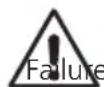
Utility (BEFORE YOU D.G) to harmful-puned wles or ge PLEASE NOTE: "Not" all I such that this (or any other utilities, such as gas lines, ever. This tool should "not avoid potentially harmfIMPORTANT NOTE: It is always recommended to contact your local to verify the location of any potentially lines.
nes will transmit an appropriate signal) line tracer can detect them, and other have "no" electrical charge what so "take the place of standard safety
protocol. Always contact your local utility before you dig to an or fatal mistakes!
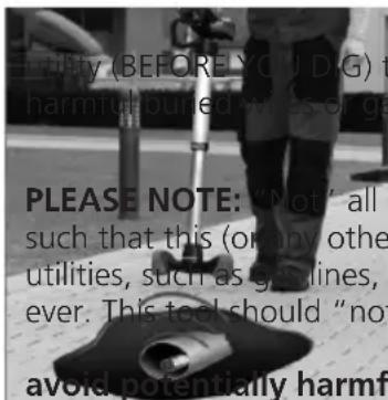
3.2 Standard Equipment
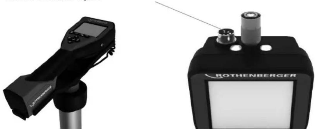
The ROLOC PLUS (No. 1500000057) comes with the following items (Figure 1):
- Module ROLOC PLUS (ROSCOPE 1000/i2000 sold seperatey)
- Manual
- Blow Mold Case
natural_image
Three black-and-white product photos: a handheld device, a vertical pole-mounted device, and a open case with tools (no visible text or symbols)Figure 1 – ROLOC PLUS (No. 1500000057) System Components
3.3 Installing ROSCOPE 1000/i2000 Imager / Module ROLOC PLUS
Only one device should be connected to the unit at a time. Always make sure the unit is off when installing or removing imagers or other accessories.
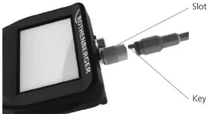
To use the ROSCOPE 1000/i2000 inspection device, the 17mm imager or the Module ROLOC PLUS must be connected to the handheld device. To secure connector to the handheld device, make sure the key and slot (Figure 2 and 3) are properly aligned. Once they are aligned, hand-tighten the knurled nut to hold the connection in place.
text_image
BOTHENBERGER Slot KeyFigure 2 - Cable Connections (Connector Style A, Black Color)
NOTE: Connector is the same for either ROSCOPE 1000/i2000 imager (or) Module ROLOC PLUS.
Slot for Connector Style B
natural_image
Two medical or industrial devices: a handheld device and a Rothenberger device, both without visible text or symbols.Figure 3 – Cable Connections (Connector Style B, Silver Color)
NOTE: Connector Style B is used to attach previous versions of the ROSCOPE Imager Cable.
1.8 m (4') cable extensions are available, for Connector A imager only, to increase the length of your cable up to 9 m (35') in length. To install an extension, first remove the imager cable from the handheld device by loosening the knurled nut. Connect the extension(s) to the handheld device as described above (Figure 2). The keyed end of the imager connects to the slotted end of the extension.
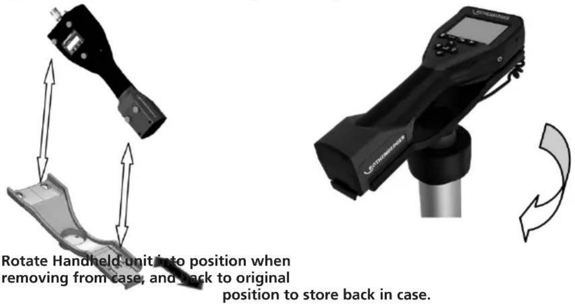
3.4 To Install Module ROLOC PLUS
Figure 4 shows the procedure for installing the ROSCOPE 1000/i2000 handheld unit to the mounting cradle on the Module ROLOC PLUS (line detector).
text_image
Rotate Handheld unit into position when removing from case, and back to original position to store back in case.Figure 4 – Installing ROSCOPE 1000/i2000 handheld unit to the mounting cradle
3.5 Tool Inspection
- Keep connectors clean.
- Inspect Battery for signs of wear or damage.
- Inspect Battery Charger for signs of wear or damage.
- Clean any foreign contaminants (grease, dirt, oil or sewage) from the device. Imager glass must be free of any debris to ensure optimal performance.
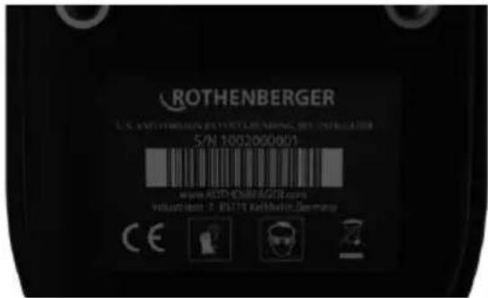
- Be aware of all warnings on label as shown in Figure 5.
text_image
ROTHENBERGER S.N. 1002/B00801 www.ROTHENBERGER.com Volustkelt: 2. RS178 Kathminder, GermanyFigure 5 – Warning Label
3.6 Tool and Work Area Set-Up
- Check work area for proper lighting,
- Flammable liquids, vapors or dust are not present in the work area.
4. Operating Instructions
- Read the entire manual.
• Charge battery and install. - Battery should be removed during storage to promote battery life.
5. Navigation Buttons
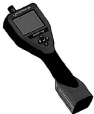
natural_image
Black handheld electronic device with a screen and control buttons (no visible text or symbols)
Measurement of depth
6. On-Screen Icons / Settings and Navigation
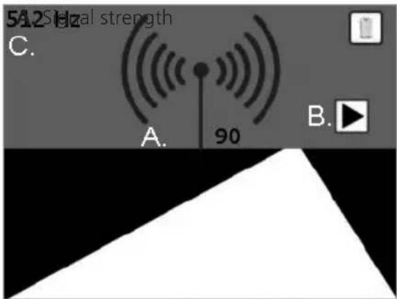
6.1 Locating Screen Display
ON SCREEN ICONS

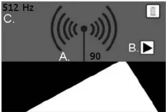
text_image
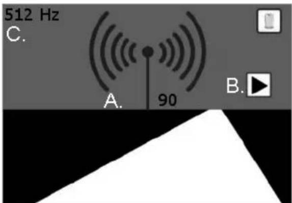
512 Hz C. A. 90 B.Figure 6 – Screen display in detection mode
A. Signal strength (numbers and emitter waves)
B. Indicator arrows
C. Probe frequency

No information available:
User may encounter this reading if emitter/SONDE is below or beyond range of locator (0,6 - 1,8m).
6.2 Tools / Menu
To change settings you need to tap the touch screen – a tools icon will appear in the lower left corner of the screen. Tap the tools icon and the following screen will open up.
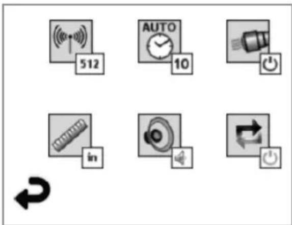
text_image
512 AUTO 10 inFigure 7 – Tools menu
Tap the following icons to adjust the settings as indicated below.

Frequency (512 Hz, 640 Hz, 50/60 Hz passave, 33 KHz active/passive)

Auto shut-off (10 min / 20 min / 30 min / never)

Headlights (no / off)

Unit of measure (English / Metric)

Volume (off / half / on)

Depth (single measurement / average - multi measurement)

Return to horizontal display (below)
7. On Screen Navigation
NOTE: The following screen navigations will ONLY occur when the inspection device is powered up.
When the ROSCOPE 1000/i2000 inspection device is powered on, the first screen that is displayed is referred to as the splash screen (Figure 8). This screen tells you the device is booting up. Once the product is fully powered up, the screen will automatically switch to the live screen.

text_image
ROTHENBERGER Vers. 4.11Figure 8 - Splash Screen
8. Live Screen - Line Detection (ROSCOPE 1000/i2000 w/ ROLOC PLUS)
Simply follow the indicator arrows (left / right) and walk in the direction of the path leading to the horizon, as though you were walking on the path itself. Watch as the signal strength increases by both the numeric indicator, as well as the antenna imitter waves. Also note the audible indicator as you get closer to the transmitter / SONDE (which also has a volume control).
text_image
5A2 Sialal strength C. A. 90 B.Figure 9 – Live Screen
B. Indicator arrows
C. SONDE Frequency
Once you have reached the strongest signal location, (forward/backward/left/right) press the button, and the screen will switch to the depth view, telling you the location of the transmitter/SONDE. Press the button again to return to the horizon view.
1. Horizontal View
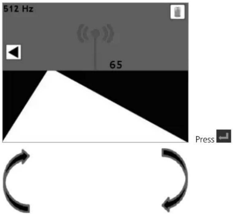
text_image
512 Hz 65 Press ←2. Vertical View
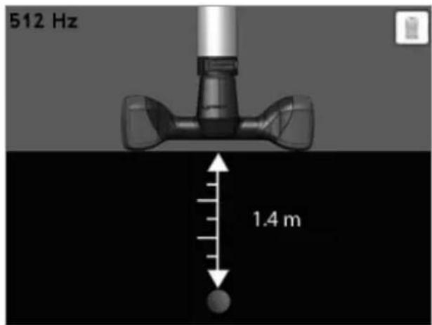
text_image
512 Hz 1.4 mPress ← to get back to 1.
Figure 10 – Signal/Depth Locator
9. Cleaning Instruction
- Remove battery from unit.
- Alcohol wipes, mild detergent and water to remove dirt and grease from the product.
- Recommend soft optical cloth for cleaning the LCD window.
- Recommend cotton cloth for cleaning imager head.
- Allow appropriate drying time before re-inserting the battery and operating.
10. Storage
- Unit should be cleaned prior to long term storage
- Store in a cool dry location
- Battery should be removed during storage to promote battery life.
11. Troubleshooting
| Symptom Possible Reason | Solution | |
| Display unit does not turn on | Battery is discharged Recharge battery | |
| Verify battery is in the battery compartment | Place battery in the battery compartment | |
| Faulty electronics Contact ROTHEN | BERGER Service Center | |
| Display turns on, but does not show image. | Loose cable connection Check cable connections. | |
| Imager head covered by debris Clean imager head | ||
| Display shows an unresponsive image | Image processor encountered an error | Turn OFF unit/turn ON to reset processor |
| Battery does not hold a charge | Battery may have discharged slightly during storage | Remove battery when storing |
| Run time dependent on LED usage | Recharge battery more often when extensive use of LEDs | |
| Battery may be damaged Replace battery | ||
| Life cycles of battery expired Replace battery | ||
| No Signal Wrong frequency | Verify frequency of your | sonde and adapt ROLOC frequency via menu |
Depth measurement shows:  | ROLOC PLUS is out of range | Verify strongest signal |
| ROSCOPE 1000/i2000 Error Code 1 "unplugged" | Error present when imager has been plugged in and working, and then has been removed | Contact Service Department |
| ROSCOPE 1000/i2000 Error Code 2 "Digital / No Video Sync" | Indicates that a digital imager has been identified but no video sync are present. | Contact Service Department |
| ROSCOPE 1000/i2000 Error Code 3 "Analog / No Video Sync" | Indicates that an analog imager has been identified but no video syns are present. | Contact Service Department |
| ROSCOPE 1000/i2000 Error Code 4 (PPI) "Video Data Not in Correct Format" | Indicate that the video data is not in the correct format. | Contact Service Department |
| ROSCOPE 1000/i2000 Error Code 5 "Aurora Detected" | This is a condition where the imagers automatic correction scheme (digital imager only) results in an image with video artifacts - the imager is then reset. If this condition persists after subsequent retries, this error is then presented. | Contact Service Department |
| ROSCOPE 1000/i2000Error Code 6“Tied or Dead Data Lines” | This is a self diagnostic error where the system configures itself to generate a test pattern that pattern is then validated. If the pattern is not correct, it indicates that there is a short circuit or open on the data lines from the video source(s) to the main processor. | Contact Service Department |
12. Accessories
| Accessory Name ROTHENBERGER Part Number | |
| ROSCOPE i2000 No. 1500000696 | |
| Replacement Module TEC No. 69601 | |
| Hook Magnet and Mirror No. 69615 | |
| Charger No. 1500000715 | |
| Module 25/16 (16 m Imager Reel) No. 1500000052 |
13. Disposal
Components of the unit are of recyclable material and should be put to recycling. For this purpose registered and certified recycling companies are available. For an environmental friendly disposal of the non-recyclable parts (e.g. electronic waste) please contact your local waste disposal authority or contact your local ROTHENBERGER authorized service center.
For EU countries only:
Do not dispose of electric tools with domestic waste. In accordance with European Directive 2012/19/EC on waste electrical and electronic equipment and its implementation as national law, electric tools that are no longer serviceable must be collected separately and utilised for environmentally compatible recycling.
14. Customer service
The ROTHENBERGER service locations are available to help you (see listing in catalog or on-line) and replacement parts and service are also available through these same service locations.
Order your accessories and spare parts from your specialist retailer or using our after-sales hotline:
Phone: +49 (0) 61 95 / 800 - 0
Fax: +49 (0) 6195 / 800 - 3500
www.rothenberger.com
natural_image
Three black-and-white product photos: a handheld device with a screen, a vertical pole-mounted device, and an open case containing a tool kit (no visible text or symbols)natural_image
Two black medical or industrial devices, one with a display and the other labeled 'BOTHENBERGER' (no visible text beyond branding)text_image
ROTHENBERGER S/N 1002000001 www.ROTENBERGER.COM Industments: 7-5079 Rothem Germanynatural_image
Black handheld electronic device with a screen and control buttons (no visible text or symbols)
text_image
512 AUTO 10 inFrequency (512 Hz, 640 Hz, 50/60 Hz passive, 33 KHz active/passive)

text_image
51.2 Hz C. A. 90 B.natural_image
Three black-and-white product photos: a handheld device with LCD display, a vertical pole-mounted device, and an open case with tools (no visible text or symbols)Figura 1 - ROLOC PLUS (N.° 1500000057) Componentes del sistema
natural_image
Black handheld electronic device with a screen and control buttons (no visible text or symbols)
text_image
512 AUTO 10 intext_image
51.2 Hz C. A. 90 B.natural_image
Black handheld electronic device with a screen and antenna, mounted on a stand (no visible text or symbols)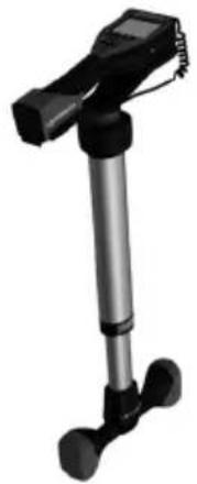
natural_image
Black and silver photo of a tripod-mounted device with adjustable legs and feet (no text or symbols visible)
natural_image
Open black mechanical tool kit with visible internal components and a label reading 'MANUAL' (no other text or symbols)Figura 1 - ROLOC PLUS (N. 1500000057) Componenti del sistema
natural_image
Two black medical or industrial devices, one with a display and the other labeled 'ROTHENBERGER' (no visible text beyond branding)natural_image
3D rendered image of a handheld electronic device with a screen and control buttons (no visible text or symbols)
text_image
512 AUTO 10 intext_image
ROTHENBERGER Vers. 411natural_image
Black handheld electronic device with a screen and cylindrical base (no visible text or symbols)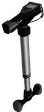
natural_image
Black handheld device with vertical and horizontal legs, no visible text or symbols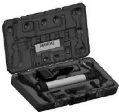
natural_image
Open mechanical tool kit with labeled 'MANUAL' (no other text or symbols visible)natural_image
Two black electronic devices, one with a display and the other labeled 'ROTHENBERGER' (no visible text or symbols on device body)natural_image
Black handheld electronic device with a screen and control buttons (no visible text or symbols)
Dieptemeting
6. On-Screen pictogrammen / instellingen en navigatie
6.1 Positionering scherm
OP SCHERMPICTOGRAMMEN
text_image
512 Hz C. A. 90 B.text_image
512 AUTO 10 inKoplampen (on / off)

Volume (off / half / on)

text_image
ROTHENBERGER Vers. 4.11Figuur 8 – Splash-scherm
8. Rechtstreeks scherm – Leidingzoeker (ROSCOPE 1000/i2000 w/ ROLOC PLUS)
text_image
51.2 Hz C. A. 90 B.B. Indicatiepijlen
C. Sonde frequentie
Figuur 9 – Live-scherm
natural_image
Three black-and-white product photos: a handheld device, a vertical pole-mounted device, and an open case with tools (no visible text or symbols)Figura 1 - ROLOC PLUS (N.° 1500000057) Componentes do sistema
3.3 Instalar o ROSCOPE 1000/i2000 imagens / Modul ROLOC PLUS

natural_image
Two black medical or industrial devices, one with a display and the other labeled 'ROTHENBERGER' (no visible text beyond branding)natural_image
Two technical illustrations of a device with directional arrows indicating movement or force (no text or symbols present)text_image
ROTHENBERGER S/N 1002000001 www.ROTHENBERGER.COM Industments: P 50779 RothenzerGermanyFigura 5 – Etiqueta de aviso
natural_image
Black handheld electronic device with a screen and control buttons (no visible text or symbols)
text_image
512 AUTO 10 inFigura 7 – Menu Ferramentas
text_image
ROTHENBERGER Vers. 4.11Frekvenser ....512 Hz, 640 Hz, 50/60 Hz passive, 33 KHz active/passive
Skønnet batterilevetid ......3-5 timer
(Se batterispecifikation ovenfor for ROSCOPE 1000/i2000)
natural_image
Exterior view of a black handheld electronic device with a screen and cylindrical base (no visible text or symbols)
natural_image
Black and white photo of a handheld device with a vertical shaft and two feet (no visible text or symbols)
natural_image
Open mechanical tool kit with labeled parts, no visible text or symbols on the main bodyFigure 1 - ROLOC PLUS (Nr. 1500000057) Systemkomponenter
3.3 Montering af ROSCOPE 1000/i2000 Imager / modul ROLOC PLUS

natural_image
Two ROTHENBERGER medical devices, one displaying a handheld device and the other a black device with a cylindrical component (no visible text or symbols)natural_image
Black handheld electronic device with a screen and control buttons (no visible text or symbols)
Dybdemåling
text_image
512 AUTO 10 intext_image
ROTHENBERGER Vers. 4.11text_image
51.2 Hz C. A. 90 B.B. Indikatorpile
C. Sondefrekvens
natural_image
Three black-and-white product photos: a handheld device with LCD screen, a vertical pole-mounted device, and a open case containing a tool kit (no visible text or symbols)Figur 1 - ROLOC PLUS (Nr. 1500000057) Systemkomponenter
3.3 Montering ROSCOPE 1000/i2000 (eller) Modul ROLOC PLUS

natural_image
Two medical or industrial devices: a handheld device and a Rothenberger device, both without visible text or symbols.Figur 3- Kabelanslutningar (Anslutning modell B, silver)
Figur 4 - Installing ROSCOPE 1000/i2000 handheld unit to the mounting cradle
natural_image
Black handheld electronic device with a screen and control buttons (no visible text or symbols)
Djupmätning
text_image
512 AUTO 10 inFigur 7 – Verktygsmenyn
text_image
ROTHENBERGER Vers. 4.11Figur 8 – Splash-skärambild
8. Live skärm – Rördetektering (ROSCOPE 1000/i2000 w/ ROLOC PLUS)
natural_image
Three black-and-white product photos: a handheld device, a vertical pole-mounted device, and an open case with tools (no visible text or symbols)Figur 1 – ROLOC PLUS (Nr. 1500000057) Systemkomponenter
natural_image
Two black medical or industrial devices, one with a display and the other a labeled ROTHENBERGER device (no visible text or symbols on the devices themselves)natural_image
Black handheld electronic device with a screen and control buttons (no visible text or symbols)
Dybdemåling
text_image
512 AUTO 10 inFigur 7 – Tools-meny
text_image
ROTHENBERGER Vers. 4.11Figur 8 – Startskjerm
natural_image
Exterior view of a black handheld electronic device with a screen and stand (no visible text or symbols)
natural_image
Black and white photo of a handheld device with a vertical shaft and two feet legs (no visible text or symbols)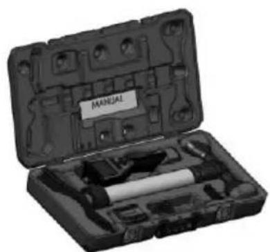
natural_image
Open mechanical tool kit with labeled 'MANUAL' (no other text or symbols visible)natural_image
Black handheld electronic device with a screen and metallic base (no visible text or symbols)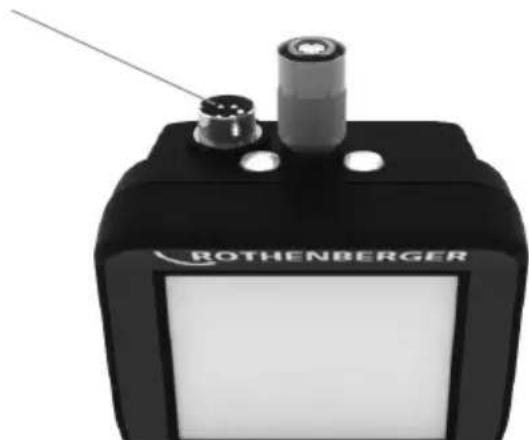
natural_image
Close-up of a black Rothenberger electronic device with two ports and a central lens (no visible text or symbols on body)natural_image
Black handheld electronic device with a screen and control buttons (no visible text or symbols)
Syvyyden mittaus
text_image
512 AUTO 10 innatural_image
Three black-and-white product photos: a handheld device with a screen, a vertical stand, and a compact case with a labeled box (no visible text or symbols)natural_image
Two medical or industrial devices: a handheld device and a Rothenberger device, both without visible text or symbols.natural_image
Black handheld electronic device with a screen and control buttons (no visible text or symbols)
Pomiar głębokości
text_image
512 AUTO 10 innatural_image
Person using a portable pusher on a paved surface with a circular device underneath (no visible text or symbols)natural_image
Black handheld electronic device with a screen and antenna, mounted on a cylindrical stand (no visible text or symbols)
natural_image
Black and silver photo of a handheld device with a vertical rod and two feet (no visible text or symbols)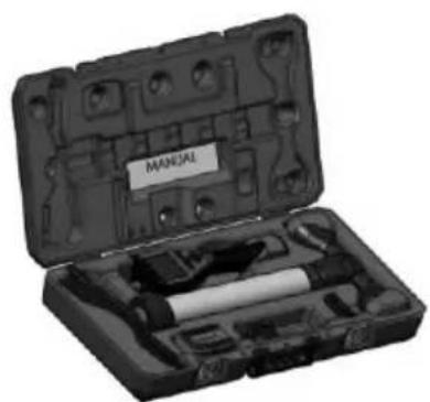
natural_image
Open mechanical tool kit with labeled parts, no visible text or symbols on the main bodynatural_image
Black JOTUS WHEELER device with digital display and control buttons (no visible text or symbols on body)
natural_image
Exterior view of a black Rothenberger electronic device with two ports and a probe (no visible text or symbols on body)natural_image
Black handheld electronic device with a screen and control buttons (no visible text or symbols)
Měření hloubky
text_image
512 AUTO 10 intext_image
ROTHENBERGER Vers. 4.11natural_image
Black and silver photo of a handheld device with a vertical rod and two feet (no visible text or symbols)
natural_image
Open mechanical tool kit with labeled parts, no visible text or symbols on the main body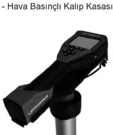
text_image
RÖTHENBERGER Çalı Fişnatural_image
Two medical or industrial devices: a handheld device and a Rothenberger device, both without visible text or symbols.natural_image
Black handheld electronic device with a screen and control buttons (no visible text or symbols)
Derinlik ölçümü
text_image
ROTHENBERGER Vers. 4.11natural_image
Three black-and-white product photos: a handheld device with LCD display, a vertical pole-mounted device, and a open case containing a tool kit (no visible text or symbols)natural_image
Black handheld electronic device with a screen and control buttons (no visible text or symbols)
Mélységmérés
text_image
512 AUTO 10 intext_image
ROTHENBERGER Vers. 4.11natural_image
Three black-and-white product photos: a handheld device, a vertical pole-mounted device, and a open case with a tool (no visible text or symbols)natural_image
Two black medical or industrial devices, one with a display and the other labeled 'ROTHENBERGER' (no visible text beyond branding)natural_image
Black handheld electronic device with a screen and control buttons (no visible text or symbols)
Μέτρηση βάθους
text_image
512 AUTO 10 innatural_image
Two curved arrows forming a loop, no text or symbols presentnatural_image
Three black-and-white product photos: a handheld device, a vertical pole-mounted device, and an open case with tools (no visible text or symbols)natural_image
Two ROTHENBERGER medical devices, one displaying a digital display and the other a black device with a cylindrical tip (no visible text or symbols)text_image
ROTHENBERGER S.N. AND HORIZON BALANCE PENSIBLE BLOOD COLOR S.N. 1002000001 www.ROTHENBERGER.COM Házhuang: 7-2017P AgGolding Germanynatural_image
Black handheld electronic device with a screen and control buttons (no visible text or symbols)
Измерение глубины
text_image
ROTHENBERGER Vers. 4.11natural_image
Three black-and-white product photos: a handheld device with LCD display, a vertical support post, and an open case with tools (no visible text or symbols)natural_image
Two black medical or scientific devices, one displaying a display and the other a labeled ROTHENBERGER device with a cylindrical component (no visible text or symbols on the devices themselves)natural_image
Black handheld electronic device with a screen and control buttons (no visible text or symbols)
深さ測定
6. 画面の記号/設定とナビゲーション
6.1 位置測定画面の表示
スクリーンアイコンについて
text_image
512 Hz C. A. 90 B.図6-検知モードの画面表示
A. 信号強度(数字とエミッタ波)
B. 表示器の矢印
C. 可聽周波数

情報なし:
text_image
ROTHENBERGER Vers. 4.11図8-スプラッシュスクリーン
natural_image
Blank grid paper with uniform gray squares on white background (no text or symbols)NOteS
ROTHENBERGER Worldwide
| Australia | ROTHENBERGER Australia Pty. Ltd.Unit 6 • 13 Hoyle Avenue • Castle Hill • N.S.W. 2154Tel + 61 2 / 98 99 75 77 • Fax + 61 2 / 98 99 76 77rothenberger@rothenberger.com.auwww.rothenberger.com.au | Italy | ROTHENBERGER Italiana s.r.l.Via G. Reis Romoli 17-19 • L-20019 Settimo MilaneseTel + 39 002/33 50 6001 • Fax + 39 002/33 50 0151info@rothenberger.it • www.rothenberger.it |
| Austria | ROTHENBERGER Werkzeuge- und Maschinen Handelsgesellschaft m.b.H.Gewerbeparkstraße 9 • A-5081 AnifTel + 43 62 46 / 7 20 91-45 • Fax + 43 62 46 / 7 20 91-15office@rothenberger.at • www.rothenberger.at | Netherlands | ROTHENBERGER Nederland by Postbus 45 • NL-5120 AA RijenTel + 31 11 61/729 35 79 • Fax + 31 11 61/729 39 08info@rothenberger.nl • www.rothenberger.nl |
| Belgium | ROTHENBERGER Benelux bvbaAntwerpsesteenweg 59 • B-2630 AartelaarTel + 32 3 / 8 77 22 77 • Fax + 32 3 / 8 77 08 94info@rothenberger.be • www.rothenberger.de | Poland | ROTHENBERGER Polska Sp.z.o.o.Ul. Annopol 4A • Budynek C • PL-03-236 WarszawaTel + 48 22/2 / 13 59 000 • Fax + 48 22/2 / 2 13 59 01biuro@rothenberger.pl • www.rothenberger.pl |
| Brazil | ROTHENBERGER do Brasil LTDAAv. Fagundes de Oliveira, 538 • Galpão A409950-300 • Diadema / SP • BrazilTel + 55 11 / 40 44- 4248 • Fax + 55 11 / 40 44- 5051spacente@rothenberger.com.br • www.rothenberger.com.br | Russia | ROTHENBERGER Russia Avlosavodskaya str. 25115280 Moscow, RussiaTel + 7 495 / 792 59 444 • Fax + 7 495 / 792 59 46info@rothenberger.ru • www.rothenberger.ru |
| Bulgaria | ROTHENBERGER Bulgaria GmbHBoul. Sitnjakovo 79 • BG-1111 SofiaTel + 35 9 / 2 9 46 14 59 • Fax + 35 9 / 2 9 46 12 05info@rothenberger.bbg • www.rothenberger.dbg | South Africa | ROTHENBERGER-TOOLS SA (PTY) Ltd.P.O. Box 49360 • Edtenvale 16310165 Vandertbil Street, Meadowdale Germiston Gauteng (Johannesburg), South AfricaTel + 27 111/3 72 96 311 • Fax + 27 111/3 72 96 332info@rothenberger.co.za • www.rothenberger.co.za |
| China | ROTHENBERGER Pipe Tooll (Shanghai) Co., Ltd.D-4, No.195 Qianpu Road, East New Area of Songjiang Industrial Zone, Shanghai 201611, ChinaTel + 86 21 / 67 60 20 61 • + 86 21 / 67 60 20 67Fax + 86 21 / 67 60 20 63 • office@rothenberger.cn | Spain | ROTHENBERGER S.A.Ctra. Durango-Borrio, Km 2 • E-48220 Abadiano (Vizcaya)(P.O. Box) 1117 • E-48200 Durango (Vizcaya)Tel + 34 94/6 21 01 000 • Fax + 34 94/6 21 01 311export@rothenberger.es • www.rothenberger.es |
| Czech Republic | ROTHENBERGER CZPrumyslova 1306/7 • 102 00 Praha 10Tel +420 271 730 183 • Fax +420 267 310 187prodej@rothenberger.cz • www.rothenberger.cz | Sweden | ROTHENBERGER Sweden ABHernvämsgatan 22 • S- 171 54 Solna, SverigeTel + 46 8/54 60 23 00 • Fax + 46 8/54 60 23 01rosve@rothenberger.se • www.rothenberger.se |
| Denmark | ROTHENBERGER Scandinavia A/SSmedevænget 8 • DK-9560 HadsundTel + 45 98/115 75 66 • Fax + 45 98/115 68 23roscan@rothenberger.dk | Switzerland | ROTHENBERGER (Schweiz) AGHerostr. 9 • CHI-8048 ZürichTel + 411 44/435 30 30 • Fax + 41 44/435 30 30• info@rothenberger-werkzeuge.ch |
| France | ROTHENBERGER France S.A.24, rue des Drapiers, BP 45033 • F-57071 Metz Cedex 3Tel + 33 3 / 87 74 92 92 • Fax + 33 3 / 87 74 94 08info-fr@rothenberger.com • www.rothenberger.fr | Turkey | ROTHENBERGER TÜRKIYEROTHENBERGER Center, Barbamos Bulkami No29TR-34775 erifali / Umraniye-IstanbulTel + 90/216 449 24 85 • Fax + 90/216 449 24 87rothenberger@rothenberger.com.trwww.rothenberger.com.tr |
| Germany | ROTHENBERGER Deutschland GmbHIndustriestraße 7 • D-65779 Kelkheim/GermanyTel + 49 61 95 / 800 81 00 • Fax + 49 61 95 / 800 37 39verkauf-deutschland@rothenberger.comwww.rothenberger.com | UAE | ROTHENBERGER Middle East FZCOPo Box 261190 • Jebel Ali Free ZoneDubai, United Arab EmiratesTel + 97/11/48 83 97/77 • Fax + 97/11/48 83 97 57office@rothenberger.aee |
| Greece | ROTHENBERGER Werkzeuge Produktion GmbHLilenthalstraße 71- 87 • D-37235 Hessisch-LichtenauTel + 49 56 02 / 93 94-0 • Fax + 49 56 02 / 93 94 36 | UK | ROTHENBERGER EQUIPMENT TRADING & SERVICES LLCPo Box 91208 • Mussafah Industrial Area Abu Dhabi, United Arab EmiratesTel + 97/11/25 50 011 54 • + 97/11/25 50 011 53uaesales@rothenberger.ae |
| Hungary | ROTHENBERGER Hungary Kft.Gubaciut 26 • H-1097 BudapestTel + 36 1 / 3 47- 50 40 • Fax + 36 1 / 3 47 - 50 59info@rothenberger.hu • www.rothenberger.hu | USA | ROTHENBERGER USA LLC7130 Clinton Road • Loves Park, IL 61111, USATel +11/80 05 45 76 98 • Fax + 11/81 56 33 08 79pipetools@rothenberger-usa.comwww.rothenberger-usa.com |
| India | ROTHENBERGER India Pvt. Ltd.Plot No 17, Sector - 37, Pace city-I Gurgaon, Haryana - 122 001, IndiaTel 1124- 4618900 • Fax1124- 4019471contactus@rothenbergerindia.comwww.rothenberger.com | ROTHENBERGER Werkzeuge GmbHIndustriestraße 7D-65779 Kellshheim / Germany |