
R550 - Uncategorized ROTHENBERGER - Free user manual and instructions
Find the device manual for free R550 ROTHENBERGER in PDF.

| Product Type | Drain cleaning machine (electric drain cleaner) |
| Brand | Rothenberger |
| Model | R550 |
| Supply voltage | 230-240 V, 50 Hz (also available in 110-115 V, 50-60 Hz) |
| Power consumption | 440 W |
| Rotation speed | 575 min⁻¹ |
| Weight | Approx. 15 kg |
| Spiral diameter (standard) | Ø 16 mm |
| Spiral diameter (accessories) | Ø 8 mm / 10 mm |
| Maximum working length | 40 m |
| Recommended pipe diameter | 20 to 100 mm |
| Sound pressure level | 86 dB(A) (K_WA = 3 dB) |
| Total vibration value | < 2.5 m/s² (K = 1.5 m/s²) |
| Electrical safety device | Integrated PRCD switch (10-30 mA differential) |
| Direction of rotation | Right (clearing) / Left (spiral release) |
| Control | Progressive control lever |
| Required personal protective equipment | Guide gloves (riveted), disposable latex gloves, rubber boots, helmet, safety shoes, safety vest |
| Routine maintenance | Lubrication of grease points (daily and every 100 h); cleaning with ROWONAL product |
| Spare parts available | Clamping jaws, spirals, tools, guide gloves, guide hoses, etc. |
| Customer service | ROTHENBERGER Service: +49 (0) 61 95 / 800 - 8200 |
| Disposal | Do not dispose of with household waste; recycle in accordance with WEEE directive 2012/19/EU |
Frequently Asked Questions - R550 ROTHENBERGER
User questions about R550 ROTHENBERGER
0 question about this device. Answer the ones you know or ask your own.
Ask a new question about this device
Download the instructions for your Uncategorized in PDF format for free! Find your manual R550 - ROTHENBERGER and take your electronic device back in hand. On this page are published all the documents necessary for the use of your device. R550 by ROTHENBERGER.
USER MANUAL R550 ROTHENBERGER
natural_image
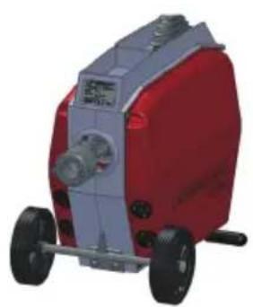
Exterior view of a Rothenberger industrial machine with handle and wrench (no text or symbols on body)EN Instructions for use
Overview
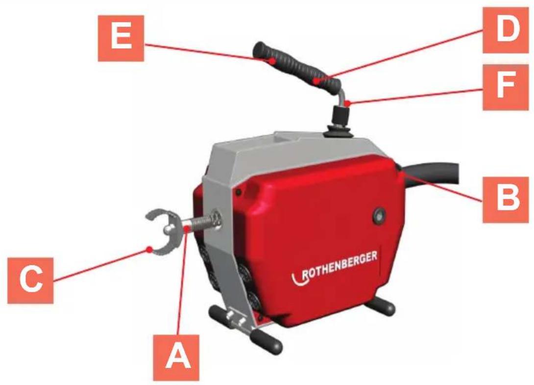
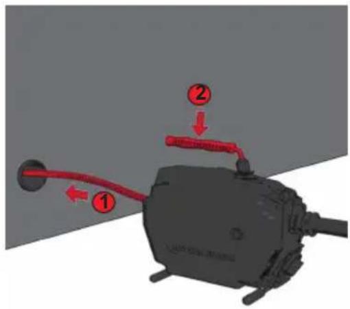
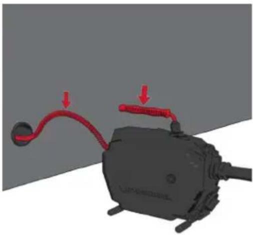
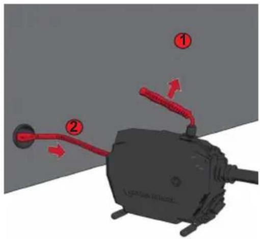
A Use standard spirals
1
natural_image
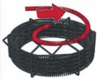
Black wire coil wrapped around a red spiral arrow, no text or symbols present2
natural_image
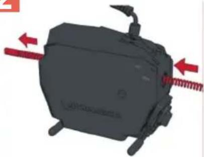
3D rendering of a mechanical device with red directional arrows indicating movement or force (no text or symbols)3
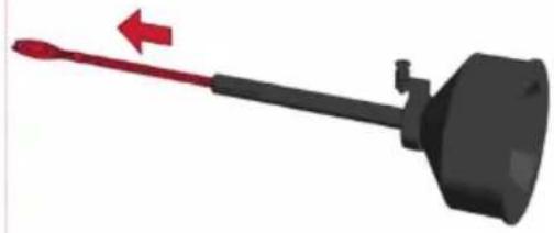
B Fit 8 mm / 10 mm spirals
1
natural_image
3D illustration of a black tool with a red arrow pointing to the tip, no text or symbols present2
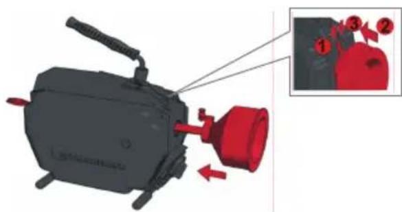
natural_image
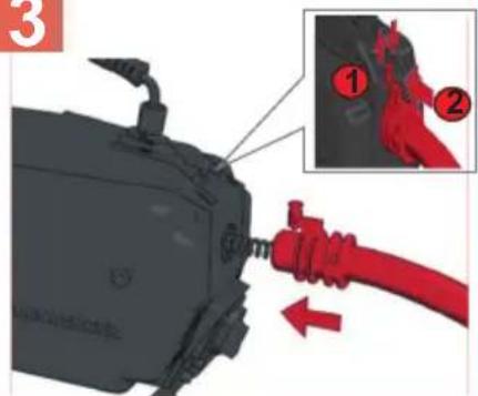
3D illustration of a mechanical device with red components and an inset showing three numbered parts (1, 2, 3) — no text or symbols present.C Fit tools D
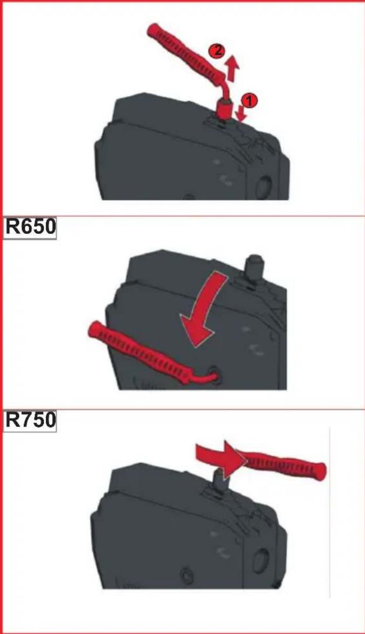
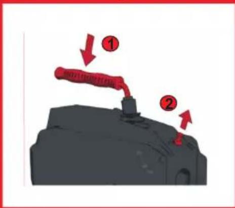
To adjust the handle
E Carry Position
natural_image
3D rendered mechanical component with a red arrow pointing to a top part (no text or symbols visible)F
Start / Stop
ART ->
G Operating
1
2
3
natural_image
3D diagram of a mechanical component with red arrows indicating motion or force direction (no text or symbols)4
H Care and maintenance
natural_image
Close-up of a mechanical component with a red arrow and label (no readable text or symbols)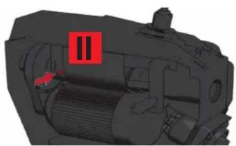
natural_image
3D mechanical assembly diagram showing internal components with no visible text or symbolsReplace the clamp jaws R550/R650 I
1
natural_image
3D rendered mechanical component with red housing and arrow symbol, no readable text or labels2
natural_image
Mechanical assembly diagram showing two numbered components with red arrows indicating directional movement (no text or symbols present)3
natural_image
Two-panel image showing a red arrow pointing to a mechanical component, no text or symbols present.4
natural_image
3D mechanical assembly diagram showing red directional arrows indicating flow or movement (no text or symbols)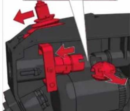
natural_image
3D mechanical assembly diagram showing red directional arrows indicating movement or force (no text or symbols)5
6
natural_image
Red and black 3D model of a mechanical device with heart-shaped buttons (no text or symbols visible)Replace the clamp jaws R750
K
1
natural_image
Red and gray industrial machine with wheels and control panel (no visible text or symbols)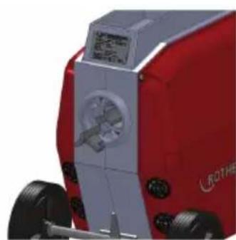
natural_image
Red and silver industrial machine with visible wheels and a mounted sensor or fan (no text or symbols)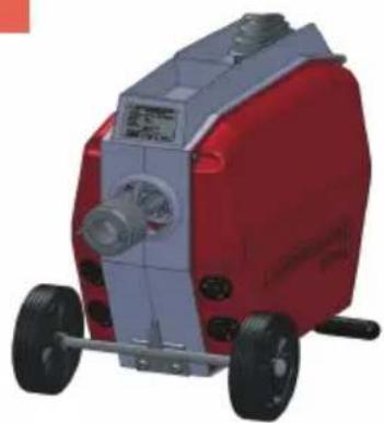
natural_image
Red and silver industrial machine with wheels and control panel (no visible text or symbols)Intro
EU-DECLARATION OF CONFORMITY
We declare on our sole accountability that this product conforms to the standards and guidelines stated.
DECLARATION EU DE CONFORMITÉ
Herstellerunterschrift Manufacturer/ authorized representative signature
ppa. Thorsten Bühl
Director Corporate
Technology Approval & Patents
D-65779 Kelkheim/Germany
Intro
| DEUTSCH - Originalbetriebsanleitung!Bedienungsanleitung bitte lesen und aufbewahren! Nicht wegwerfen! Bei Schäden durch Bedienungsfehler erlischt die Garantie! Technische Änderungen vorbehalten! | Seite 2 |
| ENGLISHPlease read and retain these directions for use. Do not throw them away! The warranty does not cover damage caused by incorrect use of the equipment! Subject to technical modifications! | page 12 |
| FRANÇAISLire attentivement le mode d'emploi et le ranger à un endroit sûr! Ne pas le jeter! La garantie est annulée lors de dommages dûs à une manipulation erronée! Sous réserve de modifications techni | page 21 |
| ESPANOL¡Por favor, lea y conserve el manual de instrucciones! ¡No lo tire! ¡En caso de daños por errores de manejo. la garantía queda sin validez! Modificaciones técnicas reservadas! | página 31 |
| ITALIANOPer favore leggere e conservare le istruzioni per l'uso! Non gettarle via! In caso di danni dovuti ad errori nell'uso. la garanzia si estingue! Ci si riservano modifiche tecniche! | Pagina 41 |
| NEDERLANDSLees de handleiding zorgvuldig door en bewaar haar goed! Niet weggooien! Bij schade door bedieningsfouten komt de garantieverlening te vervallen! Technische wijzigingen voorbehouden! | bladzijde 51 |
| PORTUGUESQueiram ler e guardar o manual de instruções! Não deitar fora! Em caso de avarias por utilização incorrecta. extingue-se a garantía! Reservado o direito de alteracões técnicas! | pagina 61 |
| DANSKLæs betjeningsvejledningen, og gem den til senere brug! Smid den ikke ud! Skader, som måtte opstå som følge af betieningsfeil. medfører, at garantien mister sin αvldighRet til tekniske ændringeforbeholdes | side 71 |
| SVENSKALås igenom bruksanvisningen och förvara den väl! Kasta inte bort den! Garantin upphör om apparaten har använts eller betjänats på ett felaktigt sätt! Med reservation för tekniska ändringar! | sida 80 |
| NORSKLes bruksanvisningen og oppbevar den vell! Ikke kast den! Oppstår skader på grunn av betjeningsfeil opphører garantiens αvldighet! Tekniske forandringer forbeholdes! | side 89 |
| SUOMILue ja säilytä tämä käyttöohje! Älä heitä pois! Takuu ei kata käyttövirheistä aiheutuvia vahinkoja! Oikeudet teknisiin muutoksiin pidätetään! | sivulta 98 |
| POLSKIInstrukcjë obsługi prosze przeczytac i przechowac! Nie wyrzucac! Przy uszkodzeniach wynikajacych z blédów obsługi wygasa gwarancja! Zmiany techniczne zastrzezone! | strony 107 |
| CESKYNavod k obsluze si prosim přečtěte a uschovejte jej! Nevyhazujte jej! V pripade poškozeni zpusobenem chybnou obsluhou zanika zaruka! Technicke změny isou vyhrazeny! | Stránky 117 |
| TURKÇEKullanim açıklamalarini lütfen dikkatlice okuyunuz ve bir yerde muhafaza ediniz! Çöpe atmayiniz! Kullaniminda yapılan hatalar, garantinin silinmesine neden olur! Teknik deðipiklikler yapma hakkimiz saklidir! | sayfa 126 |
| MAGYARKérjük, olvassa el és őrizze meg a kezelési utasítást! Ne dobja el! A helytelen kezelésből származó károsodások esetén megszůnik a jótállás! Můszaki változtatások fenntartva! | oldaltól 1 35 |
| БЪЛГАРСКИПрочетете внимателно и запазете инструкцията за експлоатация! Не я захвърляйте или унищожавайте! При настъпили дефекти вследствие на неправилно обслужване гаранцията отпада! Технически изменения по уреда са изключително в компетенцията на фирмата производител! | Страница 144 |
| ESTUPalun lugege kasutusjuhend läbi ja hoidke alles! Ärge visake ära! Kä-sitsemisvigadest tingitud kahjustuste korral kaotab garantii kehtivuse! Õigus tehnilisteks muudatusteks reserveeritud! | Lehekülg 154 |
| LIETUVOSPerskaitykite naudojimo instrukciją ir pasilikite ją! Neišmeskite! Garan-tija nebus taikoma gedimams, atsiradusiems dėl netinkamo naudojimo! Pasiliekama teisė daryti techninius pakeitimus! | Pusla-pis 163 |
| LATVIESULüdzu, izlasiet un uzglabājiet lietošanas instrukciju! Nemest prom! Ja ir bojājumi ekspluatācijas klūdas dēl, garantija zaudē spēku! Paturēt tehniskas izmaiņas! | Lappuse 172 |
| ΕΛΛΗΝΙΚΑΟδηγίες χειρισμού παρακαλείσθε να τις διαβάσετε και να τις φυλάσσετε! Μην τις πετάξετε! Σε ζημιες από σφάλματα χειρισμού παυει να ισχύει η εγγύηση! Με επιφύλαξη για τεχνικές αλλαγές! | Σελίδα 181 |
| ΡΥССКИИПрочтите инструкцию по эксплуатации и сохраняйте её для дальнейшего использования! В случае поломки инструмента из-за несоблюдения инструкции клиент теряет право на обслуживание по гарантии! Возможны технические изменения! | Страница 191 |
| 中文版请阅读并妥善保存本使用说明书!请勿丢弃!不正当使用所造成的损害不属于保证范围!保留因技术变化而对文档内容进行修改的权利! | 第 201 页 |
R550: 40-100mm, R600-650: 20-150mm, R750: 50-200mm
Email: service@rothenberger.com
www.rothenberger.com
10 Entsorgung
1.1 General safety instructions....13
1.2 Special safety instructions....14
1.3 Residual risks.... 15
1.4 Intended use 15
2 Technical Data / Applications 15
3 Scope of delivery....16
4 Power connection....16
4.1 Putting the PRCD switch into operation 16
5 Function of the Unit....16
5.1 Use standard spirals (A)....16
5.2 Fit 8 mm / 10 mm spirals (B)....17
5.3 Fit tools (C) 17
5.4 To adjust handle (D)....17
5.5 Carry position (E) 17
5.6 Safety gloves....18
5.7 Start / Stop (F)....18
5.8 Operation (G) 18
6 Care and Maintenance....19
7 Replace the calmp jaws....19
7.1 R550 - R650 (I) 19
7.2 R750 (K)....19
8 Accessories....20
9 Customer service 20
10 Disposal 20
Markings in this document:

Danger!
This sign warns against the danger of personal injuries.
Caution!

This sign warns against the danger of property damage and damage to the environment.

Call for action
1.1 General safety instructions

ATTENTION! When using electric tools, the following fundamental safety measures must be taken to prevent electric shock, injury or fire.
Read all of these instructions before you use the electric tool, and store the safety instructions properly.
Service and maintenance:
1 Regular cleaning, maintenance and lubrication. Always pull the electrical plug before any adjustment, maintenance or repair.
2 Have your device repaired only by qualified experts and only with original replacement parts. This ensures the continued safety of the device.
Working safely:
1 Keep your work area orderly. A messy work area can cause accidents.
2 Consider environmental influences. Do not expose electric tools to rain. Do not use electric tools in damp or wet environments. Keep the work area well lit. Do not use electric tools where there is a risk of fire or explosion.
3 Protect yourself from electric shock. Avoid physical contact with earthed parts (such as pipes, radiators, electric stoves or cooling devices).
4 Keep other people away. Do not let other people — especially children — touch the electric tool or its cable. Keep them away from the work area.
5 Store electric tools safely when they are not in use. Unused electric tools should be kept in a dry, high or closed area, out of reach of children.
6 Do not overload your electric tool. Work is better and safer within the performance range indicated.
7 Use the right electric tool. Don't use low-performance machines for heavy-duty jobs. Do not use the electric tool for purposes for which it was not intended. For example, do not use a portable circular saw for cutting tree branches or logs.
8 Wear proper clothing. Do not wear loose clothing or jewellery, as they can get caught in moving parts. When working outdoors, wear slip-resistant shoes. Wear a hairnet over long hair.
9 Use protective gear. Wear safety glasses. Wear a breathing mask during work that creates dust.
10 Connect the dust extraction equipment. If there are connections to dust extraction and collection equipment, make sure that they are connected and properly used.
11 Do not use the cable for purposes for which it was not intended. Never use the cable to pull the plug from the socket. Protect the cable from heat, oil and sharp edges.
12 Secure the work piece. Use clamps or a vice to hold the work piece firmly. They will hold it more securely than your hand can.
13 Avoid abnormal postures. Make sure to stand securely and always keep your balance.
14 Maintain your tools with care. For better and safer work, keep cutting tools sharp and clean. Follow the instructions for lubrication and changing tools. Regularly inspect the electric tool's connection cable, and if it is damaged, have it replaced by an authorized expert. Regularly check extension cords and replace them if they are damaged. Keep the handles dry, clean and free of oil and grease.
15 Pull the plug from the socket. When not using the electric tool, before maintenance or when changing tools, such as saw blades, drills and cutting bits.
16 Do not leave any tool keys inserted. Before switching on, check to see that keys and adjustment tools have been removed.
17 Avoid unintentional activation. When plugging the tool in, make sure that the switch is turned off.
18 Use outdoor extension cords. When outdoors, use only extension cords that are approved and appropriately marked.
19 Be alert. Pay attention to what you do. Approach your work sensibly. Do not use the electric tool when you are distracted.
20 Check the electric tool for damage. Before using the electric tool, you must inspect safety equipment or slightly damaged parts carefully to ensure that they work properly and as intended. Check to see that the moving parts operate freely and don't stick, and to make sure no parts are damaged. All parts must be mounted properly and meet all the conditions for ensuring trouble-free operation of the electric tool.
Damaged safety equipment and parts must be properly repaired or replaced by a professional facility, unless otherwise indicated in the user manual. Damaged switches must be replaced by a customer service facility.
Never use an electric tool whose switch cannot be turned on and off.
21 Caution. Using other insertion tools and accessories may cause injury.
22 Have your tool repaired by an electrical expert. This electric tool meets applicable safety requirements. Repairs must be made only by an electrical expert using original replacement parts. Otherwise accidents many occur.
1.2 Special safety instructions
Use only the appropriate guide glove to guide the spiral (for example, rivet glove left 72120, right 72121). Do not continue to use a damaged rivet glove. (A rivet glove is not personal safety equipment according to 2016/425/EU - see also 6.6).
When using the rivet glove, make absolutely sure also to wear a disposable latex glove under the rivet glove for hygienic reasons. (Do not continue using a damaged latex glove.).
The spirals must be removed completely from the holding cage before machine is turned on.
Wear rubber boots (for insulation) when performing cleaning work.
Before inserting the plug into the electrical socket, make absolutely sure that the pipe cleaning machine is switched to 0 or OFF.
Whenever using electrical devices, always observe the specified voltage and generally work with a protective tube and safety gloves.
Choose the right tool for the clog and for the pipe diameter to be cleaned, in order to prevent the tool from hooking into the clog and the spiral from ejecting from the pipe.
To prevent damage, use this machine and its accessories only to clean waste water pipes — never chimneys, wells, etc.
To prevent damage to the pipes or pipe bends, do not modify tools by whetting them, etc..
Use a camera system to spot the cause of the pipe clog.
Only work on perfect lines installed according the "VDE regulations".
The spirals must never run over the guide tube!
Mechanical pipe cleaning should always be undertaken from above in the direction of the stop plug.
Ensure that no water taps leading to the pipe to be processed are actuated during the pipe cleaning. Congestion can occur here!
During pipe cleaning never leave the machine unobserved!
Protective covers: All rotating parts are made safe through use of protective covers. Removal and/or operation without these protective covers is strictly forbidden!
Secure the operation site (the road, the shaft) so that no uninvolved persons suffer injuries and always cover open shafts or gullies.
Check the area to be investigated with a gas warner for the presence of poisonous or explosive gases!
The machine and the accessories should be cleaned and disinfected after every use.
The recommended personal protective equipment should be worn whenever any work is done: Safety helmet, safety shoes, safety vest!
The hands should be cleaned and disinfected after every activity; there is increased risk of infection by pathogens!
1.3 Residual risks
Even when observing all of the safety instructions there are still some residual risks remaining, for example: spirals can overturn (create a loop if the operating arc is too large) thereby creating the risk of clamping. Spirals under tension can spring out of the pipe \~ a risk of injury!
1.4 Intended use
The pipe cleaning machines may only be used to clean pipes of the following diameters:
R550: 40-100mm, R600-650: 20-150mm, R750: 50-200mm
The pipe cleaning machines are only designed for short term operation and may therefore only be operated without interruption for a maximum of 15 minutes! Do not use this product in any other way as stated for normal use!
2 Technical Data / Applications
Voltage 230 - 240 V, 50 Hz, 110-115V, 50-60Hz
R550 R600 R650 R750
Article number: 230V 72686 72687 72688 72689
110/115V 72631 72869 72633 72634
Output P1 (W) 440 690 1350 1400
Operating speed (min ^-1 ) .....575 .....460 .....620 .....460
Weight (kg) ca. 15 20,9 22,8 29,5
Spiral size (mm) ....∅ 16 ....∅ 16/22 ....∅ 16/22.... ∅ 22/32
Spiral size with accessories (mm)....Ø 8/10 ....Ø 8/10 ....Ø 8/10 ....Ø 8/10/16
Max. working length (m)....40....60....65....80
Pipe diameter working range (mm).....Ø 20-100 .....Ø 20-150 .....Ø 20-150 ..... Ø 20-200
Protection type IP X4 IP X4 IP X4 IP X4
Noise pressure level L_pA | K_pA .....75 | 3 .....75 | 3 .....80 | 3 .....80 | 3
Sound power level LWA | KWA....86 | 3 ....86 | 3 ....91 | 3 ....91 | 3
The noise level during operation can exceed 85 dB (A). Wear hearing protection!
Measured values determined in accordance with EN 61029-1.
Vibration total value m/s ^2 | K ....< 2,5 | 1,5 .... < 2,5 | 1,5 .... < 2,5 | 1,5 .... < 2,5 | 1,5
The vibration level given in this information sheet has been measured in accordance with a standardised test given in EN 61029 and may be used to compare one tool with another. It may be used for a preliminary assessment of exposure.

The declared vibration emission level represents the main applications of the tool. However if the tool is used for different applications, with different accessories or insertion tools or is poorly maintained, the vibration emission may differ. This may significantly increase the exposure level over the total working period.
An estimation of the level of exposure to vibration should also take into account the times when the tool is switched off or when it is running but not actually doing the job. This may significantly reduce the exposure level over the total working period. Identify additional safety measures to protect the operator from the effects of vibration such as: maintain the tool and the accessories, keep the hands warm, organisation of work patterns.
3 Scope of delivery
- Pipe cleaning machine
- Guide tube
- Operating manual
4 Power connection
Connect only to the single-phase alternating current indicated on the rating plate. Connect only to sockets with protective contacts. The machine must be operated only through a ground fault circuit with max. 30 mA rated leakage current.
Connection: Insert the device into an electrical socket and press the green "RESET" button.
Once the red function display has lit up, the device is ready to operate. Whenever it is unplugged, or the power fails, the device automatically shuts off.
Operational test: Press the blue "TEST" button: The device shuts off. Press the "RESET" button: Once the red operation display has lit up, the device is ready to operate.
Always perform the operational test before starting up the device. If there is a repeated failure, have the connected device inspected.
Please keep in mind that this device cannot replace fundamental safety precautions. To prevent life-threatening hazards, be sure to use electrical devices only as intended.
Reliable personal protection against electric shock. Fault currents are recognized in a fraction of a second, and the current supply is immediately interrupted. The risk to humans and animals is drastically reduced.
- Never use the electric tool without a PRCD.
- The plug or electrical cord should be replaced only by the manufacturer of the electric tool or by its repair service.
- Keep water away from electrical parts of the electric tool and from people in the work area.
4.1 Putting the PRCD switch into operation

Only suitable for AC current! Note the mains network voltage!
Perform the following test procedure on the PRCD switch before every putting into operation of the device:
- Connect the PRCD plug connector with the socket.
- Press on RESET. The indicator switches to RED (ON).
- Pull the plug connector out of the socket. The display switches itself off.
- Repeat 1. and 2.
- Press on TEST. The red indicator switches itself off.
- Press on RESET to switch the device on (RED).

These protective device protect against faults in the attached device, not against such faults in the preceding plant.
5 Function of the Unit
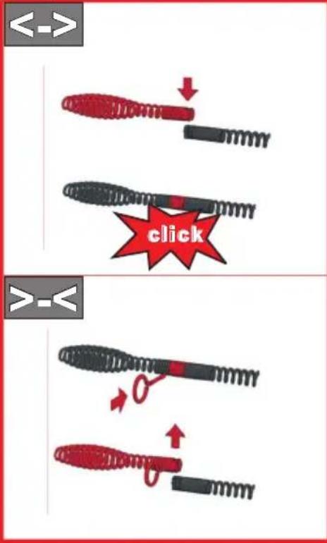
5.1 Use standard spirals (A)
The possible spiral diameters and spiral lengths that may be used are set out in the section entitled Technical data.
The spirals can be connected together at the coupling and subdivided again afterwards into segments using a separating pin; to do this insert the release wrench into the bore hole in the coupling and remove the coupling to the side.

Only use spiral sections for as long as is actually necessary!
Do not use deformed spirals!
→ Remove the spirals from the interior of the holding cage.
→ Push the spiral through the machine.
→ Attach the protective hose from the rear onto the machine and check the lock of the locking bolt.
Always use the protective hose. The protective hose acts as a vibration-damping guide for the spirals, as a dirt holder and guard, also as a safety element for the operating personnel and prevents uncontrolled banging!
5.2 Fit 8 mm / 10 mm spirals (B)
For small bore pipes and pipe bend used 8 mm or 10 mm spirals (optional accessories).
→ Pull the spirals approx. 30 cm out of the adapter magazine.
→ Push the adapter magazine into the machine from the rear and secure it. To brake the adapter magazine pull the lever as far upwards as possible.
5.3 Fit tools (C)
For first use to unfasten the plugging only use the drill with the smallest diameter and drill out the plugging hole for the first time. If the plugging hose has been bored or is opened and liquid begins to flow out, complete drilling out of the plugging hose with the largest possible adapted drill. If the plugging is now released, flush out and where possible, clean the pipe wall using a chain centrifuge drilling tool (where possible with water flowing through).
Depending on the type of blockage various tools may be secured to the standard spirals.
Straight drill: to establish the type of blockage
Club drill: can be used for minor textile and cellulose blockages as a result of its flexibility. The club shape enables it to get into tight pipe bends
Funnel drill: this is specifically used for textile and cellulose blockages. Its funnel-shape design gives this tool a large action range and allows it to be used as a tool to return spirals that have been trapped in the pipe

Fork cutting head: to remove grease deposits or shred lumps and similar materials

Shovel head drill: special bent tool for sludge or sand deposits
To secure: push the tool into the coupling until it engages.
To remove: push the release wrench into the hole and slide the tool sideways out of the coupling.
5.4 To adjust handle (D)
R650:
The handle can be fitted either at the top or at the side.
→ Move to the side position: Push the sleeve downwards, pull out the lever and insert it into the side opening.
→ Move to the top position: Pull out the lever, pull the sleeve downwards, insert the lever and lock the sleeve again.
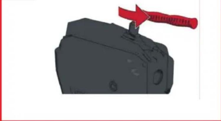
R750:
The handle can be turned forwards to allow the machine to be pulled more easily.
→ Push the sleeve downwards, pull out the lever, turn it through 180° and insert it again.

Turn the knurled bushing for securing or blocking and check that the clamping lever cannot be pulled!
5.5 Carry position (E)
The handle can be locked for carrying. To do this push the handle and pull the lock. To release the lock, press the handle briefly.
5.6 Safety gloves
Information brochure on safety gloves according to EC guideline 89/686/EWG.
Appendix II, Section 1.4 for minimal hazards only.
This pair of gloves is exempted under Chapter II, Article 8, Paragraph 3 of the prototype test and is assigned to Category 1. From this it is assumed that their effectiveness against minor hazard-free risks has been perceived.
The protection class is determined by the requirements, which may be of a mechanical, chemical or thermal nature or due to similar influences that do not call for a Category 2 protection class. A risk analysis must be carried out through a wearer trial if the required size is to be specified so that the glove fits. When using accessory parts, such as undergloves, it should be noted that function may be negatively affected.
The gloves must be properly stored, i.e. in boxes in dry spaces. Influences such as humidity, temperature, light and natural changes in materials over time may lead to changes in the characteristics. A shelf life cannot be specified, because that will depend on the degree of wear, and the amount and location of use.
Care with commercially available cleaning utensils (e.g. brushes, polishing cloths, etc.) is recommended. Washing or chemical cleaning requires prior consultation with an authorized technical workshop.
The manufacturer can accept no liability for changes in the characteristics. Before each time the gloves are used, check to make sure they are intact.
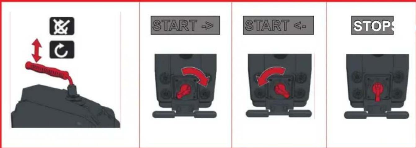
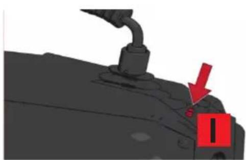
5.7 Start / Stop (F)
→ Switch the motor on and off at the switch:

Motor off

Turn clockwise;
remove blockages
Turn anti-clockwise, return jammed spirals
→ Start the spirals turning by pressing the handle.
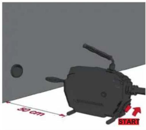
5.8 Operation (G)

Please ensure that the protective hose is attached to the machine.
→ Insert a suitable spiral, secure the protective hose and secure a suitable tool.
→ Position the machine max. 50 cm in front of the opening of the pipe you wish to clean. Set the machine to turn clockwise at the On/Off switch.
→ Insert the spiral approx. 50 cm into the pipe. Press the handle. The spiral will start to turn.

Guide the spiral only with the supplied special safety glove.
→ Release the handle and push the spiral further into the pipe. Repeat this process until you feel resistance; this means you have reached the blockage!
→ Pull the spiral out of the machine until the spiral is prestressed into a bend (working bend).

Do not create an operating arc which is too big – a risk of injury!
→ Press the handle and press the spiral against the blockage using the working bend.
→ When the spiral has moved into the pipe so far that the working bend is relieved, pull the spiral out of the machine and form a new working bend.
→ Repeat the process by pulling forward and backwards until the blockage has been removed, then release the handle and pull out the spiral.
If it does not move easily, press the handle and allow the spiral to turn briefly.
If the movement is very stiff, please ensure through clockwise and anticlockwise rotation that the spirals do not jam during locking (clockwise rotation) and releasing (anticlockwise rotation).

If the tool becomes fastened to the blockage, release the handle and switch the machine to turn anti-clockwise!
→ Using a back and forth type motion and clockwise and anticlockwise rotation of the spirals, release the tool from the plugging while the hand lever is depressed.
6 Care and Maintenance

Pull out the mains power plug before performing any servicing and maintenance!
Grease the machine with universal grease at the two lubrication points.
Lubrication point 1: daily or after every use.
Lubrication point 2: every 100 hours of service. Unscrew the left cover to access this point.
The device should be handled carefully and cleaned regularly.
The spirals and tools should be cleaned and preserved after every use. We recommend use of our special care product "ROWONAL".

All servicing, maintenance and repair work may only be performed by instructed specialist personnel!
7 Replace the calmp jaws
If the spirals no longer turn during operation and slip the clamping jaws are fouled with grease and must be cleaned or replaced if worn.
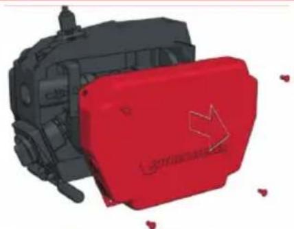
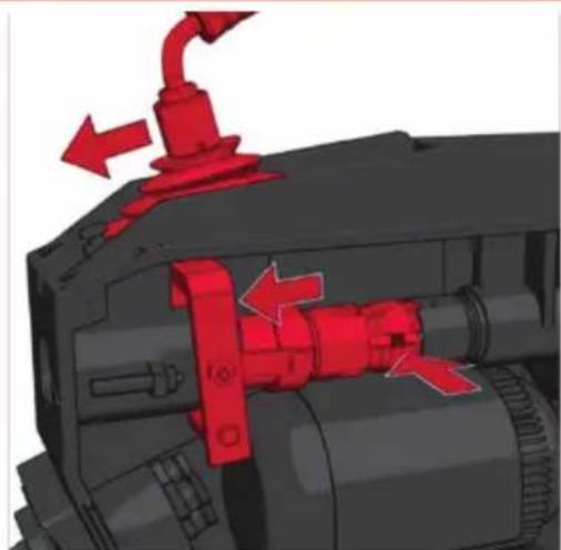
7.1 R550 - R650 (I)
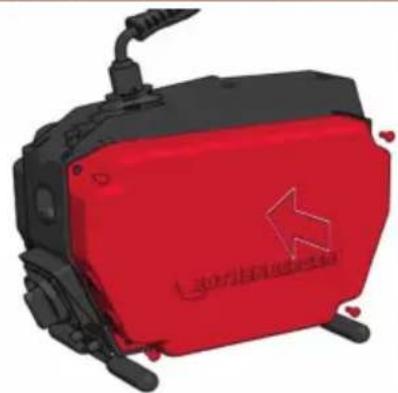
→ Unscrew the right cover.
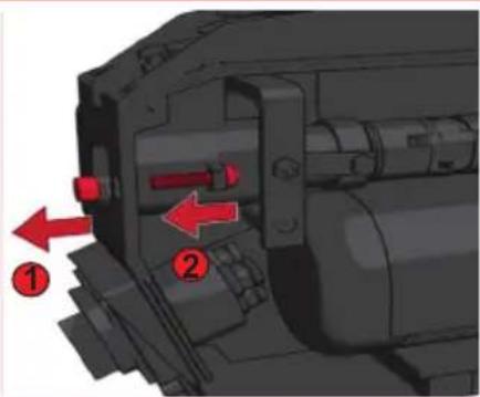
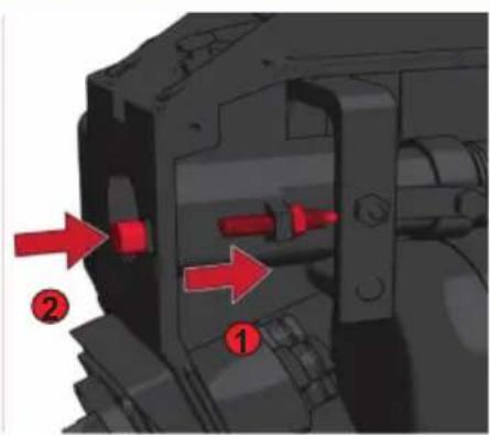
→ Remove the sealing stopper. Undo the lock nut and undo the adjusting screw until the clamp jaw springs are no longer stressed.
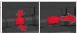
→ Pull the handle upwards and hold it in this position. Remove the clamp jaws. Press the clamp jaws together to release them.
→ Fit new clamp jaws.
→ Tighten the adjusting screws until the max. spiral diameter can still be inserted. Tighten the lock nut and insert the sealing stopped.
→ Secure the cover.
7.2 R750 (K)
→ Remove the cap with the two front screws.
→ Individually take out the clamps from the front. Then clean the housing and insert new clamping jaws one by one.
→ Screw on the cover and tighten the cover screws.
8 Accessories
| Accessory Name ROTHENBERGER Part Number | |
| Welder's glove, left 72120 | |
| Welder's glove, right 72121 | |
| ROWONAL rust remover (5 l) 72140 | |
| ROWONAL spiral combi-spray (0.2 l) 72142 | |
| Guide tube R550/ R600-650/ R750 72540/ 725 | 41/ 72559 |
| Segregation key ∅ 16/ 22-32/ 8 mm 72100/ 72 | 101/ 72102 |
| Clamping jaws R550/ R600-650/ R750 72538/ | 72638/ 72563 |
| Clamping jaws R750 72916 | |
| Adaptor MagazinesR550/ R600-650/ R750 725 | 11/ 72514/ 72515 |
| Ceramic Protection Hose 72705 | |
| Tripod Stand 58182 | |
| www.rothenberger.com | |
9 Customer service
The ROTHENBERGER service locations are available to help you (see listing in catalog or online) and replacement parts and service are also available through these same service locations.
Order your accessories and spare parts from your specialist retailer or using RoService+ online:
Phone: +49 (0) 61 95 / 800 - 8200
Fax: +49 (0) 61 95 / 800 - 7491
Email: service@rothenberger.com
www.rothenberger.com
10 Disposal
Components of the unit are recyclable material and should be put to recycling. For this purpose registered and certified recycling companies are available. For an environmental friendly disposal of the non-recyclable parts (e.g. electronic waste) please contact your local waste disposal authority.
For EU countries only:
Do not dispose electric tools with domestic waste. In accordance with the European Directive 2012/19/EU the disposal of electrical and electronic equipment and its implementation as national law, electric tools that are no longer serviceable must be collected separately and utilised for environmentally compatible recycling.
7.1 R550 - R650 (I) 29
7.2 R750 (K)....29
8 Accessoires 30
R550: 40-100mm, R600-650: 20-150mm, R750: 50-200mm
Email: service@rothenberger.com
www.rothenberger.com
R550: 40-100mm, R600-650: 20-150mm, R750: 50-200mm
Email: service@rothenberger.com
www.rothenberger.com
10 Eliminación
Email: service@rothenberger.com
www.rothenberger.com
10 Smaltimento
9 Klantenservice....60
R550: 40-100mm, R600-650: 20-150mm, R750: 50-200mm
Email: service@rothenberger.com
www.rothenberger.com
R550: 40-100mm, R600-650: 20-150mm, R750: 50-200mm
5.3 Inserir as ferramentas (C)
Email: service@rothenberger.com
www.rothenberger.com
10 Eliminação
R550: 40-100mm, R600-650: 20-150mm, R750: 50-200mm
Email: service@rothenberger.com
www.rothenberger.com
10 Affaldsbehandling
R550: 40-100mm, R600-650: 20-150mm, R750: 50-200mm
Email: service@rothenberger.com
www.rothenberger.com
10 Avfallshantering
R550: 40-100mm, R600-650: 20-150mm, R750: 50-200mm
Email: service@rothenberger.com
www.rothenberger.com
10 Avfallsdumping
R550: 40-100mm, R600-650: 20-150mm, R750: 50-200mm
Email: service@rothenberger.com
www.rothenberger.com
10 Kierrätys
R550: 40-100mm, R600-650: 20-150mm, R750: 50-200mm
Obroty robocze (min ^-1 )....575....460....620....460
Masa (kg) ok....15....20,9....22,8....29,5
Wielkość spirali (mm) .......Ø 16 ....... Ø 16/22 ....... Ø 16/22....... Ø 22/32
Email: service@rothenberger.com
www.rothenberger.com
10 Utylizacja
R550: 40-100mm, R600-650: 20-150mm, R750: 50-200mm
Email: service@rothenberger.com
www.rothenberger.com
10 Likvidace
R550: 40-100mm, R600-650: 20-150mm, R750: 50-200mm
Email: service@rothenberger.com
www.rothenberger.com
10 Atıklar İçin
R550: 40-100mm, R600-650: 20-150mm, R750: 50-200mm
Email: service@rothenberger.com
www.rothenberger.com
10 Ártalmatlanítás
E-post: service@rothenberger.com
www.rothenberger.com
10 Utiliseerimine
Darba ātrums (min ^-1 ) .....575.....460 .....620 .....460
Svars (kg) apm. 15 20,9 22,8 29,5
Spirāles izmērs (mm) .....Ø 16 ..... Ø 16/22 ..... Ø 16/22 ..... Ø 22/32
Spirāles izmērs ar piederumiem (mm)....Ø 8/10 ....Ø 8/10 ....Ø 8/10 ....Ø 8/10/16
Maks. darba garums (m)....40....60....65....80
Darba zona/caurułu diametrs (mm)....Ø 20-100 ....Ø 20-150 ....Ø 20-150 ....Ø 20-200
natural_image
Collection of metallic mechanical components with no visible text or symbolsE-pasts: service@rothenberger.com
www.rothenberger.com
10 Utilizácija
R550: 40-100mm, R600-650: 20-150mm, R750: 50-200mm
Email: service@rothenberger.com
www.rothenberger.com
R550: 40-100mm, R600-650: 20-150mm, R750: 50-200mm
ROTHENBERGER Worldwide
| Australia | ROTHENBERGER Australia Pty. Ltd.Unit 6 · 13 Hoyle Avenue · Castle Hill · N.S.W, 2154Tel. + 61 2 / 98 99 75 77 · Fax + 61 2 / 98 99 76 77rothenberger@rothenberger.com.auwww.rothenberger.com.au |
| South Africa | ROTHENBERGER-TOOLS SA (PTY) Ltd.P.O. Box 4360 - Edenvale 1610 |
| 165 Vanderbilt Street, Meadowdale Germiston Gauteng (Johannesburg), South AfricaTel. + 27 11/1/3 72 96 31 • Fax+ 27 11/1/3 72 96 32Info@rothenberger.co.za • www.rothenberger.co.za |
| Spain | ROTHENBERGER S.A.Ctra, Durango-Elomlo, Km 2 • E-48220 Abadiano (Vizcaya)(P.O. Box) 117 • E-48200 Durango (Vizcaya)Tel. +34 94//6 21 01 00 • Fax +34 94//6 21 01 3export@rothenberger.es • www.rothenbergeres |
| Sweden | ROTHENBERGER Sweden ABHemvärnsgatan 22 • S- 171 54 Solna, SverigeTel. + 46 8//54 60 23 00 • Fax + 46 8//54 60 23 01roswe@rothenberger.se • www.rothenberger.se |
| Switzerland | ROTHENBERGER (Schweiz) AGHerostr. 9 • CH-8048 ZürichTel. + 41 44//435 30 30 • Fax + 41 44//401 06 08Info@rothenberger-werkzeuge.ch |
| Turkey | ROTHENBERGER TÜRKIYEROTHENBERGER Center, Barbanos Bulvan Nr29TR-34775 Senfall / Ümranlıye-IstanbulTel. + 90// 216 449 24 85 · Fax + 90//216 449 24 87rothenberger@rothenberger.com.trwww.rothenberger.com.tr |
| UAE | ROTHENBERGER Middle East FZCOPO Box 261190 • Jebel Ali Free ZoneDubai, United Arab EmiratesTel. + 971//48 83 97 /77 -Flax+ 971//48 83 97 57office@rothenberger.ae |
| ROTHENBERGER EQUIPMENT TRADING & SERVICES LLCPO Box 91208 • Mussafah Industrial AreaAbu Dhabi, United Arab EmiratesTel. +971//25:50:01:54 •+971//25:50:01:58uaesales@rothenberger.ae |
| UK | ROTHENBERGER UK Limited2, Kingsthorne Park, Henson Way,Kettering • GB-Northants NN16 8PXTel. + 44 15 36//31 03 00 • Fax + 44 15 36//31 06 00Info@rothenberger.co.uk |
| USA | ROTHENBERGER USA LLC7130 Clinton Road • Loves Park, IL 611111,USATel. +1/80 05 45 76 98 • Fax + 1/81 56 33 08 79pIpetools@rothenberger-usa.comwww.rothenberger-usa.com |
| ROTHENBERGER Werkzeuge GmbH |
| Industriestraße 7 |
| D- 65779 Kelkheim / Germany |
| Telefon + 49 (0) 61 95 / 800 - 0 |
| Fax + 49 (0) 6195 / 800 - 3500 |
| info@rothenberger.com |

- Overview
- A Use standard spirals
- B Fit 8 mm / 10 mm spirals
- G Operating
- H Care and maintenance
- Replace the clamp jaws R550/R650 I
- Replace the clamp jaws R750
- Intro
- EU-DECLARATION OF CONFORMITY
- DECLARATION EU DE CONFORMITÉ
- Entsorgung
- Technical Data / Applications 15
- Scope of delivery....16
- Power connection....16
- Function of the Unit....16
- Care and Maintenance....19
- Replace the calmp jaws....19
- Accessories....20
- Customer service 20
- Disposal 20
- Markings in this document:
- General safety instructions
- Service and maintenance:
- Working safely:
- Special safety instructions
- Residual risks
- Intended use
- Technical Data / Applications
- Scope of delivery
- Power connection
- Putting the PRCD switch into operation
- Function of the Unit
- Use standard spirals (A)
- Fit 8 mm / 10 mm spirals (B)
- Fit tools (C)
- To adjust handle (D)
- R650:
- R750:
- Carry position (E)
- Safety gloves
- Start / Stop (F)
- Operation (G)
- Care and Maintenance
- Pull out the mains power plug before performing any servicing and maintenance!
- All servicing, maintenance and repair work may only be performed by instructed specialist personnel!
- Replace the calmp jaws
- R550 - R650 (I)
- R750 (K)
- Accessories
- Customer service
- Disposal
- For EU countries only:
- Accessoires 30
- Eliminación
- Smaltimento
- Klantenservice....60
- Inserir as ferramentas (C)
- Eliminação
- Affaldsbehandling
- Avfallshantering
- Avfallsdumping
- Kierrätys
- Utylizacja
- Likvidace
- Atıklar İçin
- Ártalmatlanítás
- Utiliseerimine
- Utilizácija
- ROTHENBERGER Worldwide
Brand : ROTHENBERGER
Model : R550
Category : Uncategorized