SWIFT 372e - Tractor STIGA - Free user manual and instructions
Find the device manual for free SWIFT 372e STIGA in PDF.
| Product type | Riding lawn tractor |
| Brand | STIGA |
| Model | SWIFT 372e |
| Power source | 48 V lithium-ion battery (BT 750/1 Li 48 or BT 775/1 Li 48) |
| Number of batteries | 3 (possible configurations 2 or 3 for reduced performance) |
| Battery charger | CGDF Li 48 (onboard or external optional) |
| Cutting height | 3 to 8 cm (6 positions) |
| Cutting width | Approximately 92 cm (not precise, estimate) |
| Forward speed | Variable (traction pedal) |
| Maximum slope allowed | 10 degrees (approximately 18%) |
| Traction motor | Electric, power not specified |
| Blade motor | Electric, power not specified |
| Cutting mode | ECO, NORMAL, TURBO (depending on panel version) |
| Special functions | Bluetooth, Cruise Control (on type II panel), USB port |
| Grass catcher | Included, with audible fill indicator |
| Options | Mulching kit, rear discharge protection kit, rapid charger, protection cover |
| Safety | Emergency stop, operator presence detection, micro-switches, automatic brake |
| Sound level (guaranteed sound power) | Not specified (see label) |
| Weight | Not specified (see label) |
| Dimensions (L x W x H) | Not specified (see manual) |
| Routine maintenance | Cleaning after each use, check of fasteners, tire pressure, battery charging |
| Periodic maintenance | Lubrication every 25h, sharpening/replacement of blades, annual cleaning of ventilation filters |
| Intended use | Lawn mowing and grass collection for residential (amateur use) |
Frequently Asked Questions - SWIFT 372e STIGA
User questions about SWIFT 372e STIGA
0 question about this device. Answer the ones you know or ask your own.
Ask a new question about this device
Download the instructions for your Tractor in PDF format for free! Find your manual SWIFT 372e - STIGA and take your electronic device back in hand. On this page are published all the documents necessary for the use of your device. SWIFT 372e by STIGA.
USER MANUAL SWIFT 372e STIGA
natural_image
Abstract line drawing of a stylized animal figure (no text or symbols)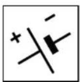

natural_image
Icon of a person reading a book inside a circle (no text or symbols)IT Tosaerba con conducente a bordo seduto, alimentato a batteria MANUALE DI ISTRUZIONI
ATTENZIONE: prima di usare la macchina, leggere attentamente il presente libretto.
BG Косачка със седнал водач, Акумулаторна УПЪТВАНЕ ЗА УПОТРЕБА
ВНИМАНИЕ: преди да използвате машината прочетете внимателно настоящата книжка.
BS Traktorska kosilica (traktorčić), na bateriju UPUTSTVO ZA UPOTREBU
PAŽNJA: prije nego što koristite ovu mašinu, pažljivo pročitajte priručnik s uputama.
CS Sekačka se sedící obsluhou, akumulátorový pohon NÁVOD K POUŽITÍ
UPOZORNĚNÍ: před použitím stroje si pozorně přečtěte tento návod k použití.
DA Havetraktor, batteridrevet BRUGSANVISNING
ADVARSEL: læs instruktionsbogen omhyggeligt igennem, før du tager denne maskine i brug.
DE Aufsitzmäher (Rasenmäher mit sitzendem Bediener, batterie betrieben) GEBRAUCHSANWEISUNG
ACHTUNG: vor inbetriebnahme des Geräts die Gebrauchsanleitung aufmerksam lesen.
EL Χλοοκοπτικό τρακτέρ με εποχούμενο χειριστή, μηχανή μπαταρίας ΟΔΗΓΙΕΣ ΧΡΗΣΠΣ
ΠΡΟΣΟΧΗ: πριν χρησιμοποιησετε το μηχανημα, διαβαστε προσεκτικα το παρον εγχειριδιο.
EN Ride-on lawnmower with seated operator, battery-operated OPERATOR'S MANUAL
WARNING: read thoroughly the instruction booklet before using the machine.
ES Cortadora de pasto con conductor sentado, alimentado con batería MANUAL DE INSTRUCCIONES
ATENCIÓN: antes de utilizar la máquina, leer atentamente el presente manual.
ET Istuva juhiga muruniitja, akutoitega KASUTUSJUHEND
TÄHELEPANU: enne masina kasutamist lugeda tähelepanelikult antud kasutusjuhendit.
FI Päältäajettava ruohonleikkuri, akkukäyttöinen
KÄYTTÖOHJEET
VAROITUS: lue käyttöopas huolellisesti ennen koneen käyttöä.
FR Tondeuse à gazon à conducteur assis, alimentation par batterie MANUEL D'UTILISATION
ATTENTION: lire attentivement le manuel avant d'utiliser cette machine.
HR Sjedeća kosilica trave s operaterom, baterijsko napajanje PRIRUČNIK ZA UPORABO
POZOR: prije uporabe stroja, pažljivo pročitajte ovaj priručnik.
2
8
natural_image
Technical line drawing of a mechanical device with labeled component E (no text or symbols beyond label)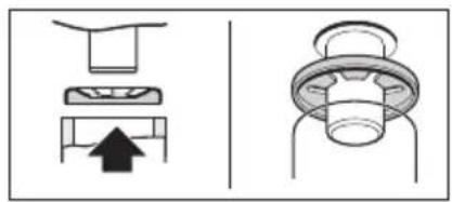
natural_image
Technical diagram showing three mechanical components with an upward arrow, no text or symbols present9
natural_image
Illustration of a car tire being adjusted for a valve, showing the wheel and handle (no text or symbols)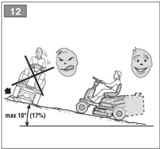
natural_image
Line drawing of a plug inserted into an electrical socket (no text or symbols)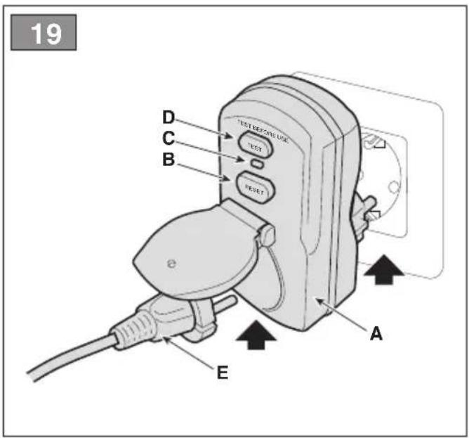
natural_image
Illustration of a car hood with a hand using a tool to clean or adjust the component (no text or symbols visible)


[14] Pumpetryk for fordæk
[15] Pumpetryk for bagdæk
[16] Vægt *
[7] Maximale Ladedauer
[42.A1] Mulching-Kit
[42.A2] Mulching-Kit
[2] MAX supply voltage
[3] NOMINAL supply voltage
[4] Max motor operating speed
[5] Battery
[6] Battery charger (CGDF Li 48)
[7] Maximum charge duration
[8] Drive motor power
[9] Blade motor power
[10] Radio equipment operating frequency bands
[11] Maximum radio frequency power transmitted in the frequency bands in which the radio equipment operates
[12] Front tyres
[13] Rear tyres
[14] Front tyre pressure
[15] Rear tyre pressure
[16] Mass *
[17] Minimum radius of uncut grass
[18] Cutting height
[19] Cutting width
[20] Work speed (indicative), in forward gear
[21] Work speed (indicative), in reverse gear
[22] Maximum permissible gradient
[23] Dimensions
[24] Length with grass catcher
[25] Width
[26] Height
[27] Cutting device part n.
[28] Sound pressure level (max.)
[29] Measurement uncertainty
[30] Measured acoustic power level (max.)
[31] Guaranteed acoustic power level
[32] Vibration level at driver's position (max.)
[33] Vibration level at steering wheel (max.)
[34] Table for the correct combination of batteries
[35] Battery combination for optimum machine performance
[36] Battery combination with reduced machine performance
[37] Battery combination that ensures only drive to be activated
[38] The use of a total of 3 batteries mounted on the machine (regardless of the combination) ensures the machine's functionality but with reduced performance
[39] The use of a total of 2 batteries mounted on the machine (regardless of the combination) ensures that only the drive function can be activated
[40] Important If only one battery is mounted, the machine will not work
[41] For the best performance, it is recommended that the batteries be fully charged
[42] Optional attachments
[42.A1] "Mulching" kit
[42.A2] "Mulching" kit
[42.B] Battery charger
[42.C] Canvas cover
[42.D] Rear unload protection kit
[43] Auxiliary socket for USB accessories
[43.A] Charging voltage and current (USB output)
[43.B] Type
[43.C] Name and address of Manufacturer
(a) Simultaneous charging of 2 BT 750/1 Li 48 batteries "on board" and 2 BT 775/1 Li 48 batteries on the "fast charger".
(b) A battery configuration different than the one specified constitutes prohibited use of the machine.
[1] ES - DATOS TÉCNICOS
[42.A1] Kit "mulching"
[42.A2] Kit "mulching"
[14] Esirehvide rōhk
[15] Tagarehvide rõhk
[16] Mass *
[1] FI - TEKNISET TIEDOT
[1] LT - TECHNINIAI DUOMENYS
[2] Maitinimo jtampa MAX
[3] Maitinimo jtampa NOMINAL
[4] Maksimalus variklio veikimo greitis
[5] Akumuliatorius
[6] Akumuliatoriaus jkroviklis (CGDF Li 48)
[42.A1] Kit "mulching"
[42.A2] Kit "mulching"
[42.B] Acculader
[42.C] Doek
[42.A1] Mulching-sett
[42.A2] Mulching-sett
[42.B] Batterilader
[42.C] Presenning
[42.A1] Kit "mulching"
[42.A2] Kit "mulching"
[42.B] Batteriladdare
[42.C] Skyddspressenning
[42.D] Skyddssats för bakre tömning
- USO DELLA MACCHINA 15
natural_image
Simple line drawing of a vehicle with four wheels and a downward arrow (no text or symbols)natural_image
Simple line drawing of a vehicle with four wheels and a downward arrow (no text or symbols)7. USO DELLA MACCHINA
AVVERTIMENTO
| Stato carica (SOC) Accensione led | |
| SOC > 80% | |
| 60% ≤ SOC < 80% | 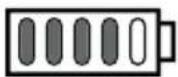 |
| 40% ≤ SOC < 60% | 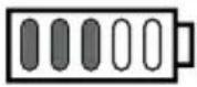 |
| 20% ≤ SOC < 40% |  |
| 10% ≤ SOC < 20% |  |
AVVISO
16.1 KIT PER MULCHING
natural_image
Simple line drawing of a vehicle with four wheels and a downward arrow (no text or symbols)natural_image
Simple line drawing of a vehicle with four wheels and a downward arrow (no text or symbols)b. Punjenje akumulatora izvan vozila
Za punjenje akumulatora:
- Otvorite vratašca (sl. 20.A) na kućištu akumulatora;
- Pritisnite dugme za otpuštanje na akumulatoru (sl.32.A) i izvadite akumulator (sl.32.B);
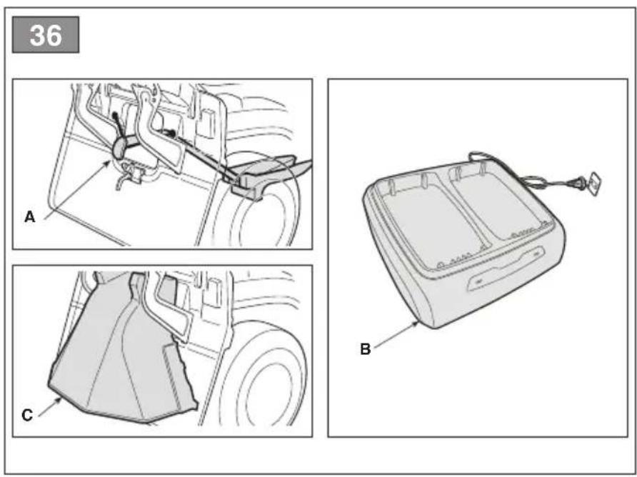
- Stavite akumulator (sl. 33.A) u odjeljak punjača akumulatora (sl. 33.B);
- Uključite punjač akumulatora (Sl. 33.B) u utičnicu, čiji napon se mora poklapati s naponom označenim na pločici;
- Napunite akumulator do kraja prema uputstvima iz priručnika za punjač akumulatora.
- Kad je punjenje završeno, uklonite akumulator (sl. 34.A) iz odjeljka punjača akumulatora (sl. 34.B);
- Isključite punjač akumulatora (Sl. 34.B) s električne mreže;
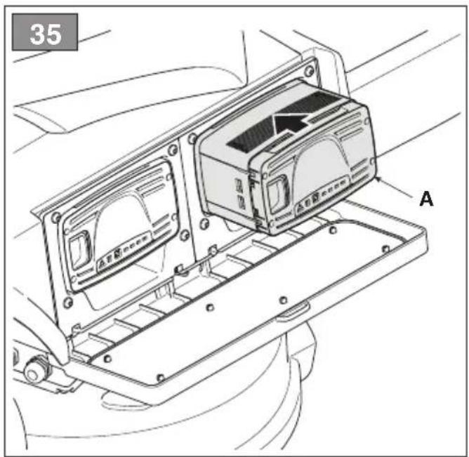
- Ponovo postavite akumulator (sl. 35.A) u kućište mašine i zatvorite vratašca odjeljka akumulatora.
| Stanje napunjenosti (SOC) | Led uključen |
| SOC > 80 % | |
| 60% ≤ SOC < 80% | |
| 40% ≤ SOC < 60% |  |
| 20% ≤ SOC < 40% |  |
| 10% ≤ SOC < 20% |  |

NAPOMENA
7.5 PRACOVNÍ ČINNOST
16.2 NABÍJEČKA (RYCHLÉ NABÍJENÍ)
16.1 KIT TIL "MULTICLIP"
16.3 KIT HINTERER AUSWURFSCHUTZ
-
GENERAL INFORMATION......2
-
GENERAL MACHINE SAFETY WARNINGS....2
-
SAFETY WARNINGS FOR RIDE-ON LAWN MOWER WITH SEATED OPERATOR....5
3.1 Training....5
3.2 Preliminary operations.... 5
3.3 During operation....6
3.4 Maintenance, storage....7
3.5 Environmental protection....7
- ABOUT THE MACHINE....8
4.1 Machine description and intended use....8
4.2 Safety signs....8
4.3 Identification label 9
4.4 Main components....9
- ASSEMBLY 10
5.1 Assembly components.... 10
5.2 Steering wheel assembly.... 10
5.3 Seat assembly.... 10
5.4 Mounting the grass catcher bag ..... 11
- CONTROLS 11
6.1 Key ignition switch 11
6.2 Drive pedal 11
6.3 Transmission engagement / disengagement lever 11
6.4 Cutting height adjustment lever ..... 11
6.5 Emergency button 12
6.6 Auxiliary socket for USB accessories 12
6.7 Warning buzzers....12
6.8 Pushbutton panel 12
6.9 Bluetooth function.... 15
- USING THE MACHINE....15
7.1 Preliminary operations.... 15
7.2 Safety checks....16
7.3 Using on slopes....17
7.4 Start-up 17
7.5 Operation.... 18
7.6 Stop....19
7.7 After use....19
- ROUTINE MAINTENANCE 19
8.1 General Information.... 19
8.2 Battery....20
8.3 Cleaning 22
8.4 Lubrication....23
8.5 Nuts and bolts 23
- OCCASIONAL MAINTENANCE....23
9.1 Safety recommendations.... 23
9.2 Cutting means assembly / cutting means 23
9.3 Replacing front / rear wheels 24
9.4 Replacing LED lamps 25
-
STORAGE 25
-
HANDLING AND TRANSPORT...... 25
-
ASSISTANCE AND REPAIRS......25
-
WARRANTY COVERAGE 26
-
MAINTENANCE TABLE 26
-
TROUBLESHOOTING 27
-
ATTACHMENTS 30
16.1 "Mulching" kit.... 30
16.2 Battery charger (fast charge).... 30
16.3 Rear discharge guard kit 30
1. GENERAL INFORMATION
1.1 HOW TO READ THIS MANUAL
Some of the paragraphs in this manual contain particularly important information in terms of safety and operation, and are highlighted differently, according to the following criteria:

DANGER
Failure to comply with this warning gives rise to an imminent risk situation which, if not prevented, causes instant death or serious/permanent injury.

WARNING
Failure to comply with this warning gives rise to a potential risk situation which, if not prevented, may cause instant death or serious harm to health.

ATTENTION
Failure to comply with this warning gives rise to a potential risk situation which, if not prevented, could cause minor damage to the machine.

NOTICE
Provides an instruction that indicates the need to deal with situations not related to physical injury.

SAFETY INSTRUCTION
Provides an instruction referring to specific procedures to be followed if situations arise that may endanger human health or the safety of machines.
NOTE
Provides additional information to the instructions provided in the previous safety messages.
The paragraphs highlighted in a dotted grey square indicate optional characteristics not available on all models documented in this manual. Check if this feature is available on this model.
Whenever reference is made to a position on the machine "front", "back", "left" or "right" hand side, this refers to the operator's working position.
1.2 REFERENCES
1.2.1 Figures
The figures in these instructions for use are numbered 1, 2, 3, etc. Components shown in the figures are marked A, B, C, etc. Reference to component C in figure 2 is indicated with the wording: "See fig. 2.C" or simply "(Fig. 2.C)". The figures are provided by way of example. The actual pieces can differ from those illustrated in this document.
1.2.2 Titles
The manual is arranged in chapters and paragraphs. The title of paragraph '2.1 Training" is a sub-title of "2. Safety regulations". References to titles or paragraphs are marked with the abbreviation chap. or par. and the relevant number. Example: "chap. 2" or "par. 2.1"
2. GENERAL MACHINE SAFETY WARNINGS
2.1 GENERAL SAFETY WARNINGS
WARNING
Read all safety warnings, instruction, illustrations and specifications supplied with the machine. Failure to follow all instructions listed below may result in electric shock, fire and/or serious injury.
Save all warnings and instructions for future reference.
The term "power tool" indicated in the warnings refers to a machine powered through the electricity mains (with a power cable) or battery-powered equipment (without cable).
1) Work area safety
a) Keep the work area clean and well illuminated. Untidy or dark areas may cause accidents.
b) Do not use power tools in explosive atmospheres, such as in the presence of flammable liquids, gases or powder. Power tools create sparks which may ignite the dust or fumes.
c) Keep children and bystanders well away while using power tools. Distractions can cause you to lose control.
2) Electrical safety
a) The battery charging cable plug must match the outlet. Never modify the plug in any way. Do not use any adapter plugs with the earthed (grounded) battery charge cable. Unmodified plugs and matching outlets will reduce the risk of electric shocks.
b) Avoid body contact with earthed or grounded surfaces, such as pipes, radiators, cookers and refrigerators. There is an increased risk of electric shock if your body is earthed or grounded.
c) Do not expose power tools to rain or wet environments. Water entering a power tool will increase the risk of electrical shock.
d) Never pull on the cord to remove the plug from the socket. Keep the battery charge cable away from heat, oil, solvents, sharp objects, sharp edges or moving parts. Damaged or entangled cords increase the risk of electric shocks.
e) Do not use the cable improperly. Do not use the cable to carry, pull or disconnect the tool from the socket. Keep the cable away from heat, oil, sharp edges or moving parts. Damaged or entangled cords increase the risk of electric shocks.
f) When using the power tool outdoors, use an extension cable suitable for outdoor use. Using an extension cable suitable for outdoor use reduces the risk of electric shock.
g) If using a power tool in a humid environment cannot be avoided, use a power outlet protected by a residual current device (RCD). Using an RCD reduces the risk of electric shock.
h) Only connect the battery charger to a socket with the mains frequency as indicated on the name plate.
DANGER
Moisture and electricity are not compatible:
- Make sure your hands are dry when handling and connecting the electrical cables.
- Never connect an electrical socket or a cable in a wet area (presence of puddles or damp terrain).
- If necessary, use an extension cord with integrated watertight and type-approved sockets, available on the market.
- The pre-installation of a charging socket, connected to the mains power network of the building must be carried out by a qualified electrician and must be suitably protected by a differential switch (RCD-Residual Current Device) with a release current compliant with legislation in force.
- Incorrect connection can cause short circuits and serious personal injury, including death.
• To prevent interruptions in the supply of electrical power during charging operations:
- check that the overall capacity of the electrical system is suitable.
- connect the machine to a power socket with sufficient amperage.
- avoid simultaneous use of other electrical appliances with high energy draw.
3) Personal safety
a) Stay alert, check what you are doing and use common sense when using a power tool. Do not use the power tool when you are tired or under the influence of drugs, alcohol or medicines. A moment of inattention while operating a power tool may result in serious personal injury.
b) Use personal protective equipment (PPE). Always wear eye protection. Using protective equipment such as a dust mask, non-slip safety shoes, hard hat or hearing protection helps prevent personal injuries.
c) Avoid unintentional starting. Make sure that the switch is in the "OFF" position before inserting the plug, holding or carrying the electric power tool. Carrying an electric tool with your finger on the switch or connecting to the mains socket with the switch in the "ON" position makes accidents more likely.
d) Remove any adjustment spanner or tool before switching the power tool on. A wrench or a tool left attached to a rotating part of the machine may result in personal injury.
e) Do not lean out. Keep proper footing and balance at all times. This ensures better control of the power tool in unexpected situations.
f) Dress appropriately. Do not wear loose clothes or jewellery. Keep hair and clothing away from moving parts. Loose clothes, jewellery or long hair can be caught in moving parts.
g) If devices have to be connected to powder extraction and collection systems, make sure they are connected and used appropriately. Using these devices may reduce powder-related hazards.
h) Do not allow familiarity acquired while using the machine to become complacent and ignore the safety principles of the power tool. A careless action can cause severe injury in a fraction of a second.
4) Using and looking after power tools
a) Do not over-charge the power tool. Use a power tool appropriate for the task in question. The correct power tool will do the job better and safer at the speed for which it was designed.
b) Do not use the power tool if the switch does not turn it on and off. Any power tool that cannot be controlled with the switch is dangerous and must be repaired.
c) Do not use the machine if the key ignition switch does not turn it on and off. A machine which cannot be controlled with the key switch is dangerous and must be repaired at an Authorised Service Centre.
d) Remove the ignition key before making any adjustments, changing accessories, or before putting the power tool away. These preventive safety measures reduce the risk of accidental start-up of the power tool.
e) Store unused power tools out of the reach of children and do not allow persons who are not familiar with using the machine and these instructions to use it. Power tools are dangerous in the hands of untrained users.
f) Ensure regular maintenance of power tools and accessories. Check for misalignment or binding of moving parts, breakage of parts and any other condition that may affect power tool operation. In case of damage, the power tool must be repaired before it can be used. Many accidents are caused by poor maintenance.
g) Keep cutting tools sharp and clean.
Properly maintained cutting tools with sharp cutting edges are less likely to bind and are easier to control.
h) Use the power tool and its accessories in accordance with these instructions, taking into account the working conditions and the task to be performed. Using the power tool for operations other than those intended could result in a hazardous situation.
i) Keep handles and grasping surfaces dry, clean and without any trace of oil or grease. Slippery grips and gripping surfaces do not allow safe movement and control of the tool in unexpected situations.
5 Using and looking after battery-operated tools
a) Charge the batteries only by using the battery chargers recommended by the manufacturer. A battery charger suitable for one type of battery may create a risk of fire, electric shock, overheating or leakage of corrosive liquid from the battery if used with another type of battery.
b) Use only batteries specifically designed for your power tool. Using any other type of battery may create a risk of injury and fire.
c) When the batteries are not in use, they should be kept away from other metal objects such as paper clips, coins, keys, nails, screws or other small metal objects that could short-circuit the contacts. Short circuits between battery contacts can lead to explosion or fires.
d) A battery in poor condition may allow fluid to leak from it. Avoid contact with battery fluids. In case of accidental contact, rinse with water. If battery fluids come into contact with the eyes, also consult a doctor. Liquid leaked from the battery may cause skin irritation or burns.
e) Do not use a machine or battery pack that are damaged or modified. Damaged or modified batteries may exhibit unpredictable behaviour resulting in fire, explosion or risk of injury.
f) Do not expose the batteries or the tool to fire or excessively high temperatures. Exposure to fire or temperatures exceeding 130^ C may cause an explosion.
g) Follow all the charging instructions and do not charge the battery outside the temperature range specified in the instructions. Improper charging or at temperatures outside the specified range can damage the batteries and increase the risk of fire.
h) Do not charge the batteries in places with vapours or flammable substances present or in rooms which are damp. If it is not possible to avoid damp environments, use a power socket protected by a differential switch (RCD-Residual Current Device) to reduce the risk of electric shocks.
i) Keep the battery charge cable out of the reach of children.
6) Technical Assistance
a) Have your power tool serviced by a qualified repair person using only identical replacement parts. This will ensure that the safety of the power tool is maintained.
b) Do not attempt to repair batteries. Repairs must be carried out by the manufacturer or by a specialized service centre.
3. SAFETY WARNINGS FOR RIDE-ON LAWN MOWER WITH SEATED OPERATOR
3.1 TRAINING
- Become acquainted with the controls and the proper use of the machine. Learn how to stop the machine quickly.
- Never allow the machine to be used by children or individuals who are not familiar with the instructions. Local laws may establish a minimum age for users.
- Do not allow children or other passengers to ride on the machine.
- Bear in mind that the user is responsible for accidents or unexpected events occurring to other people or their property. It is the user's responsibility to assess the potential risk of the area where work is to be carried out and to take all the necessary precautions to ensure his own safety and that of others, particularly on slopes or rough, slippery and unstable ground.
- This manual is an integral part of the machine and therefore must always be accompany it in the case of temporary or definitive transfer.
3.2 PRELIMINARY OPERATIONS
Personal Protective Equipment (PPE)
- Wear suitable clothing, strong work shoes with anti-slip soles, and long pants. Do not operate the machine barefoot or wearing open sandals. Wear hearing protection devices.
- Use of hearing protections can reduce the ability to hear any warnings (shouting or alarms). Be careful of what occurs around you in the work area.
- Never wear scarves, shirts, necklaces, bracelets, loose flowing clothing, laces or ties or any hanging or flapping accessory that could catch in the machine or in any objects or materials in the work area.
- Tie up long hair.
Work / Machine Area
Thoroughly inspect the entire work area and remove anything that could be thrown by the machine or damage the cutting means/rotating units (stones, branches, iron wire, bones, etc.).
3.3 DURING OPERATION
Work Area
- Do not use the machine in environments that pose the risk of explosion, in the presence of flammable liquids, gases or powders. Electrical contact or mechanical rubbing can generate sparks that can ignite powder or vapour.
- Work only in daylight or with good artificial light in good visibility conditions.
- Keep people, children and animals away from the work area. Children must be supervised by another adult.
- Avoid working with wet grass, in the rain and when there is a risk of a thunderstorm, and especially of lightning.
- Pay careful attention to uneven ground (hills, dips), slopes, hidden hazards and obstacles that could limit visibility.
- Be very careful near ravines, ditches or embankments. The machine could overturn if a wheel slides over the edge or if the earth gives way.
- Pay close attention on sloping ground which requires special care to prevent overturning or loss of control of the machine. The main reasons for loss of control are:
- Insufficient wheel grip.
- Excessive speed.
- Sharp changes of direction.
- Inadequate braking.
- Type of machine unsuitable for its task.
- Lack of awareness of the effect of ground conditions.
• Using the machine for towing.
- Look out for traffic when using the machine near the road.

NOTICE
The machines detailed in this manual are not designed for use as towing vehicles.
Conduct
- When working behind the wheel, do not become distracted and maintain the required level of concentration.
-
Exercise caution when reversing or moving backwards. Look behind you to make sure there are no obstacles before and during operations in reverse gear.
-
Pay careful attention when using the attachments that can alter the stability of the machine, especially on slopes.
- Always keep hands and feet away from the cutting means, when starting and when using the machine.
- Keep hands and feet away from the seat support. There is the risk of crushing injuries.

WARNING
the cutting means will continue to rotate for a few seconds after disengagement or after switching off the motor.

WARNING
Pay attention to the cutting means assembly with more than one cutting element, since one rotating cutting means can trigger rotation of the others.

SAFETY INSTRUCTION
If something breaks or an accident occurs during work, turn off the motor immediately and move the machine away to prevent further damage; if an accident occurs with injuries or third parties are injured, carry out the first aid measures most suitable for the situation immediately and contact the medical authorities for any necessary health care. Carefully remove any debris which could cause damage or injury to persons or animals if ignored.
Restrictions of use
- Never use the machine with damaged, missing or incorrectly positioned guards (grass catcher, rear unload guard)
- Don't use the machine if the attachments/tools are not installed in their seats.
- Never disengage, deactivate, remove or tamper with the safety systems/micro switches installed.
- Do not strain the machine too much and do not use an inappropriate machine for heavy-duty work; if you use the correct machine, you will reduce the risk of hazards and improve the quality of your work.
- The machine has not been type-approved for circulation on public roads. It must be used (as indicated by the highway code) in private areas closed to traffic.
3.4 MAINTENANCE, STORAGE
Ensure regular maintenance and correct storage to maintain machine safety and high performance levels.
Maintenance
- Never use the machine with worn or damaged parts. Faulty or worn-out parts must always be replaced and never repaired.
- Be careful during adjustment of the machine to prevent entrapment of the fingers between moving parts of the cutting means and fixed parts of the machine.
- Have your machine serviced by a qualified repair person using only identical replacement parts. This will ensure that the safety of the machine is maintained.
- Do not attempt to repair batteries. Repairs must be carried out by the manufacturer or by a specialized service centre.

SAFETY INSTRUCTION
The noise and vibration levels shown in these instructions are the maximum levels when using the machine. The use of an unbalanced cutting element, the excessive speed of movement, or the absence of maintenance have a significant influence on noise emissions and vibrations. Consequently, it is necessary to take preventive steps to eliminate possible damage due to high levels of noise and stress from vibration; maintain the machine well, wear ear protection devices, and take breaks whilst working.
Storage
To reduce fire risks, do not leave containers with debris inside a room.
3.5 ENVIRONMENTAL PROTECTION
Protecting the environment must be a significant and top priority for machine use, to the benefit of civil co-habitation and of the environment that we live in.
- Scrupulously comply with local regulations for the disposal of packaging, deteriorated parts or any elements with a strong environmental impact; this waste must not be disposed of with regular waste, but must be separated and taken to collection centres, which will recycle the materials.
- Comply with local regulations for the disposal of waste materials.
- When the machine is withdrawn from service, do not dispose of it in the environment, but take it to a waste disposal facility in accordance with the local regulations in force.
Do not throw electrical equipment away with domestic waste. In observance of European Directive 2012/19/EU on electrical and electronic equipment waste and its implementation, in observance of UK Regulation “The waste electrical and electronic equipment regulations 2013 (as amended)” and in accordance with national regulations, old electrical equipment must be collected separately, for eco-compatible recycling. If electrical equipment is disposed of in dumps or in landfills, hazardous substances can leak into the groundwater and contaminate the food chain, damaging your health and well-being. For further information on the disposal of this product, contact your dealer or a domestic waste collection service.
At the end of their working life, dispose of batteries with all due care and in compliance with applicable local legislation. Batteries contain materials classified as hazardous for people and
the environment. They must be removed and disposed of separately at a facility that accepts lithium-ion batteries.

Separate waste collection of the products and packaging used allows the materials to be recycled and reused. Reuse of recycled materials help to prevent environmental pollution and reduces the d for raw materials.
4. ABOUT THE MACHINE
4.1 MACHINE DESCRIPTION AND INTENDED USE
This machine is a ride-on lawn mower with seated operator.
The machine is equipped with electric motors that drive the cutting means and an electric drive motor.
The machine has rear-wheel drive.
The operator is able to operate the machine and use the main controls, always seated in the operator's position.
The safety devices installed on the machine will disengage the engine and cutting means in a couple of seconds (par. 7.2.2).
4.1.1 Intended use
This machine was designed and built to cut grass and in particular to: .
- mow the grass and collect it in the grass catcher;
- mow the grass and discharge it on to the ground through the rear part (if available).
- mow the grass, chop it and discharge it on the ground (mulching effect, if available).
The use of special attachments provided for by the Manufacturer as original equipment or which may be purchased separately, allows this work to be done in various operating modes, illustrated in this manual or the instructions that accompany the single attachments. Likewise, the intended use can be extended to include other functions by applying supplementary attachments (if provided for by the Manufacturer), abiding by the restrictions and conditions indicated in the instructions accompanying the attachment.
4.1.2 Improper use
Any use other than those mentioned above may be hazardous and cause harm to persons and/or damage things. Examples of improper use may include, but are not limited to:
- Allowing children, animals or other passengers on the machine as they could fall off and injure themselves or compromise safe driving by the operator;
- push loads;
- using the machine for riding over unstable, slippery, icy, stony, rough, marshy ground or puddles that do not allow the consistency of the ground to be assessed;
• Using the cutting means on surfaces other than grass;
• Using the machine for leaf or debris collection; - using a battery other that the specified configuration (see technical data section).
NOTICE
Improper use of the machine will void the warranty and relieves the Manufacturer of any liability, placing all responsibility for damage or injury, to him/herself or third parties, on the user.
4.1.3 Type of users
This machine is intended for use by consumers, i.e. non-professional operators. It is intended for "hobby use" and must be only used by a single operator.
4.2 SAFETY SIGNS
The machine has various symbols on it (fig. 2). Their function is to remind the operator of the correct conduct for use, with due care and caution.
Meanings of the symbols:
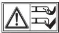
ATTENTION
Read the instructions before use.
ATTENTION
Remove the key and read the instructions before carrying out any maintenance or repair work.
HAZARD OF EJECTED OB- JECTS.
Do not operate without either the rear discharge guard or the grass catcher being in place.
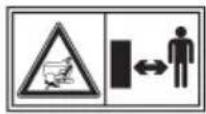
HAZARD OF EJECTED OBJECTS.
Keep all persons away and outside the work area during machine use.
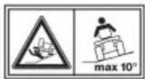
RISK OF MACHINE ROLL-OVER:
Do not use the machine on gradients in excess of 10^ .
CRUSHING HAZARD
Make sure that children remain at a safe distance from the machine when the engine is running.
CUTTING HAZARD
Cutting means in operation. Do not insert hands or feet into the cutting means housing.

SAFETY INSTRUCTION
Any damaged or illegible decals must be replaced. Order replacement decals from an Authorised Service Centre.
4.3 IDENTIFICATION LABEL
The identification label includes the following data (fig. 1):
- Sound power level.
- Conformity marking
- Year of manufacture.
- Type of machine.
- Serial number.
- Name and address of Manufacturer.
- Article code.
- Max. motor operation speed.
- Weight in kg.
- Electrical protection rating.
- Rated voltage.
- Battery capacity.
Write the identification data of the machine in the specific space on the label on the back of the cover page.

SAFETY INSTRUCTION
State the identification data on the product identification label whenever you contact an Authorised Service Centre.
NOTE
An example of the Declaration of Conformity is provided on the last pages of this manual.
4.4 MAIN COMPONENTS
The machine comprises the following main components having the following functions (Fig.1):
A. Cutting means assembly: this is the assembly comprising the casing housing the rotating cutting means assembly and the cutting means.
B. Cutting means: these are what cut the grass; the fins at the ends help convey the cut grass towards the discharge chute.
C. Discharge chute: the is the connecting element between the cutting means assembly and the grass catcher.
D. Grass catcher: apart from collecting the cut grass, it also constitutes a safety element, preventing any objects picked up by the cutting means from being propelled away from the machine.
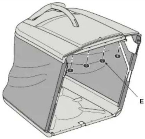
E. Rear discharge guard (available upon request): mounted in place of the grass catcher, it prevents any objects picked up by the cutting means from being propelled away from the machine.
F. Driving seat: this is where the machine operator sits. It has a sensor connected to safety devices for detecting the presence of the operator.
G. Blade motors: drive the cutting means.
H. Drive motor: drives the wheels.
I. Batteries: provide power to the motor and all electrical components of the machine.
J. Steering wheel: turns the front wheels.
K. Pushbutton panel : interface comprising all the main commands for using the machine.
5. ASSEMBLY
WARNING
The safety regulations to be followed are described in chapter 2. Strictly comply with these instructions to avoid serious risks or hazards. Do not use the machine until all the instructions provided in the "ASSEMBLY" section have been carried out.
For storage and transport purposes, some components of the machine are not installed in the factory and have to be assembled after unpacking.
Unpacking and completing the assembly should be performed on a flat and stable surface, with enough space for moving
the machine and its packaging, always making use of suitable equipment.
5.1 ASSEMBLY COMPONENTS
The packaging holds the components needed for assembly as listed in the table below:
| Description | |
| 1 Steering wheel and mounting components | |
| 2 Driving seat | |
| 3 Battery charger | |
| 4 Bag with mounting nuts and bolts and instructions | |
| 5 Envelope containing:- the instruction manuals and documents- driving seat assembly screws- 2 starter keys | |
| 6 Mobile phone holder kit (if provided). | |
5.1.1 Unpacking
- Carefully open the packaging, paying attention not to lose components.
- Consult the documentation in the box, including these instructions.
- Remove all the unassembled parts from the box.
-
Remove the machine from the packaging taking the following precautions:
-
move the cutting means assembly to its maximum height (par. 6.4) to protect it against damage when the machine is lifted off the base pallet;
- Move the front drive release lever to the released position (par. 6.3);
- Lift the machine off the base pallet.
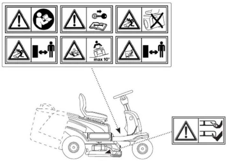
5.2 STEERING WHEEL ASSEMBLY
First of all, put the machine on a flat surface and straighten the front wheels. Then:
Only for type "I" steering wheel
- Fit the support (fig. 3.B) on the steering shaft (fig. 3.A).
- Fit the hub (fig. 3.C) on the steering support (fig. 3.B) making sure that the pin (fig. 3.G) is correctly inserted into its seat (fig. 3.C) in the hub.
-
Fit the steering wheel (fig. 3.D) on the hub (fig. 3.C) with the spokes pointing towards the seat.
-
Fasten the steering wheel (Fig. 3.C) on the support (Fig. 3.D) using the supplied screws (Fig. 3.E) in the sequence indicated.
- Replace the cap on the steering wheel (fig. 3.1) inserting with a click into its seat.
Only for steering wheel type "II"
- Fit the hub (fig. 3.B) on the steering shaft (fig. 3.A) making sure that the pin (fig. 3.C) is correctly inserted into its seat in the hub.
- Fit the steering wheel (fig. 3.D) on the hub (fig. 3.B) with the spokes pointing towards the seat.
- Fasten the steering wheel (Fig. 3D) on the support (Fig. 3A) using the supplied screws (Fig. 3.E) in the sequence indicated.
- Fit the mobile phone holder (fig. 3.F) making sure that it is correctly inserted in its seat on the steering wheel (fig. 4.F, D).
- Fit the mobile phone holder cap (fig. 3.G) making sure that it is correctly inserted in its seat on the steering wheel (fig. 4 G, .F).
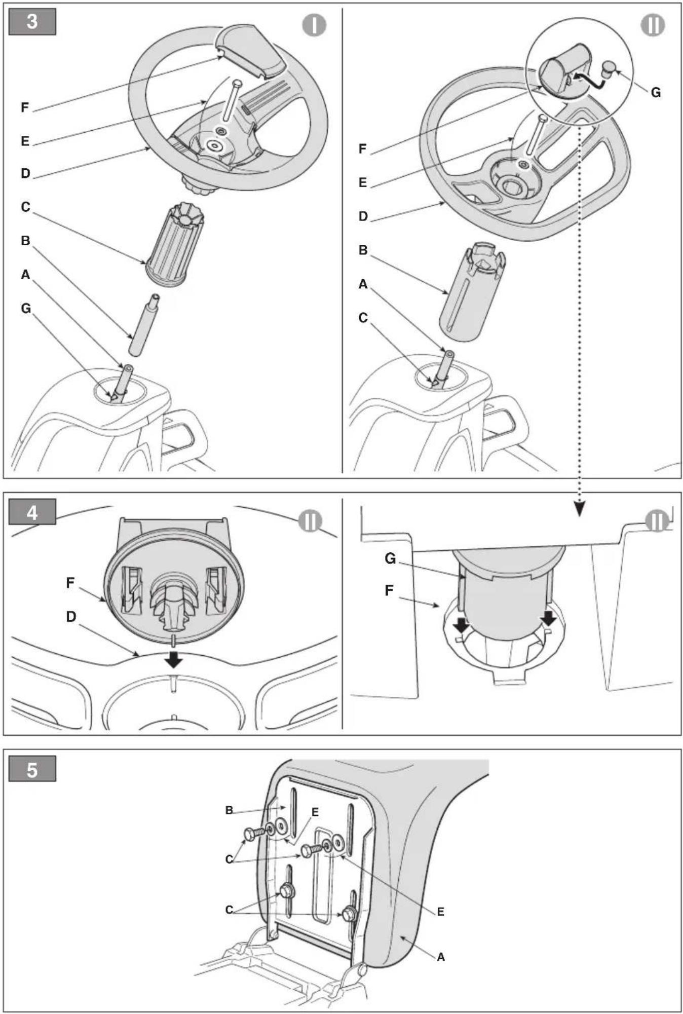
5.3 SEAT ASSEMBLY
Mount the seat (fig. 5.A) on the base plate (fig. 5.B) using the screws (fig. 5.C) and the other small parts supplied (fig. 5.E) in the sequence indicated.
5.4 MOUNTING THE GRASS CATCHER BAG
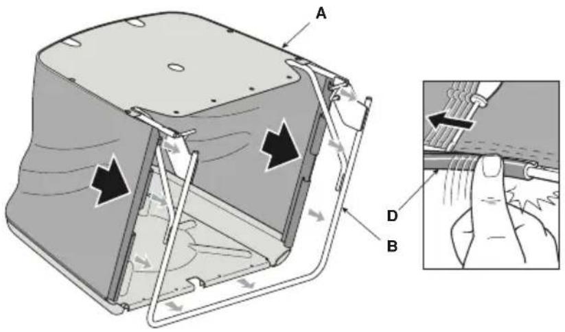
- Insert the canvas (fig. 8.A) for the grass catcher on the frame (fig. 8.B) and secure it with the specific perimeter closures (fig. 8.D).
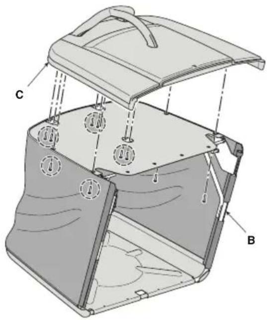
- Fit the cover (fig. 8.C) on the frame (fig. 8.B) using the screws supplied in the quantity and positions indicated.
- Secure the canvas (fig. 8.A) on the cover (fig. 8.C) using the rings supplied (fig. 8.E) in the quantity and positions indicated.
6. CONTROLS
6.1 KEY IGNITION SWITCH
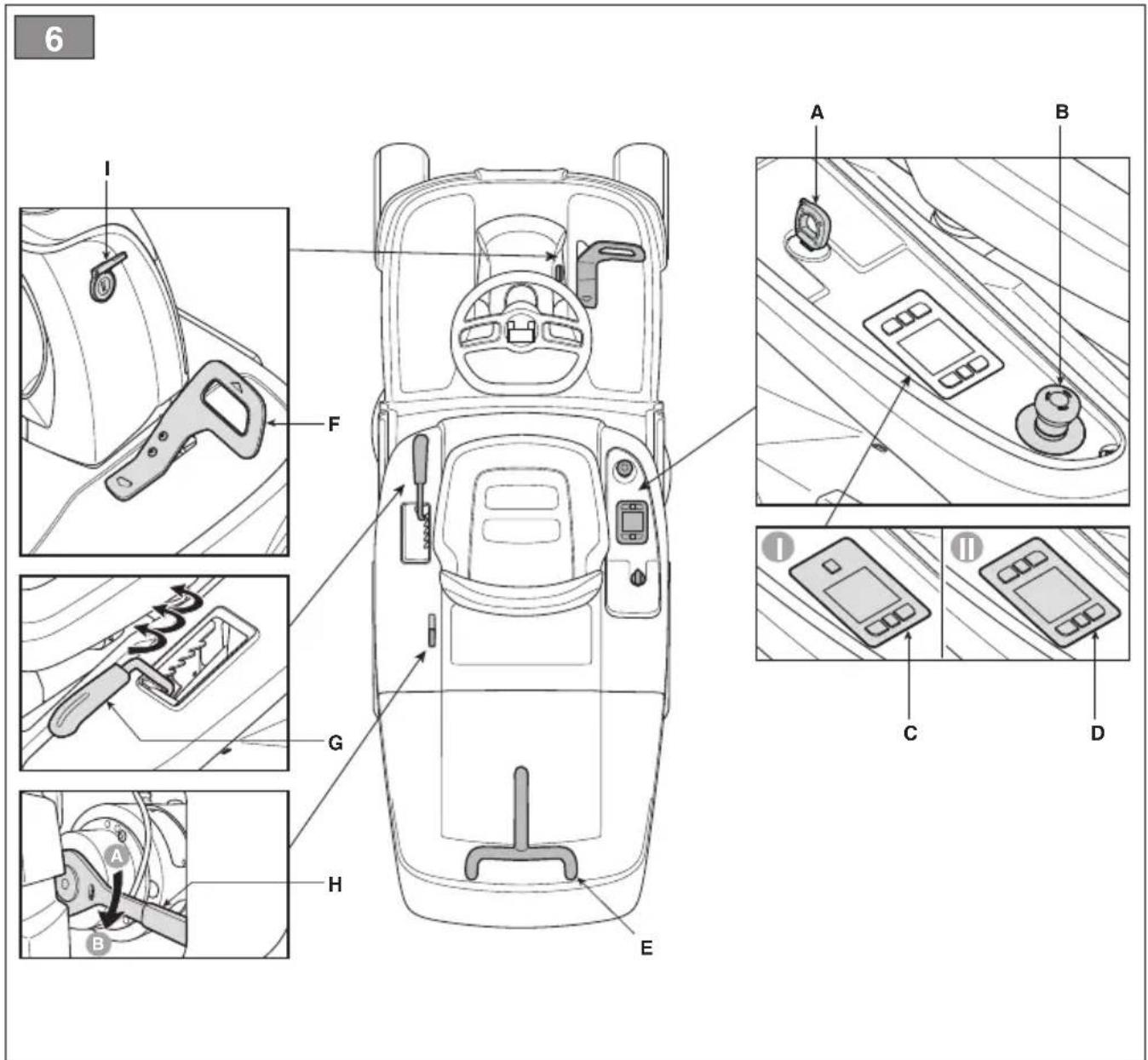
This key-operated command serves as the main switch to enable or dis-enable the machine's ignition circuit. The key-operated switched (fig. 6.A) has 2 positions:
- Key removed. The power circuit is disabled and the machine turns off. No function can be activated.
- Key fully inserted. The machine is ready to be turned ON.
6.2 DRIVE PEDAL
The drive pedal (Fig. 6.A.) activates wheel drive and adjusts machine speed in forward and reverse gears.
- Forward drive gear: by pressing the pedal forwards, the machine advances. Increasing the pressure on the pedal progressively increases the speed of the machine.
-
Reverse drive gear: by pressing the pedal backwards, the machine moves in reverse gear. Reducing the pressure on the pedal progressively reduces the speed of the machine.
-
Parking: when the pedal is released, a service brake engages automatically which serves to decelerate and stop the machine, preventing any additional movement until the drive pedal is once again pressed.
NOTE
Drive disengages when the operator leaves the seat.
6.3 TRANSMISSION ENGAGEMENT / DISENGAGEMENT LEVER
The transmission engagement/disengagement lever (Fig. 6.E) allows the machine to be moved manually (pushed or towed) without having to switch on the machine. This command has two positions:
- Drive engaged: move the lever (fig. 6.H) into the horizontal position (A). The machine can be moved normally by starting the machine.
- Transmission disengaged: move the lever (fig. 6.H) downwards (B). The machine can be moved manually without having to start the machine.
WARNING
Only move the machine manually on a level surface.
SAFETY INSTRUCTION
The engagement/disengagement lever must never be in the intermediate position. This condition will cause overheating and damage the transmission.
6.4 CUTTING HEIGHT ADJUSTMENT LEVER
This lever (fig. 6 G) is used to raise and lower the cutting means assembly, which may be positioned at 6 different cutting heights between 3 and 8 cm.
To move from one position to another, the lever must be moved sideways and repositioned in one of the stop notches.
6.5 EMERGENCY BUTTON
The emergency button (Fig. 6.B) allows the machine to be stopped immediately in the event of an emergency. The button has two positions:

- Activated: pressing the emergency button stops the cutting means motors and drive control devices.

- Deactivated: turn the emergency button clockwise to deactivate it and restore all functions. To start the machine, repeat the starting procedure (par.7.4).
NOTE
The machine cannot be started when the emergency button is activated.
NOTICE
The emergency button should never be used as a routine method for stopping the machine.
6.6 AUXILIARY SOCKET FOR USB ACCESSORIES
This socket (fig. 6.1) can charge USB devices. It only has a recharging function. The socket has no communication function with the connected USB device.
The socket is only live when the key (fig. 6.A) is fully inserted.
Do not recharge the accessory connected to the USB socket in rainy, humid or high temperature conditions with direct exposure to sunlight. Use in these conditions invalidates the warranty and waives the Manufacturer from any liability in the event of problems.
Do not open the USB plug in rainy or dusty areas.
The Manufacturer declines any and all liability in the event of damage to the accessory connected to the USB socket or loss of data during its use.
6.7 WARNING BUZZERS
- A double buzzer signal indicates that the grass catcher has not been fitted. Check the presence or correct assembly of the grass catcher or the presence of the rear unload guard kit (see par. 16.3).
- A continuous buzzer signal indicates that the grass catcher is full. Empty it (see par. 7.5.4).
- A single buzzer signal indicates the lack of consent for reverse cutting. See icon fig. 7.C.
- An intermittent and repeated buzzer signal indicates the operator is not seated with the key inserted.
- A triple buzzer signal indicates the lack of consent for activating the cutting means. Make sure that at least 3 batteries are fitted in the machine.
6.8 PUSHBUTTON PANEL
Depending on the model, the machine can be equipped with one of the pushbutton panel versions (fig. 6.C, fig. 6.D) described below: :
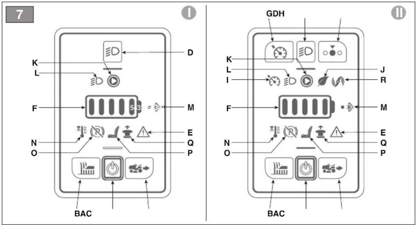
6.8.1 Pushbutton panel (type "I") fig. 7

Machine start button
With the key fully inserted (fig. 6.A), this button (fig. 7.A) turns the machine ON and enables all functions. Activation is signalled by an audible "beep".
NOTE
If all safety conditions are met, the "READY" icon comes ON (fig. 7.K) and the machine is ready to be used (see par. 7.4).

Cutting means engage and disengage pushbutton
Press the button fig. 7.B to engage/disengage the cutting means.
- When the cutting means are engaged, they become operational after a few seconds.
- When the cutting means are disengaged, a brake is applied simultaneously to stop them rotating after a few seconds.
NOTE
If the cutting means are engaged without taking the necessary safety precautions, the machine shuts down and cannot be restarted (see par. 7.2.2)
Reverse gear cutting enable button
Holding down the button fig. 7.C gives consent for reverse mowing.
For reverse cutting, engage the cutting means and simultaneously hold down the button.
NOTE
A single buzzer signal indicates the lack of consent for reverse cutting.

Beacon ON button
Pressing the button fig. 7.D turns the LED beacon on/off. When the beacon is ON, icon fig. 7.L is illuminated

Attention icon
If icon fig. 7.E is illuminated, it this indicates failure to comply with safety conditions or a possible malfunction of the machine (see chap. 15).

Battery LED
The LEDs fig. 7.F generally indicate the charge level of the machine's batteries but in particular combinations their lighting status provides information about machine malfunctions (see chap. 15).

"Ready" icon
The icon in fig. 7.K is illuminated when the machine is ON and ready to be used.

"Bluetooth" icon
The icon in fig. 7.M is illuminated when the machine and the data exchange device are connected.

Controller and/or motor over-temperature icon
The icon in fig. 7.N indicates overheating of electrical components. See chap. 15.

Transmission engagement / disengagement lever icon
The icon in fig. 7.O is illuminated when the transmission is not engaged (see par. 6.3 and chap. 15).

Operator on-board icon
The icon in fig. 7.P is illuminated when operator leaves the driving seat (see par. 7.2.2).

Emergency pushbutton icon
The icon in fig. 7.Q is illuminated if the emergency button is activated (see par. 6.5).
6.8.2 Pushbutton panel (type "II") fig. 7

Machine start button
With the key fully inserted (fig. 6.A), this button (fig. 7.A) turns the machine ON and enables all functions. Activation is signalled by an audible "beep".
NOTE
If all safety conditions are met, the "READY" icon comes ON (fig. 7.K) and the machine is ready to be used (see chap. 7.4).

Cutting means engage and disengage pushbutton
Press the button fig. 7.B to engage/disengage the cutting means.
- When the cutting means are engaged, they become operational after a few seconds.
- When the cutting means are disengaged, a brake is applied simultaneously to stop them rotating after a few seconds.
NOTE
If the cutting means are engaged without taking the necessary safety precautions, the machine shuts down and cannot be restarted (see par. 7.2.2)
Reverse gear cutting enable button
Holding down the button fig. 7.C gives consent for reverse mowing.
For reverse cutting, engage the cutting means and simultaneously hold down the button.
NOTE
A single buzzer signal indicates the lack of consent for reverse cutting.

Beacon ON button
Pressing the button fig. 7.D turns the LED beacon on/off. When the beacon is ON, icon fig. 7.L is illuminated

"CRUISE CONTROL" button
Pressing the button in fig. 7.G activates/deactivates the "CRUISE CONTROL" function. The Cruise Control command is used to maintain the desired speed in forward gear without having to keep the drive pedal pressed.
- By pressing the “CRUISE CONTROL” button (Fig. 7.G) while moving forwards, the machine will maintain the speed reached at that moment, without the driver having to act on the drive pedal (Fig. 6.F). When the function is active, the icon in fig. 7.I. is illuminated
NOTE
The "CRUISE CONTROL" function cannot be activated in reverse gear.
NOTE
Speeds may vary with respect to the selected values when the machine is moving up or down slopes.
To disengage the device and reset speed control using the drive pedal (fig. 6.F) simply:
- press the button fig. 7.G. or
- press the drive pedal (fig. 6.F).
ECO
Cutting means operating speed selector button
This button (fig. 7.H) is used to select 3 different cutting means rotation speeds.
- ECO: The cutting means rotation speed is reduced to extend the battery life. When this function is selected, the "leaf" icon is illuminated (fig. 7.J).

ATTENTION
It is not recommended to use this function in heavy grass cutting conditions (cutting of dense, high, humid grass).
- NORMAL: standard mower rotation speed for use in normal mowing conditions
- TURBO: The rotation speed of the cutting means is increased to cut grass in more difficult conditions (dense, tall, wet grass). When this function is selected, the "rotary blade" icon is illuminated (fig. 7.R). Battery life is reduced.

Attention icon
If icon fig. 7.E is illuminated, it this indicates failure to comply with safety conditions or a possible malfunction of the machine (see chap. 15).

Battery LED
The LEDs fig. 7.F generally indicate the charge level of the machine's batteries but in particular combinations their lighting status provides information about machine malfunctions (see chap. 15).

"Ready" icon
The icon in fig. 7.K is illuminated when the machine is ON and ready to be used.

"Bluetooth" icon
The icon in fig. 7.M is illuminated when the machine and the data exchange device are connected.

Controller and/or motor over-temperature icon
The icon in fig. 7.N indicates overheating of electrical components. See chap. 15.

Transmission engagement / disengagement lever icon
The icon in fig. 7.O is illuminated when the transmission is not engaged (see par. 6.3 and chap. 15).

Operator on-board icon
The icon in fig. 7.P is illuminated when operator leaves the driving seat (see par. 7.2.2).

Emergency pushbutton icon
The icon in fig. 7.Q is illuminated if the emergency button is activated (see par. 6.5).

ECO icon
The icon in fig. 7.J is illuminated when the ECO mowing mode is selected.

TURBO icon
The icon in fig. 7.J is illuminated when the TURBO mowing mode is selected.
6.9 BLUETOOTH FUNCTION
The Bluetooth function provides short-distance direct wireless connection between the machine and another device. The specific data exchange App must be installed on the device:
- download the App using the QR Code shown in fig. 37.
- follow the instructions.

The bluetooth connection is activated automatically when the machine is started and successful connection with the device is confirmed when the icon in fig. 7.M is illuminated.
Make sure that the connection with the device/App is active.
7. USING THE MACHINE
WARNING
The safety regulations to be followed are described in chapter 2. Strictly comply with these instructions to avoid serious risks or hazards.
7.1 PRELIMINARY OPERATIONS
Before starting to mow, it is necessary to carry out several checks and operations to ensure you can work efficiently and in maximum safety.
7.1.1 Battery check
Charge the batteries fully before using the machine for the first time after purchase (chap. 8.2.2).
Always check the battery charge status before using the machine (Fig. 7.F).
7.1.2 Seat adjustment
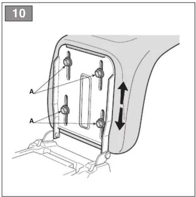
To change the position of the seat, loosen the four fixing screws (fig. 10.A) and slide the seat along the slots on the support. When the required position is found, fully tighten the four screws (fig. 10.A).
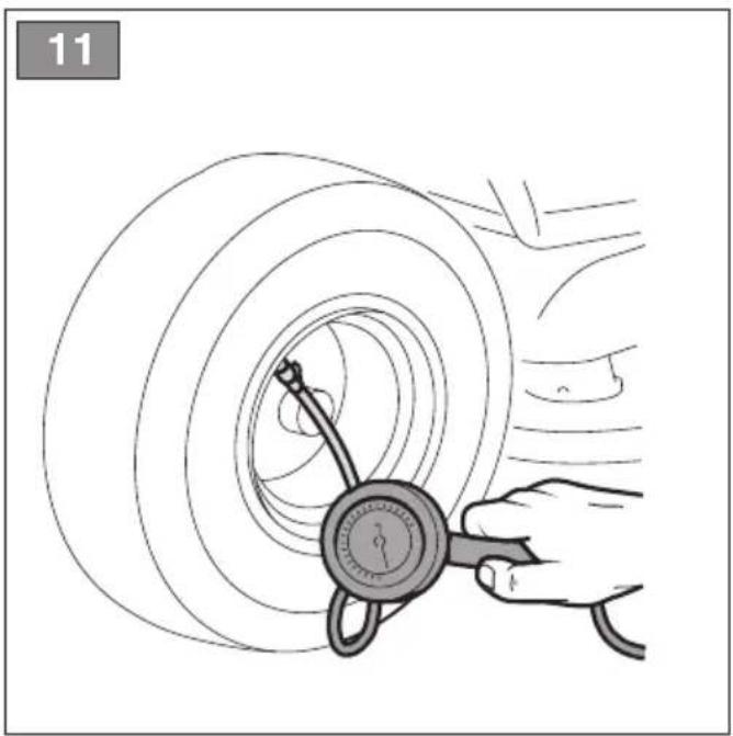
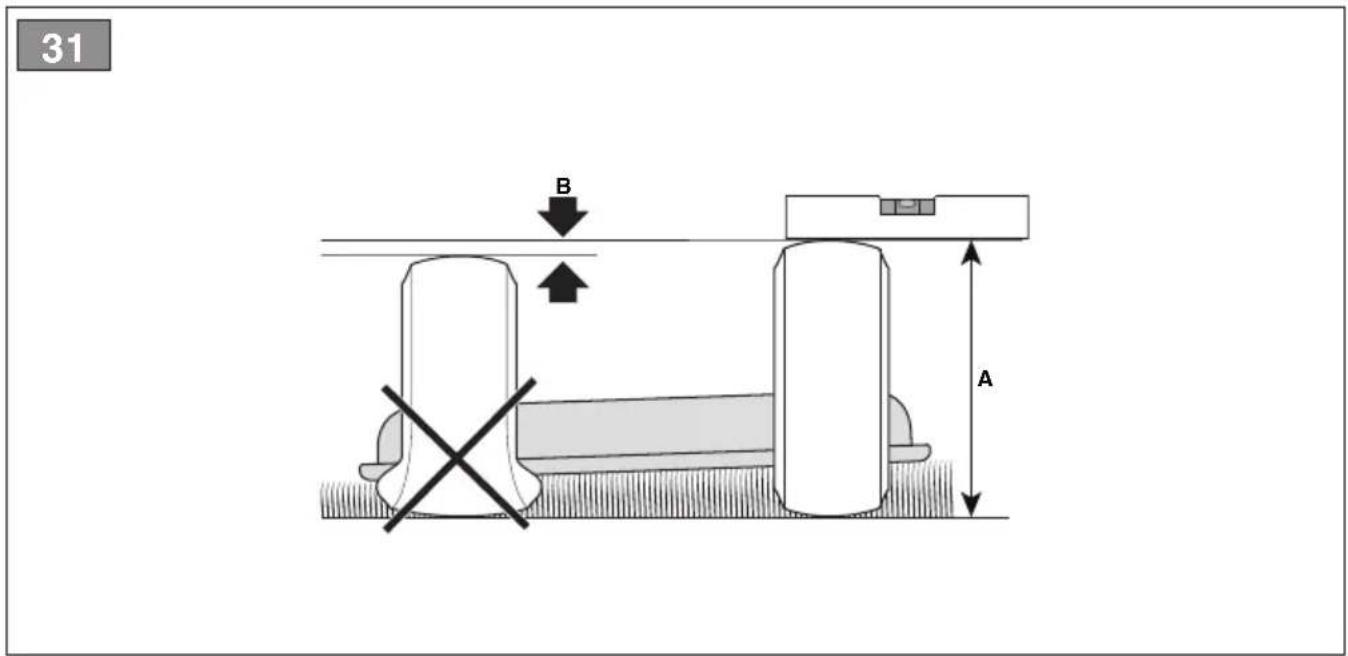
7.1.3 Tyre pressure
Having the right tyre pressure is the main condition for ensuring that the cutting means assembly is horizontal and mows evenly.
- Unscrew the protective caps
- Connect a compressed air line with a gauge to the valves (fig. 11)
- Adjust the pressure according to the values indicated in the "Technical Data" chart.
7.1.4 Preparing the machine before starting work
NOTE
This machine can be used to mow lawns in a number of different ways; before starting, prepare the machine based on how the lawn is to be mowed.
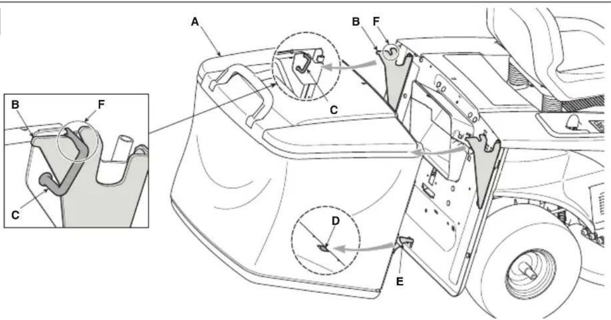
a. Pre-set for cutting and collecting grass in the grass catcher
Hook the grass catcher bag (fig. 9.A) by inserting the two attachments (fig. 9.C) into the slots (fig. 9.F) in the two supports (fig. 9.B).
Make sure that the grass catcher frame (fig. 9.D) hooks on to the stop pawl (fig. 9.E).
b. Pre-set for cutting and rear unloading of grass to ground
If you want to work without the grass catcher, a rear unload protection kit is available on request (optional, par.16.3) which must be mounted on the rear plate as indicated in the pertinent instructions.
c. Pre-set for cutting and chopping grass If you decide to mow grass, mulch it and leave it on the lawn, a "mulching" kit is available upon request (chap.
16.1). This has to be attached to the rear plate as indicated in the instructions.
7.2 SAFETY CHECKS
Run the following safety checks and ensure that the results correspond to those outlined in the tables.

SAFETY INSTRUCTION
Always perform safety checks before use.
7.2.1 General safety check
| Object Result | |
| Batteries. No damage to | casing and cover. |
| Pushbutton panel controls and commands | Good condition.No damage. |
| Rear unload guard, grass catcher. | Good condition. No damage. Properly installed. |
| Electrical cables All insulation intact. | No mechanical damage. |
| Operate the machine forwards/reverse and release the drive pedal. | The machine slows down and stops. |
| Safety devices Proceed as indicated in par. 7.2.2 | |
7.2.2 Control of safety devices
The safety devices work in two ways:
A. To prevent the machine from starting if all the safety requirements have not been met;
B. To stop the machine if even just one of the safety requirements is lacking.
| Status Action Result | ||
| operator seated.Drive pedal in neutral position (pedal released).Emergency button deactivated. | Fully insert the key the machine is ready to be turned ON. | |
| Machine on or in operation. | The operator stands up from the seat. | All services are deactivated. The icon in fig. 7.E icon flashes and the icon in fig. 7.P is illuminated. |
| operator seated.Drive pedal in forward or reverse position. | Try to start the machine. | The icons in fig. 7.E and fig. 7.O remain ON, battery LEDs 1, 2, 4 and 5 flash.  |
Emergency button activated. Attempt to start the machine. The machine switches ON. The icon in fig. 7.E flashes and the icon in fig. 7.O is illuminated.Drive and cutting means do not work. | ||
| Cutting means engaged. Reverse is activated without holding down the reverse mowing consent button. | The cutting means disengage. | |
| Cutting means engaged. Lift the grass catcher or remove the rear discharge guard (for rear collection models only) | The cutting means disengage. | |
| Machine ON and Operating. Release the drive pedal. The machine slows down and stops. | ||
| Machine ON and Operating. Test drive. No unusual vibrations, no unusual | sound, correct operation of the steering, controls and pedals. | |

DANGER
If any results do not to match the indications in the tables, do not use the machine! Contact an Authorised Service Centre to have it checked and repaired if necessary.
NOTE
Always bear in mind that the safety devices prevent the machine from starting if safety requirements have not been met. In such cases, once start-up consent has been reset, remove the key before starting the machine again.
7.3 USING ON SLOPES
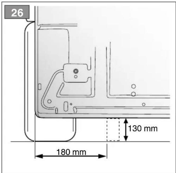
Comply with the limits indicated in the "Technical Data" Tables as in "fig. 12" regardless of the mowing direction.
Remember there is no such thing as a "safe" slope. Driving on grass slopes requires particular care. To prevent overturning or loss of control over the machine:
- Never mow across the face of the slope. Lawns on slopes must be mowed by moving up and down and never across them in forward gear. When changing direction, take great care that the wheels facing the slope do not hit any obstacles (such as stones, branches, roots, etc.) that may cause the machine to slide sideways, tip over or make you lose control.
- Do not stop or start suddenly when going up or downhill;
- Shift to drive gear very gently paying particular attention to prevent the machine from tipping up.
- Reduce speed:
• before changing direction and during tight turns - before tackling a slope, especially downhill, to ensure a safe braking distance.
- Never switch to reverse gear to decrease speed when going downhill: this could cause loss of control of the machine, especially on slippery ground.

NOTICE
Reduce forward speed if the machine is moving on a slope.
7.4 START-UP
To start the machine:
- Check that the transmission is engaged (par. 6.3).
- Sit in the operator's position.
- Fully insert the key (fig. 6.A).
- Wait for the machine's electrical check to be performed, during which the icons on the pushbutton panel will flash.
- Press the power button (Fig. 7.A).
- Wait until the "Ready" icon (fig. 7.K) is ON steady.
NOTE
At the end of the electrical check, the LED comes ON momentarily.
7.5 OPERATION
7.5.1 Drive and transfers
When moving the machine:
- disengage the cutting means (par. 6.8, fig. 7.B);
- bring the cutting means assembly to the highest position;
- Press the drive pedal to move the machine in the required direction of driving and set the required speed by adjusting the pressure on the pedal.
- Go to the work area.

DANGER
Drive must be engaged in accordance with the modes described (paragraph 6.2) to avoid sudden meshing, jerking start and loss of control of the vehicle, especially on slopes.
NOTE
Reverse must only be engaged when the machine has stopped.
7.5.2 Grass cutting
- Set the cutting means assembly to the work position (par. 6.4).
- Engage the cutting means (par. 6.8, fig. 7 B) only on lawns; do not engage them on stony ground or when the grass is very high.
- When starting to cut grass, start off slowly and carefully.
- Adjust work speed (para 6.2) and cutting height (par. 6.4) in relation to lawn conditions (height, density and humidity of the grass) and the amount of grass to be cut.

NOTICE
The forward work speed decreases if the battery charge threshold falls below 40% (par. 8.2.2).
NOTE
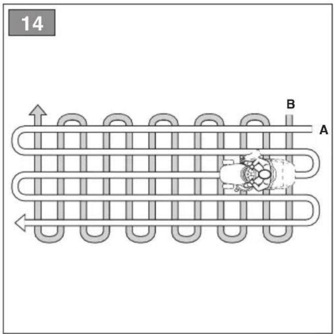
The appearance of the lawn will improve if you alternate cutting in both directions at the same height (Fig.14.A.B).
NOTE
To proceed in reverse gear with the cutting means engaged, press and hold the consent button (fig 7.C) so that the motor does not stop.
Disengage the cutting means and move the cutting means assembly to the highest position:(par. 6.4):
- When moving between work areas
- When driving on grass free surfaces
- Every time it is necessary to overcome an obstacle.
7.5.3 Suggestions for maintaining a nice lawn
- To keep a lawn green and soft with a good appearance, it should be cut regularly. A lawn can be composed of different types of grass. If the lawn is cut frequently, grass and roots grow more vigorously, forming a solid grassy bed; if the lawn is cut is less frequently, higher grass and weeds start growing (clover and daisies, etc.).
- It is always better to cut the grass when dry.
- The cutting means must be in good condition and well sharpened so that the grass is cut straight without a ragged edge that leads to yellowing at the ends.
- The frequency of mowing should be in relation to the rate of growth of the grass, which should not be left to grow too much between one cut and the next.
- During hot and dry periods, the grass should be cut a little higher to prevent the ground from drying out.
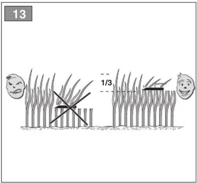
- The best height of the grass on a well-kept lawn is approx. 4-5 cm and with one mowing, you do not need to remove more than one third of the total height. If the grass is very tall, it should be cut twice in a twenty-four hour period; the first cut with the cutting means at the maximum height and then if necessary at a lower height, and the second at the desired height (fig. 13).
- The lawn will have a better appearance if the cuts are made by alternating them in both directions (fig. 14).
- If the discharge chute tends to get blocked with grass, you should reduce the forward speed as it may be too high for the condition of the grass. If the problem persists, the
probable causes are either badly sharpened cutting means or deformed fins.
- Be very careful when mowing near bushes or kerbs as these could distort the horizontal position of the cutting means assembly and damage its edge as well as the cutting means.
7.5.4 Grass catcher emptying
NOTE
The grass catcher can only be emptied with the cutting means disengaged, otherwise the engine stops.
NOTE
Do not let the grass catcher become too full as this may block the discharge chute.
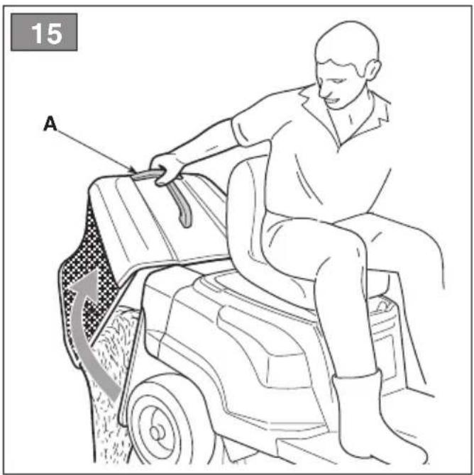
A continuous buzzer indicates when the grass catcher is full: Proceed as follows:
- disengage the cutting means (par. 6.8, fig. 7.B) and the signal is interrupted;
- stop the machine;
- take hold of the rear lever (fig. 15.A) and tip the grass catcher bag up to empty it;
- close the grass catcher again so that it remains coupled to the pawl (fig. 9.B).
7.5.5 Cleaning the unload chute
Cutting very tall or wet grass, particularly at excessively high speed, can clog up the discharge chute. If it clogs, follow the instructions provided in chap. 8.3.2.
7.5.6 Mowing completed
When mowing has been completed:
- disengage the cutting means;
- turn around with the cutting means assembly in its highest position. (par. 6.4)
7.6 STOP
To stop the machine:
- Release the drive pedal to stop the drive gear.
- Turn the machine OFF by removing the key (fig. 6.A).
NOTE
To save battery power, do not leave the key inserted when the machine is not in use.
7.7 AFTER USE
- Allow the machine to cool before storing it in an enclosed space.
- Clean (par. 8.3).
- Make sure there are no loose or damaged components. If necessary, replace the damaged components and tighten any screws and loose bolts or contact the authorised service centre.
- Position the machine near to a power socket and charge the batteries *(par. 8.2.2) so that it is ready to be used when next required. Alternatively, take the batteries out of their housing and charge them with the external battery charger (optional).
Whenever the machine is left unattended, the operator leaves the driving seat or parks the machine:
- Stop the machine;
- bring the cutting means assembly to the lowest height position;
- make sure that all moving parts have come to a complete stop;
- Remove the ignition key (fig. 6.A);
ATTENTION
Always leave the machine in a shaded area or sheltered environment at a temperature below +35 °C
8. ROUTINE MAINTENANCE
8.1 GENERAL INFORMATION
DANGER
The safety regulations to be followed are described in chapter 2. Strictly comply with these instructions to avoid serious risks or hazards.
Before commencing any inspections, cleaning or maintenance/adjustments on the machine:
- disengage the cutting means;
- stop the machine;
- make sure that all moving parts have come to a complete stop;
- remove the key (fig. 6.A);
DANGER
Never leave the key inserted or within reach of children or inappropriate people.
- read the relevant instructions;
- use suitable clothing, protective gloves and goggles
The frequency and type of procedures are outlined in the "Maintenance table". The table will help you maintain your machine's safety and performance. It summarises the main interventions to be made and the frequency applicable to each of them. Carry out the relevant task as soon as it is scheduled to be performed. The use of non-genuine and/or incorrectly assembled spare parts and attachments could adversely affect machine operation and safety. The manufacturer shall decline all liability in the event of injuries or damages caused by such parts. Genuine spare parts are supplied by Authorised Assistance Centres and Dealers.
8.2 BATTERY
8.2.1 Battery life
Battery life (and therefore the area of lawn that can be mowed before recharging) is essentially affected by:
A. Work factors involving higher energy requirement (e.g. cutting with dense, tall, humid grass).
B. Operator behaviour that should be avoided:
- switching the machine on and off frequently whilst working;
- Setting a cutting height that is too low for the lawn conditions;
- Working at a speed that is too high for the amount of grass to be removed.
C. Environmental factors, such as a high ambient temperature, above +35 °C.
To optimize the life of the batteries, it is always advisable to:
- Cut the grass when the lawn is dry;
- Cut the grass frequently so that it doesn't grow too tall;
-
Set a higher cutting height when the grass is very tall, then set a lower height and cut the lawn again;
-
Do not use the machine in "mulching" mode (if available) with very tall grass.
- cut the grass at a temperature between +5 and +35 °C;
- use the "Eco" function (fig. 7II-H, par. 6.8.2).
8.2.2 Battery charging
The machine battery must always be charged:
- Before using the machine for the first time after purchase;
- When the minimum state of charge is reached (Fig. 7 F).
- Before any prolonged period when the machine is not in use
- Every two months during storage.
- before starting up the machine after a prolonged period of inactivity.
ATTENTION
When the battery is not connected to the mains network with the specific battery charger, battery charge will be lost even if the battery is not used. If the battery is subject to a deep discharge, it could be seriously damaged to the point that it can no longer be used. The warranty does not cover damage caused by batteries not charged at regular intervals.
ATTENTION
Recharging must take place exclusively using the battery charger (fig. 17.A) or alternatively through the external battery charger (fig. 36.B). Other recharging systems can irreversibly damage the batteries.
ATTENTION
The batteries must only be charged in an area protected against poor weather conditions, in the shade, at a recommended temperature of between +0 e +35 °C.
The batteries are equipped with a protection device that inhibits recharging if the environmental temperature is not between 0 and +45°C.
NOTE
The battery can be charged at any time, even partially, with no risk of damaging it.
SAFETY INSTRUCTION
Do not carry out maintenance or cleaning operations while the battery is charging.
a. Charging the battery on-board
To charge the battery:
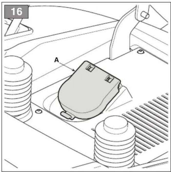
- Position the machine close to a power outlet and remove the key (fig. 6.A);
- Lift the seat;
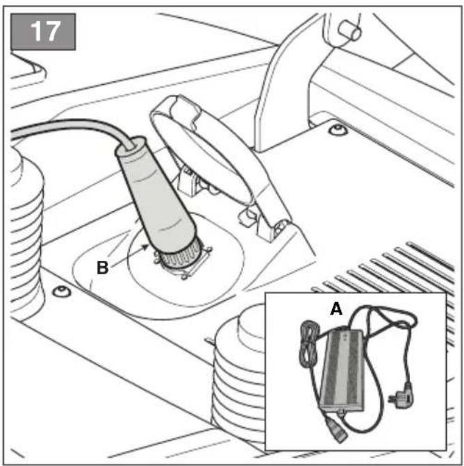
- Life the cap on the recharging socket (fig. 16.A);
- Connect the battery charger supplied to the recharging socket (fig. 17.A) with the specific bayonet mount for the respective connector (fig. 17.B);
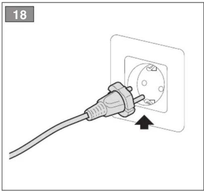
- Connect the battery charger to the mains by inserting its plug (fig. 18).
To charge the battery, a socket with a differential safety switch (Fig. 19.A) is supplied (where required) to which the charge cable (Fig. 19 E) must be connected.
The socket with the differential safety switch must be connected to the mains power network and an operating test must be carried out:
- Press the "RESET" button (Fig. 19 BA) to activate operation. The indicator light must be "ON" (Fig. 19.C).
- Press the "TEST" button (Fig. 19.D) to perform the operating test. The indicator light must be "OFF" (Fig. 19.C).

DANGER
If the operating test is not completed successfully, the socket with the differential switch must not be used. If the operating test is completed successfully, it can be used and the operator can proceed with the charging stage.
During recharging, the battery indicator LEDs (fig. 7.F) flash progressively. When each individual charge threshold is reached, the respective LED remains lit steadily, while the others continue to flash.

ATTENTION
After 24 hours of operation, the on-board battery charger is deactivated and the batteries are not kept under charge indefinitely.

NOTICE
Installed batteries are charged in sequence. It is therefore advisable always to carry out a complete charging cycle.
b. Charging the battery off-board
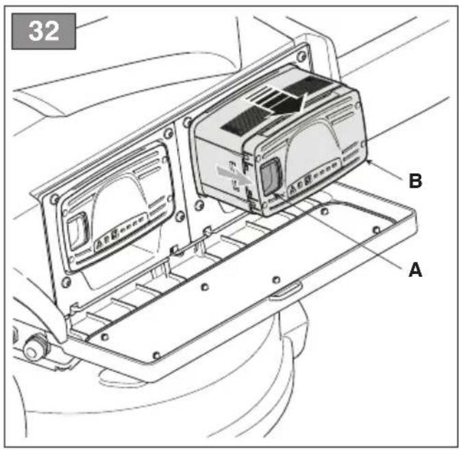
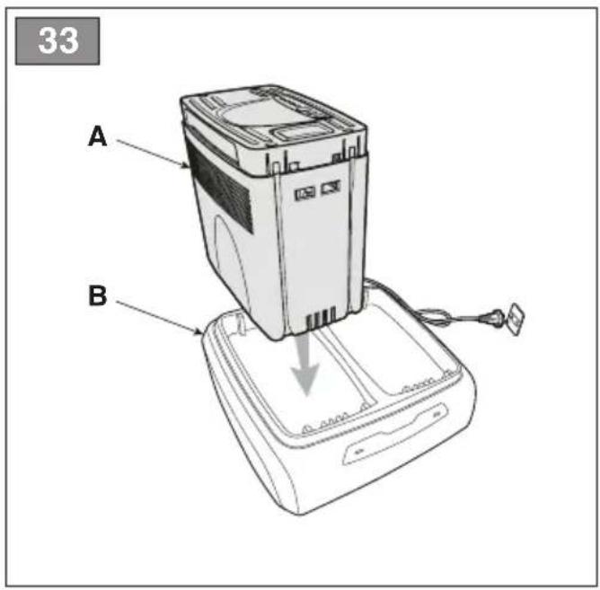
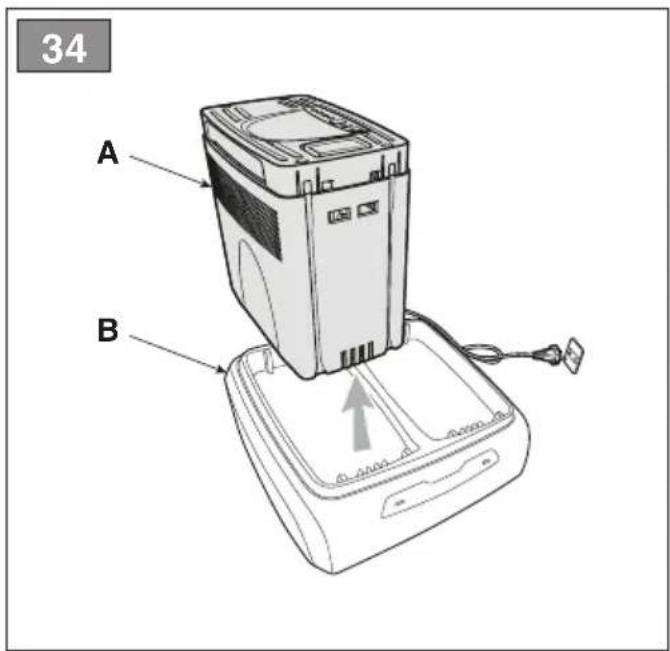
To charge the battery:
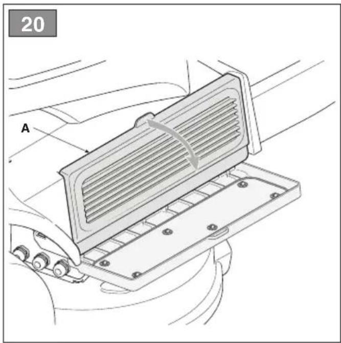
- Open the hatch (fig. 20.A) on the battery housing;
- Press the release button located on the battery (Fig. 32.A) and remove the battery (Fig. 32.B);
- Fit the battery (Fig. 33.A) in the battery charger compartment (Fig. 33.B);
- Connect the battery charger (Fig. 33.B) to a power socket with the voltage indicated on the rating plate;
- Fully charge the battery following to the instructions given in the battery charger manual.
- When charging is complete, remove the battery (Fig. 34.A) from the battery charger compartment (Fig. 34.B);
- Disconnect the battery charger (Fig. 34.B) from the electrical mains;
- Mount the battery (fig. 35.A) in its housing on the machine again and close the battery compartment hatch.
The batteries can be kept under charge indefinitely.
| Charge status (SOC) | Led ON |
| SOC > 80% | |
| 60% ≤ SOC < 80% | 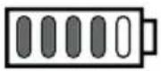 |
| 40% ≤ SOC < 60% | 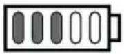 |
| 20% ≤ SOC < 40% | 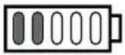 |
| 10% ≤ SOC < 20% | 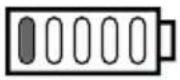 |

NOTICE
Battery charging times may increase if the machine has been used in heavy-duty work conditions with consequent indication of battery overheating (chap. 15).

NOTICE
If a battery becomes completely discharged, the signalling LEDs remain off until the minimum charge threshold is reached.
NOTE
When the charge level drops below the 10% threshold, the first battery LED begins flashing. Below the 4% threshold, the first battery LED begins flashing rapidly and the cutting means disengage. Stop mowing and return to base to recharge the batteries.
When charging is complete, the charging system turns off after 24 hours and there is no automatic maintenance and recharging of the battery charge.

NOTICE
If, when the battery charger is connected to the tractor, the 5 LEDs fig. 7.F all flash at the same time, it means charging is not in progress. Check the battery charger/mains connection.
NOTE
While charging, all machine functions are disabled, even when the key is fully inserted.

ATTENTION
The batteries mounted on the machine are designed and manufactured for this type of use. Inasmuch: :
- DO NOT replace the batteries with other non-
original batteries;
- DO NOT carry out interventions unless they have been indicated in this manual. In the event of any problems with the batteries, contact your Dealer.
8.3 CLEANING
Clean thoroughly following the instructions below every time it is used.
8.3.1 Cleaning the machine
- Clean the outside of the machine washing the plastic parts of the bodywork with a damp sponge using water and detergent, taking care not to wet the electric motors, the batteries or the parts of the electrical system.
- To reduce the risk of fire, keep the motors and battery housings free of grass, leaves residues or excessive grease.
- Keep the pushbutton panel free of dirt and debris.

ATTENTION
Never use high pressure water or aggressive fluids to wash the bodywork and electric motors.
8.3.2 Cleaning the unload chute
If the discharge chute is clogged:
- remove the grass catcher or the rear discharge guard;
- remove the grass cuttings; you can reach them from the chute discharge opening.
8.3.3 Cleaning the grass catcher
- Empty the grass catcher.
- Shake it to remove grass cuttings and soil residue.
- Replace the grass catcher and clean the interior of the cutting means assembly (par. 8.3.4-a), now remove the grass catcher, empty and rinse it, then place it where it can dry quickly.
8.3.4 Cleaning the cutting means assembly
Clean cutting means assembly thoroughly to remove any grass residue or debris.

WARNING
Keep people or animals away from the surrounding area when cleaning the cutting means assembly.
a. Cleaning the interiors

ATTENTION
Washing the inside of the cutting means assembly and the unloading chute must be performed with the grass catcher mounted and the mulching cap inserted (if present) or with the rear unload guard mounted.
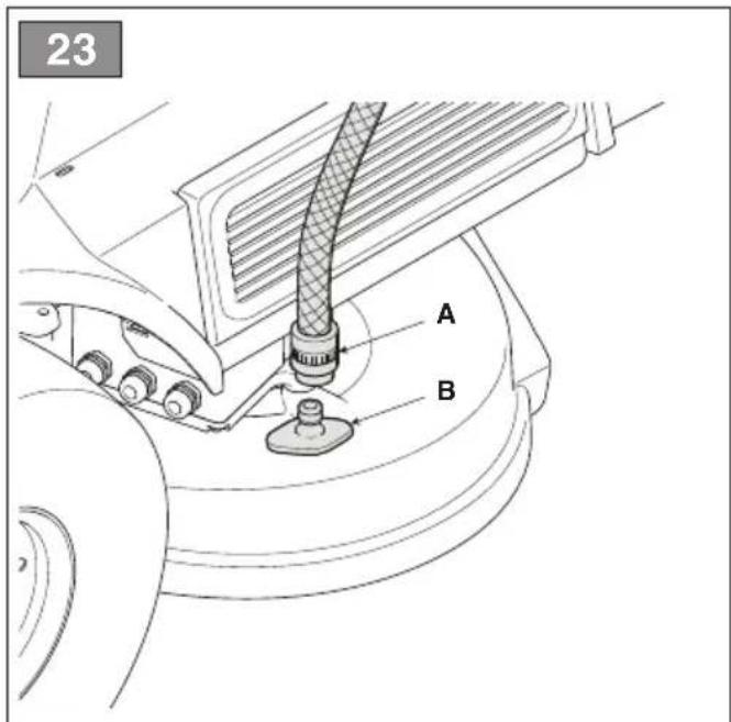
- Place the machine on a flat, solid surface.
- Connect a water hose (fig. 23.A) to one of the two specific couplings (fig 23.B) and open the water supply.
- Sit in the driving seat and start the machine.
- Fully lower the cutting means and engage the cutting means.
- Let the water flow for a few minutes and then stop the machine.
- Turn off the water supply and disconnect the hose from the coupling.
- Repeat the procedure on the other coupling.
b. Cleaning the exterior

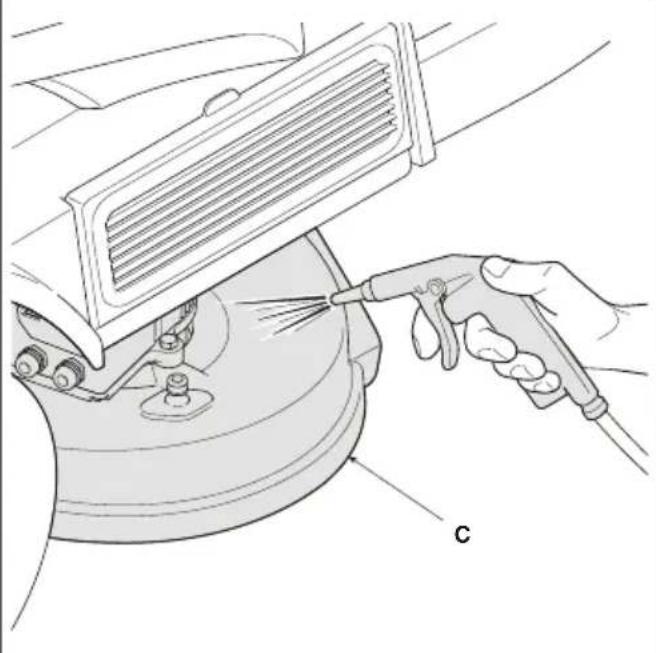
SAFETY INSTRUCTION
Do not allow debris and dried grass to accumulate in the upper part of the cutting means assembly in order to maintain maximum machine efficiency and safety levels.
To clean the upper part of the cutting means assembly:
- fully lower the cutting means assembly;
- blow a jet of compressed air over the upper part of the assembly (fig. 23.C).
8.3.5 Cleaning the battery ventilation filters
Clean the battery ventilation filters every year as described below:
- Open the hatch (fig. 20.A) on the battery housing;
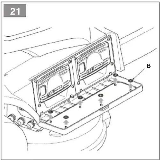
- Remove the mounting rings (fig. 21.B) from the ventilation filter.
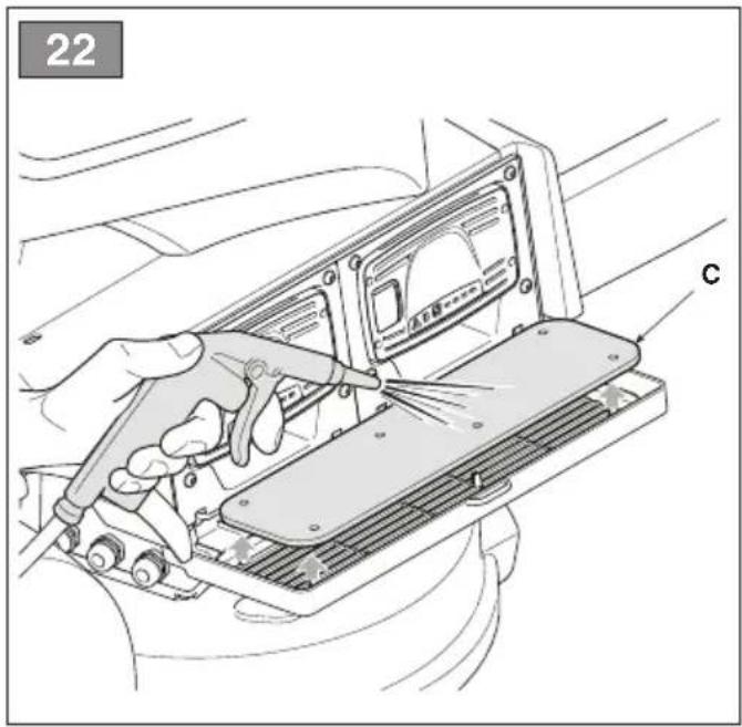
- Remove the ventilation filter (fig. 22.C) through the hatch on the battery compartment and clean it with compressed air.
- Then replace filter through the hatch, securing it with the specific mounting rings.
NOTE
Perform the operations on both sides of the machine.
8.4 LUBRICATION
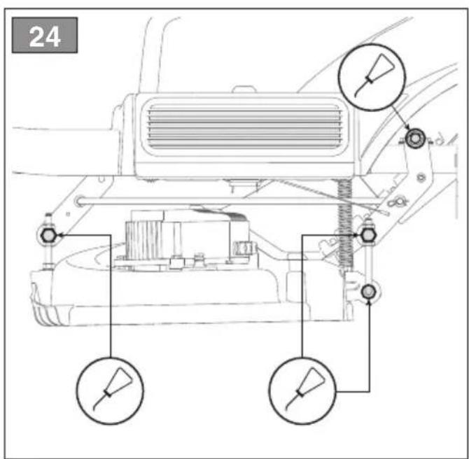
| Object Action | |
| Cutting means assembly | Lubricate the lifting points with oil (fig. 24). |
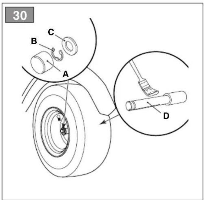
| Wheel axles Remove the wheels. Lubricate the axles with grease (Fig. 30.E). | |
8.5 NUTS AND BOLTS
- Keep all nuts, bolts and screws tight to be sure the equipment is in safe working condition.
9. OCCASIONAL MAINTENANCE
9.1 SAFETY RECOMMENDATIONS

SAFETY INSTRUCTION
You must immediately contact your Authorised Service Centre or Dealer if the following malfunctions are found:
- the neutral position of the drive pedal (service brake)
- cutting means engage and disengage functions
- switching the drive to forward or reverse gears.
9.2 CUTTING MEANS ASSEMBLY / CUTTING MEANS
9.2.1 Aligning the cutting means assembly
The cutting means assembly should be correctly adjusted to obtain an evenly mown lawn (fig. 1). If mowing is uneven, check the tyre pressure (par. 7.1.3). If this is not sufficient to achieve an even cut, please contact your Dealer to adjust the alignment of the cutting means assembly.
9.2.2 Cutting means
Badly sharpened cutting means pull at the grass and cause the lawn to turn yellow.

SAFETY INSTRUCTION
Always replace damaged, bent or worn pairs of cutting means, together with their nuts and bolts, in order to maintain their balance.

WARNING
All work on the cutting means (disassembly, sharpening, balancing, repairing, reassembly and/or replacing) are demanding jobs that require special skills as well as special tools; For safety reasons, these jobs are best carried out at a Authorised Service Centre.

ATTENTION
Always use original cutting means bearing the code indicated in the "Technical Data".
NOTE
Given product evolution, the cutting means listed in the "Technical Data" table may be replaced in time with others having similar interchangeable and operating safety features.
9.3 REPLACING FRONT / REAR WHEELS
9.3.1 Preliminary operations

DANGER
Use a suitable lifting device.
Before changing the wheels it is necessary to complete some preliminary operations:
- Position the machine on a solid and even surface that guarantees stability of the machine.
- Stop the machine;
- Remove the key from the ignition;
- Position the lifting device in the lifting position near the wheel to be changed (par. 9.3.2; par. 9.3.3).
- Check that the lifting device is perfectly perpendicular to the ground.
9.3.2 Choice and positioning of the jack on the rear wheels
- Position some wooden wedges (fig. 25.A) at the base of the wheel (fig. 25.B) next to the wheel to be changed (fig. 25.C).
- The maximum possible jack height when closed is 130 mm. (fig. 26).
- Position the jack under the rear plate (fig. 27.A) at 180 mm from the side edge (fig. 26).
NOTE
In this position the jack allows you to raise only the wheel to be changed.
9.3.3 Choice and positioning of the jack on the front wheels
- Position some wooden wedges (fig. 28.A) at the base of the wheel (fig. 28.B) behind the wheel to be changed (fig. 28.C).
- The maximum possible jack height when closed is 170 mm.
- Place on top of the jack (fig. 29.A) a squared piece of wood (fig. 29.B) having a cross-section of about 5 x 2 cm.

ATTENTION
The thickness of the wood prevents damage to the front axle.
- During this stage, keep the wooden pad balanced on the jack with one hand. Lift the jack making sure that the wooden pad rests against the frame and the structural parts (fig. 29.C).
NOTE
The jack positioned in this way makes it possible to lift the entire front axle.
9.3.4 Changing the wheel

SAFETY INSTRUCTION
Make sure that the machine remains still and stable during the lifting process. If you notice anything out of the ordinary, lower the jack immediately, check and resolve any problems and lift the machine again.
- Remove the cover (fig. 30.A).
- Raise it enough to extract the wheel easily.
- Use a screwdriver to remove the snap ring (fig. 30.B) and the shoulder washer (fig. 30.C).
- Remove the wheel to be changed.
- Smear the axle (fig. 30.D) with grease.
- Mount the spare wheel.
- Carefully replace the shoulder washer and snap ring.
NOTE
Check that the two rear wheels are the same height (fig. 31.A) and that the difference between the external diameters of the two wheels (fig. 31.B) is no greater than 8-10 mm. On the contrary, to avoid uneven mowing, the cutting means assembly must be aligned by an Authorised Service Centre.
9.3.5 Repairing or changing tyres
The tyres are “Tubeless” and so all punctures must be repaired by a tyre repairer following the procedures required for this type of tyre.
9.4 REPLACING LED LAMPS
If the LED beacon fails, contact an Authorized Service Centre.
10. STORAGE
When you intend to put your machine away for more than 30 days:
- Remove the ignition key.
- Clean the machine thoroughly.
-
Check the machine for any damage. If necessary, contact the authorised service centre.
-
Store the machine:
• with the cutting means assembly lowered
- in a dry place;
- protected against poor weather conditions, at a recommended temperature of between 0 and +40 °C.
• covered with a sheet if possible;
• in a place out of children's reach;
- making sure that keys or tools used for maintenance are removed.
ATTENTION
Make sure that the battery is fully charged at least once a month and always before use.
When re-starting the machine, set it up as indicated in chapter "7. "Using the machine".
11. HANDLING AND TRANSPORT
- When handling the machine, always:
- disengage the cutting means;
- bring the cutting means assembly to the highest position;
- switch off the machine and remove the ignition key
-
disengage the drive (par.6.3).
-
When transporting the machine on a vehicle or trailer, always:
- use an access ramp of suitable strength, width and length;
-
load the machine with the electric motor switched off, with the key removed from the ignition, without a driver and pushed by an adequate number of people;
-
lower the cutting -device assembly;
- position it so that it does not cause a hazard to anyone;
• engage the drive (par.6.3). - lock it firmly on the means of transport using ropes or chains to prevent it from tipping over and possible damage.
SAFETY INSTRUCTION
If you feel unable to carry out handling or transport in safe conditions, contact the Service Centre.
12. ASSISTANCE AND REPAIRS
This manual provides all the necessary information to run the machine and for correct basic maintenance operations which can be performed by the user. Any regulations and maintenance operations not described herein must be carried out by your Dealer or Authorised Service Centre, which have the necessary knowledge and equipment to ensure that the work is carried out correctly, maintaining the correct degree of safety and the original operating conditions of the machine. Any operations performed in unauthorised centres or by unqualified persons will totally invalidate the warranty and all obligations and responsibilities of the manufacturer.
- Only Authorised Service Centres can carry out guaranteed repairs and maintenance.
- The Authorised Service Centres only use genuine spare parts. Genuine spare parts and attachments have been designed specifically for machines.
- Non-original parts and attachments are not approved; use of non-original spare parts and attachments will jeopardise the safety of the machine and relieve the Manufacturer from all obligations or liabilities.
- It is advisable to send your machine once a year to an Authorised Service Centre for servicing, assistance and safety device inspection.
13. WARRANTY COVERAGE
The warranty conditions are intended for consumers only, i.e. non-professional operators. The warranty covers all material quality and manufacturing defects recognised during the warranty period by your Dealer or Authorised Service Centre. The warranty is restricted to the repair or replacement of components recognised as faulty.
The warranty only applies to machines subjected to regular maintenance. The user must follow all the instructions provided in the accompanying documentation. The warranty does not cover damages resulting from:
- Failure to become familiar with the documentation accompanying the machine (Instruction manual).
• Professional use. - Carelessness, negligence.
- External causes (lightning, impact, presence of foreign bodies inside the machine) or incidents.
- Incorrect use or assembly or prohibited by the manufacturer.
- Poor maintenance.
- Modification to the machine.
- Use of non-genuine spare parts (adaptable parts).
- Use of attachments not supplied or not approved by the manufacturer.
The warranty does not cover:
- The routine/occasional maintenance operations (described in the owner's manual).
- Normal wear and tear of consum such as cutting means, wheels, beacons, safety bolts and wiring.
• Normal wear and tear. - Deterioration in the appearance of the machine due to use.
• Cutting means supports. - Any accessory expenses related to the enforcement of the warranty, such as costs incurred to travel to the user's location, transfer of the machine to the Dealer, rental of replacement equipment or calling of independent enterprises to perform maintenance work.
The user is protected by his or her own national legislation. The purchaser's rights under the national laws or his or her own country are not in any way restricted by this warranty.
14. MAINTENANCE TABLE
Use the boxes at the side to note the date or number of operating hours when the intervention was performed.
| Intervention Frequency | (hours) | Performed (Date or Time) Notes | |||||
| Check all fasteners | Before each use | ||||||
| Tyre pressure check | Before each use par. 7.1.3 | ||||||
| Safety checks/check controls | Before each use par. 7.2 | ||||||
| Check the drive release lever | Before each use par. 6.3 | ||||||
| Battery charge level | Before each use After each use Before storage | par. 8.2 | |||||
| General cleaning and inspection | After each use par. 8.3 | ||||||
| Checking for any damage to the machine. If necessary, contact the authorised service centre. | After each use | ||||||
| Cutting means positioning and sharpening check | 25 * | ||||||
| Replacing cutting means | 100 * | ||||||
| General lubrication | 25 par. 8.4 ** | ||||||
| Check/clean the battery ventilation filters | Annual para. 8.3.5 | ||||||
* This operation must be carried out by your Dealer or an Authorised Service Centre.
** General lubrication of all joints should also be carried out whenever the machine is to be left unused for a long period
15. TROUBLESHOOTING
| PROBLEM Cause Remedy | ||
| 1. The machine will not switch on. | Low battery. | Charge the battery (par. 8.2.2). |
| 2. The battery charger does not charge the batteries | Batteries not mounted correctly in the charger. | Make sure they are correctly inserted (fig. 33). |
| Unsuitable environmental conditions. | Recharge the battery in places with suitable temperatures (see battery/battery charger instruction manual). | |
| Dirty contacts. Clean the contacts. | ||
| No power supply to the battery charger . | Check it is plugged in and the power socket is energised. | |
| Faulty battery charger. Replace with an original spare part. | ||
| If the problem persists, refer to the battery charger manual. | ||
| 3. Irregular cutting | Cutting means sharpening is reduced. | Contact an Authorised Service Centre. |
| High forward speed in relation to the height of the grass to be cut.Cutting means assembly full of grass. | Reduce advancing speed and/or increase the cutting height.Wait for the grass to dry.Clean the cutting means assembly. | |
| 4. Unusual vibrations during use. | Cutting means incorrectly balanced.Cutting means loose.Loose parts.Possible damage | Contact an Authorised Service Centre for verifications, replacements or repairs. |
5. The icon in fig. 7.E remains ON and battery LEDs 2 and 5 flash.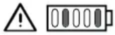 | Battery current overload caused by: | |
| 1. Work conditions too demanding. Reduce forward speed: | ||
| 2. Slope too steep . | Reduce the forward speed and check the slope of the ground where you are working. | |
6. The icon in fig. 7.N flashes.All the other indications in the push-button panel (icons/LEDs) remain functional and visible. | Pre-alarm for battery, drive motor and/or cutting means motor over-temperature because of: | |
| 1. Work conditions too demanding. Reduce forward speed: | ||
7. The icons in fig. 7.E and fig. 7.O remain ON, battery LEDs , 2, and 4 flash.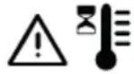 [0000] [0000] | Battery over/under temperature caused by: | Turn off the machine, wait for at least 5 minutes and then restart it. |
| 1. Work conditions too demanding. Reduce forward speed: | ||
8. The icon in fig. 7.E remains ON and battery LEDs 1, 4 and 5 flash. | Current overload to cutting means caused by: | |
| 1. Work conditions too demanding. Reduce forward speed: | ||
| 2. Obstructions that prevent rotation of the cutting means. | Remove the obstructions. | |
| 3. The cutting means assembly is full of grass | Clean the cutting means assembly: | |
9. The icons in fig. 7.E and fig. 7.O remain ON, battery LEDs 1 and 3 flash. | Cutting means motor over-temperature caused by: | Turn off the machine, wait for at least 5 minutes and then restart it. |
| Work conditions too demanding. Reduce forward speed: | ||
10. The icon in fig. 7.E remains ON and battery LEDs 1, 3 and 5 flash. | Cutting means motor stall caused by: | |
| 1. Work conditions too demanding. Reduce forward speed: | ||
| 2. Obstructions that prevent rotation of the cutting means. | Remove the obstructions. | |
| 3. The cutting means assembly is full of grass | Clean the cutting means assembly: | |
11. The icons in fig. 7.E and fig. 7.O remain ON, battery LEDs 1, 2 and 4 flash.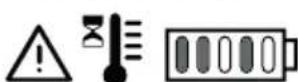 | Drive motor over-temperature caused by. | Switch off the machine and wait for at least 5 minutes before repeating the starting procedure. |
| 1. Drive motor under stress. Reduce forward speed: | ||
| 2. Slope too steep. | Reduce speed and check the slope of the ground where you are working. | |
| 3. Excessive mud on the wheels. | Make sure that the wheels are not blocked and clean as needed. | |
12. The icons in fig. 7.E and fig. 7.O remain ON, battery LEDs 1, 2, 4 and 5 flash. | The machine starts with the drive pedal not released (not in neutral position). | Switch off the machine and repeat the starting procedure only after having checked that the drive pedal is in the neutral position (pedal released). |
13. The icons in fig. 7.E and fig. 7.O remain ON, battery LEDs 1, 2, 3 and 5 flash. | Drive engagement/disengagement lever in drive disengaged position. | Check the position of the drive engagement/disengagement lever and, if necessary, return it to the drive engaged position. |
| If the problem persists, contact a Service Centre. | ||
14. The icon in fig. 7.E remains ON and battery LED 2 flashes.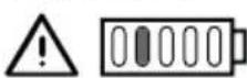 | Battery detection/communication error | Switch off the machine and repeat the starting procedure |
| Check the correct mounting/installation of the batteries in their respective slots. | ||
| If the problem persists, contact a Service Centre. | ||
15. The icon in fig. 7.E remains ON and battery LEDs2, 3, 4 and 5 flash. | Parallel module electronics error. Switch off the machine and repeat the starting procedure |
| If the problem persists, contact a Service Centre. | |
| 16. The battery LEDs in fig. 7.F turn ON and OFF in sequence, from left to right, and vice versa. | Communication error between on-board electronic modules. |
17. The icon in fig. 7.E remains ON and battery LEDs 3 and 4 flash. | Incorrect battery configuration installed. |
NOTE
For any further problems not listed in the table, immediately contact an Authorized Assistance Centre.
16. ATTACHMENTS
16.1 "MULCHING" KIT
Finely chops the grass cuttings and deposits them on the lawn (fig. 36 A).
16.2 BATTERY CHARGER (FAST CHARGE)
This battery charger helps reduce battery recharging time. The list of type-approved battery chargers for this machine can be found in the “Technical Data” table.
This keeps the battery in good working order when the machine is in storage, guaranteeing an optimum level of charge and longer battery life (fig. 36.B).
16.3 REAR DISCHARGE GUARD KIT
Can be used in place of the grass catcher when mown grass is not collected (Fig. 36.C).
ÍNDICE
natural_image
Simple diagram of a vehicle with four wheels and a downward arrow, no text or symbols present.natural_image
Simple line drawing of a vehicle with four wheels and a downward arrow (no text or symbols)| Estado de carga (SOC) | Encendido led |
| SOC > 80% | |
| 60% ≤ SOC < 80% | 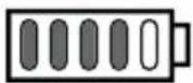 |
| 40% ≤ SOC < 60% | 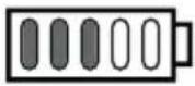 |
| 20% ≤ SOC < 40% | 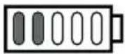 |
| 10% ≤ SOC < 20% |  |

AVISO
16.1 KIT PARA "MULCHING"
1.1 KUIDAS JUHENDIT LUGEDA
2. MASINA ÜLDISED OHUTUSHOIATUSED
2.1 ÜLDISED OHUTUSHOIATUSED
HOIATUS
| Laadimisolek (SOC) Led SEES | |
| SOC > 80% | |
| 60% ≤ SOC < 80% | |
| 40% ≤ SOC < 60% | |
| 20% ≤ SOC < 40% | 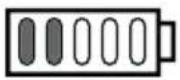 |
| 10% ≤ SOC < 20% | 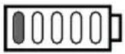 |

MÄRKUS
b. Irrotetun akun lataus
Akun lataaminen:
11. MANUTENTION ET TRANSPORT
16.1 KIT DE MULCHING
- UPORABA STROJA....15
7.1 Pripremne radnje.... 15
7.2 Sigurnosne kontrole.... 16
7.3 Uporaba na terenima s nagibom ..... 17
7.4 Pokretanje 17
7.5 Rad....18
7.6 Zaustavljanje 19
7.7 Nakon korištenja.... 19
- REDOVNO ODRŽAVANJE....19
Ikona "Ready" (Spreman)
Ikona sl. 7.K se pali kad je stroj upaljen i spreman za uporabu.

Ikona "Bluetooth"
Gumb "CRUISE CONTROL"
Pritiskom gumba sl. 7.G uključuje se/isključuje funkcija "CRUISE CONTROL".
Ikona "Ready" (Spreman)
Ikona sl. 7.K se pali kad je stroj upaljen i spreman za uporabu.

Ikona "Bluetooth"
7.3 UPORABA NA TERENIMA S NAGIBOM
Poštujte ograničenja koja se navode u tablici "Tehnički podaci" i na sl. 12, bez obzira na smjer kretanja.
Imajte na umu da ne postoji "sigurna" padina. Kretanje po terenima s nagibom zahtijeva posebnu pozornost. Kako biste izbjegli prevrtanja ili gubitak kontrole nad strojem:
b. Punjenje baterije izvan stroja
Za punjenje baterije:
- Otvorite vratašca (sl. 20.A) sjedišta baterija;
- Pritisnite gumb za deblokiranje koji se nalazi na bateriji (sl. 32.A) i izvadite bateriju (sl. 32.B);
- Stavite bateriju (sl. 33.A) u njezino sjedište na punjaču baterija (sl. 33.B);
- Spojite punjač baterija (sl. 33.B) na električnu utičnicu čiji napon odgovara onome navedenom na označnoj pločici;
- Potpuno je napunite pridržavajući se uputa iz priručnika za punjač baterija.
- Po dovršenom punjenju izvadite bateriju (sl. 34.A) iz njezinog sjedišta na punjaču baterija (sl. 34.B).
- Iskopčajte punjač baterija (sl. 34.B) iz električne mreže.
- Ponovno stavite bateriju (sl. 35.A) u njezino sjedište na stroju i zatvorite vratašca sjedišta baterija.
Baterije se mogu puniti neodređeno vrijeme.
| Stanje napunjenosti (SOC) | Paljenje LED svjetala |
| SOC > 80% | |
| 60% ≤ SOC < 80% | |
| 40% ≤ SOC < 60% |  |
| 20% ≤ SOC < 40% | 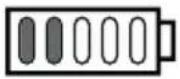 |
| 10% ≤ SOC < 20% |  |

OBAVIJEST
natural_image
Simple line drawing of a vehicle with four wheels and a downward arrow (no text or symbols)natural_image
Simple line drawing of a vehicle with four wheels and a downward arrow (no text or symbols)- PLĀNOTĀ TEHNISKĀ APKOPE......19
8. PLĀNOTĀ TEHNISKĀ APKOPE
8.1 VISPĀRĒJA INFORMĀCIJA

BRIESMAS
9.4 LED SPULDŽU MAINA
2. ALGEMENE VEILIGHEIDSWAARSCHUWINGEN
2.1 ALGEMENE VEILIGHEIDSWAARSCHUWINGEN
WAARSCHUWING
3.5 BESCHERMING VAN DE OMGEVING
6.7 AKOESTISCH SIGNAALAPPARAAT
| Status lading (SOC) Verlichting led | |
| SOC > 80% | |
| 60% ≤ SOC < 80% | |
| 40% ≤ SOC < 60% | 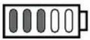 |
| 20% ≤ SOC < 40% | 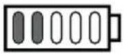 |
| 10% ≤ SOC < 20% | 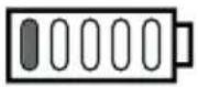 |
KENNISGEVING
- BLI KJENT MED MASKINEN 7
- ORDINÆRT VEDLIKEHOLD....19
- EKSTRAORDINÄERT VEDLIKEHOLD.....23
VEDLIKEHOLD, LAGRING
4. BLI KJENT MED MASKINEN
4.1 BESKRIVELSE AV MASKINEN OG BEREGNET BRUK
Denne maskinen er en traktorklipper.
6.3 SPAK FOR INNKOBLING / UTKOBLING AV TRANSMISJONEN
6.8.1 Knappanel (type "I") fig. 7
Startknapp for maskin
Knapp for klipping i revers
Knapp for klipping i revers
7.1 INNLEDENDE OPPGAVER
8. ORDINÆRT VEDLIKEHOLD
8.1 GENERELT
FARE
| Ladestatus (SOC) Tenning av LED-lys | |
| SOC > 80% |  |
| 60% ≤ SOC < 80% |  |
| 40% ≤ SOC < 60% |  |
| 20% ≤ SOC < 40% |  |
| 10% ≤ SOC < 20% |  |

MELDING
RYZYKO WYWRÓCENIA MASZYNY
| Estado de carga (SOC) | Acendimento do LED |
| SOC > 80% | 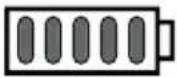 |
| 60% ≤ SOC < 80% |  |
| 40% ≤ SOC < 60% | 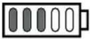 |
| 20% ≤ SOC < 40% |  |
| 10% ≤ SOC < 20% |  |

AVISO
16.1 KIT PARA "MULCHING"
| Starea de încărcare (SOC) | Illuminarea cu LED |
| SOC > 80% | 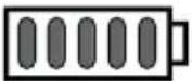 |
| 60% ≤ SOC < 80% |  |
| 40% ≤ SOC < 60% |  |
| 20% ≤ SOC < 40% |  |
| 10% ≤ SOC < 20% |  |
AVERTISMENT
16.1 KIT PENTRU MULCI
3.5 OCHRANA ŽIVOTNÉHO PROSTREDIA
7.5 PRACOVNÁ ČINNOST
7.5.1 Jazda a presuny
Počas presunu:
- UPORABA STROJA....15
7.1 Začetna opravila.... 15
7.2 Varnostni pregledi....16
7.3 Uporaba na nagnjenih terenih ..... 17
7.4 Zagon....17
7.5 Delo....18
7.6 Zaustavitev....19
7.7 Po uporabi 19
- REDNO VZDRŽEVANJE 20
b. Polnjenje baterije zunaj stroja Polnjenje baterije:
b. Napunjenost eksternih baterija
Da biste napunili bateriju:
- Otvorite vratanca (slika 20.A) ležišta za baterije;
- Pritisnite taster za deblokadu koji se nalazi na bateriji (slika 32.A) i izvadite bateriju (slika 32.B);
- Stavite bateriju (slika 33.A) u ležište na punjaču baterije (slika 33.B);
- Uključite punjač baterije (slika 33.B) u utičnicu sa naponom koji odgovara podacima navedenim na nalepnici;
- Napunite bateriju do kraja, prema uputstvima iz priručnika za punjač baterija.
- Kada se punjenje završi, izvadite bateriju (slika 34.A) iz ležišta punjača baterija (slika 34.B).
- Isključite punjač baterija (slika 34.B) iz utičnice napajanja.
- Ponovo postavite bateriju (slika 35.A) u ležište na mašini i zatvorite vratanca ležišta za baterije.
| Stanje punjenja (SOC) | Uključuje se LED |
| SOC > 80% | |
| 60% ≤ SOC < 80% | |
| 40% ≤ SOC < 60% | |
| 20% ≤ SOC < 40% | |
| 10% ≤ SOC < 20% | |

OBAVEŠTENJE
INNEHÅLLSFÖRTECKNING
- ALLMÄN INFORMATION...... 2
- ALLMÄNNA SÄKERHETSFÖRESKRIFTER 2
- SÄKERHETSFÖRESKRIFTER FÖR ÄKGRÄSKLIPPAREN 5
WARNING FÖR KROSSNING
6.3 SPAK FÖR ATT KOPPLA IN/UR KRAFTÖVERFÖRINGEN
b. Batteriladdning ej ombord
| Laddningsstatus (SOC) | Led ljus |
| SOC > 80% | 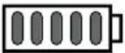 |
| 60% ≤ SOC < 80% |  |
| 40% ≤ SOC < 60% | 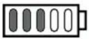 |
| 20% ≤ SOC < 40% | 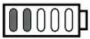 |
| 10% ≤ SOC < 20% | 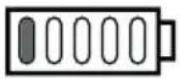 |

OBS
UK DECLARATION OF CONFORMITY
(Supply of Machinery (Safety) Regulations 2008, S.I. 2008 No. 1597, Annex II, part A)
- The company: ST. S.p.A. – Via del Lavoro, 6 – 31033 Castelfranco Veneto (TV) – Italy
- Hereby declares under its own responsibility that the machine:
Ride-on lawnmower with seated operator (grass cutting)
a) Homologation type: R 72 Li 48 V1 - R 72 Li 48 V2
c) Serial number: 22A••RON000001 ÷ 99L••RON999999
d) Engine: battery-operated
- Conforms to UK Regulations:
• S.I. 2008/1597 - Supply of Machinery (Safety) Regulations 2008
• S.I. 2001/1701 - Schedule 9 - Noise Emission in the Environment by Equipment for use Outdoors Regulations 2001
e) Notified body: N. 0197 – TÜV Rheinland LGA Products GmbH
Tillystrasse 2, 90431 Nürnberg – Germany
• S.I. 2016/1091 - Electromagnetic Compatibility Regulations 2016
• S.I. 2012/3032 - The Restriction of the Use of Certain Hazardous Substances in Electrical and Electronic Equipment Regulations 2012
• S.I. 2017/1206 - Radio Equipment Regulations 2017
- Reference to harmonised standards:
EN 62841-1:2015 + AC:2015
EN ISO 5395-1:2013 + A1:2018
EN ISO 5395-3:2013 + A1:2017 + A2:2018
EN 62368-1:2014 + A1:2017
EN 55014-1:2021
EN 55014-2:2021
EN 63000:2018
EN 300328 V2.2.2
EN 301489-1 V2.2.3
EN 301489-17 V3.2.4
EN 62479:2010
g) Measured sound power level:
h) Guaranteed sound power level:
i) Cutting width:
n) Person authorised to compile the technical file:
96,8 dB(A)
98 dB(A)
72 cm
ST. S.p.A.
Via del Lavoro, 6
31033 Castelfranco Veneto (TV) - Italia
o) Castelfranco Veneto, 01/10/2022 CEO Stiga Group
Sean Robinson

UK Importer: STIGA LTD
Unit 8, Bluewater Estate Plympton,
Devon, PL7 4JH, England

| FR (Traduction de la notice originale)Déclaration CE de Conformité(Directive Machines 2006/42/CE, Annexe II, partie A)1. La Société2. Déclare sous sa propre responsabilité que la machine : Tondeuse à gazon à conducteur assis/ coupe du gazona) Type / Modèle de Basec) S éried) Moteur: batterie3. Est conforme aux prescriptions des directives :e) Organisme de certification4. Renvoi aux Normes harmoniséesg) Niveau de puissance sonore mesuréh) Niveau de puissance sonore garanti) Largeur de coupen) Personne habilitée à établir le Dossier Technique :o) Lieu et Date | EN (Translation of the original instruction)EC Declaration of Conformity(Machine Directive 2006/42/EC, Annex II, part A)1. The Company2. Herby declares under its own responsibility that the machine: ride-on lawnmower with seated operator/ Grass cuttinga) Type / Base Modelc) Serial numberd) Motor: battery-operated3. Conforms to directive specifications:e) Certifying body4. Reference to harmonised Standardsg) Sound power level measuredh) Sound power level guaranteedi) Cutting widthn) Person authorised to create the Technical Folder:o) Place and Date | DE (Übersetzung der Originalbetriebsanleitung)EG-Konformitätserklärung(Maschinenrichtlinie 2006/42/EG, Anhang II, Teil A)1. Die Gesellschaft2. Erklärt auf eigene Verantwortung, dass die Maschine: Aufsitzmäher / Rasenschnitta) Typ / Basismodellc) Seriennummerd) Motor: Batterle3. Den Anforderungen der folgenden Richtlinien entspricht:e) Zertifizierungsstelle4. Bezugnahme auf die harmonisierten Normeng) Gemessener Schalleistungspegelh) Garantierter Schalleistungspegeli) Schnittbreiten) Zur Verfassung der technischen Unterlagen befugte Person:o) Ort und Datum |
| NL (Vertaling van de oorspronkelijke gebruiksaanwijzing)EG-verklaring van overeenstemming(Richtlijn Machines 2006/42/CE, Bijlage II, deel A)1. Het bedrijf2. Verklaart onder zijn eigen verantwoordelijkheld dat de machine: Grasmaalier met zittende bediener / grasmaalera) Type / Basismodelc) Serienummerd) Motor: accu3. Voldoet aan de specificaties van de richtlijnen:e) Certificatie-instituut4. Verwijzing naar de Geharmoniseerde normeng) Gemeten niveau van geluidsvermogenh) Gegarandeerd niveau van geluidsvermogeni) Snijbreedten) Bevoegd persoon voor het opstellen van het Technisch Dossiero) Plaats en Datum | ES (Traducción del Manual Original)Declaración de Conformidad CE(Directiva Máquinas 2006/42/CE, Anexo II, parte A)1. La Empresa2. Declara bajo su propia responsabilidad que la máquina: Cortadora de pasto con conductor sentado/ Corte hierbaa) Tipo / Modelo Basec) M atriculad) Motor: bateria3. Cumple con las especificaciones de las directivas:e) Ente certificador4. Referencia a las Normas armonizadasg) Nivel de potencia sonora medidoh) Nivel de potencia sonora garantizadoi) Amplitud de corten) Persona autorizada a realizar el Manual Técnico:o) Lugar y Fecha | PT (Tradução do manual original)Declaração CE de Conformidade(Diretiva de Máquinas 2006/42/CE, Anexo II, parte A)1. A Empresa2. Declara sob a própria responsabilidade que a máquina: Corta-relvas para operador sentado/ corte da relvaa) Tipo / Modelo Basec) M atriculad) Motor: Bateria3. É conforme às especificações das diretivas:e) Órgão certificador4. Referência às Normas harmonizadasg) Nível medido de potência sonorah) Nível garantido de potência sonorai) Amplitude de corten) Pessoa autorizada a elaborar o Caderno Técnicoo) Local e Data |
| EL (Μετάφραση του πρωτοτύπου των οδηγιών χρήσης)ΕΚ-Δήλωση συμμόρφωσης(Οδηγία Μηχανών 2006/42/CE, Παράρτημα II, μέρος A)1. Η Εταιρία2. Δ ηλώνει υπεύθυνα ότι η μηχανή:Χλοοκοπτικό τρακτέρ με εποχούμενο χειριστή/ κοπή της χλόηςa) Τύπος / Βασικό Μοντέλος) Αριθμός μητρώου d) Κινητήρας: μπαταρία3. Σ υμμορφώνεται με τις προδιαγραφές της οδηγίας:e) Οργανισμός πιστοποίησης4. Αναφορά στους Κανονισμούς εναρμόνισηςg) Στάθμη μέτρησης ακουστικής ισχύοςh) Στάθμη εγγυημένης ακουστικής ισχύοςi) Έύρος κοπήςn) Εξουσιοδοτημένο άτομο για την κατάρτιση του Τεχνικού Φυλλαδίου:o) Τόπος και Χρόνος | TR (Orijinal Talimatların Tercümesi)AT Uygunluk Beyani(2006/42/CE Makine Direktifi, Ek II, bölüm A)1. Şirket2. § ahsi sorumluluğu altında aşağıdaki makinenin: Oturan sürücülü çim biçme makinesi / çim kesimia) Tip / Standart modelc) Sicil numarasid) Motor: batarya3. Aşağıdaki direktiflerin özelliklerlne uygun olduğunu beyan etmektedir:e) Sertifikalandiran kurum4. Ḍharonize standartlara atıfg) Ölçülen ses güc seviyesih) Garanti edilen ses güc seviyesiI) Kesim genişliğin) Teknik Dosyayı oluşturmaya yetkili kişi:o) Yer ve Tarih | MK (Превод на оригиналните упатства)Декларација за усогласеност со ЕУ (Директива за машини 2006/42/CE, Анекс II, дел A)1. Компанијата2. изјавува со целосна лична одговорност дека следната машина: Тревокосачка со седнат управувач / косење треваa) Tip / основен моделв) етикетаг) мотор: акумулатор3. Усогласено со спецификациите според директивите:д) тело за сертификација4. Референци за усогласени нормативие) Акустички притисокж) измерено ниво на звучна мокност з) Ниво на гарантирана звучна мокност н) овластено лице за составување на Техничката брошурао) место и датум |
| NO (Oversettelse av original bruksanvisning)EF- Samsvarserklæring(Maskindirektiv 2006/42/EF, Vedlegg II, del A)1. Firmaet2. Erklærer på eget ansvar at maskinen: Sittegressklipper / gressklippinga) Type / Modellc) Serienummerd) Motor: batteri3. Oppfyller kravene i direktivene:e) Sertifiseringsorgan4. Henvisning til harmoniserte standarderg) Målt lydeffektnivåh) Garantert lydeffektnivåi) Klippebredden) Person som har fullmakt til å utferdigeteknisk dokumentasjon:o) Sted og dato | SV Översättning av bruksanvisning i original)EG-försäkran om överensstämmelse (Maskindirektiv 2006/42//EG, bilaga II, dela)1. Företaget2. Försäkrar på eget ansvar att maskinen Åkgräsklippare / gräsklippinga) Typ / Basmodellc) S erienummerd) Motor: batteri3. Överensstämmer med föreskrifterna i direktivete) Intygsorgan _ Anmält organ4. Referens till harmoniserade standarderg) Uppmätt ljudeffektnivåh) Garanterad ljudeffektnivåi) Skärbreddn) Auktoriserad person för upprättandet av den tekniska dokumentationen:o) Ort och datum | DA (Oversættelse af den originale brugsanvisning)EF-overensstemmelseserklæring (Maskindirektiv 2006/42/EF, bilag II, del A)1. Firmaet2. Erklærer på eget ansvar, at maskinen: Havetraktor/ klipning af græseta) Type / Modelc) Serienummerd) Motor: batteri3. Er i overensstemmelse med specifikationerne ifølge direktiverne:e) Certificeringsorgan4. Henvisning til harmoniserede standarderg) Målt lydeffektniveauh) Garanteret lydeffektniveaui) Klippebredden) Person, der har bemyndigelse til at udarbejde det tekniske dossier:o) Sted og dato |
| FI (Alkuperäisten ohjeiden käännös)EY-VAATIMUSTENMUKAISUUSVAKUUTUS (Konedirektliví 2006/42/EY, Llite II, osa A)1. Yritys2. Vakuuttaa omalla vastuillaan, että kone: Päältäjettava ruohonleikkuri / ruohonleikkuaa) Tyyppl / Perusmallic) S arjanumerod) Moottori : akku3. On yhdenmukalnen seuraavlen direktiivien asettamien vaatimustenkanssa:e) Sertifointiyritys4. Viltaus harmonisoituihin standardeihing) Mitattu äänitehotasoh) Taattu äänitehotasoi) Leikkuuleveysn) Teknisten aslakirjojen laatimiseenvaltuutettu henkilö:o) Paikka ja pälvämäärä | CS Překlad původního návodu k používání)ES – Prohlášení o shodě (Směrnice o Strojních zařízeních 2006/42/ES, Přiloha II, část A)1. Společnost2. Prohlašuje na vlastní odpovědnost, že stroj: Sekačka se sedící obsluhou/sekačka na trávua) Typ / Základní modelc) Výrobní číslod) Motor: akumulátor3. Je ve shodě s nařízeníml směrnic:e) Certifikační orgán4. Odkazy na Harmonizované normyg) Naměřená úroveň akustického výkonuh) Zaručená úroveň akustického výkonui) Šířka režánín) Osoba autorizovaná pro vytvoření Technického spisu:o) Místo a Datum | PL (Tłumaczenie instrukcji oryginalnej)Deklaracja zgodności WE (Dyrektywa maszynowa 2006/42/WE, Załącznik II, część A)1. Spółka2. Oświadcza na własną odpowiedzialność, że maszyna: Kosiarka z operatorem jadącym, w pozycjisiedzącej na maszynie/ cięcie trawya) Typ / Model podstawowyc) Numer seryjnyd) Silnik: akumulator3. Spelnia podstawowe wymoginastępujących Dyrektyw:e) Jednostka certyfikująca4. Odnleslenie do Normzharmonizowanychg) Zmlerzony poziom mocy akustycznejh) Gwarantowany poziom mocyakustyczneji) Szerokość cięcian) Osoba upoważniona do zredagowania Dokumentacji technicznej:o) Mlejscowość i data |
| HU (Eredeti használati utasítás fordítása)EK-megfelelőségi nyilatkozata (2006/42/EK géplírányelv, II. melléklet "A" rész)1. Alulírott Vállalat2. Felelősségének teljes tudatábankljelentí, hogy az alábbi gép: Vezetőüléses fünyírógép/fünyírásaa) Típus / Alaptípusc) G yártási számd) Motor: akkumulátor3. Megfelel az alábbi irányelvekelőírásalnak:e) Tanúsító szerv4. Hivatkozás a harmonizált szabványokrag) Mért zajteljesítmény szinth) Garantált zajteljesítmény szinti) Vágási szélességn) Műszaki Dosszié szerkesztésérefelhatalmazott személy:o) Helye és ideje | RU (Перевод оригинальных инструкций)Декларация соответствия нормам EC (Директива о машинном оборудовании 2006/42/EC, Приложение II, часть A)1. Предприятие2. Заявляет под собственнуюответственность, что машина: Ездовая косилка с водителем / стрижка газона) Тип / Базовая модельс) Паспортd) Двигатель: : батарея3. Соответствует требованиям следующих директив:e) Сертифицирующий орган4. Ссылки на гармонизированныенормыg) Измеренный уровень звуковой мощностиh) Гарантируемый уровень звуковой мощностиi) Амплитуда кошенияn) Лицо, уполномоченное на подготовку технической документации:o) Место и дата | HR (Prijevod originalnih uputa)EK Izjava o sukladnosti (Direktiva 2006/42/EZ o strojevima, dodatak II, dio A)1. Tvrtka:2. pod vlastitom odgovornošću izjavljujeda je stroj: Sjedeća kosillca trave s operaterom/ košenje travea) Vrsta / Osnovni modelc) Matični brojd) Motor: baterija3. sukladan s temeljnim zahtjevimadirektiva:e) Certifikacijsko tijelo4. Primijenjene su slijedeće harmonizirane norme:g) Izmjerena razina zvučne snageh) Zajamčena razina zvučne snagei) Širina rezanjan) Osoba ovlaštena za pravljenje Tehničke datoteke:o) Mjesto i datum |
| SL (Prevod izvirnih navodil)ES izjava o skladnosti(Direktiva 2006/42/ES) , priloga II, del A)1. Družba2. pod lastno odgovornostjo izjavlja, da je stroj: Traktorska kosilnica/ košnja travea) Tip / osnovni modelc) Serijska številkad) Motor: baterija3. Skladen je z določili direktiv :e) Ustanova, ki izda potrdilo4. Sklicevanje na usklajene predpiseg) Izmerjen nivo zvočne močih) Zagotovljen nivo zvočne moči) Obseg košnjen) Oseba, pooblaščena za sestavotehnične knjižice:o) Kraj in datum | BS (Prijevod originalnih uputa)EZ izjava o sukladnosti(Direktiva o mašlnama 2006/42/EZ, PrilogII, deo A)1. F Irma2. Daje izjavu pod vlastitomodgovornošću da je mašina: Traktorskakosilica (traktorčić) / Košenje travea) Tip / Osnovni modelc) Serijski brojd) Motor: akumulator3. sukladna s osnovnim zahtjevimadirektive:e) Certifikaciono tijelo4. Pozlivanje na uskladene normeg) Izmjereni nivo zvučne snageh) Garantovani nivo zvučne snagei) Širina košenjan) Osoba ovlaštena za izradu tehničkebrošure:o) Mjesto i datum | SK (Preklad pôvodného návodu na použitie)ES vyhlásenie o zhode(Smernlica o Strojných zarladenlach2006/42/ES, Príloha II, čast' A)1. Spoločnosť2. Vyhlasuje na vlastnú zodpovednosť, žestroj: Kosačka so sedlacou obsluhou/kosačka na trávua) Typ / Základný modelc) Výrobné čislod) Motor: akumulátor3. Je v zhode s nariadeniami smerníc:e) Certifikačný orgán4. Odkaz na Harmonizované normyg) Nameraná úroveň akustického výkonuh) Zaručená úroveň akustického výkonui) Širka koseniaj) Čistý Inštalovaný výkonn) Osoba autorizovaná na vytvorenieTechnického spisu:o) Miesto a Dátum |
| RO (Traducerea manualului fabricantului)CE -Declaratie de Conformitate(Directiva Maşini 2006/42/CE, Anexa II,partea A)1. Societatea2. Declară pe propria răspundere cămașina: Mașină de tuns iarba cu șofer lavolan/ tăiat iarbaa) Tip / Model de bazăc) Număr de seried) Motor: baterie3. E ste în conformitate cu specificațiiledirectivelor:e) Organism de certificare4. Referință la Standardele armonizateg) Nivel de putere sonoră măsurath) Nivel de putere sonoră garantati) Lățimea de tăieren) Persoană autorizată să întocmeascăDosarul Tehnico) Locul și Data | LT (Originalių instrukcijų vertimas)EB atitikties deklaracija(Mašinų direktyva 2006/42/CE, Priedas II,dalis A)1. Bendrovė2. Prisiima atsakomybę, kad jrenginys:Balninė vejapjovė su sédinčiuoperatoriumi / žolės pjovimasa) Tipas / Bazinis Modelisc) Serijos numerisd) Variklis: baterija3. Atitinka direktyvose pateiktasspecifikacijas:e) Sertifikavimo įstaiga4. Nuoroda j suderintas Normasg) Išmatuotas garso galios lygish) Užtikrinamas garso galios lygisi) Pjovimo plotisn) Autorizuotas asmuo sudaryti TechninęDokumentacija:o) Vieta ir Data | LV (Instrukciju tulkojums no originálvalodas)EK atbilstības deklarācija(Direktīva 2006/42/EK par mašinām,pielikums II, dala A)1. U zpēmums2. Uznemoties par to pilnu atbildību,paziņo, ka mašina: Sêžot vadāma zālienuplaujmašina/ zāles plaušanaa) Tips / Băzes modelisc) Sērijas numursd) Motors: akumulators3. Atbilst šādu direktīvu prasībām:e) Sertifikācijas iestäde4. Atsauce uz harmonizētiem standartiemg) Izměrītais skaņas intensitātes līmenish) Garantētais skaņas intensitātes līmenisi) Plaušanas platumsn) Pilnvarotais darbinieks, kas sagatavojatehnisko dokumentāciju:o) Vieta un datums |
| SR (Prevod originalnih uputstval)EC deklaraclja o usaglašenostl(Direktiva o mašinama 2006/42/EC, PrilogII, deo A)1. Preduzeće2. Daje izjavu pod vlastitomodgovornošću da je mašina: Traktorskakosačica (traktorčić)/ košenje travea) Tip / Osnovni modelc) Serijski brojd) Motor: akumulator3. u skladu s osnovním zahtevlimadirektiva:e) Sertifikaciono telo4. Pozivanje na uskladene normeg) Izmereni nivo zvučne snageh) Garantovani nivo zvučne snagei) Širina košenja......n) Osoba ovlašćena za sastavljanjetehničke brošureo) Mesto i datum | BG ( Превод на оригиналните инструкции)EO декларация за съответствие(Директива Машини 2006/42/EO,Приложение II, част A)1. Дружеството2. На собствена отговорност декларира,че машината: Косачка със седнал водач/рязане на треваa) Вид / Базисен моделв) Сериен номерг) Мотор: акумулатор3. Е в съответствие със спецификата надирективите:д) Сертифициращ орган4. Базирano на хармонизираните нормиж) Ниво на измерена акустична мощности) Гарантирано ниво на акустична мощностй) Широчина на косенер) Лище, упълномощено да съставиТехническата Документация:o) Място и дата | ET (Algupārase kasutusjuhendi tõlge)EÜ vastavusdeklaratsloon(Masinadirektiiv 2006/42/EÜ, Lisa II, osa A)1. Firma2. Kinnitab omal vastutusel, et masin:Istuva juhiga murunlitja / murunlitjaa) Tüüp / Põhimudelc) Matrikkeld) Mootor: aku3. Vastab direktlivide nõuetele:e) Kinnitav asutus4. Vilde ühlustatud standarditeleg) Möõdetud helivõimsuse taseh) Garanteeritud helivõimsuse tasei) Löikelaiusn) Tehnllse Lehe autoriseeritud koostaja:o) Koht ja Kuupäev |
EN • The content and images in this User Manual were produced expressly for ST. S.p.A. and are protected by copyright – any unauthorised reproduction or modification to the document, either partially or in full, is prohibited.
Type: