USER MANUAL Tornado 398e STIGA
MPST 84 Li 48 V1 / V2
MPS 84 Li 48 V1 / V2
MPNS 84 Li 48 V1 / V2
MP 84 Li 48 V1 / V2
MPX 84 Li 48 V1
SDST 98 Li 48 V1 / V2
SDS 98 Li 48 V1 / V2
SDNS 98 Li 48 V1 / V2
SD 98 Li 48 V1 / V2
SDX 98 Li 48 V1
MPST 98 Li 48 V3
MPS 98 Li 48 V3
MPNS 98 Li 48 V3
MP 98 Li 48 V3
MPX 98 Li 48 V3
SDST 108 Li 48 V3
SDS 108 Li 48 V3
SDNS 108 Li 48 V3
SD 108 Li 48 V3
SDX 108 Li 48 V3


natural_image
Icon of a person reading a book inside a circle (no text or symbols)

natural_image
Abstract line drawing of a stylized animal or creature (no text or symbols)
EN Ride-on lawnmower with seated operator, battery-operated OPERATOR'S MANUAL
WARNING: read thoroughly the instruction booklet before using the machine.
ENGLISH - Translation of the original instruction ...... EN
2
4

12
13
1
||
natural_image
Illustration of a hand holding a gauge tool next to a car tire, no text or symbols present
natural_image
Diagram of a vehicle's front wheel and blade assembly with motion lines, no text or symbols present
natural_image
Diagram of a coiled tube or coil structure with directional arrows, no text or symbols present


natural_image
Line drawing of a cable inserted into an electrical socket (no text or symbols)
natural_image
Diagram of a car's engine component being adjusted with a fuel nozzle, showing internal structure and wiring (no text or symbols)
31
natural_image
Technical line drawing of a mechanical assembly with three circular components and connecting rods (no text or symbols)
32

44
natural_image
Mechanical assembly diagram showing a lever mechanism with labeled component A1 (no text or symbols beyond label)
natural_image
Technical diagram of a vehicle's intake manifold with labeled component A2 (no text or symbols beyond label)
natural_image
Illustration of a portable electronic device with coiled cables and connectors (no text or symbols)
natural_image
Technical line drawing of a vehicle's front suspension system with labeled component (no text or symbols)
natural_image
Technical line drawing of a mechanical assembly with labeled component 'C' (no text or symbols beyond label)
natural_image
Illustration of a covered outdoor vehicle with a large dome and wheels, labeled 'D' (no text or symbols on the vehicle itself)
natural_image
Technical line drawing of a mechanical component with no visible text or symbols
natural_image
Technical line drawing of a manual pushrower with wheels and handle (no text or symbols)
natural_image
Technical line drawing of a tire with labeled component G (no text or symbols beyond label)
natural_image
Line drawing of a two-wheeled push truck with a handle and wheels, labeled 'H' (no text or symbols on the diagram itself)
natural_image
Technical line drawing of a mechanical tool or bracket with a curved handle and base, labeled 'K' (no text or symbols beyond the label)
natural_image
Technical line drawing of a manual pushrower with labeled component 'J' (no text or symbols beyond label)
[16] Pumpetryk for bagdæk
[17]Vægt(*)
[43] USB-ZUBEHÖRSTECKDOSE
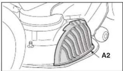
[44.A1, 42.A2] Σετ "mulching"
[2] Power supply voltage MAX
[3] Power supply voltage NOMINAL
[4] Max. motor operating speed
[5] Battery
[5a] With Lithium ions (Li-on)
[6] Battery capacity
[7] Battery charger
[8] Maximum charge duration
[9] Traction motor power
[10] Blade motor power
[11] Frequency band(s) in which the radio equipment operates
[12] Maximum radio-frequency power transmitted in the frequency band(s) in which the radio equipment operates
[13] Front tyres
[14] Rear tyres
[15] Front tyre pressure
[16] Rear tyre pressure
[17]Mass(*)
[18] Minimum radius of uncut grass
[19]Cuttingheight
[20] Cutting width
[21] Forward travel speed (indicative)
[22] Reverse travel speed (indicative)
[23] Maximum admissible tilt
[24] Dimensions
[25]Length
[26] Length with grass catcher (length without grass catcher)
[27]Width
[28] Width with side discharge chute (Width without side discharge chute)
[29]Height
[30] Cutting means code
[31]Soundpressurelevel
[32] Measurement uncertainty
[33] Measured sound power level
[34] Guaranteed sound power level
[35] Operator position vibration level
[36] Steering wheel vibration level
[44] Accessories available on request
[44.A1, 42.A2] "Mulching" kit
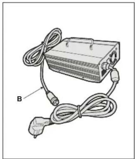
[44.B] Battery charger
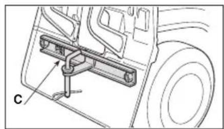
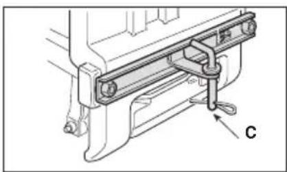
[44.C] Towing kit
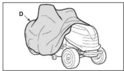
[44.D] Cloth cover
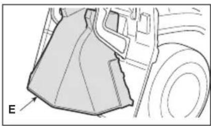
[44.E] Rear discharge guard kit (only for MP series)
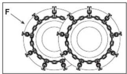
[44.F] Snow chains
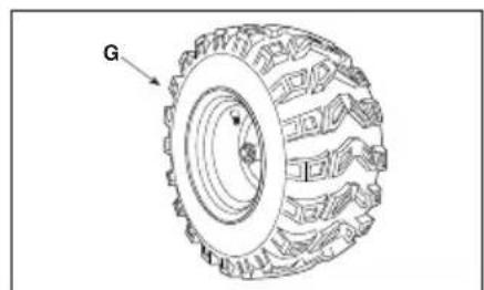
[44.G] Mud / Snow wheels
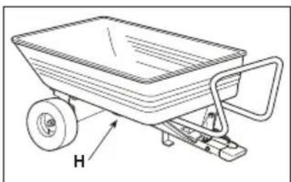
[44.H]Trailer
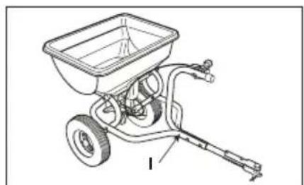
[44.1] Sprinkler
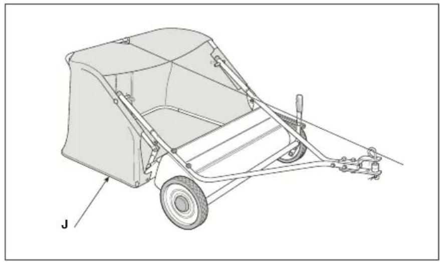
[44.J] Leaf and grass catcher
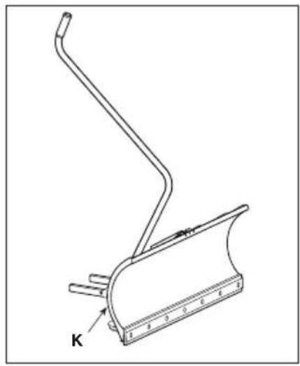
[44.K] Snow shovel
[43] AUXILIARY PORT FOR USB ACCESSORIES
[43.A] Charging voltage and current (Output USB)
[43.B] Type
[43.C] Name and address of Manufacturer
* Please refer to the data indicated on the machine's identification plate for the exact figure.
[1] ES - DATOS TÉCNICOS
[3] Toite pinge NOMINAL
[14] Tagumised rehvid
[1] FI-TEKNISET TIEDOT
[5a] Lithium-ions (Li-on)
[1] LT - TECHNINIAI DUOMENYS
[2] Maitinimo jtampa MAX
[3] Maitinimo jtampa NOMINAL
[4] Maksimalus variklio veikimo greitis
[5] Akumuliatorius
[2] Spanning voeding MAX
[3] Spanning voeding NOMINAL
[43] AUX-AANSLUITING VOOR USB-ACCESSOIRES
[43.A] Laadspanning en -stroom (Uitgang USB)
[43.B] type
[43.C] Naam en adres van de fabrikant
[44.A1, 42.A2] Mulching-sett
[44.B]Batterilader
[3] Spänning NOMINAL
[4] Motorns maximala funktionshastighet
[5] Batteri
[5a] Litiumjon (Li-on)
[6] Batteriets kapacitet
[7]Batteriladdare
[8] Laddningens maximala varaktighet
[9] Drivmotorns effekt
[10] Bladmotorns effekt
- USO DELLA MACCHINA 20
3.4 MANUTENZIONE, RIMESSAGGIO
7. USO DELLA MACCHINA
AVVERTIMENTO
| Stato carica (SOC) | Accensione led (tipo “I” e “II”) | Accensione led (tipo “III”) |
| 60% ≤ SOC < 80% |  | |
| 40% ≤ SOC < 60% |  | |
| 20% ≤ SOC < 40% |  | |
| 10% ≤ SOC < 20% |  | |

ATTENZIONE
16.1 KIT PER MULCHING
7.5 PRACOVNÍ ČINNOST
Ikon for opsamlingspose
For at skifte position:
For at skifte position:
16.1 KIT TIL "MULTICLIP"
16.3 KIT TIL TRÆKNING
16.5 KIT HINTERER AUSWURFSCHUTZ
- XEIPISTHPIA EΛΕΓΧΟΥ .....12
- GENERAL INFORMATION......2
- GENERAL MACHINE SAFETY
WARNINGS....2
- SAFETY WARNINGS FOR RIDE-ON
LAWN MOWER WITH SEATED
OPERATOR....5
3.1 Training....5
3.2 Preliminary operations.... 5
3.3 During operation....5
3.4 Maintenance, storage....6
3.5 Environmental protection....7
- ABOUT THE MACHINE....7
4.1 Machine description and intended use....7
4.2 Safety signs....8
4.3 Identification label 9
4.4 Main components....9
- ASSEMBLY 9
5.1 Assembly components.... 10
5.2 Steering wheel assembly.... 10
5.3 Seat assembly.... 10
5.4 Mounting the rear bumper 10
5.5 Side discharge chute assembly (for models with side discharge only).....10
5.6 Fitting of the side reinforcements of the cutting means assembly (for models with side discharge only, if available)....11
5.7 Mounting and completing of the rear plate (only for models with rear grass catcher)....11
5.8 Mounting of the grass catcher (only for models with rear grass catcher) (only for models of type "III")....11
- CONTROLS 12
6.1 Key ignition switch 12
6.2 Drive pedal 12
6.3 Transmission engagement / disengagement lever 12
6.4 Cutting height adjustment.... 12
6.5 Emergency button 13
6.6 Auxiliary socket for USB accessories....13
6.7 Warning buzzers....13
6.8 Tipping lever for grass catcher (if available, only for models with rear grass catcher).... 14
6.9 Pushbutton panel 14
6.10 Bluetooth function (if available)......19
- USING THE MACHINE....20
7.1 Preliminary operations.... 20
7.2 Safety checks 20
7.3 Using on slopes....22
7.4 Start-up 22
7.5 Operation.... 22
7.6 Stop....24
7.7 After use....24
- ROUTINE MAINTENANCE 24
8.1 General Information....24
8.2 Battery....25
8.3 Anti-scalping wheels 27
8.4 Cleaning 27
8.5 Lubrication....28
8.6 Nuts and bolts 28
- OCCASIONAL MAINTENANCE....28
9.1 Safety recommendations.... 28
9.2 Cutting means assembly / cutting means....28
9.3 Replacing front / rear wheels 29
9.4 Replacing LED lamps 30
-
STORAGE 30
-
HANDLING AND TRANSPORT.... 30
- ASSISTANCE AND REPAIRS......31
- WARRANTY COVERAGE 31
- MAINTENANCE TABLE 32
- TROUBLESHOOTING 32
- ATTACHMENTS 36
16.1 "Mulching" kit.... 36
16.2 Battery charger (fast charge) 36
16.3 Towing kit.... 36
16.4 Canvas cover....36
16.5 Rear discharge guard kit 36
16.6 Snow chains 18"....36
16.7 18" Mud / snow wheels.... 36
16.8 Trailer.... 36
16.9 Sprinkler 36
16.10 Leaf and grass collector....36
16.11 Snow blade.... 36
1.1 HOW TO READ THIS MANUAL
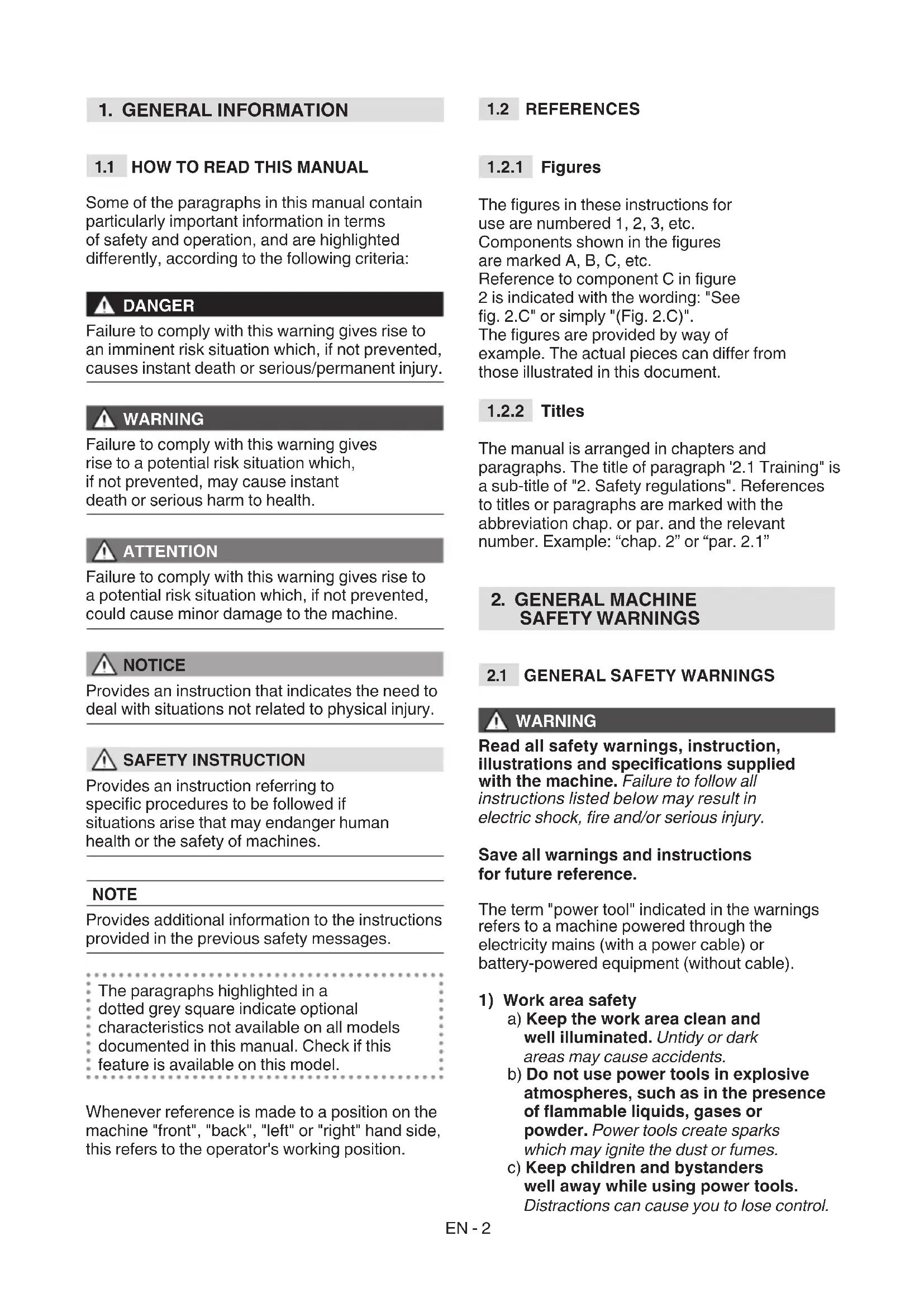
Some of the paragraphs in this manual contain particularly important information in terms of safety and operation, and are highlighted differently, according to the following criteria:

DANGER
Failure to comply with this warning gives rise to an imminent risk situation which, if not prevented, causes instant death or serious/permanent injury.

WARNING
Failure to comply with this warning gives rise to a potential risk situation which, if not prevented, may cause instant death or serious harm to health.

ATTENTION
Failure to comply with this warning gives rise to a potential risk situation which, if not prevented, could cause minor damage to the machine.

NOTICE
Provides an instruction that indicates the need to deal with situations not related to physical injury.

SAFETY INSTRUCTION
Provides an instruction referring to specific procedures to be followed if situations arise that may endanger human health or the safety of machines.
NOTE
Provides additional information to the instructions provided in the previous safety messages.
The paragraphs highlighted in a dotted grey square indicate optional characteristics not available on all models documented in this manual. Check if this feature is available on this model.
Whenever reference is made to a position on the machine "front", "back", "left" or "right" hand side, this refers to the operator's working position.
1.2 REFERENCES
The figures in these instructions for use are numbered 1, 2, 3, etc.
Components shown in the figures are marked A, B, C, etc.
Reference to component C in figure 2 is indicated with the wording: "See fig. 2.C" or simply "(Fig. 2.C)".
The figures are provided by way of example. The actual pieces can differ from those illustrated in this document.
1.2.2 Titles
The manual is arranged in chapters and paragraphs. The title of paragraph '2.1 Training" is a sub-title of "2. Safety regulations". References to titles or paragraphs are marked with the abbreviation chap. or par. and the relevant number. Example: "chap. 2" or "par. 2.1"
2. GENERAL MACHINE SAFETY WARNINGS
2.1 GENERAL SAFETY WARNINGS
WARNING
Read all safety warnings, instruction, illustrations and specifications supplied with the machine. Failure to follow all instructions listed below may result in electric shock, fire and/or serious injury.
Save all warnings and instructions for future reference.
The term "power tool" indicated in the warnings refers to a machine powered through the electricity mains (with a power cable) or battery-powered equipment (without cable).
1) Work area safety
a) Keep the work area clean and well illuminated. Untidy or dark areas may cause accidents.
b) Do not use power tools in explosive atmospheres, such as in the presence of flammable liquids, gases or powder. Power tools create sparks which may ignite the dust or fumes.
c) Keep children and bystanders well away while using power tools. Distractions can cause you to lose control.
2) Electrical safety
a) The battery charging cable plug must match the outlet. Never modify the plug in any way. Do not use any adapter plugs with the earthed (grounded) battery charge cable. Unmodified plugs and matching outlets will reduce the risk of electric shocks.
b) The plug of the electric tool must be compatible with the power socket. Never modify the plug in any way. Do not use adapters with grounded power tools. Unmodified plugs and matching outlets will reduce the risk of electric shocks.
c) Avoid body contact with earthed or grounded surfaces, such as pipes, radiators, cookers and refrigerators. There is an increased risk of electric shock if your body is earthed or grounded.
d) Do not expose power tools to rain or wet environments. Water entering a power tool will increase the risk of electrical shock.
e) Never pull on the cord to remove the plug from the socket. Keep the battery charge cable away from heat, oil, solvents, sharp objects, sharp edges or moving parts. Damaged or entangled cords increase the risk of electric shocks.
f) Do not use the cable improperly.
Do not use the cable to carry, pull or disconnect the tool from the socket. Keep the cable away from heat, oil, sharp edges or moving parts. Damaged or entangled cords increase the risk of electric shocks.
g) When using the power tool outdoors, use an extension cable suitable for outdoor use. Using an extension cable suitable for outdoor use reduces the risk of electric shock.
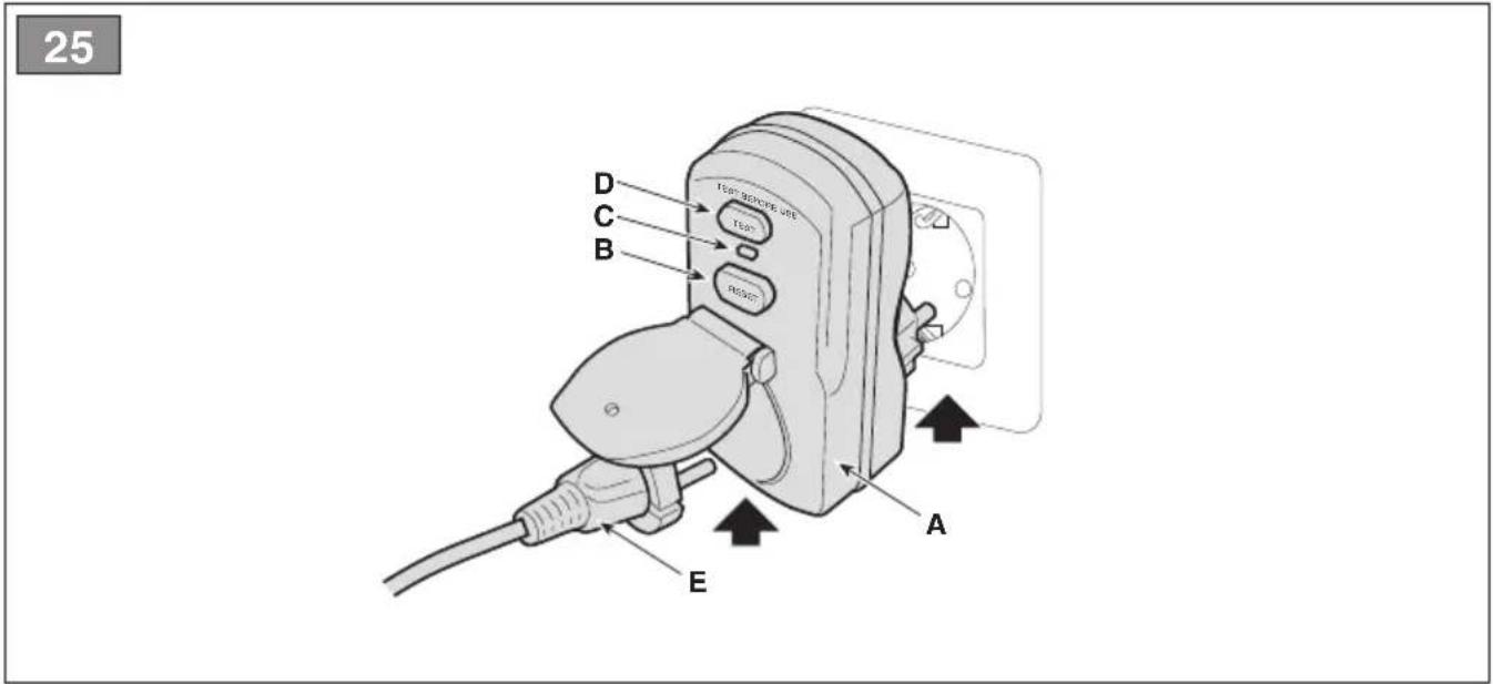
h) If using a power tool in a humid environment cannot be avoided, use a power outlet protected by a residual current device (RCD). Using an RCD reduces the risk of electric shock.
i) Only connect the battery charger to a socket with the mains frequency as indicated on the name plate.
DANGER
Moisture and electricity are not compatible:
- Make sure your hands are dry when handling and connecting the electrical cables.
- Never connect an electrical socket or a cable in a wet area (presence of puddles or damp terrain).
- If necessary, use an extension cord with integrated watertight and type-approved sockets, available on the market.
- The pre-installation of a charging socket, connected to the mains power network of the building must be carried out by a qualified electrician and must be suitably protected by a differential (RCD-Residual Current Device) with a release current compliant with legislation in force.
- Incorrect connection can cause short circuits and serious personal injury, including death.
• To prevent interruptions in the supply of electrical power during charging operations:
- check that the overall capacity of the electrical system is suitable.
- connect the machine to a power socket with sufficient amperage.
- avoid simultaneous use of other electrical appliances with high energy draw.
3) Personal safety
a) Stay alert, check what you are doing and use common sense when using a power tool. Do not use the power tool when you are tired or under the influence of drugs, alcohol or medicines. A moment of inattention while operating a power tool may result in serious personal injury.
b) Use personal protective equipment (PPE). Always wear eye protection. Using protective equipment such as a dust mask, non-slip safety shoes, hard hat or hearing protection helps prevent personal injuries.
c) Avoid unintentional starting. Make sure that the switch is in the "OFF" position before inserting the plug, holding or carrying the electric power tool. Carrying an electric tool with your finger on the switch or connecting to the mains socket with the switch in the "ON" position makes accidents more likely.
d) Remove any adjustment spanner or tool before switching the power tool on. A wrench or a tool left attached
to a rotating part of the machine may result in personal injury.
e) Do not lean out. Keep proper footing and balance at all times.
This ensures better control of the power tool in unexpected situations.
f) Dress appropriately. Do not wear loose clothes or jewellery. Keep hair and clothing away from moving parts. Loose clothes, jewellery or long hair can be caught in moving parts.
g) If devices have to be connected to powder extraction and collection systems, make sure they are connected and used appropriately. Using these devices may reduce powder-related hazards.
h) Do not allow familiarity acquired while using the machine to become complacent and ignore the safety principles of the power tool. A careless action can cause severe injury in a fraction of a second.
4) Using and looking after power tools
a) Do not over-charge the power tool. Use a power tool appropriate for the task in question. The correct power tool will do the job better and safer at the speed for which it was designed.
b) Do not use the power tool if the switch does not turn it on and off. Any power tool that cannot be controlled with the switch is dangerous and must be repaired.
c) Do not use the machine if the key ignition switch does not turn it on and off. A machine which cannot be controlled with the key switch is dangerous and must be repaired at an Authorised Service Centre.
d) Remove the ignition key before making any adjustments, changing accessories, or before putting the power tool away. These preventive safety measures reduce the risk of accidental start-up of the power tool.
e) Store unused power tools out of the reach of children and do not allow persons who are not familiar with using the machine and these instructions to use it. Power tools are dangerous in the hands of untrained users.
f) Ensure regular maintenance of power tools and accessories. Check for misalignment or binding of moving parts, breakage of parts and any
other condition that may affect power tool operation. In case of damage, the power tool must be repaired before it can be used. Many accidents are caused by poor maintenance.
g) Keep cutting tools sharp and clean.
Properly maintained cutting tools with sharp cutting edges are less likely to bind and are easier to control.
h) Use the power tool and its accessories in accordance with these instructions, taking into account the working conditions and the task to be performed. Using the power tool for operations other than those intended could result in a hazardous situation.
i) Keep handles and grasping surfaces dry, clean and without any trace of oil or grease. Slippery grips and gripping surfaces do not allow safe movement and control of the tool in unexpected situations.
a) Only use battery chargers recommended by the manufacturer to recharge batteries. A battery charger suitable for one type of battery pack can create a risk of fire, electric shock, overheating or leakage of corrosive battery fluid when used with another battery pack.
b) Use only batteries specifically designed for your power tool. Use of any other battery packs may create a risk of injury and fire.
c) When the batteries are not in use, they should be kept away from other metal objects such as paper clips, coins, keys, nails, screws or other small metal objects that could short-circuit the contacts. Short circuits between battery contacts can lead to explosion or fires.
d) A battery in poor condition may allow fluid to leak from it. Avoid contact with battery fluids. In case of accidental contact, rinse with water. If battery fluids come into contact with the eyes, also consult a doctor. Liquid leaked from the battery may cause skin irritation or burns.
e) Do not use a machine or battery pack that are damaged or modified. Damaged or modified batteries may
exhibit unpredictable behaviour resulting in fire, explosion or risk of injury.
f) Do not expose the battery pack or the tool to fire or excessively high temperatures. Exposure to fire or temperatures exceeding 70^ C may cause an explosion.
g) Follow all the charging instructions and do not charge the battery pack or tool outside the temperature range specified in the instructions. Improper charging or at temperatures outside the specified range can damage the batteries and increase the risk of fire.
h) Do not charge the battery pack in places with vapours or flammable substances present or in rooms which are damp. If it is not possible to avoid damp environments, use a power socket protected by a differential switch (RCD-Residual Current Device) to reduce the risk of electric shocks.
i) Keep the battery charge cable out of the reach of children.
6) Technical Assistance
a) Have your power tool serviced by a qualified repair person using only identical replacement parts. This will ensure that the safety of the power tool is maintained.
b) Do not carry out repairs on the battery. Repairs must be carried out by the manufacturer or by a specialized service centre.
3. SAFETY WARNINGS FOR RIDE-ON LAWN MOWER WITH SEATED OPERATOR
3.1 TRAINING
- Become acquainted with the controls and the proper use of the machine. Learn how to stop the machine quickly.
- Never allow the machine to be used by children or individuals who are not familiar with the instructions. Local laws may establish a minimum age for users.
- Do not allow children or other passengers to ride on the machine.
- Bear in mind that the user is responsible for accidents or unexpected events occurring to other people or their property.
It is the user's responsibility to assess the potential risk of the area where work is to be carried out and to take all the necessary precautions to ensure his own safety and that of others, particularly on slopes or rough, slippery and unstable ground.
- This manual is an integral part of the machine and therefore must always be accompany it in the case of temporary or definitive transfer.
3.2 PRELIMINARY OPERATIONS
Personal Protective Equipment (PPE)
- Wear suitable clothing, strong work shoes with anti-slip soles, and long pants. Do not operate the machine barefoot or wearing open sandals. Wear hearing protection devices.
- Use of hearing protections can reduce the ability to hear any warnings (shouting or alarms). Be careful of what occurs around you in the work area.
- Never wear scarves, shirts, necklaces, bracelets, loose flowing clothing, laces or ties or any hanging or flapping accessory that could catch in the machine or in any objects or materials in the work area.
- Tie up long hair.
Work / Machine Area
Thoroughly inspect the entire work area and remove anything that could be thrown by the machine or damage the cutting means/rotating units (stones, branches, iron wire, bones, etc.).
3.3 DURING OPERATION
Work Area
- Do not use the machine in environments that pose the risk of explosion, in the presence of flammable liquids, gases or powders. Electrical contact or mechanical rubbing can generate sparks that can ignite powder or vapour.
- Work only in daylight or with good artificial light in good visibility conditions.
- Keep people, children and animals away from the work area. Children must be supervised by another adult.
- Avoid working with wet grass, in the rain and when there is a risk of a thunderstorm, and especially of lightning.
- Pay careful attention to uneven ground (hills, dips), slopes, hidden hazards and obstacles that could limit visibility.
- Be very careful near ravines, ditches or embankments. The machine could overturn if a wheel slides over the edge or if the earth gives way.
- Pay close attention on sloping ground which requires special care to prevent overturning or loss of control of the machine. The main reasons for loss of control are:
- Insufficient wheel grip.
- Excessive speed.
- Sharp changes of direction.
- Inadequate braking.
- Type of machine unsuitable for its task.
- Lack of awareness of the effect of ground conditions.
• Using the machine for towing.
- Look out for traffic when using the machine near the road.

NOTICE
The machines detailed in this manual are not designed for use as towing vehicles.
Conduct
- When working behind the wheel, do not become distracted and maintain the required level of concentration.
- Exercise caution when reversing or moving backwards. Look behind you to make sure there are no obstacles before and during operations in reverse gear.
- Pay careful attention when using the attachments that can alter the stability of the machine, especially on slopes.
- Always keep hands and feet away from the cutting means, when starting and when using the machine.
- Keep hands and feet away from the seat support. There is the risk of crushing injuries.

WARNING
the cutting means will continue to rotate for a few seconds after disengagement or after switching off the motor.

WARNING
Pay attention to the cutting means assembly with more than one cutting element, since one rotating cutting means can trigger rotation of the others.

SAFETY INSTRUCTION
If something breaks or an accident occurs during work, turn off the motor immediately and move the machine away to prevent further damage; if an accident occurs with injuries or third parties are injured, carry out the first aid measures most suitable for the situation immediately and contact the medical authorities for any necessary health care. Carefully remove any debris which could cause damage or injury to persons or animals if ignored.
Restrictions of use
- Never operate the machine with guards damaged, missing or incorrectly assembled (grass catcher, side discharge guards rear discharge guards)
- Don't use the machine if the attachments/tools are not installed in their seats.
- Never disengage, deactivate, remove or tamper with the safety systems/micro switches installed.
- Do not strain the machine too much and do not use an inappropriate machine for heavy-duty work; if you use the correct machine, you will reduce the risk of hazards and improve the quality of your work.
- The machine has not been approved for use on public roads. It must be used (as indicated by the highway code) in private areas closed to traffic.
3.4 MAINTENANCE, STORAGE
Ensure regular maintenance and correct storage to maintain machine safety and high performance levels.
Maintenance
- Never use the machine with worn or damaged parts. Faulty or worn-out parts must always be replaced and never repaired.
- Be careful during adjustment of the machine to prevent entrapment of the fingers between moving parts of the cutting means and fixed parts of the machine.
- Have your machine serviced by a qualified repair person using only identical replacement parts. This will ensure that the safety of the machine is maintained.
- Do not carry out repairs on the battery. Repairs must be carried out by the manufacturer or by a specialized service centre.

SAFETY INSTRUCTION
The noise and vibration levels shown in these instructions are the maximum levels when using the machine. The use of an unbalanced cutting element, the excessive speed of movement, or the absence of maintenance have a significant influence on noise emissions and vibrations. Consequently, it is necessary to take preventive steps to eliminate possible damage due to high levels of noise and stress from vibration; maintain the machine well, wear ear protection devices, and take breaks whilst working.
Storage
To reduce fire risks, do not leave containers with debris inside a room.
3.5 ENVIRONMENTAL PROTECTION
Protecting the environment must be a significant and top priority for machine use, to the benefit of civil co-habitation and of the environment that we live in.
- Scrupulously comply with local regulations for the disposal of packaging, deteriorated parts or any elements with a strong environmental impact; this waste must not be disposed of with regular waste, but must be separated and taken to collection centres, which will recycle the materials.
- Comply with local regulations for the disposal of waste materials.
- When the machine is withdrawn from service, do not dispose of it in the environment, but take it to a waste disposal facility in accordance with the local regulations in force.

Do not throw electrical equipment away with domestic waste. In observance of European Directive 2012/19/EU on electrical and electronic equipment waste and its implementation, in observance of UK Regulation “The waste electrical and electronic equipment regulations 2013 (as amended)” and in accordance with national regulations, old electrical equipment must be collected separately, for eco-compatible recycling. If electrical equipment is disposed of in dumps or in
landfills, hazardous substances can leak into the groundwater and contaminate the food chain, damaging your health and well-being. For further information on the disposal of this product, contact your dealer or a domestic waste collection service.
Li-ion
At the end of their working life, dispose of batteries with all due care and in compliance with applicable local legislation. Batteries contain materials classified as hazardous for people and the environment. They must be removed and disposed of separately at a facility that accepts lithium-ion batteries.

Separate waste collection of the products and packaging used allows the materials to be recycled and reused. Reuse of recycled materials help to prevent environmental pollution and reduces the demand for raw materials.
4. ABOUT THE MACHINE
4.1 MACHINE DESCRIPTION AND INTENDED USE
This machine is a ride-on lawn mower with seated operator.
The machine is equipped with an electric motor that drives the cutting means and an electric drive motor. The machine has rear-wheel drive.
The operator is able to operate the machine and use the main controls, always seated in the operator's position.
The safety devices installed on the machine will disengage the engine and cutting means in a couple of seconds (par. 7.2.2).
4.1.1 Intended use
This machine was designed and built to cut grass.
In particular, the models:
- MP 84 Li 48 Series V1/V2 and MP 98 Li 48 Series V3 can:
-
mow the grass and collect it in the grass catcher;
-
mow the grass and discharge it on to the ground through the rear part (if available).
- mow the grass, chop it and discharge it on the ground (mulching effect, if available). The models:
• SD 98 Li 48 Series V1/V2 and SD 108 Li 48 Series V3 can:
1. mow the grass and deposit it on the ground laterally.
2. mow the grass, chop it and discharge it on the ground (mulching effect, if available).
The use of special attachments provided for by the Manufacturer as original equipment or which may be purchased separately, allows this work to be done in various operating modes, illustrated in this manual or the instructions that accompany the single attachments. Likewise, the intended use can be extended to include other functions by applying supplementary attachments (if provided for by the Manufacturer), abiding by the restrictions and conditions indicated in the instructions accompanying the attachment.
4.1.2 Improper use
Any use other than those mentioned above may be hazardous and cause harm to persons and/or damage things. Examples of improper use may include, but are not limited to:
- Allowing children, animals or other passengers on the machine as they could fall off and injure themselves or compromise safe driving by the operator;
- push loads;
- using the machine for riding over unstable, slippery, icy, stony, rough, marshy ground or puddles that do not allow the consistency of the ground to be assessed;
• Using the cutting means on surfaces other than grass;
• using of the machine for leaf or debris collection.
NOTICE
Improper use of the machine will void the warranty and relieves the Manufacturer of any liability, placing all responsibility for damage or injury, to him/herself or third parties, on the user.
4.1.3 Type of users
This machine is intended for use by consumers, i.e. non-professional operators. It is intended for "hobby use" and must be only used by a single operator.
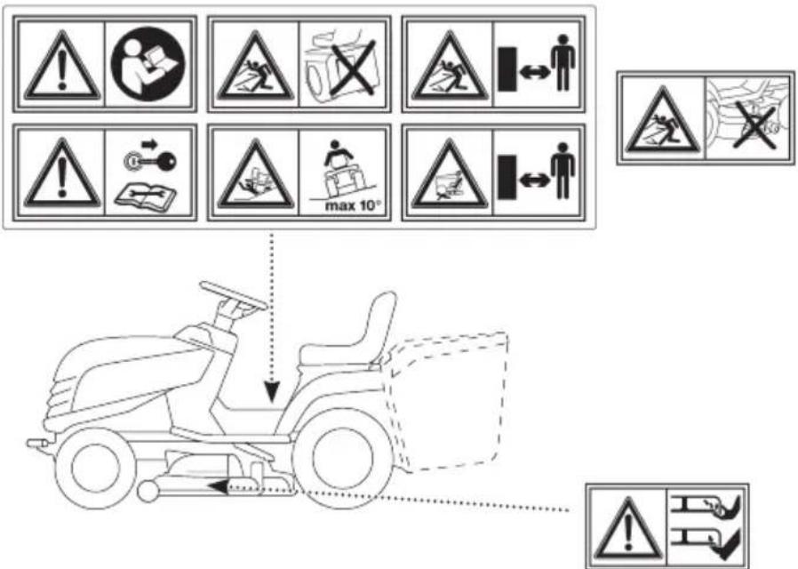
4.2 SAFETY SIGNS
The machine has various symbols on it (fig. 2). Their function is to remind the operator of the correct conduct for use, with due care and caution.
Meanings of the symbols:
ATTENTION
Read the instructions before use.
ATTENTION
Remove the key and read the instructions before carrying out any maintenance or repair work.
HAZARD OF EJECTED OB- JECTS.
Do not operate without either the rear discharge guard or the grass catcher being in place. (for models with rear collection system only).
HAZARD OF EJECTED OB- JECTS.
Do not work without having fitted the side discharge chute. (only for models with side discharge)
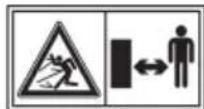
HAZARD OF EJECTED OB- JECTS.
Keep all persons away and outside the work area during machine use.
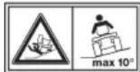
RISK OF MACHINE ROLL-OVER:
Do not use the machine on gradients in excess of 10^ .
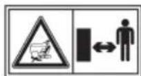
CRUSHING HAZARD
Make sure that children remain at a safe distance from the machine when it is running.
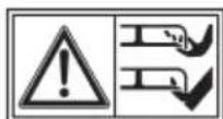
CUTTING HAZARD
Cutting means in operation.
Do not insert hands or feet into the cutting means housing.
SAFETY INSTRUCTION
Any damaged or illegible decals must be replaced. Order replacement decals from an Authorised Service Centre.
4.3 IDENTIFICATION LABEL
The identification label includes the following data (fig. 1):
- Sound power level.
- Conformity marking.
- Year of manufacture.
- Type of machine.
- Serial number.
- Name and address of Manufacturer.
- Article code.
- Max. motor operation speed.
- Weight in kg.
- Electrical protection rating.
- Rated voltage.
- Battery capacity.
Write the identification data of the machine in the specific space on the label on the back of the cover page.

SAFETY INSTRUCTION
State the identification data on the product identification label whenever you contact an Authorised Service Centre.
NOTE
An example of the Declaration of Conformity is provided on the last pages of this manual.
4.4 MAIN COMPONENTS
The machine comprises the following main components having the following functions (Fig.1):
A. Cutting means assembly: this is the assembly comprising the casing housing the rotating cutting means assembly and the cutting means.
B. Cutting means: these are what cut the grass; the fins at the ends help convey the cut grass towards the discharge chute.
C. Side discharge chute: it is a safety protection and prevents any objects collected by the cutting means from being thrown away from the machine (only for models with side discharge).
D. Discharge chute: this is the part connecting the cutting means assembly to the grass catcher (for models with rear collector only).
E. Grass catcher: in addition to collecting the mown grass, the grass catcher also constitutes a safety element, since it prevents any objects picked up by the cutting means from being projected long distance from the machine (for models with rear collector only).
F. Rear discharge guard (available upon request): this can be fitted in place of the grass catcher and prevents objects from being drawn up by the cutting means and hurled away from the machine (for rear collection models only).
G. Driving seat: this is where the machine operator sits. It has a sensor connected to safety devices for detecting the presence of the operator.
H. Blade motor: drives the cutting means.
I. Drive motor: drives the wheels.
J. Battery: provides power to the motor and all electrical components of the machine.
K. Front bumper: this protects the front section of the machine.
L. Steering wheel: turns the front wheels.
M. Pushbutton panel : interface comprising all the main commands for using the machine.
5. ASSEMBLY

WARNING
The safety regulations to follow are described in chap. 2. Strictly comply with these instructions to avoid serious risks or hazards. Do not use the machine until all the instructions provided in the “ASSEMBLY” section have been carried out.
For storage and transport purposes, some components of the machine are not installed in the factory and have to be assembled after unpacking.
Unpacking and completing the assembly should be done on a flat and stable surface, with enough space for moving the machine and its packaging, always making use of suitable equipment.
5.1 ASSEMBLY COMPONENTS
The packaging holds the components needed for assembly as listed in the table below:
| Description |
| 1 Steering wheel |
| 2 Dashboard cover and steering wheel assembly parts |
| 3 Driving seat |
| 4 Battery charger |
| 5 Front bumper |
| 6 Ant-scalping wheels |
| 7 Grass catcher with relative mounting screws and relative instructions (only for models with rear grass catcher) |
| 8 Lower part of the rear plate, the grass catcher bag supports and relative attachment and fitting accessories (only for models with rear grass catcher) |
| 9 Side discharge chute (for models with side discharge only) |
| 10 Side reinforcements of the cutting means assembly (for models with side discharge only, if available) |
| 11 Envelope containing:- the instruction manuals and documents- driving seat assembly screws- side discharge chute assembly fittings (for models with side discharge only)- 2 starter keys |
| 12 Mobile phone holder kit (if provided) |
5.1.1 Unpacking
- Carefully open the packaging, paying attention not to lose components.
- Consult the documentation in the box, including these instructions.
- Remove all the unassembled parts from the box.
- Remove the machine from the packaging taking the following precautions:
- move the cutting means assembly to its maximum height (par. 6.4) to protect it against damage when the machine is lifted off the base pallet;
- Move the front drive release lever to the released position (par. 6.3);
- Lift the machine off the base pallet.
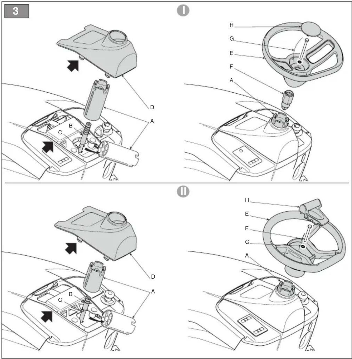
5.2 STEERING WHEEL ASSEMBLY
- Put the machine on a flat surface and straighten the front wheels.
- Fit the hub (fig. 3.A) on the steering shaft (fig. 3.B) making sure that the pin (fig. 3.C) is correctly inserted into its seat in the hub.
- Replace the cap on the dashboard (fig. 3.B) inserting the five fittings so they click into place.
- Fit the steering wheel (fig. 3.E) on the hub (fig. 3.A) with the spokes pointing towards the seat.
5a. Only for steering wheel of type "I"
- Insert the spacer (fig. 3.F) and fix the steering wheel using the supplied screws (fig. 3.G) in the indicated sequence.
5b. Only for steering wheel of type "II" - Fix the steering wheel using the supplied screws (fig. 3.F, 3.G) in the indicated sequence.
6a. Only for steering wheel of type "I" - Apply the steering wheel cover (fig. 3.H) inserting with a click into its seat.
6b. Only for steering wheel of type "II" - Apply the mobile phone cover (fig. 3.H) inserting with a click into its seat.
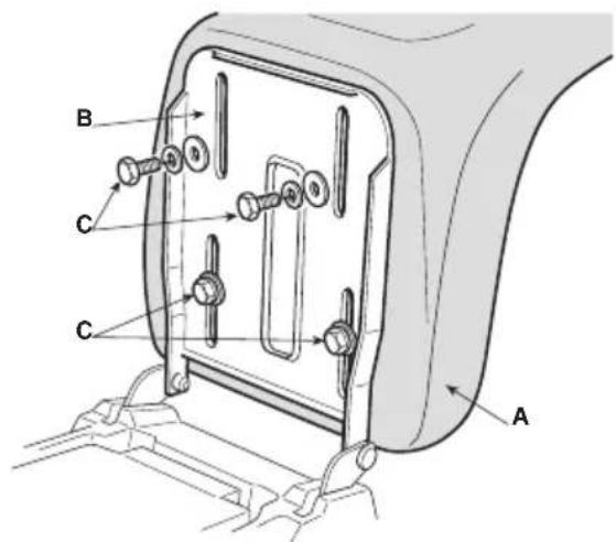
5.3 SEAT ASSEMBLY
Fit the seat (fig. 4.A) on the plate (fig. 4.B) using the screws (fig. 4.C).
5.4 MOUNTING THE REAR BUMPER
1a. Only for bumper of type "I" - Fit the front bumper (fig. 5.A) on the lower part of the frame (fig. 5.B) using the four screws (fig. 5.C).
1b. Only for bumper of type "II"
-
Fit the two supports (fig. 5.A) and (fig. 5.B) on the lower part of the frame (fig 5.C) observing the fitting order indicated in the figure R= right; L= left.
-
Fully tighten the screws (Fig. 5.D).
-
Fix the front bumper (fig. 5.E) to the supports (fig. 5.A) and (fig. 5.B) using the screws (fig. 5.F) and nuts (fig. 5.G).
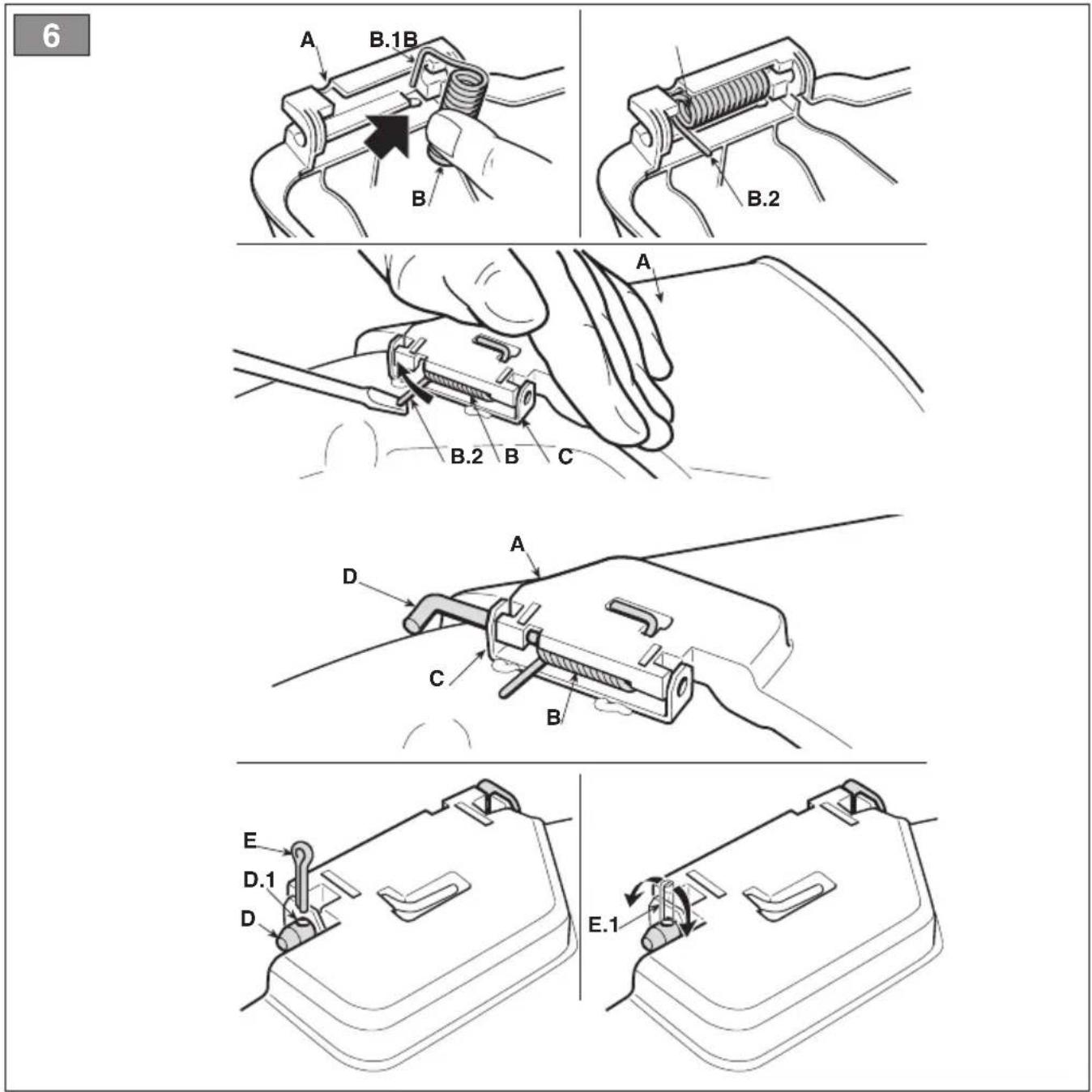
5.5 SIDE DISCHARGE CHUTE ASSEMBLY (FOR MODELS WITH SIDE DISCHARGE ONLY)
- From the inside of the side discharge chute (fig. 6.A), fit the spring (fig. 6.B) by inserting the terminal (fig. 6.B.1) into the
hole and turning it so that both the spring (fig. 6.B) and the terminal (fig. 6.B.2) are securely positioned in their housings.
- Position the side discharge chute (fig. 6.A) in line with the cutting means assembly brackets (fig. 6.C). Using a screwdriver, turn the second terminal (fig. 6.B.2) of the spring (fig. 6.B) to bring it outside the side discharge chute.
- Fit the pin (fig. 6.D) in the holes on the brackets (fig. 6.C) and on the side discharge chute, so that it passes through the coils of the spring (fig. 6.B) and the drilled end comes out of the inner most bracket.
- Insert the cotter pin (fig. 6.E) into the hole (fig. 6.D.1) on the pin (fig. 6.D) and rotate the pin in order to bend the two ends (fig. 6.E.1) of the cotter pin, (with the aid of a pair of pliers), so that it cannot slide out, causing the pin (fig. 6.D) to disengage.

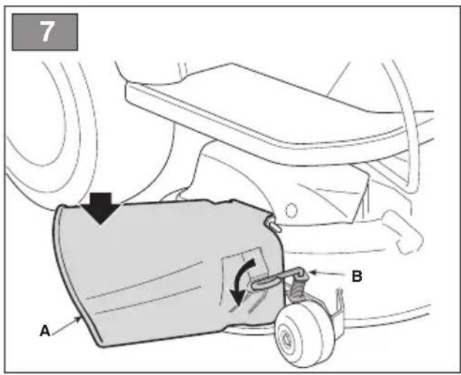
WARNING
Check that the spring works correctly and keep the side discharge chute securely lowered. Make sure that the pin is fitted properly to prevent it from falling out accidentally. make sure that the side discharge guard (Fig. 7.A) is lowered and locked with the safety lever (Fig. 7.B).

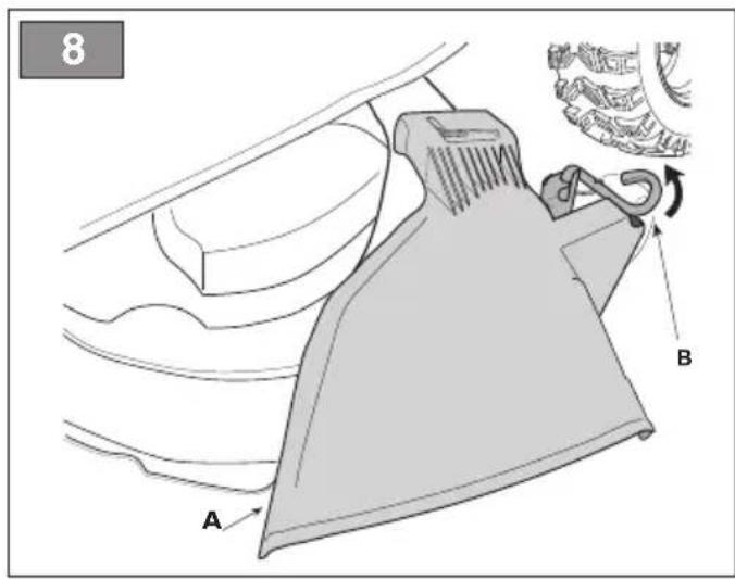
ATTENTION
Before disassembling or servicing the deflector, always push the safety lever (Fig. 8.B) and lift the side unloading guard (Fig. 8.A) to allow disassembly.
NOTE
To remove the deflector, perform assembly steps in reverse order.
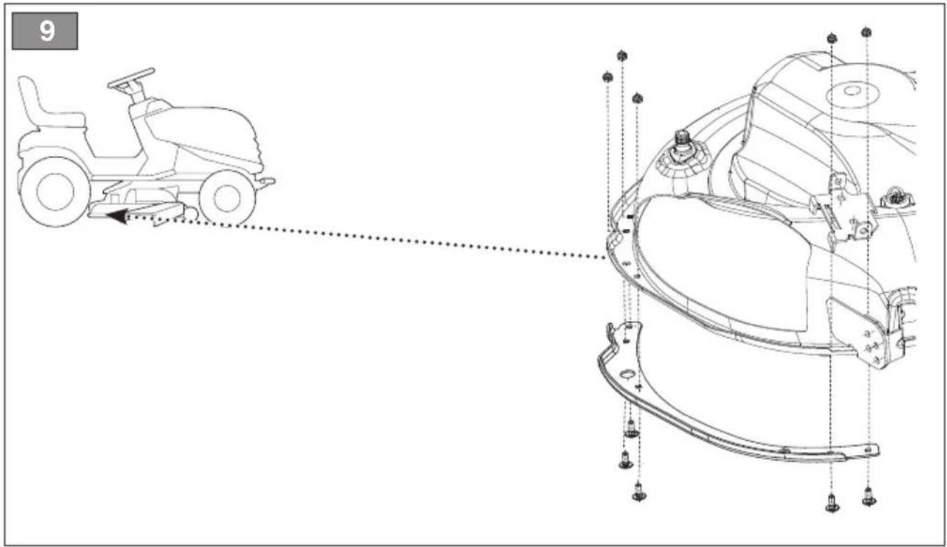
5.6
FITTING OF THE SIDE REINFORCEMENTS OF THE CUTTING MEANS ASSEMBLY (FOR MODELS WITH SIDE DISCHARGE ONLY, IF AVAILABLE)
Finish the fitting cutting means assembly mounting the side reinforcements on the profile of the cutting means assembly using the relative screws (fig. 9)
5.7
MOUNTING AND COMPLETING OF THE REAR PLATE (ONLY FOR MODELS WITH REAR GRASS CATCHER)
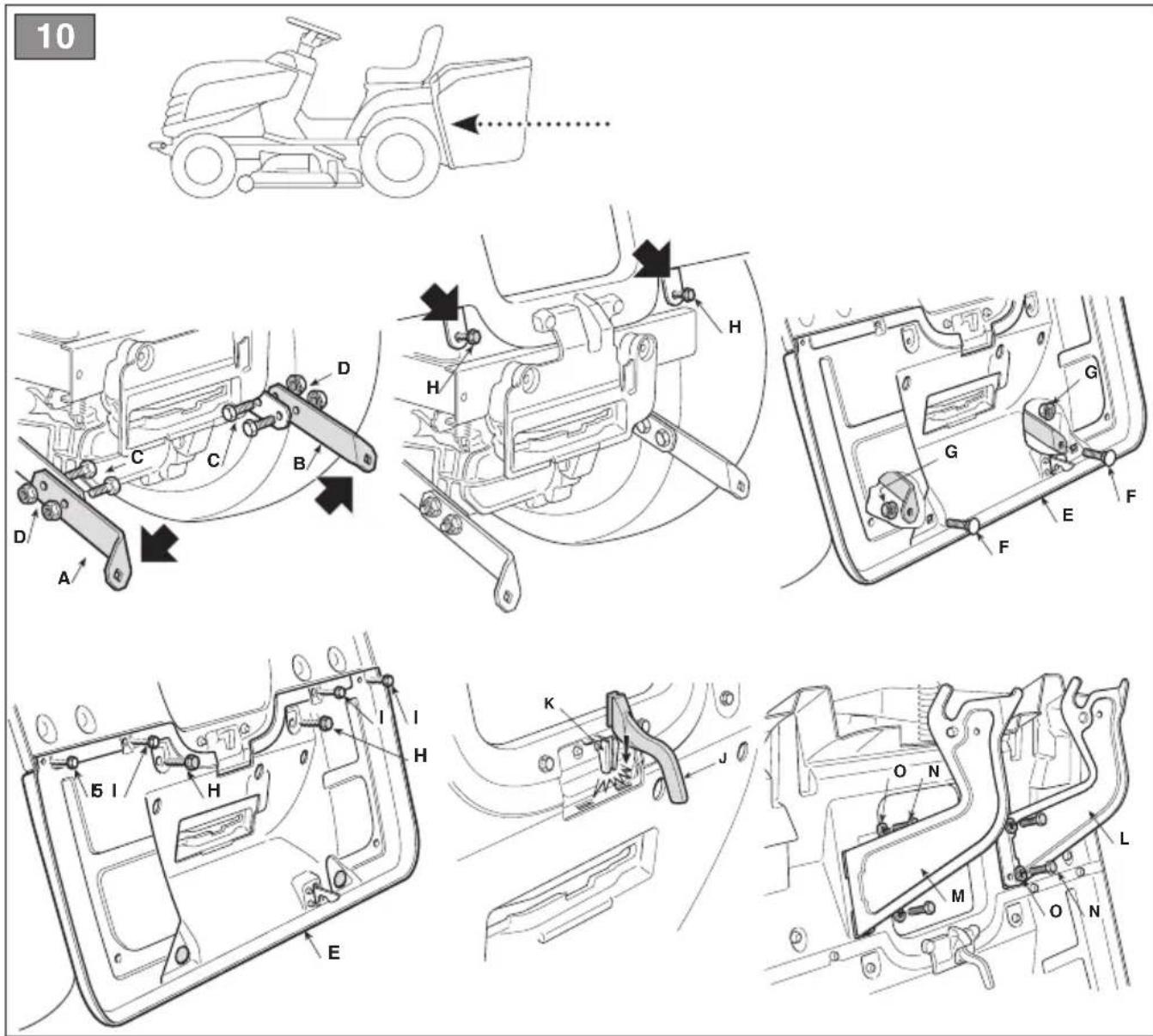
- Fit the two lower brackets (fig.10.A) and (fig.10.B), respecting the assembly direction indicated in the figure, fix them with the screws (fig.10.C) and nuts (fig.10.D), tightening them fully.
- Remove the two screws (fig. 10.H), which will be used later.
- Fit the lower part (fig. 10.E) of the rear plate and fix it to the lower brackets with the screws (fig. 10.F) and nuts (fig. 10.G), without tightening them completely.
- Complete the fastening of the lower part (fig.10.E) of the rear plate by fully tightening the two central screws (fig.10.H) previously removed and the four upper screws (fig.10.I)
- Fully tighten the two lower nuts (fig. 10.G).
- Insert the lever (fig. 10.J) of the full collection bag indicator in its seat (fig. 10.K) and push it down until a click is heard.
- Fit the two supports of the grass catcher (fig.10.L) and (fig.10.M), respecting the assembly sequence indicated in the figure, and fix them with the screws (fig.10N) and spring washers (fig. 10.O), tightening them fully.
5.8
MOUNTING OF THE GRASS CATCHER (ONLY FOR MODELS WITH REAR GRASS CATCHER) (ONLY FOR MODELS OF TYPE "III")
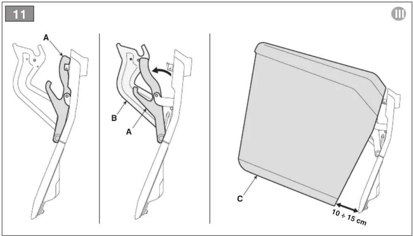
- Use the grass catcher open / close buttons (fig. 13.U, V) to align the two-cam lever (fig. 11.A) with the supports (fig. 11.B) of the grass catcher.
NOTE
To carry out the alignment, and then manually adjust the position of the two-cam lever (fig.11.A), it is necessary to keep the opening (fig.13U) or closing (fig.13V) button of the grass catcher pressed.
-
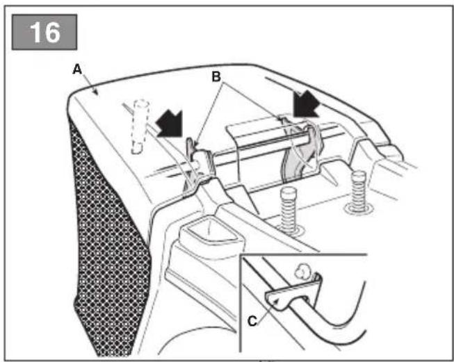
Hook the grass catcher (fig. 16.A) to the supports (fig. 16.B) and centre it with respect to the rear plate. Centring is ensured by using the right support as a lateral support.
-
Close the grass catcher (fig. 11.C) by keeping the collection bag closing button pressed (fig. 13.V).
NOTE
To remove the grass catcher (fig. 11.C), lift it in such a way as to maintain a distance from the plate of about 10 ÷ 15 cm, as shown in fig. 11.
6. CONTROLS
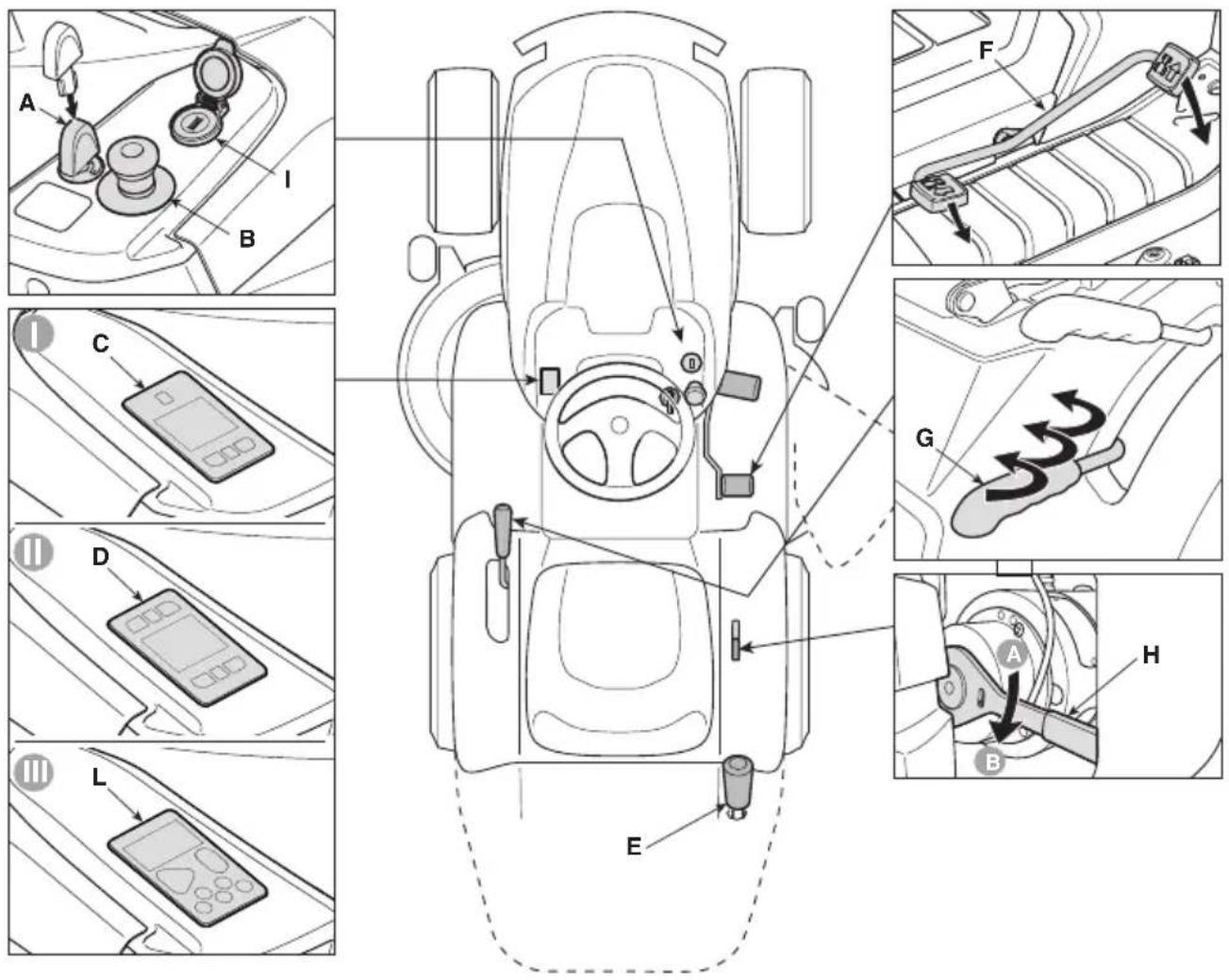
6.1 KEY IGNITION SWITCH
This key-operated command serves as the main switch to enable or dis-enable the machine's ignition circuit. The key-operated switched (fig. 12.A) has 2 positions:
- Key removed. The power circuit is disabled and the machine turns off. No function can be activated.
- Key fully inserted. the machine is ready to be turned ON.
6.2 DRIVE PEDAL
The drive pedal (Fig. 12.A.) activates wheel drive and adjusts machine speed in forward and reverse gears.
- Forward drive gear: by pressing the pedal forwards, the machine advances. Increasing the pressure on the pedal progressively increases the speed of the machine.

- Reverse drive gear: by pressing the pedal backwards, the machine moves in reverse gear. Reducing the pressure on the pedal progressively reduces the speed of the machine.
- Parking: when the pedal is released, a service brake engages automatically which serves to decelerate and stop the machine, preventing any additional movement until the drive pedal is once again pressed.
NOTE
The drive pedal deactivates when the operator leaves the seat;
6.3 TRANSMISSION ENGAGEMENT / DISENGAGEMENT LEVER
The transmission engagement/disengagement lever (Fig. 12.E) allows the machine to be moved manually (pushed or towed) without having to switch on the machine. This command has two positions, indicated by the following symbols:

- Drive engaged : move the lever (fig. 12.H) into the horizontal position (A). The machine can be moved normally by starting the machine.

- Transmission disengaged: move the lever (fig. 12.H) downwards (B). The machine can be moved manually without having to start the machine.
WARNING
Only move the machine manually on a level surface.
SAFETY INSTRUCTION
The engagement/disengagement lever must never be in the intermediate position. This condition will cause overheating and damage the transmission.
6.4 CUTTING HEIGHT ADJUSTMENT
6.4.1 Adjustment lever (only for models of type "I" and "II")
This lever (fig. 12.G) is used to raise and lower the cutting means assembly, which may be positioned at 7 different cutting heights.

The seven positions for this lever, shown as «1» to «7» on the label, correspond to various cutting heights between 3 and 8 cm.

To move from one position to another, the lever must be moved sideways and repositioned in one of the stop notches.

These buttons are used to raise (fig. 13.S) and lower (fig. 13.T) the cutting means assembly, which may be positioned at 7 different cutting heights.

The seven positions are graphically indicated on the display (fig. 13.W) and correspond to the same number of cutting heights between 3 and 8 cm.
To move from one position to another, press the adjustment buttons (fig. 13.S, fig. 13.T) until the desired position is reached. Alternatively, by holding down one of the two adjustment buttons, it is possible to change the height of the cutting assembly continuously up to the desired position.
NOTE
If the key is fully inserted (fig.12.A), pressing the reverse button (fig.13.C) together with the lifting (fig.13.S) or lowering (fig.13.T) buttons, it is possible to raise or lower the cutting means assembly even when the driver is not seated on board.
The emergency button (Fig. 12.B) allows the machine to be stopped immediately in the event of an emergency.
The button has two positions:

- Activated: pressing the emergency button stops the cutting means motors and drive control devices.

- Deactivated: turn the emergency button clockwise to deactivate it and restore all functions. To start the machine, repeat the starting procedure using the key (par.7.4).
NOTE
The machine cannot be started when the emergency button is activated.

NOTICE
The emergency button should never be used as a routine method for stopping the machine.
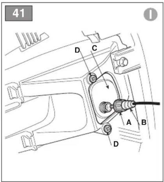
6.6 AUXILIARY SOCKET FOR USB ACCESSORIES
This socket (fig. 12.1) can charge USB devices. It only has a recharging function. The socket has no communication function with the connected USB device.
The socket is only live when the key (fig. 12.A) is fully inserted.
Do not recharge the accessory connected to the USB socket in rainy, humid or high temperature conditions with direct exposure to sunlight. Use in these conditions invalidates the warranty and waives the Manufacturer from any liability in the event of problems.
Do not open the USB plug in rainy or dusty areas.
The Manufacturer declines any and all liability in the event of damage to the accessory connected to the USB socket or loss of data during its use.
6.7 WARNING BUZZERS
- A double buzzer signal indicates that the grass catcher has not been fitted. Check the presence or correct assembly of the grass catcher (only for models with rear grass catcher).
- A continuous buzzer signal indicates that the grass catcher is full. Empty it (see par. 7.5.4) (only for models with rear grass catcher).
- A single buzzer signal indicates the lack of consent for reverse cutting. See icon fig. 13.C.
- The emission of an intermittent sound signal indicates that the key is inserted but the machine has not been started within a few minutes of its insertion.
6.8 TIPPING LEVER FOR GRASS CATCHER (IF AVAILABLE, ONLY FOR MODELS WITH REAR GRASS CATCHER)
This lever, removable from its seat, allows the grass catcher to be overturned for emptying, reducing the effort required by the operator (fig. 12.E).
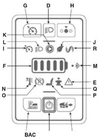
Depending on the model, the machine can be equipped with one of the pushbutton panel versions (fig. 12.C, fig. 12.D and fig. 12.L) described below: :

With the key fully inserted this button (fig. 13.A) turns the machine ON and enables all functions.
NOTE
If all safety conditions are met, the "READY" icon comes ON (fig. 13.K) and the machine is ready to be used (see par. 7.4).

Press the button fig. 13.B to engage/disengage the cutting means.
- When the cutting means are engaged, they become operational after a few seconds.
- When the cutting means are disengaged, a brake is applied simultaneously to stop them rotating after a few seconds.
NOTE
If the cutting means are engaged without taking the necessary safety precautions, the machine shuts down and cannot be restarted (see par. 7.2.2)

Holding down the button fig. 13.C gives consent for reverse mowing.
For reverse cutting, engage the cutting means and simultaneously hold down the button.
NOTE
A single buzzer signal indicates the lack of consent for reverse cutting.

Pushing the button fig. 13.D turns the beacon on/off.
When the beacons are ON, icon fig. 13.L is illuminated

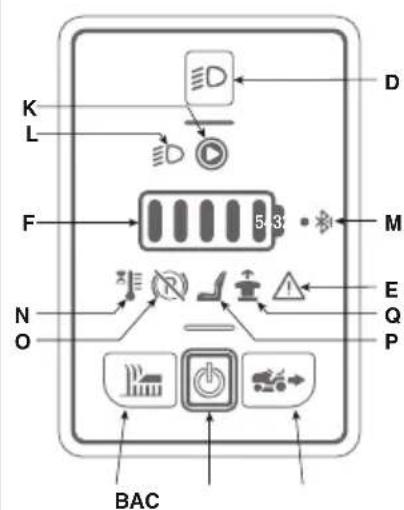
Attention icon
If icon fig. 13.E is illuminated, it this indicates failure to comply with safety conditions or a possible malfunction of the machine (see chap. 15).

Battery LED
The LEDs fig. 13.F generally indicate the charge level of the machine's batteries but in particular combinations their lighting status provides information about machine malfunctions (see chap. 15).

"Ready" icon
The icon in fig. 13.K is illuminated when the machine is ON and ready to be used.

"Bluetooth" icon
The icon in fig. 13.M is illuminated when the machine and the data exchange device are connected.

Controller and/or motor over-temperature icon
The icon in fig. 13.N indicates overheating of electrical components. See chap. 15.

Transmission engagement / disengagement lever icon
The icon in fig. 13.O is illuminated when the transmission is not engaged (see par. 6.3 and chap. 15).

Operator on-board icon
The icon in fig. 13.P is illuminated when operator leaves the driving seat (see par. 7.2.2).

The icon in fig. 13.Q is illuminated if the emergency button is activated (see par. 6.5).

With the key fully inserted this button (fig. 13.A) turns the machine ON and enables all functions.
NOTE
If all safety conditions are met, the "READY" icon comes ON (fig. 13.K) and the machine is ready to be used (see chap. 7.4).

Press the button fig. 13.B to engage/disengage the cutting means.
- When the cutting means are engaged, they become operational after a few seconds.
- When the cutting means are disengaged, a brake is applied simultaneously to stop them rotating after a few seconds.
NOTE
If the cutting means are engaged without taking the necessary safety precautions, the machine shuts down and cannot be restarted (see par. 7.2.2)

Holding down the button
fig. 13.C gives consent
for reverse mowing.
For reverse cutting, engage the
cutting means and simultaneously
hold down the button.
NOTE
A single buzzer signal indicates the lack of consent for reverse cutting.

Pushing the button fig. 13.D turns the beacon on/off.
When the beacons are ON, icon fig. 13.L is illuminated

Pressing the button in fig. 13.G activates/deactivates the "CRUISE CONTROL" function. The Cruise Control command is used to maintain the desired speed in forward gear without having to keep the drive pedal pressed.
- By pressing the “CRUISE CONTROL” button (Fig. 13.G) while moving forwards, the machine will maintain the speed reached at that moment, without the driver having to act on the drive pedal (Fig. 12.F). When the function is active, the icon in fig. 13.I. is illuminated
NOTE
The "CRUISE CONTROL" function cannot be activated in reverse gear.
NOTE
Speeds may vary with respect to the selected values when the machine is moving up or down slopes.
To disengage the device and reset speed control using the drive pedal (fig. 12.F) simply:
- press the button fig. 13.G. or
- press the drive pedal (fig. 12.F).

This button (fig. 13.H) is used to select 3 different cutting means rotation speeds.
- ECO: The cutting means rotation speed is reduced to extend the battery life. When this function is selected, the "leaf" icon is illuminated (fig. 13.J).
ATTENTION
It is not recommended to use this function in heavy grass cutting conditions (cutting of dense, high, humid grass).
- NORMAL: standard cutting means rotation speed for use in normal mowing conditions
- BOOST: The rotation speed of the cutting means is increased to cut grass in more difficult conditions (dense, tall, wet grass). When this function is selected, the "rotary blade" icon is illuminated (fig. 13.R). Battery life is reduced.

Attention icon
If icon fig. 13.E is illuminated, it this indicates failure to comply with safety conditions or a possible malfunction of the machine (see chap. 15).

Battery LED
The LEDs fig. 13.F generally indicate the charge level of the machine's batteries but in particular combinations their lighting status provides information about machine malfunctions (see chap. 15).

"Ready" icon
The icon in fig. 13.K is illuminated when the machine is ON and ready to be used.

"Bluetooth" icon
The icon in fig. 13.M is illuminated when the machine and the data exchange device are connected.

Controller and/or motor over-temperature icon
The icon in fig. 13.N indicates overheating of electrical components. See chap. 15.

Transmission engagement / disengagement lever icon
The icon in fig. 13.O is illuminated when the transmission is not engaged (see par. 6.3 and chap. 15).

Operator on-board icon
The icon in fig. 13.P is illuminated when operator leaves the driving seat (see par. 7.2.2).

The icon in fig. 13.Q is illuminated if the emergency button is activated (see par. 6.5).

ECO icon
The icon in fig. 13.J is illuminated when the ECO mowing mode is selected.

BOOST icon
The icon in fig. 13.J is illuminated when the BOOST mowing mode is selected.

With the key fully inserted this button (fig. 13.A) turns the machine ON and enables all functions.
NOTE
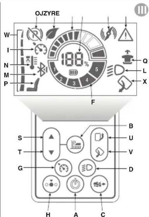
If all safety conditions are met, the white part of the circular element of the display lights up (fig.13III.F, 13III.Y, 13III.Z) and the battery status is displayed (13.F and 13.Y), the cutting height (13.W) and the active functions. The machine is ready to be used (see chap. 7.4).

Press the button fig. 13.B to engage/disengage the cutting means.
- When the cutting means are engaged, they become operational after a few seconds.
- When the cutting means are disengaged, a brake is applied simultaneously to stop them rotating after a few seconds.
NOTE
If the cutting means are engaged without taking the necessary safety precautions, the machine shuts down and cannot be restarted (see par. 7.2.2)

Holding down the button fig. 13.C gives consent for reverse mowing.
For reverse cutting, engage the cutting means and simultaneously hold down the button.
NOTE
A single buzzer signal indicates the lack of consent for reverse cutting.

Pushing the button fig. 13.D turns the beacon on/off.
When the beacons are ON, icon fig. 13.L is illuminated

Pressing the button in fig. 13.G activates/deactivates the "CRUISE CONTROL" function. The Cruise Control command is used to maintain the desired speed in forward gear without having to keep the drive pedal pressed.
- By pressing the “CRUISE CONTROL” button (Fig. 13.G) while moving forwards, the machine will maintain the speed reached at that moment, without the driver having to act on the drive pedal (Fig. 12.F). When the function is active, the icon in fig. 13.I. is illuminated
NOTE
The "CRUISE CONTROL" function cannot be activated in reverse gear.
NOTE
Speeds may vary with respect to the selected values when the machine is moving up or down slopes.
To disengage the device and reset speed control using the drive pedal (fig. 12.F) simply:
- press the button fig. 13.G. or
- press the drive pedal (fig. 12.F).

This button (fig. 13.H) is used to select 3 different cutting means rotation speeds.
- ECO: The cutting means rotation speed is reduced to extend the battery life. When this function is selected, the "leaf" icon is illuminated (fig. 13.J).
ATTENTION
It is not recommended to use this function in heavy grass cutting conditions (cutting of dense, high, humid grass).
- NORMAL: standard cutting means rotation speed for use in normal mowing conditions
- BOOST: The rotation speed of the cutting means is increased to cut grass in more difficult conditions (dense, tall, wet grass). When this function is selected, the "rotary blade" icon is illuminated (fig. 13.R). Battery life is reduced.
These buttons are used to raise (fig. 13.S) and lower (fig. 13.T) the cutting means assembly, which may be positioned at 7 different cutting heights. See paragraph 6.4.2.

With these buttons it is possible to open (fig. 13.U) and close (fig.13.V) the grass catcher. See paragraph 7.5.4.

Attention icon
If icon fig. 13.E is illuminated, it this indicates failure to comply with safety conditions or a possible malfunction of the machine (see chap. 15).

Battery LED
The LEDs fig. 13.F generally indicate the charge level of the machine's batteries but in particular combinations their lighting status provides information about machine malfunctions (see chap. 15).

"Bluetooth" icon
The icon in fig. 13.M is illuminated when the machine and the data exchange device are connected.

Controller and/or motor over-temperature icon
The icon in fig. 13.N indicates overheating of electrical components. See chap. 15.

Transmission engagement / disengagement lever icon
The icon in fig. 13.O is illuminated when the transmission is not engaged (see par. 6.3 and chap. 15).

Operator on-board icon
The icon in fig. 13.P is illuminated when operator leaves the driving seat (see par. 7.2.2).

The icon in fig. 13.Q is illuminated if the emergency button is activated (see par. 6.5).

ECO icon
The icon in fig. 13.J is illuminated when the ECO mowing mode is selected.

BOOST icon
The icon in fig. 13.J is illuminated when the BOOST mowing mode is selected.

Grass catcher symbol
The symbol fig. 13.X indicates that the grass catcher is raised and that it must be closed again before resuming work.

Cutting height symbol
The symbol fig. 13.W is graphically divided into seven sections, each of which indicates a different cutting height.

Digit percentage of battery charge
The digits fig. 13.Y indicate the percentage of battery charge.
NOTE
Should the machine show an anomaly, the digits provide a numeric error code identifying the anomaly.

ATTENTION
If necessary, provide the numerical error code to the Authorized Service Centre.

Current absorption indicator
The indicator fig. 13.Z. indicates the current absorption level of the battery by the machine.
NOTE
To increase battery life, adjust the cutting height and forward speed of the machine so that the absorption of the battery is kept in the green area of the indicator.
6.10 BLUETOOTH FUNCTION (IF AVAILABLE)
The Bluetooth function provides short-distance direct wireless connection between the machine and another device. The specific data exchange App must be installed on the device:
-
download the App using the QR Code shown in fig. 43.
-
follow the instructions.

The bluetooth connection is activated automatically when the machine is started and successful connection with the device is confirmed when the icon in fig. 13.M is illuminated.
Make sure that the connection with the device/App is active.
7. USING THE MACHINE
WARNING
The safety regulations to follow are described in chap. 2. Strictly comply with these instructions to avoid serious risks or hazards.
7.1 PRELIMINARY OPERATIONS
Before starting to mow, it is necessary to carry out several checks and operations to ensure you can work efficiently and in maximum safety.
7.1.1 Checking the battery
Charge the battery fully before using the machine for the first time after purchase (chap. 8.2.2).
Always check the battery state of charge before using the machine (Fig. 13.F).
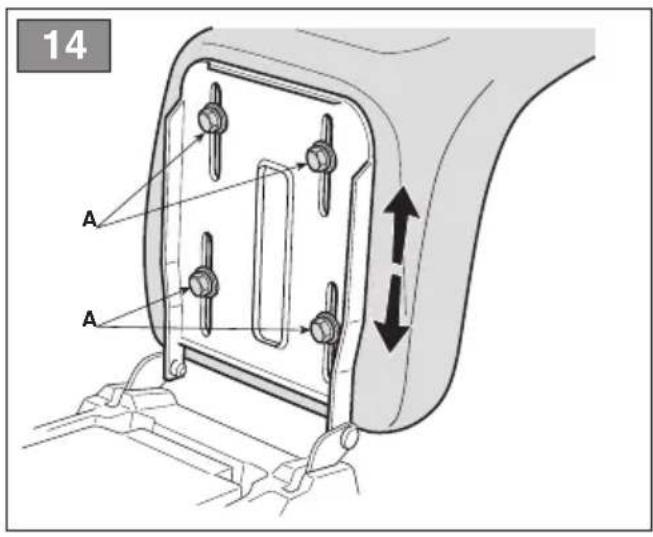
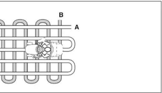
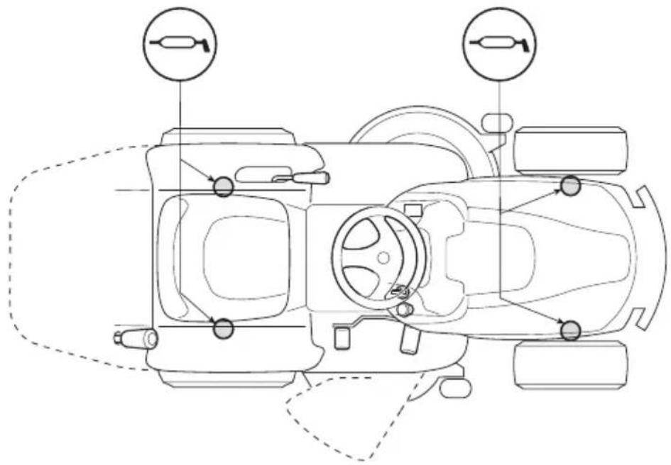
7.1.2 Seat adjustment
To change the position of the seat, loosen the four fixing screws (fig. 14.A) and slide the seat along the slots on the support. When the required position is found, fully tighten the four screws (fig. 14.A).
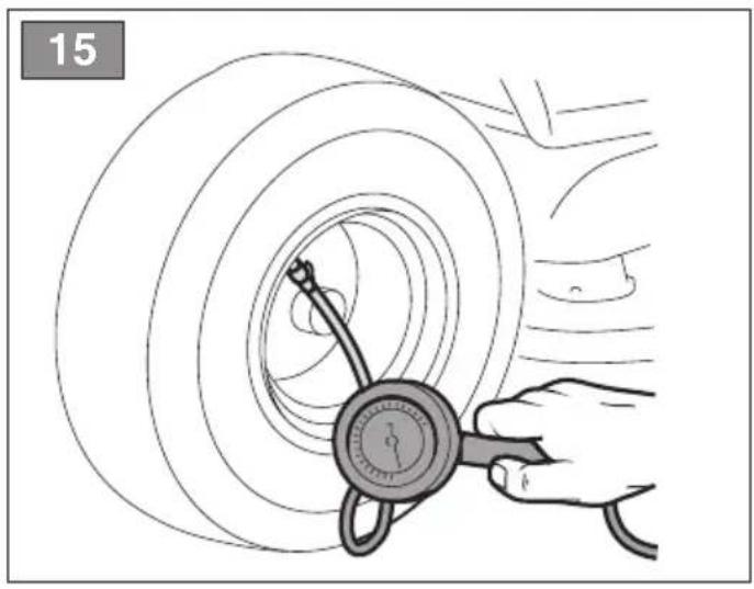
7.1.3 Tyre pressure
Having the right tyre pressure is the main condition for ensuring that the cutting means assembly is horizontal and mows evenly.
- Unscrew the protective caps
- Connect a compressed air line with a gauge to the valves (fig. 15)
- Adjust the pressure according to the values indicated in the "Technical Data" chart.
7.1.4 Preparing the machine before starting work
NOTE
This machine can be used to mow lawns in a number of different ways; before starting, prepare the machine based on how the lawn is to be mowed.
a. Prepare the machine for cutting and lateral grass discharge (for models with side discharge only):
Always make sure that the spring inside the deflector (Fig. 6.B) and the safety lever (Fig. 7.B, 8.B) operate correctly, holding it firmly in the lowered position.
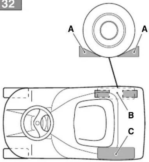
b. Pre-set for cutting and chopping grass in the grass catcher (only for models with rear grass catcher "I" and "II")
Hook the grass catcher (fig. 16.A) to the supports (fig. 16.B) and centre it with respect to the rear plate. Centring is ensured by using the right support as a lateral support.
Make sure that the lower pipe of the grass catcher opening is attached to the pawl (fig. 16.C).
c. Pre-set for cutting and chopping grass in the grass catcher (only for models with rear grass catcher "III")
See par. 5.8.
d. Pre-set for grass cutting and rear grass discharge on the ground (only for models with rear grass catcher)
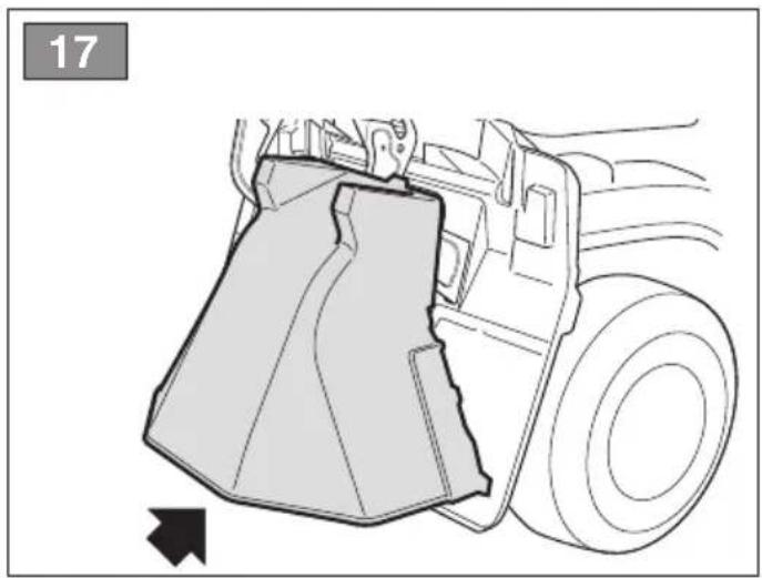
If you decide to work without the grass catcher, a rear discharge guard kit is available upon request (fig. 17; par 16.5) which must be securely mounted on the rear plate as indicated in the instructions provided.
e. Pre-set for cutting and chopping grass If you decide to mow grass, mulch it and leave it on the lawn, a "mulching" kit is available upon request (chap. 16.1). This has to be attached to the rear plate as indicated in the instructions.
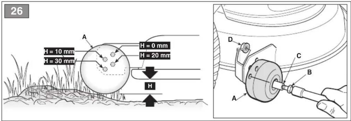
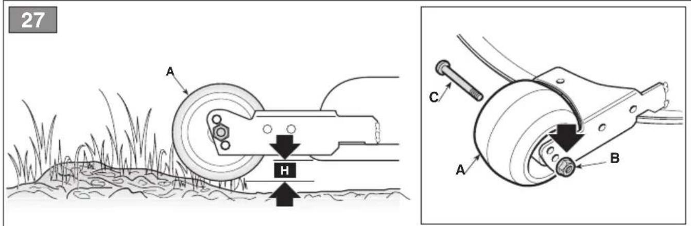
7.1.5 Positioning the anti-scalping wheels
The anti-scalping wheels are used to reduce the risk of tearing up sections of lawn, which can occur when the edge of the cutting means assembly drags over irregular ground. Position the wheels as indicated (par. 8.3).
7.2 SAFETY CHECKS
Run the following safety checks and ensure that the results correspond to those outlined in the tables.

SAFETY INSTRUCTION
Always perform safety checks before use.
7.2.1 General safety check
| Object Result | |
| Battery No damage to | casing and cover. |
| Rear discharge protection, grass catcher (only for models with rear grass catcher) | Good condition. No damage. Properly installed. |
| Side discharge protection (for models with side discharge only) | Good condition. No damage. Properly installed. |
| Electrical cables All insulation intact. | No mechanical damage. |
| Object Result | |
| Operate the machine forwards/reverse and release the drive pedal. | The machine slows down and stops. |
| Safety devices Proceed as indicated in par. 7.2.2 |
7.2.2 Control of safety devices
The safety devices work in two ways:
A. they prevent the electric engine from starting if all the safety requirements have not been met;
B. by stopping the electric engine if even just one of the safety requirements is lacking.
| Status Action Result | | |
| Operator seated.Drive pedal in neutral position(pedal released).Emergency button deactivated. | Fully insert the key The machine is ready to be turned ON. |
| Machine on or in operation. | The operator stands up from the seat. | All services are deactivated. The icon in fig. 13.E icon flashes and the icon in fig. 13.P is illuminated. |
| Operator seated.Drive pedal in forward or reverse position. | Try to start the machine. The icons in fig. 13.E and fig. 13.O remain ON, battery LEDs 1, 2, 4 and 5 flash.Pushbutton panel of type “I” e “II”Pushbutton panel of type “III” |
| Emergency button activated. Attempt to start the machine. The machine switches ON. The icon in fig. 7.E flashes and the icon in fig. 7.O is illuminated. Drive and cutting means do not work. |
| Cutting means engaged. Reverse is activated without holding down the reverse mowing consent button. | The cutting means disengage. |
| Cutting means engaged. Lift the grass catcher or remove the rear discharge guard (for rear collection models only) | The cutting means disengage. |
| Machine ON and Operating. Release the drive pedal. The machine slows down and stops. |
| Machine ON and Operating. Test drive. | No unusual vibrations, no unusual | sound, correct operation of the steering, controls and pedals. |
DANGER
If any results do not to match the indications in the tables, do not use the machine! Contact an Authorised Service Centre to have it checked and repaired if necessary.
NOTE
Always bear in mind that the safety devices prevent the electric engine from starting if safety requirements have not been met. In such cases, once start-up consent has been reset, remove the key before starting the machine again.
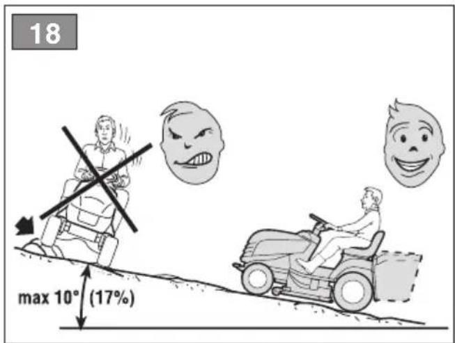
7.3 USING ON SLOPES
Comply with the limits indicated in the "Technical Data" Tables as in "fig. 18" regardless of the mowing direction.
Remember there is no such thing as a "safe" slope. Driving on grass slopes requires particular care. To prevent overturning or loss of control over the machine:
- Never mow across the face of the slope. Lawns on slopes must be mowed by moving up and down and never across them in forward gear. When changing direction, take great care that the wheels facing the slope do not hit any obstacles (such as stones, branches, roots, etc.) that may cause the machine to slide sideways, tip over or make you lose control.
- Do not stop or start suddenly when going up or downhill;
- Shift to drive gear very gently paying particular attention to prevent the machine from tipping up.
- Reduce speed:
• before changing direction and during tight turns
- before tackling a slope, especially downhill, to ensure a safe braking distance.
- Never switch to reverse gear to decrease speed when going downhill: this could cause loss of control of the machine, especially on slippery ground.
7.4 START-UP
To start the machine:
- Check that the transmission is engaged (par. 6.3).
- Sit in the operator's position.
- Fully insert the key (fig. 12.A).
a. For models type "I" and "II":
- Wait for the machine's electrical check to be performed, during which the icons on the pushbutton panel will flash.
- Press the power button (Fig. 13.A).
- Wait until the "Ready" icon (fig. 13.K) is ON steady.
b. For models type "III":
- Wait for the electrical check of the machine to be performed, during which the icons present within the central circular area of the pushbutton panel light up (fig. 13III.F, 13III.Y, 13III.Z).
- Press the power button (Fig. 13.A).
- Wait until the battery status icons (13.F and 13.Y), the cutting height (13.W) and the other active functions are illuminated.
NOTE
At the end of the electrical check, the headlights light up for a moment.
7.5 OPERATION
7.5.1 Drive and transfers
When moving the machine:
- disengage the cutting means (fig. 13.B);
- bring the cutting means assembly to the highest position;
- Press the drive pedal to move the machine in the required direction of driving and set the required speed by adjusting the pressure on the pedal.
- Go to the work area.

DANGER
Drive must be engaged in accordance with the modes described (paragraph 6.2) to avoid sudden meshing, jerking start and loss of control of the vehicle, especially on slopes.
NOTE
Reverse must only be engaged when the machine has stopped.
7.5.2 Grass cutting
- Set the cutting means assembly to the work position (par. 6.4).
- Engage the cutting means (fig.13.B) only on grass lawns; do not engage them on stony ground or when the grass is very high.
- When starting to cut grass, start off slowly and carefully.
- Adjust speed and cutting height (para 6.4) in relation to lawn conditions (grass height, density and humidity) and the amount of grass to be cut.

NOTICE
The forward work speed decreases if the battery charge threshold falls below 40% (par. 8.2.2).
NOTE
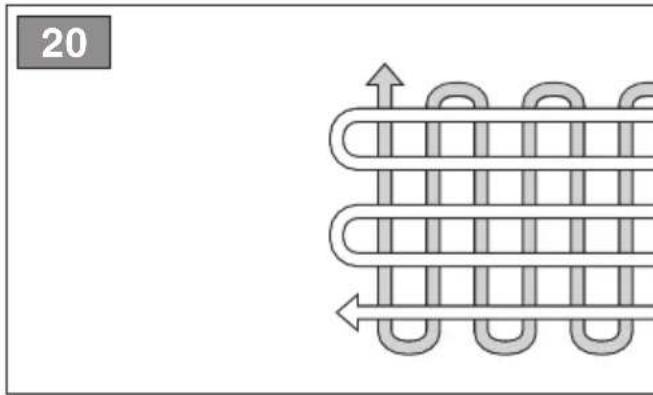
The appearance of the lawn will be improved if the grass is always cut at the same height and in two alternating directions (fig. 20).
NOTE
To proceed in reverse gear with the cutting means engaged, press and hold the consent button (fig 13.C) so that the motor does not stop.
Disengage the cutting means and move the cutting means assembly to the highest position:
- When moving between work areas
- When driving on grass free surfaces
- Every time it is necessary to overcome an obstacle.
7.5.3 Suggestions for maintaining a nice lawn
- To keep a lawn green and soft with a good appearance, it should be cut regularly. A lawn can be composed of different types of grass. If the lawn is cut frequently, grass and roots grow more vigorously, forming a solid grassy bed; if the lawn is cut is less frequently, higher grass and weeds start growing (clover and daisies, etc.).
- It is always better to cut the grass when dry.
- The cutting means must be in good condition and well sharpened so that the grass is cut straight without a ragged edge that leads to yellowing at the ends.
- The frequency of mowing should be in relation to the rate of growth of the grass, which should not be left to grow too much between one cut and the next.
- During hot and dry periods, the grass should be cut a little higher to prevent the ground from drying out.
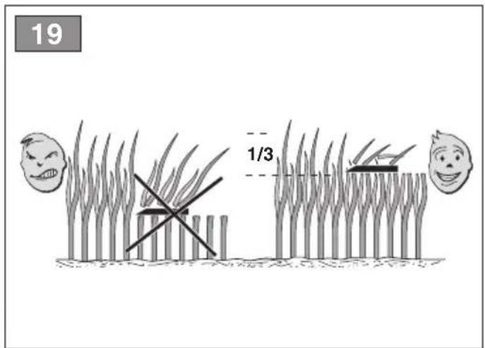
- The best height of the grass on a well-kept lawn is approx. 4-5 cm and with one mowing, you do not need to remove more than one third of the total height. If the grass is very tall, it should be cut twice in a twenty-four hour period; The first time with the cutting means at maximum cutting height and if necessary with open trail and the second cut at the height desired.
- The lawn will have a better appearance if the cuts are made by alternating them in both directions (fig. 20).
- If the discharge chute tends to get blocked with grass, you should reduce the forward speed as it may be too high for the condition of the grass. If the problem persists, the probable causes are either badly sharpened cutting means or deformed fins.
- Be very careful when mowing near bushes or kerbs as these could distort the horizontal position of the cutting means assembly and damage its edge as well as the cutting means.
7.5.4 Emptying of the grass catcher (for rear collection models only)
NOTE
The grass catcher can only be emptied with the cutting means disengaged, otherwise the engine stops.
NOTE
Do not let the grass catcher become too full as this may block the discharge chute.
A continuous buzzer indicates when the grass catcher is full: Proceed as follows:
- Disengage the cutting means (par.13.B) and the audible signal will stop;
- Stop the machine.
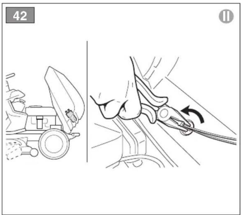
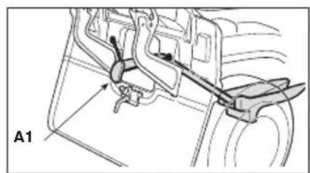
a. For models type "I" and "II":
- Extract the lever (fig. 21.A - if available) or grasp the rear handle (fig. 21.A1) and overturn the grass catcher to empty it.
- Move the machine about 1 m.
- Close the grass catcher again so that it remains coupled to the pawl (fig. 21.B).
b. For models type "III":
- Press the grass catcher opening button (fig. 13.U) for about 1 s to open it completely and empty it; alternatively, the grass catcher opening button can be held down until the opening required for emptying is reached. When the button is released, the bag will remain in the position reached.
- Move the machine about 1 m.
- Press and hold the grass catcher closing button (fig. 13.V) to close it completely.
NOTE
If the key is fully inserted (fig.12.A), pressing the reverse button (fig.13.C) together with the opening (fig.13U) or closing (fig.13V) buttons is possible open or close the grass catcher even when the driver is not sitting on board.
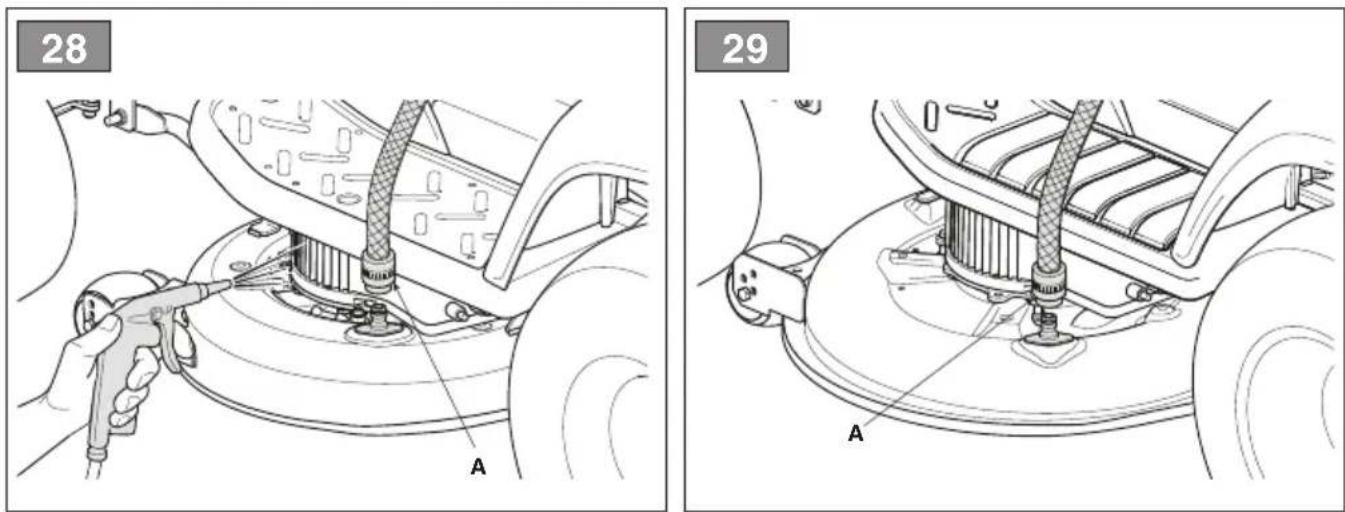
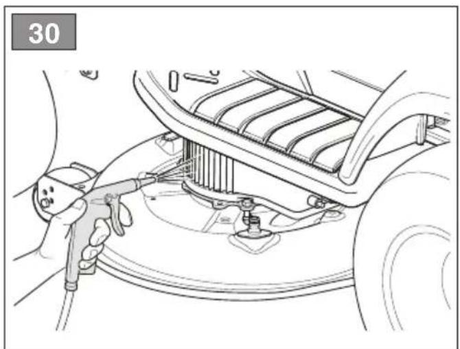
7.5.5 Cleaning the discharge chute (for rear collection models only)
Cutting very tall or wet grass, particularly at excessively high speed, can clog up the discharge chute. If it clogs, follow the instructions provided in par. 8.4.2.
7.5.6 Mowing completed
When mowing has been completed:
- disengage the cutting means;
- turn around with the cutting means assembly in its highest position. (par. 6.4)
7.6 STOP
To stop the machine:
-
Release the drive pedal to stop the drive gear.
-
Turn off the machine by removing the key.
NOTE
To save battery power, do not leave the key in the "run" position when the machine is not in use.
7.7 AFTER USE
- Allow the machine to cool before storing it in an enclosed space.
- Clean (par. 8.4).
- Make sure there are no loose or damaged components. If necessary, replace the damaged components and tighten any screws and loose bolts or contact the authorised service centre.
- Position the machine near to a power socket and charge the battery * (par. 8.2.2) so that it is ready to be used when next required.
whenever the machine is left unattended, the operator leaves the driving seat or parks the machine:
- Stop the machine;
- bring the cutting means assembly to the lowest height position (1)
- make sure that all moving parts have come to a complete stop;
- remove the ignition key;
ATTENTION
Always leave the machine in a shaded area or sheltered environment at a temperature below +35 °C
8. ROUTINE MAINTENANCE
DANGER
The safety regulations to follow are described in chap. 2. Strictly comply with these instructions to avoid serious risks or hazards.
Before commencing any inspections, cleaning or maintenance/adjustments on the machine:
- disengage the cutting means;
-
stop the machine;
-
make sure that all moving parts have come to a complete stop;
- Remove the key from the ignition;

DANGER
Never leave the key inserted or within reach of children or inappropriate people.
- read the relevant instructions;
- use suitable clothing, protective gloves and goggles
The frequency and type of procedures are outlined in the "Maintenance table". The table will help you maintain your machine's safety and performance. It summarises the main interventions to be made and the frequency applicable to each of them. Carry out the relevant task as soon as it is scheduled to be performed. The use of non-genuine and/or incorrectly assembled spare parts and attachments could adversely affect machine operation and safety. The manufacturer shall decline all liability in the event of injuries or damages caused by such parts. Genuine spare parts are supplied by Authorised Assistance Centres and Dealers.
8.2 BATTERY
8.2.1 Battery power reserve
Battery life (and therefore the area of lawn that can be mowed before recharging) is essentially affected by:
A. Work factors involving higher energy requirement (e.g. cutting with dense, tall, humid grass).
B. Operator behaviour that should be avoided:
- switching the machine on and off frequently whilst working;
- Setting a cutting height that is too low for the lawn conditions;
- Working at a speed that is too high for the amount of grass to be removed.
C. Environmental factors, such as a high ambient temperature, above +35 °C.
To optimize the life of the batteries, it is always advisable to:
8.2.2 Recharge the battery
The energy required for operating the machine is provided by a battery which requires careful maintenance to ensure efficiency and a long service life.
The machine battery must always be charged:
- Before using the machine for the first time after purchase;
- When the minimum state of charge is reached (Fig. 13 F).
- Before any prolonged period when the machine is not in use
- At least once a month during storage.
- before starting up the machine after a prolonged period of inactivity.
ATTENTION
When the battery is not connected to the mains network with the specific battery charger, battery charge will be lost even if the battery is not used. If the battery is subject to a deep discharge, it could be seriously damaged to the point that it can no longer be used. The warranty does not cover damage caused by a battery not having charged correctly.
ATTENTION
Charging must take place exclusively via the battery charger (fig. 23.A). Other recharging systems can irreversibly damage the battery.
ATTENTION
The batteries must only be charged in an area protected against poor weather conditions, in the shade, at a recommended temperature of between +5 e +35 °C.
NOTE
The battery can be charged at any time, even partially, with no risk of damaging it.
SAFETY INSTRUCTION
Do not carry out maintenance or cleaning operations while the battery is charging.
To charge the battery:
- bring the machine to an earthed power socket (to prevent the use of an extension cable) and remove the key;
- Lift the seat;
• Life the cap on the recharging socket (fig. 22.A);
- Connect the battery charger supplied to the recharging socket (fig. 23.A) with the specific bayonet mount for the respective connector (fig. 23.B);
- Connect the battery charger to the mains by inserting its plug (fig. 24).
To charge the battery, a socket with a differential safety switch (Fig. 25.A) is supplied (where required) to which the charge cable (Fig. 25 E) must be connected.
The socket with the differential safety switch must be connected to the mains power network and an operating test must be carried out:
- Press the "RESET" button (Fig. 25 BA) to activate operation. The indicator light must be "ON" (Fig. 25.C).
- Press the "TEST" button (Fig. 25.D) to perform the operating test. The indicator light must be "OFF" (Fig. 25.C).

DANGER
If the operating test is not completed successfully, the socket with the differential switch must not be used. If the operating test is completed successfully, it can be used and the operator can proceed with the charging stage.
The complete recharge takes about 2-8.5 hours (depending on the battery and the battery charger), during which the signalling LEDs (fig. 13.F) flash progressively. When each individual charge threshold is reached, the respective LED remains lit steadily, while the others continue to flash.
The battery can be kept in charge mode for an indefinite period of time.
| Charge status (SOC) | Led lighting (type “I” and “II”) | Led lighting (type “III”) |
| SOC > 80% |  |  |
| 60% ≤ SOC < 80% |  |  |
| Charge status (SOC) | Led lighting (type “I” and “II”) | Led lighting (type “III”) |
| 40% ≤ SOC < 60% |  |  |
| 20% ≤ SOC < 40% |  |  |
| 10% ≤ SOC < 20% |  |  |

ATTENTION
It is possible to stop charging the battery when the charge level is between LEDs 1 and 4. Do not interrupt the charging phase when LED 5 flashes but wait for it to light up steadily. When all the LEDs are lit steadily, the battery is 100% charged.

NOTICE
Battery charging times may increase if the machine has been used in heavy-duty work conditions with consequent indication of battery overheating (chap. 15).

NOTICE
If a battery becomes completely discharged, the signalling LEDs remain off until the minimum charge threshold is reached.
NOTE
When the charge level drops below the 10% threshold, the first battery LED begins flashing. The cutting means are disengaged and the battery must be re-entered and recharged.
When the charging operation has been completed, the charge system reduces the current supply as far as necessary to maintain and reintegrate the battery charge to optimal values.

NOTICE
If, when the battery charger is connected to the tractor, the 5 LEDs fig. 13.F all flash at the same time, it means charging is not in progress. Check the battery charger/mains connection.
NOTE
Energy consumption to maintain the battery charge is extremely low with negligible cost.
NOTE
While charging, all machine functions are disabled, even when the key is fully inserted.

ATTENTION
The battery installed on the machine has been designed and constructed for this type of use, therefore:
- DO NOT disconnect or remove the batteries from their respective housings;
- DO NOT replace the batteries with other non-original batteries;
- DO NOT carry out interventions unless they have been indicated in this manual.
In the event of any problems with the batteries, contact your Dealer.
8.3 ANTI-SCALPING WHEELS
Thanks to the various mounting positions of the wheels, it is possible to maintain a safety distance "H" between the edge of the cutting means assembly and the ground (fig. 26.A). fig. 27.A). Adjust the position of the anti-scalping wheels according to how irregular the ground is.

SAFETY INSTRUCTION
This operation must always be performed on both wheels, positioning them at the same height, with the machine off.
a. For models with side discharge
To change the position:
- unscrew and remove the screw (fig. 26.B);
- reposition the small wheel (fig. 26.A) with the spacer (fig. 26.C) in the hole corresponding to the desired distance;
- fully tighten the screw (fig. 26.B) in the nut (fig. 26.D).
b. For models with rear grass catcher:
To change the position:
- unscrew the nut (fig. 27.B) and remove the pin (fig. 27.C);
- Reposition the wheel (fig. 27.A) in the desired position
- reassemble the pin (fig. 27.C), making sure that the head of the pin (fig. 27.C) is facing the inside of the machine;
- fully tighten the nut (fig. 27.B).
8.4 CLEANING
Clean thoroughly following the instructions below every time it is used.
8.4.1 Cleaning the machine
- Clean the outside of the machine washing the plastic parts of the bodywork with a damp sponge using water and detergent, taking care not to wet the electric motors, the battery or the parts of the electrical system.
- To reduce fire hazards, keep the engine and the battery housing free of grass, leaves, or excessive grease.
- Lift the hood and clean with compressed air any dirt or grass residues that accumulate on top of the battery pack.
- Keep the pushbutton panel free of dirt and debris.

ATTENTION
Never use high pressure water or aggressive fluids to wash the bodywork and electric motors.
8.4.2 Cleaning the discharge chute (for rear collection models only)
If the discharge chute is clogged:
- remove the grass catcher or the rear discharge guard;
- remove the grass cuttings; you can reach them from the chute discharge opening.
8.4.3 Cleaning the grass catcher (only for rear grass catchers of type "I" and "II")
- Empty the grass catcher (par. 7.5.4).
- Shake it to remove grass cuttings and soil residue.
- Replace the grass catcher and clean the interior of the cutting means assembly (par. 8.4.4-a), now remove the grass catcher, empty and rinse it, then place it where it can dry quickly.
8.4.4 Cleaning the grass catcher (only for rear grass catchers of type "II")
- Empty the grass catcher (par. 7.5.4).
-
Remove the grass catcher (par. 5.8).
-
Shake it to remove grass cuttings and soil residue.
- Refit the grass catcher (par. 5.8).
- Close the grass catcher (par. 5.8) and wash the inside of the cutting means (par. 8.4.4-a).
- Remove the grass catcher (par. 5.8) and rinse it carefully.
8.4.5 Cleaning the cutting means assembly
Clean cutting means assembly thoroughly to remove any grass residue or debris.
WARNING
Keep people or animals away from the surrounding area when cleaning the cutting means assembly.
a. Cleaning the interiors
When washing the inside of the cutting means assembly and the discharge chute, the machine must be on firm ground with:
- the grass catcher or the rear discharge guard mounted in place (for rear collection models only)
- the side discharge chute mounted (for models with side discharge only);
- the operator seated;
- the cutting means assembly in the lowest position;
• the transmission in neutral;
• the cutting means engaged;
- Alternatively, connect a water tube to the dedicated coupling (fig. 28.A fig. 29.A), allowing water to flow through each cutting means for a few minutes, while they are in motion.
b. Cleaning the exterior
SAFETY INSTRUCTION
Do not allow debris and dried grass to accumulate in the upper part of the cutting means assembly in order to maintain maximum machine efficiency and safety levels.
To clean the upper part of the cutting means assembly:
- fully lower the cutting means assembly;
- blow with a jet of compressed air (fig. 30).
8.5 LUBRICATION
| Object Action |
| Steering wheel | Clean with compressed air. |
| Cutting means assembly | Lubricate the lifting points with oil (fig. 31). |
| Wheel axles Remove the wheels. Lubricate the axles with grease (Fig. 39.E). |
8.6 NUTS AND BOLTS
- Keep all nuts, bolts and screws tight to be sure the equipment is in safe working condition.
9. OCCASIONAL MAINTENANCE
9.1 SAFETY RECOMMENDATIONS
SAFETY INSTRUCTION
You must immediately contact your Authorised Service Centre or Dealer if the following malfunctions are found:
- the neutral position of the drive pedal (service brake)
- cutting means engage and disengage functions
- switching the drive to forward or reverse gears.
9.2 CUTTING MEANS ASSEMBLY / CUTTING MEANS
9.2.1 Aligning the cutting means assembly
The cutting means assembly should be properly adjusted to obtain an evenly mown lawn (fig. 19). If mowing is uneven, check the tyre pressure (par. 7.1.3).
If this is not sufficient to achieve an even cut, please contact your Dealer to adjust the alignment of the cutting means assembly.
9.2.2 Cutting means
Badly sharpened cutting means pull at the grass and cause the lawn to turn yellow.

SAFETY INSTRUCTION
Always replace damaged, bent or worn pairs of cutting means, together with their nuts and bolts, in order to maintain their balance.

WARNING
All work on the cutting means (disassembly, sharpening, balancing, repairing, reassembly and/or replacing) are demanding jobs that require special skills as well as special tools; For safety reasons, these jobs are best carried out at a Authorised Service Centre.

ATTENTION
Always use original cutting means bearing the code indicated in the "Technical Data".
NOTE
Given product evolution, the cutting means listed in the "Technical Data" table may be replaced in time with others having similar interchangeable and operating safety features.
9.3 REPLACING FRONT / REAR WHEELS
9.3.1 Preliminary operations

DANGER
Use a suitable lifting device.
Before changing the wheels it is necessary to complete some preliminary operations:
- Position the machine on a solid and even surface that guarantees stability of the machine.
- Stop the machine;
- Remove the key from the ignition;
- Position the lifting device in the lifting position near the wheel to be changed (par. 9.3.2; par. 9.3.3).
- Check that the lifting device is perfectly perpendicular to the ground.
9.3.2 Choice and positioning of the jack on the rear wheels
Position some wooden wedges (fig. 32.A) at the base of the wheel (fig. 32.B) next to the wheel to be changed (fig. 32.C).
For models with rear collection:
- The maximum possible jack height when closed is 110 mm. (fig. 33).
- Position the jack under the rear plate (fig. 34.A) at 180 ~mm from the side edge (fig. 33).
For side discharge models:
- The maximum possible jack height when closed is 110 mm. (fig. 35).
- Position the jack under the rear axle, in the point indicated in the diagram (fig. 36.A).
NOTE
In this position the jack allows you to raise only the wheel to be changed.
9.3.3 Choice and positioning of the jack on the front wheels
- Position some wooden wedges (fig. 37.A) at the base of the wheel (fig. 37.B) behind the wheel to be changed (fig. 37.C).
- The maximum possible jack height when closed is 110 mm.
- Place on top of the jack (fig. 38.A) a squared piece of wood (fig. 38.B) having a cross-section of about 10 x 10 cm.

ATTENTION
The thickness of the wood prevents damage to the front axle.
- During this stage, keep the wooden pad balanced on the jack with one hand. Lift the jack making sure that the wooden pad rests against the frame and the structural parts (fig. 38.C).
NOTE
The jack positioned in this way makes it possible to lift the entire front axle.
9.3.4 Changing the wheel

SAFETY INSTRUCTION
Make sure that the machine remains still and stable during the lifting process. If you notice anything out of the ordinary, lower the jack immediately, check and resolve any problems and lift the machine again.
- Remove the cover (fig. 39.A).
- Raise it enough to extract the wheel easily.
- Use a screwdriver to remove the snap ring (fig. 39.B) and the shoulder washer (fig. 39.C).
- Remove the wheel to be changed.
- Smear the axle (fig. 39.D) with grease.
- Mount the spare wheel.
- Carefully replace the shoulder washer and snap ring.
NOTE
Check that the two rear wheels are the same height (fig. 40.A) and that the difference between the external diameters of the two wheels (fig. 40.B) is no greater than 8-10 mm. On the contrary, to avoid uneven mowing, the cutting means assembly must be aligned by an Authorised Service Centre.
9.3.5 Repairing or changing tyres
The tyres are “Tubeless” and so all punctures must be repaired by a tyre repairer following the procedures required for this type of tyre.
9.4 REPLACING LED LAMPS
9.4.1 LED TYPE I
Loosen the lock nut (fig. 41.A) and remove the connector (fig. 41.B). Remove the LED illuminator (fig. 41.C), secured by screws (fig. 41.D).
9.4.2 LED TYPE II (bayonet type)
The bulbs have a bayonet fitting and are installed in the bulb holder, which can be taken out by turning it anti-clockwise with pliers (fig. 42).
10. STORAGE
When you intend to put your machine away for more than 30 days:
- Remove the ignition key.
- Clean the machine thoroughly.
-
Check the machine for any damage. If necessary, contact the authorised service centre.
-
Store the machine:
• with the cutting means assembly lowered
- in a dry place;
- protected against poor weather conditions, at a recommended temperature of between 0 and +40 °C.
• covered with a sheet if possible;
• in a place out of children's reach;
- making sure that keys or tools used for maintenance are removed.

ATTENTION
Make sure that the battery is fully charged at least once a month and always before use.
When re-starting the machine, set it up as indicated in chapter "7. "Using the machine".
11. HANDLING AND TRANSPORT

SAFETY INSTRUCTION
If you feel unable to carry out handling or transport in safe conditions, contact the Service Centre.
12. ASSISTANCE AND REPAIRS
This manual provides all the necessary information to run the machine and for correct basic maintenance operations which can be performed by the user. Any regulations and maintenance operations not described herein must be carried out by your Dealer or Authorised Service Centre, which have the necessary knowledge and equipment to ensure that the work is carried out correctly, maintaining the correct degree of safety and the original operating conditions of the machine. Any operations performed in unauthorised centres or by unqualified persons will totally invalidate the warranty and all obligations and responsibilities of the manufacturer.
- Only Authorised Service Centres can carry out guaranteed repairs and maintenance.
- The Authorised Service Centres only use genuine spare parts. Genuine spare parts and attachments have been designed specifically for machines.
- Non-original parts and attachments are not approved; use of non-original spare parts and attachments will jeopardise the safety of the machine and relieve the Manufacturer from all obligations or liabilities.
- It is advisable to send your machine once a year to an Authorised Service Centre for servicing, assistance and safety device inspection.
13. WARRANTY COVERAGE
The warranty conditions are intended for consumers only, i.e. non-professional operators. The warranty covers all material quality and manufacturing defects recognised during the warranty period by your Dealer
or Authorised Service Centre. The warranty is restricted to the repair or replacement of components recognised as faulty.
The warranty only applies to machines subjected to regular maintenance.
The user must follow all the instructions provided in the accompanying documentation.
The warranty does not cover damages resulting from:
- Failure to become familiar with the documentation accompanying the machine (Instruction manual).
• Professional use.
- Carelessness, negligence.
- External causes (lightning, impact, presence of foreign bodies inside the machine) or incidents.
- Incorrect use or assembly or prohibited by the manufacturer.
- Poor maintenance.
- Modification to the machine.
- Use of non-genuine spare parts (adaptable parts).
- Use of attachments not supplied or not approved by the manufacturer.
The warranty does not cover:
- The routine/occasional maintenance operations (described in the owner's manual).
- Normal wear and tear of consumables such as cutting means, wheels, beacons, safety bolts and wiring.
• Normal wear and tear.
• Deterioration in the appearance of the machine due to use.
• Cutting means supports.
- Any accessory expenses related to the enforcement of the warranty, such as costs incurred to travel to the user's location, transfer of the machine to the Dealer, rental of replacement equipment or calling of independent enterprises to perform maintenance work.
The user is protected by his or her own national legislation. The purchaser's rights under the national laws or his or her own country are not in any way restricted by this warranty.
14. MAINTENANCE TABLE
Use the boxes at the side to note the date or number of operating hours when the intervention was performed.
| Intervention Frequency | (hours) | Performed (Date or Time) Notes | |
| Check all fasteners | Before each use | | | | | | |
| Tyre pressure check | Before each use para. 7.1.3 | | | | | | |
| Safety checks/check controls | Before each use par. 7.2 | | | | | | |
| Check the drive release lever | Before each use para. 6.3 | | | | | | |
| Assembly / Check of the protections at the exit | Before each use para. 5.5 | | | | | | |
| Charging the battery | Before each use After each use Before storage | | | | | | par. 8.2 |
| General cleaning and inspection | After each use para. 8.4 | | | | | | |
| Checking for any damage to the machine. If necessary, contact the authorised service centre. | After each use | | | | | | |
| Cutting means positioning and sharpening check | 25 | | | | | | * |
| Replacing cutting means | 100 * | | | | | | |
| General lubrication | 25 par. 8.5 ** | | | | | | |
* This operation must be carried out by your Dealer or an Authorised Service Centre.
** General lubrication of all joints should also be carried out whenever the machine is to be left unused for a long period
15. TROUBLESHOOTING
| PROBLEM Cause Remedy | |
| 1. The machine will not switch on. | Low battery. Charge the battery (par. 8.2.2). |
| 2. Irregular cutting | Cutting means sharpening is reduced. | Contact an Authorised Service Centre Authorized. |
| High forward speed in relation to the height of the grass to be cut.Cutting means assembly full of grass. | Reduce forward speed and/or Increase the cutting height:Wait for the grass to dry.Clean the cutting means assembly. |
| 3. Unusual vibrations during use. | Cutting means incorrectly balanced.Cutting means loose.Loose parts.Possible damage | Contact an Authorised Service Centre authorized for verification, replacements or repairs. |
4. The icon in fig. 13.E remains ON and battery LEDs 2 and 5 flash.Pushbutton panel type “I” and “II” Pushbutton panel of type “III” Pushbutton panel of type “III” | Battery current overload caused by: | |
| 1. Work conditions too demanding. | Reduce forward speed: |
| Increase the cutting height: |
| 2. Slope too steep . | Reduce the forward speed and check the slope of the ground where you are working. |
5. The icon in fig. 13.N flashes. All the other indications in the push-button panel (icons/LEDs) remain functional and visible. | Pre-alarm for battery, drive motor and/or cutting means motor over-temperature because of: | |
| 1. Work conditions too demanding. | Reduce forward speed: |
| Increase the cutting height: |
6. The icons in fig. 13.E and fig. 13.O remain ON, battery LEDs , 2, and 4 flash.Pushbutton panel type “I” and “II” Pushbutton panel of type “III” Pushbutton panel of type “III”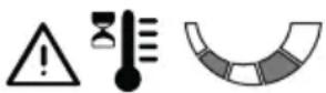 | Battery over/under temperature caused by: | Turn off the machine, wait for at least 5 minutes and then restart it. |
| 1. Work conditions too demanding. | Reduce forward speed: |
| Increase the cutting height: |
| 2. Unsuitable environmental conditions. | Work in an environment with a temperature appropriate for the machine's operating conditions. |
7. The icon in fig. 13.E remains ON and battery LEDs 1, 4 and 5 flash.Pushbutton panel type “I” and “II” Pushbutton panel of type “III” Pushbutton panel of type “III” | Current overload to cutting means caused by: | |
| 1. Work conditions too demanding. | Reduce forward speed: |
| Increase the cutting height: |
| 2. Obstructions that prevent rotation of the cutting means. | Remove the obstructions. |
| 3. The cutting means assembly is full of grass | Clean the cutting means assembly: |
8. The icons in fig. 13.E and fig. 13.O remain ON, battery LEDs 1 and 3 flash.Pushbutton panel type “I” and “II”  Pushbutton panel of type “III” Pushbutton panel of type “III”  | Cutting means motor over-temperature caused by: | Turn off the machine, wait for at least 5 minutes and then restart it. |
| Work conditions too demanding. | Reduce forward speed: |
| Increase the cutting height: |
9. The icon in fig. 13.E remains ON and battery LEDs 1, 3 and 5 flash.Pushbutton panel type “I” and “II” Pushbutton panel of type “III” Pushbutton panel of type “III” | Cutting means motor stall caused by: | |
| 1. Work conditions too demanding. | Reduce forward speed: |
| Increase the cutting height: |
| 2. Obstructions that prevent rotation of the cutting means. | Remove the obstructions. |
| 3. The cutting means assembly is full of grass | Clean the cutting means assembly: |
10. The icons in fig. 13.E and fig. 13.O remain ON, battery LEDs 1, 2 and 4 flash.Pushbutton panel type “I” and “II”  Pushbutton panel of type “III” Pushbutton panel of type “III”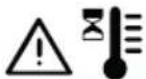  | Drive motor over-temperature caused by. | Switch off the machine and wait for at least 5 minutes before repeating the starting procedure. |
| 1. Drive motor under stress. | Reduce forward speed: |
| 2. Slope too steep . | Reduce speed and check the slope of the ground where you are working. |
| 3. Excessive mud on the wheels. | Make sure that the wheels are not blocked and clean as needed. |
11. The icons in fig. 13.E and fig. 13.O remain ON, battery LEDs 1, 2, 4 and 5 flash.Pushbutton panel of type “I” e “II”  Pushbutton panel of type “III” Pushbutton panel of type “III”  | The machine starts with the drive pedal not released (not in neutral position). | Switch off the machine and repeat the starting procedure only after having checked that the drive pedal is in the neutral position (pedal released). |
12. The icons in fig. 13.E and fig. 13.O remain ON, battery LEDs 1, 2, 3 and 5 flash.Pushbutton panel type “I” and “II” Pushbutton panel of type “III” Pushbutton panel of type “III” | Drive engagement/ disengagement lever in drive disengaged position. | Check the position of the drive engagement/ disengagement lever and, if necessary, return it to the drive engaged position. |
| If the problem persists, contact a Service Centre. |
| 13. The battery LEDs in fig. 13.F turn ON and OFF in sequence, from left to right, and vice versa. | Communication error between on-board electronic modules. | Switch off the machine and repeat the starting procedure |
| If the problem persists, contact a Service Centre. |
NOTE
For machines equipped with type "III" push-button panel, together with the LED error combination, a numeric error code is displayed in the battery charge percentage digits (fig. 13.Y). If necessary, provide the numerical error code to the Authorized Service Centre.
NOTE
For any further problems not listed in the table, immediately contact an Authorized Assistance Centre.
16. ATTACHMENTS
16.1 "MULCHING" KIT
It finely chops the grass cuttings and leaves them on the lawn (fig. 44.A1; fig 44.A2).
16.2 BATTERY CHARGER (FAST CHARGE)
This battery charger helps reduce battery recharging time. The list of type-approved battery chargers for this machine can be found in the "Technical Data" table.
This keeps the battery in good working order when the machine is in storage, guaranteeing an optimum level of charge and longer battery life (fig. 44.B).
16.3 TOWING KIT
To tow a small trailer (fig. 44.C).
16.4 CANVAS COVER
Protects the machine from dust when not in use (fig. 44.D)
16.5 REAR DISCHARGE GUARD KIT
Can be used in place of the grass catcher when mown grass is not collected (Fig. 44.A) (Only for models with rear grass catcher).
16.6 SNOW CHAINS 18"
Improved adherence of the rear wheels on the snow-covered sections and possibility of using snow ploughs (Fig. 44.F).
16.7 18" MUD / SNOW WHEELS
Improve drive performance on snow and mud (Figure 44.G).
16.8 TRAILER
To transport tools or tall objects within permitted load limits (Fig. 44.H).
16.9 SPRINKLER
To spread salt or fertilizers (Fig. 44.1).
16.10 LEAF AND GRASS COLLECTOR
To collect leaves and grass from grassy areas (Fig. 44.J).
16.11 SNOW BLADE
For clearing and accumulating removed snow at sides (Fig. 44.K).
ÍNDICE
| Estado de carga (SOC) | Encendido del led (tipo “I” y “II”) | Encendido del led (tipo “III”) |
| 60% ≤ SOC < 80% |  |  |
| 40% ≤ SOC < 60% |  |  |
| 20% ≤ SOC < 40% |  |  |
| 10% ≤ SOC < 20% |  |  |

ATENCIÓN
16.1 KIT PARA "MULCHING"
1.1 KUIDAS JUHENDIT LUGEDA
2. MASINA ÜLDISED OHUTUSHOIATUSED
2.1 ÜLDISED OHUTUSHOIATUSED
HOIATUS
8.3 PINNASESSE LÕIKAMIST TAKISTAVAD RATTAD
6.5 BOUTON D'ARRÊT D'URGENCE
11. MANUTENTION ET TRANSPORT
16.1 KIT DE MULCHING
- UPORABA STROJA....20
7.1 Pripremne radnje 20
7.2 Sigurnosne kontrole.... 20
7.3 Uporaba na terenima s nagibom ..... 22
7.4 Pokretanje 22
7.5 Rad....22
7.6 Zaustavljanje 24
7.7 Nakon korištenja....24
- REDOVNO ODRŽAVANJE....24
8.1 Općenito....24
8.2 Baterija 25
8.3 potporni kotačići 27
8.4 Čišćenje 27
8.5 Podmazivanje 28
8.6 Pričvrsne matice i vijci 28
- IZVANREDNO ODRŽAVANJE....28
9.1 Sigurnosne preporuke 28
9.2 Sustav noževa / noževi 28
9.3 Zamjena prednjih/stražnjih kotača..... 29
9.4 Zamjena LED žarulja 30
-
SKLADIŠTENJE....30
-
PREMJEŠTANJE I PRIJEVOZ ...... 30
- SERVISIRANJE I POPRAVCI 30
- ŠTO JAMSTVO POKRIVA 31
- TABLICA ODRŽAVANJA 32
- UTVRĐIVANJE PROBLEMA....32
- DODATNA OPREMA....36
16.1 Komplet za malčiranje 36
16.2 Punjač baterije (brzo punjenje) ...... 36
16.3 KOMPLET ZA VUČU 36
16.4 Zaštitna cerada.... 36
16.5 Komplet zaštite stražnjeg otvora za izbacivanje ....36
16.6 Lanci za snijeg 18"......36
16.7 Kotači za blato/snijeg 18" ....36
16.8 Prikolica.... 36
16.9 Rasipač 36
16.10 Sakupljač lišća i trave 36
16.11 Nož za čišćenje snijega 36
1. OPĆENITO
1.1 KAKO SE SLUŽITI PRIRUČNIKOM
Ikona "Ready" (Spreman)
Ikona sl. 13.K se pali kad je stroj upaljen i spreman za uporabu.

Ikona "Bluetooth"
Gumb "CRUISE CONTROL"
Ikona "Ready" (Spreman)
Ikona sl. 13.K se pali kad je stroj upaljen i spreman za uporabu.

Ikona "Bluetooth"
Gumb "CRUISE CONTROL"
7.3 UPORABA NA TERENIMA S NAGIBOM
Poštujte ograničenja koja se navode u tablici "Tehnički podaci" i na sl. 18, bez obzira na smjer kretanja.
Imajte na umu da ne postoji "sigurna" padina. Kretanje po terenima s nagibom zahtijeva posebnu pozornost. Kako biste izbjegli prevrtanja ili gubitak kontrole nad strojem:
- PLĀNOTĀ TEHNISKĀ APKOPE......24
8. PLĀNOTĀ TEHNISKĀ APKOPE
BRIESMAS
9.4 LED SPULDŽU MAINA
9.4.1 LED I TIPS
2. ALGEMENE VEILIGHEIDSWAARSCHUWINGEN
2.1 ALGEMENE VEILIGHEIDSWAARSCHUWINGEN
WAARSCHUWING
3.5 BESCHERMING VAN DE OMGEVING
6.7 AKOESTISCH SIGNAALAPPARAAT
| Status lading (SOC) | Inschakeling leds (type “I” en “II”) | Inschakeling leds (type “III”) |
| SOC > 80% |  |  |
| 60% ≤ SOC < 80% |  |  |
| 40% ≤ SOC < 60% |  |  |
| Status lading (SOC) | Inschakeling leds (type “I” en “II”) | Inschakeling leds (type “III”) |
| 20% ≤ SOC < 40% |  |  |
| 10% ≤ SOC < 20% |  |  |

LET OP
- BLI KJENT MED MASKINEN 7
- ORDINÆRT VEDLIKEHOLD....24
- EKSTRAORDINÆRT VEDLIKEHOLD.....28
3.4 VEDLIKEHOLD, LAGRING
4. BLI KJENT MED MASKINEN
4.1 BESKRIVELSE AV MASKINEN OG BEREGNET BRUK
Denne maskinen er en traktorklipper.
Maskinen har en elektrisk motor som driver klippeinnretningen, og en elektrisk motor som styrer trekkraften.
6.3 SPAK FOR INNKOBLING / UTKOBLING AV TRANSMISJONEN
6.9.1 Knappanel (type "I") fig. 13

Startknapp for maskin
Knapp for klipping i revers
Knapp for klipping i revers
Knapp for klipping i revers
7.1 INNLEDENDE OPPGAVER
8. ORDINÆRT VEDLIKEHOLD
8.1 GENERELT
FARE
9. EKSTRAORDINÆRT VEDLIKEHOLD
9.1 SIKKERHETSFORSKRIFTER

SIKKERHETSINSTRUKSJON
RYZYKO WYWRÓCENIA MA- SZYNY
natural_image
Two empty triangles side by side, no text or symbols present
| Estado de carga (SOC) | Iluminação do LED (tipo “I” e “II”) | Iluminação do LED (tipo “III”) |
| SOC > 80% |  | |
| 60% ≤ SOC < 80% |  | |
| 40% ≤ SOC < 60% |  | |
| 20% ≤ SOC < 40% |  | |
| 10% ≤ SOC < 20% |  | |

ATENÇÃO
16.1 KIT PARA "MULCHING"
Tritura bem fina a relva cortada e a deixa no relvado (fig. 44.A1; fig. 44.A2).
16.1 KIT PENTRU MULCI
3.5 OCHRANA ŽIVOTNÉHO PROSTREDIA
6.10 FUNKCIA BLUETOOTH (AK JE SÚČASTOU)
7.5 PRACOVNÁ ČINNOSŤ
7.5.1 Jazda a presuny
Počas presunu:
- UPORABA STROJA....20
7.1 Začetna opravila....20
7.2 Varnostni pregledi....20
7.3 Uporaba na nagnjenih terenih ..... 22
7.4 Zagon....22
7.5 Delo....22
7.6 Zaustavitev 24
7.7 Po uporabi 24
- REDNO VZDRŽEVANJE 24
8.1 Splošne informacije 24
8.2 Baterija 25
8.3 Kolesca za preprečevanje prenizke košnje....27
8.4 Čiščenje 27
8.5 Mazanje....28
8.6 Pritrdilne matice in vijaki 28
- IZREDNO VZDRŽEVANJE....28
INNEHÅLLSFÖRTECKNING
-
ALLMÄN INFORMATION ...... 2
-
ALLMÄNNA
SÄKERHETSFÖRESKRIFTER 2
-
SÄKERHETSFÖRESKRIFTER FÖR
ÄKGRÄSKLIPPAREN 5
WARNING FÖR KROSSNING
6.3 SPAK FÖR ATT KOPPLA IN/UR KRAFTÖVERFÖRINGEN