P5614 - Thermostat Emos - Free user manual and instructions
Find the device manual for free P5614 Emos in PDF.

| Product type | Wireless thermostat |
| Brand | Emos |
| Model | P5614 |
| Power supply (transmitter) | 2 x 1.5 V AAA alkaline batteries |
| Power supply (receiver) | 230 V AC / 50 Hz |
| Radio range | Up to 100 m in open field |
| Communication frequency | 868 MHz |
| Temperature measurement range | 0 °C to 40 °C |
| Measurement accuracy | ±1 °C at 20 °C |
| Temperature resolution | 0.1 °C |
| Temperature setting | 5 °C to 35 °C in 0.5 °C steps |
| Set temperature variation | 0.2 °C |
| Operating modes | Heating, cooling, frost protection (7 °C) |
| Temperature calibration | -3.0 °C to +3.0 °C in 0.5 °C steps |
| Max switched load | 230 V AC, 16 A (resistive), 4 A (inductive) |
| Clock accuracy | ±60 seconds per month |
| Dimensions (transmitter) | 28 × 120 × 77 mm |
| Dimensions (receiver) | 26 × 86 × 86 mm |
| Weight (transmitter) | 117 g |
| Weight (receiver) | 146 g |
| Operating temperature | 0 °C to 40 °C |
| Storage temperature | -20 °C to 60 °C |
| Safety | Disconnect power before installation; installation by qualified personnel |
| Maintenance and cleaning | Soft slightly damp cloth; do not immerse |
| Repairability | Refer to a specialist; do not repair yourself |
| Spare parts | Replaceable AAA batteries |
| General information | Compliant with Directive 2014/53/EU; declaration of conformity available at www.emos.eu |
Frequently Asked Questions - P5614 Emos
User questions about P5614 Emos
0 question about this device. Answer the ones you know or ask your own.
Ask a new question about this device
Download the instructions for your Thermostat in PDF format for free! Find your manual P5614 - Emos and take your electronic device back in hand. On this page are published all the documents necessary for the use of your device. P5614 by Emos.
USER MANUAL P5614 Emos
natural_image
Simple geometric diagram with a rectangle and a circle, labeled '1' at the bottom (no text or symbols within the shapes)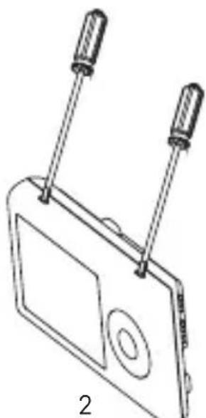
natural_image
Line drawing of a device with two screwdrivers and a screen, labeled '2' (no text or symbols on the diagram itself)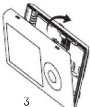
natural_image
Diagram of a device with an open lid and internal components, showing a rotating arrow (no text or symbols)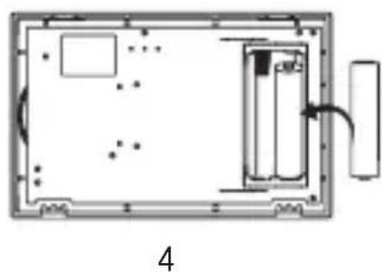
natural_image
Diagram of a device layout with labeled components and an arrow indicating direction (no text or symbols present)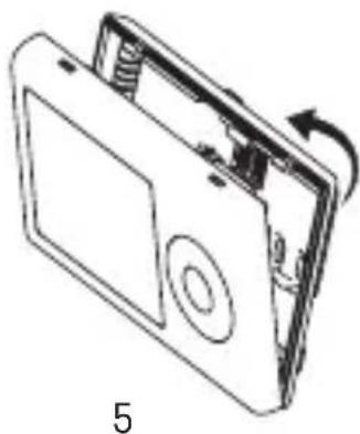
natural_image
Line drawing of a device with a scroll wheel and directional arrow indicating rotation (no text or symbols)5
6
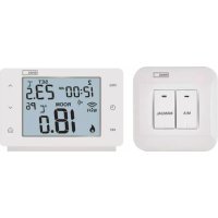
GB | Wireless Thermostat
The P5614 wireless thermostat is designed for controlling heating and air-conditioning systems.
Important
- Before the first use, make sure to carefully read the Operating Manual for the thermostat, as well as the manual for the boiler or air-conditioning equipment.
- Turn off power supply before installing the thermostat!
• Installation should be carried out by a qualified person! - During installation, follow applicable standards.
Technical specifications:
Switched load: max. 230 V AC; 16 A for resistive load;
4 A for inductive load
Clock accuracy: ±60 seconds/month
Temperature measurement: 0 °C to 40 °C with 0.1 °C resolution accuracy ±1 °C at 20 °C
Temperature setting: 5 °C to 35 °C in 0.5 °C increments
Temperature differential: 0.2 °C
Operating temperature: 0 °C to 40 °C
Storage temperature: -20 °C to 60 °C
Unit interconnection: via 868 MHz radio signal
Transmitter unit range: up to 100 m in an open area
Power supply:
Control unit (transmitter): 2× 1.5 V AAA batteries
Switching unit (receiver): 230 V AC/50 Hz
Dimensions and weight:
Control unit: 28 × 120 × 77 mm; 117 g
Switching unit: 26 × 86 × 86 mm; 146 g
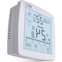
Display Description (See Fig. 1)
1 - operating mode
4 - set temperature
2 - cooling mode
5 - room temperature
3 – low battery indication
6 – heating mode
Control Button Description
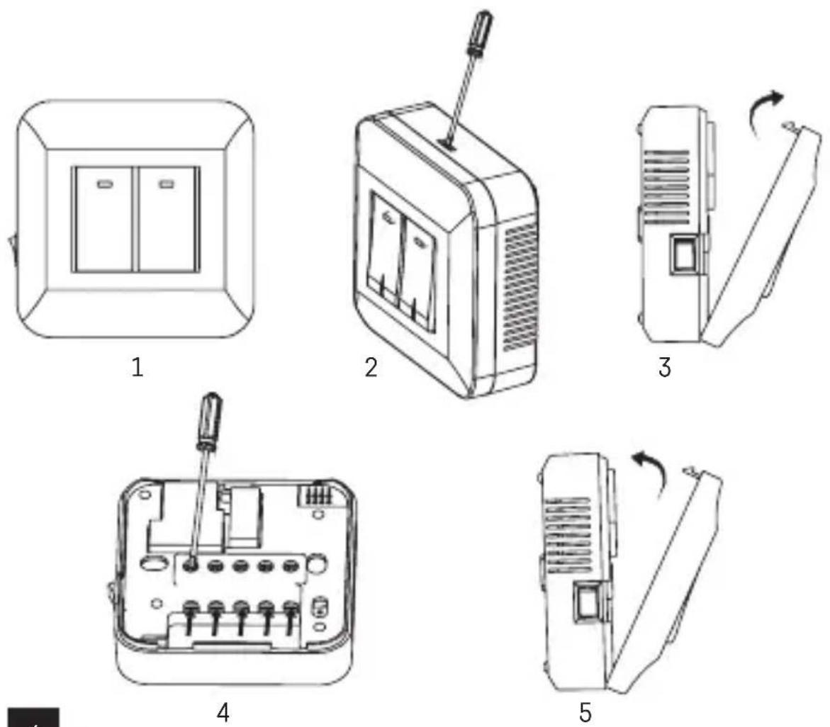
Thermostat (Transmitter Unit) (See Fig. 2)
1 - control/confirmation button
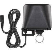
Receiver (Switching Unit) (See Fig. 3)
2 - main switch
3 - M/A button (red LED)
○ position – off
4 - MANUAL button (green LED)
| position – on
Rear of the Thermostat (See Fig. 4)
5 – LEARN button for pairing units
Procedure for Removing the Front of the Thermostat (See Fig. 5)
2, 3 – use a screwdriver to press down and hold the inner lock, remove the front cover.
Procedure for Removing the Front of the Switching Unit (See Fig. 6)
2, 3 – use a screwdriver to press down and hold the inner lock, remove the front cover.
INSTALLATION
Warning:
Before changing the thermostat, disconnect the heating/air-conditioning system from the main power in your flat. This will prevent potential injury by electric current.
Thermostat Installation
The rear of the thermostat carries 4 openings for mounting onto a wall. Use the enclosed screws and wall plugs to mount the thermostat.
Thermostat Placement
The placement of the thermostat (transmitter unit) significantly affects its functioning. Choose a location where members of the family spend most of their time, preferably on the inside wall where air circulates freely, with no direct sunlight. Do not place the thermostat in the vicinity of heat sources (such as TV sets, radiators, fridges), or close to a door. Failure to comply with these recommendations will prevent proper control over room temperature.
Switching Unit Wiring Diagram
Pump/Motorised Valve Connection Diagram
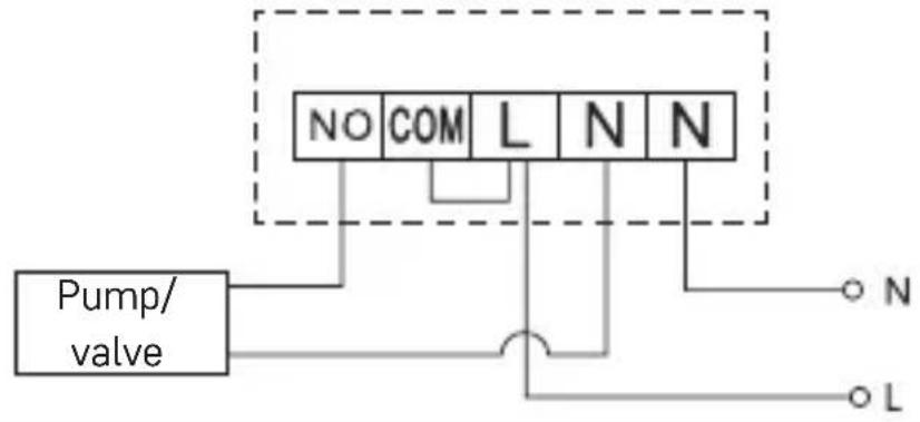
flowchart
graph TD
    A["Pump/ valve"] --> B["NO"]
    A --> C["COM"]
    A --> D["L"]
    A --> E["N"]
    A --> F["N"]
    B --> G["○ N"]
    C --> H["○ L"]
    D --> I["○ N"]
    E --> J["○ L"]
    F --> K["○ N"]
Floor Heating Connection Diagram
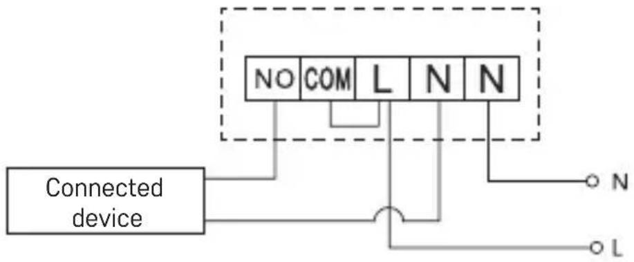
flowchart
graph TD
    A["Connected device"] --> B["NO"]
    A --> C["COM"]
    A --> D["L"]
    A --> E["N"]
    A --> F["N"]
    B --> G["Terminal N"]
    C --> H["Terminal L"]
    D --> I["Terminal N"]
    E --> J["Terminal N"]
    F --> K["Terminal L"]
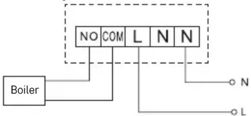
Boiler Connection Diagram
flowchart
graph TD
    Boiler["Boiler"] -->|NO| Grid1["Grid"]
    Boiler -->|COM| Grid2["Grid"]
    Boiler -->|L| Grid3["Grid"]
    Grid1 -->|N| Grid4["Grid"]
    Grid2 -->|N| Grid5["Grid"]
    Grid3 -->|N| Grid6["Grid"]
    Grid4 -->|N| Grid7["Grid"]
    Grid5 -->|N| Grid8["Grid"]
    Grid6 -->|N| Grid9["Grid"]
Pre-installed wire coupler will not be connected.
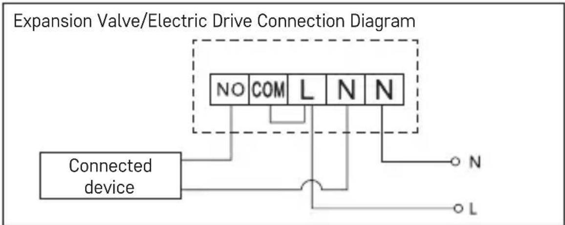
flowchart
graph TD
    A["Connected device"] --> B["NO"]
    A --> C["COM"]
    A --> D["L"]
    A --> E["N"]
    A --> F["N"]
    A --> G["L"]
    B --> H["Terminal block"]
    C --> H
    D --> H
    E --> H
    F --> H
    G --> H
Pairing the Control Unit with the Switching Unit
Both thermostat units must be paired before first use.
Pairing enables transfer of information between the control unit and the switching unit.
Setting is done via automated pairing (self-learning).
- Remove the cover of the thermostat (transmitter) and insert 2×1.5 V AAA batteries into the control unit (make sure polarity of the batteries is correct). Only use alkaline batteries. Do not use rechargeable batteries.
- Correctly connect the switching unit to voltage supply, turn the main switch to the I position and long press (for at least 10 seconds) the M/A button; a green diode will begin flashing.
- Long press (for at least 3 seconds) the LEARN button on the thermostat's (transmitter's) instrument panel.
The green diode on the switching unit will stop flashing and both units are now paired.
If you want to change the pairing code of the two units, repeat the entire pairing procedure from step 1 – the pairing code will be rewritten automatically.
If the thermostat is not working properly, please check the polarity of the batteries and whether they are sufficiently charged, or reset the thermostat by removing and reinserting the batteries.
Testing Wireless Communication between the Units
- Use the wheel to set a temperature a few degrees higher than the current room temperature.
- The red LED on the switching unit will light up.
- If the LED does not light up, move the control unit closer to the switching unit.
The maximum range between the control and switching unit is 100 m in an open space. The range may decrease in the interior as the signal is blocked by walls and other obstacles.
Main Switch
To turn on the switching unit, set the switch to the position.
If the heating/air-conditioning system is not used for an extended period of time, it is recommended to turn the switching unit off (switch the main switch to the position).
Choosing Operating Mode (Heating, Cooling, Anti-Freeze Temperature)
- Press and hold the control wheel for 5 seconds to enter mode settings.
- Turn the control wheel to select one of the following modes:
a. HEAT (heating system)
b. OFF (anti-freeze temperature of 7 °C)
c. COOL (cooling system)
- Press the control wheel to confirm your selection.
Room Temperature Calibration
Press and hold the control wheel for 5 seconds until the setting mode indicator starts flashing on the screen.
Press and hold the control wheel again for 5 seconds until the temperature calibration value starts flashing on the screen.
Use the wheel to set the temperature value of choice (-3.0 °C to 3.0 °C, in 0.5 °C steps) and confirm by pressing the wheel.
Room temperature calibration is used if, for example, the thermostat shows 21 °C but you want it to show 20 °C. In that case, the calibration value should be set to -1 °C.
LED Indicators
Automatic Mode
In automatic mode, a red LED will glow when the thermostat switches on the output relay.
Manual Mode
Press the MANUAL button; a green LED will light up.
To switch on the output relay, press the M/A button; a red LED will light up. To turn off manual mode, press the MANUAL button again; the green LED will switch off.
Display Backlighting
Pressing the control wheel activates display backlighting for 10 seconds.
Upkeep and Maintenance
The product is designed to serve reliably for many years if used properly. Here are some tips for proper operation:
- Read the manual carefully before using this product. - Do not expose the product to direct sunlight, extreme cold and humidity and sudden changes in temperature. This would reduce accuracy of detection.
- Do not place the product in locations prone to vibration and shocks – these may cause damage.
- Do not expose the product to excessive force, impacts, dust, high temperatures or humidity – these may cause malfunction, shorter battery life, damage to batteries and deformation of plastic parts.
- Do not expose the product to rain or high humidity, dropping or splashing water.
- Do not place any open flame sources on the product, e.g. a lit candle, etc.
- Do not place the product in places with inadequate air flow.
- Do not insert any objects in the product vents.
- Do not tamper with the internal electric circuits of the product – doing so may damage the product and will automatically void the warranty. The product should only be repaired by a qualified professional.
- To clean the product, use a slightly moistened soft cloth. Do not use solvents or cleaning agents – they could scratch the plastic parts and cause corrosion of the electric circuits.
- Do not immerse the product in water or other liquids.
- In the event of damage or defect of the product, do not perform any repairs by yourself. Have it repaired in the shop where you bought it.
- This device is not intended for use by persons (including children) whose physical, sensory or mental disability or whose lack of experience or knowledge prevents them from using it safely. Such persons should be instructed as to how to use the device and should be supervised by a person responsible for their safety. Children must always be supervised and must never play with the device.
Do not dispose of the product or the batteries after the end of their service life as unsorted municipal waste; use sorted waste collection points. Properly disposing of the product will help prevent negative effects on human health and the environment. Recycling of materials helps conserve natural resources. For more information about recycling this product, contact the municipal authority, organization for processing household waste or the point of sale where you purchased the product.
WARNING: The contents of this manual may be changed without prior notice – due to printing limitations, the symbols shown may differ slightly from those on the display – the content of this manual may not be reproduced without the manufacturer's permission.
Hereby, EMOS spol. s r.o. declares that the radio equipment type P5614 is in compliance with Directive 2014/53/EU. The full text of the EU declaration of conformity is available at the following internet address: http://www.emos.eu/download.
4-bouton MANUAL(LED vert)
position ⊢ allumé
Voyants LED (diodes)
Mode automatique
2 - interruptor principal