WS Regenerator - Water filter Kärcher - Free user manual and instructions
Find the device manual for free WS Regenerator Kärcher in PDF.

| Product type | Regeneration station for water softeners |
| Compatible models | Kärcher WS 50 and WS 100 |
| Operating principle | Ion exchange with brine regeneration (tablet salt) |
| Inlet water pressure (min/max) | 3 bar / 6 bar (without water hammer) |
| Inlet water temperature | 5 °C to 30 °C |
| Ambient operating temperature | 15 °C to 40 °C (do not expose to frost) |
| Raw water connection | 1 inch IG (mounting height 100–120 cm) |
| Wastewater connection | Recommended 1/2" hose, drainage via siphon or trough (max 2.5 m above) |
| Electrical connection | Standard mains socket (230 V / 50 Hz) |
| Salt consumption per regeneration | Approximately 5 kg of tablet salt (ref. Kärcher 6.287-016.0 – 25 kg) |
| Duration of an automatic regeneration | Approximately 2 hours |
| Regeneration program | Automatic (backwash, brine suction, filling and wash) or manual |
| Maintenance – Cleaning the salt tank | At least once a year |
| Maintenance – Cleaning the injector and strainer | Recommended during maintenance |
| Safety – Frost protection | Frost-free location mandatory |
| Safety – Use | For qualified persons only, wear protective goggles |
| Spare parts | Use only original Kärcher parts |
| Warranty | According to local distributor conditions |
| Intended use | Regeneration of WS 50/100 softeners with mains water or comparable quality |
| Suction fault – Common causes | Water pressure <3 bar, clogged injector, suction hose drawing air |
Frequently Asked Questions - WS Regenerator Kärcher
User questions about WS Regenerator Kärcher
0 question about this device. Answer the ones you know or ask your own.
Ask a new question about this device
Download the instructions for your Water filter in PDF format for free! Find your manual WS Regenerator - Kärcher and take your electronic device back in hand. On this page are published all the documents necessary for the use of your device. WS Regenerator by Kärcher.
USER MANUAL WS Regenerator Kärcher
natural_image
Technical line drawing of a mechanical assembly with no visible text or symbolsDE Deutsch 3
EN English 8
FR Français 13
IT Italiano 19
NL Nederlands 24
ES Español 29
PT Português 34
DA Dansk 39
NO Norsk 44
SV Svenska 49
FI Suomi 54
EL Ελληνικά 59
TR Türkçe 64
RU Русский 69
HU Magyar 75
CS Čeština 80
SL Slovenščina 85
PL Polski 90
RO Românește 95
SK Slovenčina 100
HR Hrvatski 105
SR Srpski 110
BG Български 115
ET Eesti 120
LV Latviešu 125
LT Lietuviškai 130
UK Українська 135
Register and win! www.kaercher.com/register-and-win
natural_image
Mechanical diagram showing a U-shaped pipe with two upward arrows indicating flow or movement (no text or symbols present)1 Steuerventil
Please read and comply with these original instructions prior to the initial operation of your appliance and store them for later use or subsequent owners.
Contents
Proper use .... EN .. 1 Requirements for operation EN .. 1
General information ..... EN .. 1 Terminology..... EN .. 1 Environmental protection EN .. 1 Warranty ..... EN .. 1 Spare parts..... EN .. 1 Symbols in the operating instructions..... EN .. 1
Safety instructions ..... EN .. 1 Application..... EN .. 1 Operations..... EN .. 1
Installation.... EN .. 2 Connections and installation EN .. 2 Programming unit control valve.... EN .. 2
Initial startup .... EN .. 2 Preparing WS regeneration station for operation ... EN .. 3
Regeneration .... EN .. 3 Regenerating WS 50 / WS 100 .... EN .. 3
Maintenance and care .... EN .. 3 General notes .... EN .. 3 Risk of frost .... EN .. 3 Maintenance Works ... EN .. 3 Appendix .... EN .. 4
Troubleshooting ..... EN .. 5
Proper use
- This station must exclusively be used for the regeneration of the softening plants WS 50 and WS 100. The plant is suitable for town water or water of similar quality. The plant works on the principle of ion exchanger process in neutral exchange. The regenerating agent is softening salt in form of a tablet (order no. 6.287-016.0 -25 kg) - The plant must not be used for the production of drinking water (possible damage to health!)
Requirements for operation
- The feed water (raw water) must be free of iron, manganese, heavy metals, oil as well as larger quantities of organic substances. Drinking water meets these requirements. - If the inlet pressure of the feed water (max. 6 bar) could be exceeded, a protective device against overpressure must be installed in the supply line to the water softening plant.
| Water temperature of the feed water (raw water) | min: 5 °Cmax: 30 °C |
| Ambient temperature Always during operation | >0°C min: 15°C max: 40°C |
| Inlet pressure of the feed water (raw water) | min: 3 bar max: 6 bar free of water impact |
General information
Terminology
Raw water
Untreated water, mostly drinking water, town water or well water.
Soft water
Water treated with the softening plant does not contain hardening minerals such as calcium and magnesium.
Injector
Water jet pump for sucking in the salt brine.
Exchanger
Also called filter container or filter tank. It contains the ion exchanger resin with which the water is softened.
lon exchanger resin
Filter material in the exchanger container that is used to soften the water.
Regeneration
The regeneration of the ion exchanger resin takes place by means of a multistage rinsing with a saline solution and water. This process is performed by means of the control valve.
Control valve
Multi-port-valve with an injector for performing the regeneration. The positions are travelled to by means of the programming unit.
Environmental protection

The packaging material can be recycled. Please do not place the packag-to the ordinary refuse for disposal, but ge for the proper recycling.

Old appliances contain valuable materials that can be recycled. Please arrange for the proper recycling of old licences. Please dispose your old applies using appropriate collection sys-
Notes about the ingredients (REACH)
You will find current information about the ingredients at:
www.kaercher.com/REACH
Warranty
The warranty terms published by the relevant sales company are applicable in each country. We will repair potential failures of your appliance within the warranty period free of charge, provided that such failure is caused by faulty material or defects in manufacturing. In the event of a warranty claim please contact your dealer or the nearest authorized Customer Service centre. Please submit the proof of purchase.
Spare parts
Use only original KÄRCHER spare parts. You will find a list of spare parts at the end of these operating instructions.
Symbols in the operating instructions
Danger
Warns about immediate danger which can lead to severe injuries or death.
⚠ Warning
Warns about possible danger which could lead to severe injuries or death.
Caution
Points out a possibly dangerous situation which can lead to light injuries or property damage.
Safety instructions
- Persons that are concerned with the installation, maintenance and operation of the plant must be correspondingly qualified and know and comply with the relevant regulations and operating instructions.
- Modifications and changes that are not authorised by the manufacturer are prohibited for safety reasons.
Application
- The machine with working equipment must be checked to ensure that it is in proper working order and is operating safely prior to use. Otherwise, the appliance must not be used.
- The manufacturer is not responsible for any damages that may occur on account of improper use or wrong operations.
Operations
- This appliance is not intended for use by persons with reduced physical, sensory or mental capabilities.
The appliance must not be operated by children or persons who have not been instructed accordingly. Children should be supervised to prevent them from playing with the appliance. - The appliance may only be used by instructed personnel that is expressly commissioned with the use.
- Park the appliance on a level surface and secure it against rolling away (e.g. by means of wheel chocks underneath the wheels).
- Do not move the appliance in unsuitable terrain.
⚠️Danger
Risk of electric shock!
→ Work on electrical plant only to be carried out by qualified and authorised electricians.
⚠️Danger
Risk of injury!
→ Always wear protective goggles when operating, maintaining and cleaning the appliance.
→ The plug connections are under pressure, depressurise the plant prior to detaching the plug connections.
Installation
In the event of missing accessories or any transport damage, please contact your dealer.
Connections and installation
Choose a dry, frost-protected and sufficiently large place for set-up of the station. The relevant applicable standards (DIN 1988, EN1717, and others) as well as the regulations of the water supplier must be observed upon installation of the station. Have the installation of the water and electrical connections carried out by a specialist.
The following must be observed:
- The bracket of the control valve must be attached to a wall or a pillar. (Installation height above the floor 100 - 120 cm)
- A stop valve must be installed in the supply line of the raw water. Moreover the raw water must be filtered by means of a filter (approx. 100 m ). Recommended supply line 3/4".
- The saline wastewater of the control valve must be lead to a wastewater connection by means of a hose. The delivery must take place via a syphon or collecting pipe.
Recommended wastewater hose 1/2" (not included in the scope of delivery). Specify the length in accordance with the conditions.
- The wastewater line must not be more than 2.5m above the installation surface of the station. The wastewater line must not be connected with the overflow of the salt tank, as wastewater could get into the salt tank otherwise.
– Electrical connection: The power supply unit of the control valve may only be operated at a proper power outlet. Observe connected loads.
– Ensure access for mobile softening plant WS 50 / WS 100
– Ensure salt supply for the salt tank.
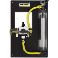
Station
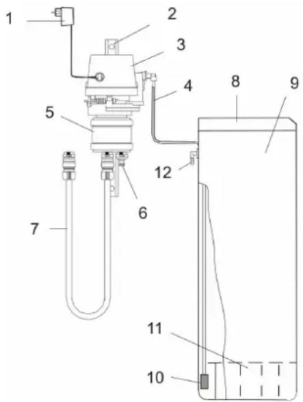
1 Power supply
2 Console
3 Control valve
4 Suction hose (red)
5 Adapter control valve
6 Connection WS 50 / WS 100 (2x)
7 Connection hose WS 50 / WS 100 (2x)
8 Lid, salt tank
9 Salt tank
10 Suction sieve
11 Sieve floor
12 Overflow
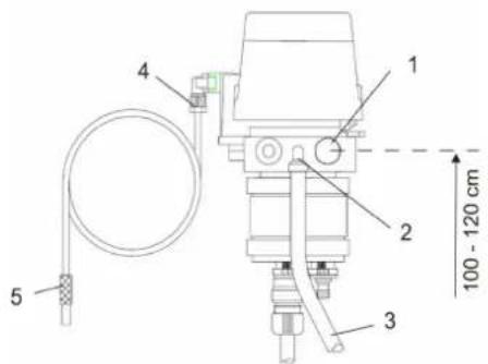
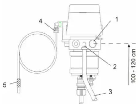
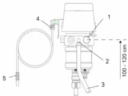
Connections
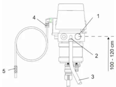
1 Connection raw water 1" IG (Installation height above the floor 100 - 120 cm) (Install stop valve in the inlet)
2 Connection 1/2" hose stem
3 Wastewater hose (not included in the scope of delivery)
4 Connection for red suction hose
5 Suction hose with suction strainer
Programming unit control valve
The activation of the programming unit takes place by pressing the red start button of the control valve.
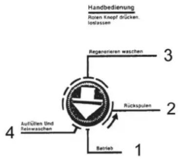
Figure: Programming unit control valve
The programming unit of the control valve has the following positions:
1 Operation
2 Backwash
3 Regenerate wash
4 Replenish and purge
Automatic programme sequence
The programming unit performs the regeneration and brings the control valve into positions 1 - operation.
Manual programme sequence
The individual programmes of the regeneration can also be selected manually.
→ Push the red programme button, turn in a counter-clockwise direction to the desired position.
Note: With position 4 - Replenish and purge ensure that this step is only performed if the salt tank has been drained by suction before.
Caution
→ At the end the programme button must not be set to positions 1 - operation as another regeneration will take place otherwise. At the end the programme button automatically moves back into position 1 - operation back.
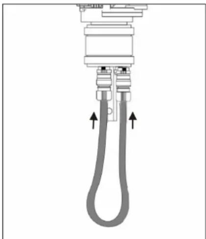
Initial startup
→ Connect both connections of the control valve adapter with the hose.
natural_image
Mechanical component diagram showing a coiled tube with two upward arrows indicating force or movement (no text or symbols present)Preparing WS regeneration station for operation
1 Close the stop valve of the water supply.
2 Remove the cover of the control valve. The programming unit (camshaft and control valve flaps) of the control valve becomes visible.
Bring the control valve into the "Operation, Position 1" position.
In order to do so, push the red programme button of the programming unit and simultaneously turn on the camshaft in a counter-clockwise direction until the arrow of the programme button is on "Operation, Position 1".
3 Open the stop valve of the water supply.
4 Bring the programme button into the "Backwash, Position 2" position by turning the camshaft.
Note: Water and air escape from the wastewater connection now. Continue to turn the programme button after approx. 1 minute.
5 Bring the programme button shortly before the "Replenish and purge, Position 4" position. In order to do so, push the red programme button of the programming unit and turn the camshaft in a counter-clockwise direction.
6 Allow the programming unit to automatically travel to the "Operation, Position 1" position.
Note: This takes approx. 15 minutes, within this time, the air seal valve fills with water and fills the salt tank via the suction hose.
If the "Operation, Position 1" position is reached, turn the programme button to the "Regenerate wash, Position 3" position. The control valve sucks and the water level in the salt tank slowly decreases until it is empty. Empty is equal to a water level of approx. 7 cm.
Important: If the salt tank is not completely drained by suction, the suction system is not sufficiently bled and there is air in the air seal valve. If this is the case, start over with step 5.
7 Finally bring the programme button shortly before the "Replenish and purge, Position 4" position and allow it to automatically move to the "Operation, Position 1" position.
Note: In the process, the salt tank is replenished. If the water is above the sieve bottom in the salt tank, the salt can be filled in.
8 Reattach the cover of the control valve.
9 Fill the water tank with at least 5 kg of salt.
Note: The salt tank can be completely filled, this does not increase the salt consumption.
Caution
→ Do not use cattle or road salt!
→ Only use salt in accordance with DIN 19604. Our salt meets these requirements (order no. 6.287-016.0 - 25 kg).
After completion of this work the WS regeneration station is ready for operation.
Regeneration
Regenerating WS 50 / WS 100
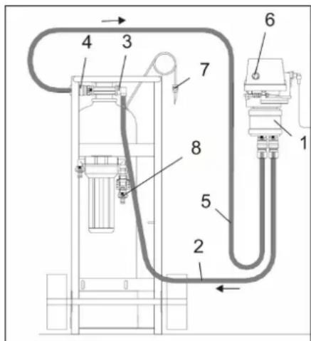
1 Control valve
2 Connection hose 1
3 Inlet exchanger
4 Outlet exchanger
5 Connection hose 2
6 Start button
7 Deaeration valve
8 Dial gauge
Connecting WS 50 / WS 100
→ Place the WS 50 or WS 100 next to the WS regeneration station.
→ Close the stop valve of the water supply.
→ Connect the connection hose 1 with the exchanger inlet and the control valve connection.
→ Connect the connection hose 2 with the exchanger outlet and the control valve connection.
→ Open the stop valve of the water supply.
→ Bleed the exchanger, in order to do so, open the bleed valve and allow the air to escape. Then close the valve.
Regeneration
→ Push the red start button. The regeneration is automatically performed by means of the programming unit of the control valve. Duration approx. 2 hours.
Note: The individual functions can also be selected manually, see Chapter "Programming unit control valve".
Caution
→ Always refill salt in due time, approx. 5 kg are consumed per regeneration.
→ Fill salt in when water is visible above the salt upon removing the cover at the latest.
→ If the salt tank is completely empty, the regeneration will not be successful
Disconnecting WS 50 / WS 100
After the regeneration has taken place:
→ Close the stop valve of the water supply.
→ Bleed the exchanger, in order to do so, open the bleed valve and allow the air to escape. Then close the valve.
→ Remove the connection hose 1 from the connection of the control valve and attach it to the dial gauge.
→ Remove the connection hose 2 from the exchanger and attach it to the control valve.
→ The regeneration is completed.
→ After the regeneration a soft water determination is to be performed.
See operating instructions WS 50 / WS 100 exchanger.
Maintenance and care
General notes
⚠️Danger
Risk of injury!
→ Always wear protective goggles when operating, maintaining and cleaning the appliance.
→ The plug connections are under pressure, depressurise the plant prior to detaching the plug connections.
Risk of frost
Caution
→ The station must not be exposed to frost. When setting up the station, the proper place must be selected.
Maintenance Works
Cleaning the salt tank
at least once a year:
→ Bring down the salt level in the salt tank until water is visible above the salt.
→ Remove the remaining salt.
→ Pull the suction hose with the suction strainer out of the guide tube.
→ Clean the entire container and reassemble it.
→ Perform initial start-up (see Chapter "Initial start-up") so that the suction system is bled and the salt tank is filled.
Injector control valve
As part of a maintenance, it is recommended to clean the injector and the injector sieve of the control valve.
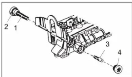
1 Injector sieve
2 O ring
3 Injector
4 Injector cap
→ Close the stop valve of the water supply.
→ Depressurise the system, in order to do so, set the programme button to the Position 2 - Backwash position.
→ Cleaning the injector sieve:
Unscrew and clean the injector sieve.
→ Grease the O-ring with silicone grease.
→ Cleaning the injector:
Unscrew the injector cap, pull the injector out using pliers and clean it.
→ Reinstall everything.
→ Open the stop valve of the water supply.
→ Bleeding the suction hose:
Perform initial start-up or press control valve flap 1.
Appendix
Detail control valve
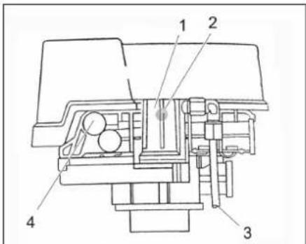
1 Air seal valve
2 Ball float
3 Suction hose (red)
4 Salt volume regulator
Pre-set, adjustment is not permitted
Control valve flaps
The control of the control valve flaps takes place via the cams on the camshaft (not shown) of the programming unit.
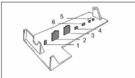
1 Saline solution (bleeding of the suction hose)
2 Inlet
3 Outlet
4 Bypass
5 Backwash/drain
6 Rinsing/drain
Function control valve flap
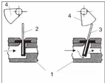
1 Valve casing
2 Valve flap closed
3 Valve flap open
4 Cam (camshaft)
Description air seal valve
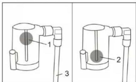
1 Ball float in open position
2 Ball float in closed position (air in the air seal valve)
3 Suction hose (red)
If the salt tank is empty, the suction hose draws air into the air seal valve. The ball float moves down and closes the valve.
→ Bleeding the air seal valve: Fill the salt tank, then perform initial start-up.
If air is caught in the air seal valve without the salt tank being empty, the suction system is not properly bled.
→ Bleeding the air seal valve: Repeat initial start-up from step 5.
Troubleshooting
⚠ Danger
Risk of electric shock!
→ Work on electrical plant only to be carried out by qualified and authorised electricians.
→ Pull out the connector plug on the appliance prior to performing any repair work.
⚠️Danger
Risk of injury!
→ The plug connections are under pressure, depressurise the plant prior to detaching the plug connections.
In case of a disturbance, check the salt tank first and top up salt if necessary.
→ If there has not been any salt left in the tank, wait at least 1 hour after replenishing until saline solution has formed.
→ Repeat regeneration.
→ By means of a soft water determination, check whether the exchanger has been regenerated.
See operating instructions WS 50 / WS 100 exchanger.
| Failure Cause Remedy | ||
| Control valve does not suck No water pres | sure Ensure a minimum pressure of 3 bar | |
| Injector or injector sieve clogged Cleaning | See Chapter "Maintenance work" | |
| Suction hose draws air Check screw connections | ||
| Suction hose with suction strainer soiled Cleaning | ||
| Dirt accumulation in the salt tank Cleaning the salt tank See Chapter "Maintenance work" | ||
| Wastewater hose clogged or kinked Check, clean or replace as necessary | ||
| Close control valve flap Call customer service. | ||
| Air in the air seal valve. As a result the ball float closes prematurely | Check connections of suction hose and sight glass | |
| Plant does not get any salt although the control valve is sucking | WS 50 / WS 100 Water level in the salt tank is too low and has no contact with the salt | Have the salt volume regulator set higher by the aftersales service See Chapter "Annex" |
| Resin leakage in operating position Lower | distributor nozzle on the rising pipe defective | Replace |
| Inlet and outlet of the plant interchanged Properly connect the connection hoses | ||
| No soft water in operation No salt in the salt | salt tank Filling the salt tank | |
| Regeneration has not taken place | Repeat regeneration. | |
| Disturbance in the suction system | Corrective actions as described above | |
| WS 50 / WS 100 The rising pipe in the resin tank is too short | Push the rising pipe in position or call the aftersales service | |
| WS 50 / WS 100 O-ring for rising pipe in the tank adapter of the control valve defective | Call customer service. | |
| Salt tank overflows | Salt volume regulator defective | Call customer service. |
| Programming unit defective | Call customer service. | |
| Control valve flap does not close Call customer service. | ||
| Plant does not suck, however it still fills | Injector or injector sieve clogged Cleaning | |
| Control valve is jammed and does not complete the regeneration | Programming unit defective | Call customer service. |
| Wastewater is constantly running | Foreign object in the control valve flap | Call customer service. |
www.kaercher.com/REACH
Garantie
natural_image
Diagram of a mechanical or fluidic device with a coiled pipe and valve, showing directional arrows (no text or symbols)www.kaercher.com/REACH
Garanzia
natural_image
Diagram of a mechanical or electrical component with two curved pipes and directional arrows indicating flow or movement (no text or symbols present)www.kaercher.com/REACH
Garantie
natural_image
Mechanical diagram showing a U-shaped pipe with two upward arrows indicating flow or movement (no text or symbols present)1 Regelventiel
1 Injectorzeef
2 O-ring
3 Injector
4 Injectorkap
www.kaercher.com/REACH
Garantía
natural_image
Diagram of a mechanical or electrical component with two curved pipes and directional arrows indicating flow or movement (no text or symbols present)1 Válvula de control
www.kaercher.com/REACH
Garantia
natural_image
Diagram of a mechanical or fluidic device with two hoses and directional arrows indicating flow or movement (no text or symbols present)1 Peneira do injector
2 O-Ring
3 Injector
4 Capa do injector
www.kaercher.com/REACH
Garanti
natural_image
Diagram of a mechanical or electrical component with two curved pipes and directional arrows indicating flow or movement (no text or symbols present)WS regenereringsstation forberedes til drift
1 Luk vandforsyningens spærreventil.
1 Styreventil
www.kaercher.com/REACH
Garanti
1 Strømforsyning
2 Konsoll
3 Styreventil
4 Sugeslange (rød)
5 Adapter styreventil
6 Tilkobling WS 50 / WS 100 (2x)
7 Tilkoblingsslange WS 50 / WS 100 (2x)
8 Deksel, salttank
9 Salttank
10 Sugesil
11 Silbunn
12 Overløp
Tilkoblinger
natural_image
Mechanical component diagram showing a coiled tube with two upward arrows indicating force or movement (no text or symbols present)1 Styreventil
2 Tilkoblingsslange 1
3 Inntak ionebytter
4 Utgang ionebytter
5 Tilkoblingsslange 2
6 Startknapp
7 Utluftingsventil
8 Mâleur
WS 50 / WS 100 tilkobling
1 Luftstengeventil
2 Flottørkule
3 Sugeslange (rød)
4 Saltmengderegulator
www.kaercher.com/REACH
Garanti
natural_image
Mechanical diagram showing a U-shaped pipe with two upward arrows indicating flow or movement (no text or symbols present)1 Styrventil
1 Injektorsil
2 O-ring
3 Injektor
4 Injektorkåpa
www.kaercher.com/REACH
Takuu
1 Jännitteensyöttö
2 Konsoli
3 Ohjausventtiili
4 Imuletku (punainen)
natural_image
Pure mechanical diagram showing a U-shaped pipe with two upward arrows indicating flow or force direction (no text or symbols)natural_image
Diagram of a mechanical component with two curved pipes and directional arrows indicating flow or movement (no text or symbols)www.kaercher.com/REACH
Garanti
natural_image
Mechanical diagram showing a U-shaped pipe with two upward arrows indicating flow or movement (no text or symbols present)1 Kumanda valfi
www.kaercher.com/REACH
Гарантия
natural_image
Diagram of a mechanical or fluidic device with two curved pipes and directional arrows indicating flow or movement (no text or symbols present)www.kaercher.com/REACH
Garancia
natural_image
Mechanical diagram showing a piston-cranked hydraulic cylinder with two upward arrows indicating flow direction (no text or labels)1 Vezérlő szelep
2 Összekötő tömlő 1
3 Cserélő bemenete
4 Cserél ö kimenete
5 Összekötő tömlő 2
6 Indító gomb
7 Szellőzőszelep
8 Mérőóra
www.kaercher.com/REACH
Záruka
natural_image
Mechanical diagram showing a U-shaped pipe with two upward arrows indicating flow or movement (no text or symbols present)1 Regulační ventil
natural_image
Pure mechanical diagram showing a U-shaped pipe with two upward arrows indicating flow or force direction (no text or symbols)Priprava WS regeneracijske postaje za obratovanje
1 Zaprite zaporni ventil oskrbe z vodo.
1 Kontrolni ventil
2 Povezovalna gibka cev 1
1 Zaporni ventil zraka
2 Krogelni plovec
3 Gibka sesalna cev (rdeča)
4 Regulator količine soli
Prednastavljeno, nastavljanje ni dovoljeno
1 Slanica (odzračevanje gibke sesalne cevi)
2 Dovod
3 Izpust
4 Obvod
5 Izpiranje/Odtok
6 Spiranje/Odtok
www.kaercher.com/REACH
Gwarancja
natural_image
Diagram of a mechanical or fluidic device with two hoses and directional arrows indicating flow or movement (no text or symbols present)1 Zawór sterujący
1 Filtr iniektora
2 O-ring
3 Iniektor
4 Kapturek iniektora
www.kaercher.com/REACH
Garantie
natural_image
Diagram of a mechanical device with two hoses and directional arrows indicating movement or force (no text or symbols)1 Supapă de comandă
2 Furtun de racord 1
1 Sită injector
2 Inel O
3 Injector
4 Capac injector
1 Napájanie napätím
2 Konzola
3 Riadiaci ventil
4 Sacia hadica (červená)
5 Adaptér riadiaceho ventilu
6 Prípojka WS 50 / WS 100 (2x)
7 Spojovacia hadica WS 50 / WS 100 (2x)
8 Kryt, nádrž na sol'
9 Nádrž na sol'
10 Sacie sitko
11 Dno sitka
12 Prepad
Prípojky

natural_image
Diagram of a mechanical or fluidic device with two hoses and directional arrows indicating flow or movement (no text or symbols present)1 Riadiaci ventil
1 Sitko injektora
2 Podložka
3 Vstrekovač
4 Kryt injektora
→ Uzavrite uzatvárací ventil napájania vodou.
→ Zbavte systém tlaku, presuňte k tomu programovacie tlačidlo do polohy 2 - Spätné vyplachovanie.
→ Čistenie sitka injektora:
1 S o l'anka (odvzdušnenie sacej hadice)
2 Vpust
3 Výpust
4 Obtok
5 Spätné vyplachovanie/Odtok
6 Vyplachovanie/Odtok
www.kaercher.com/REACH
Jamstvo
1 Napajanje električnom energijom
2 Konzola
3 Upravljački ventil
4 Usisno crijevo (crveno)
5 Prilagodnik upravljačkog ventila
6 Priključak WS 50 / WS 100 (2x)
7 Spojno crijevo WS 50 / WS 100 (2x)
8 Poklopac, spremnik za sol
9 Spremnik za sol
10 Usisno sito
11 Mrežasto dno
12 Preljev
Priključci
1 Priključak za potrošnu vodu 1" IG (Montažna visina iznad visine poda 100 - 120 cm) (instaliranje zapornog ventila u dovodu)
natural_image
Mechanical diagram showing a U-shaped pipe with two upward arrows indicating flow or movement (no text or symbols present)Priprema WS stanice za regeneraciju za rad
1 Zatvorite zaporni ventil dovoda vode.
2 Skinite poklopac upravljačkog ventila.
Programator upravljačkog ventila (grebenasta osovina i zaklopka upravljačkog ventila) je vidljiv.
1 Mrežica injektora
2 Brtveni prsten
3 Ubrizgavač
4 Kapica injektora
→ Zatvorite zaporni ventil dovoda vode.
→ Rastlačite sustav tako što ćete programski gumb postavite u položaj „2 - Povratno ispiranje“.
→ Čišćenje mrežice injektora:
1 Zaporni ventil za zrak
2 Plovak
3 Usisno crijevo (crveno)
4 Regulator količine soli
Tvornički namješten, nije dozvoljeno podešavanje
1 Otopina soli (odzračivanje usisnog cri-jeva)
2 Ulaz
3 Izlaz
4 Obilazni vod
5 Povratno ispiranje/ispust
6 Ispiranje/ispust
1 K u ćište ventila
2 Zaklopka ventila je zatvorena
3 Zaklopka ventila je otvorena
4 Greben (grebenasta osovina)
www.kaercher.com/REACH
Garancija
U svakoj zemlji važe garantni uslovi koje je izdala naša nadležna distributivna organizacija. Eventualne smetnje na uređaju za vreme trajanja garancije uklanjamo besplatno, ukoliko je uzrok greška u materijalu ili proizvodnji. U slučaju koji podleže garanciji obratite se sa potvrdom o kupovini Vašem prodavcu ili najbližoj ovlašćenoj servisnoj službi.
Rezervni delovi
Upotrebljavajte samo originalne rezervne delove firme KÄRCHER. Pregled rezervnih delova naci ćete na kraju ovog uputstva za rad.
Simboli u uputstvu za rad
⚠️ Opasnost
Ukazuje na neposredno preteću opasnost koja dovodi do teških telesnih povreda ili smrti.
⚠Upozorenje
Ukazuje na eventualno opasnu situaciju koja može dovesti do teških telesnih povreda ili smrti.
Oprez
Ukazuje na eventualno opasnu situaciju koja može dovesti do lakših telesnih povreda ili izazvati materijalnu štetu.
Sigurnosne napomene
1 Napajanje električnom energijom
2 Konzola
3 Upravljački ventil
4 Usisno crevo (crveno)
5 Adapter upravljačkog ventila
6 Priključak WS 50 / WS 100 (2x)
7 Spojno crevo WS 50 / WS 100 (2x)
8 Poklopac, rezervoar za so
9 Rezervoar za so
10 Usisna mrežica
11 Mrežasto dno
12 Preliv
Priključci

1 Priključak za potrošnu vodu 1" IG (Montažna visina iznad visine poda 100 - 120 cm) (instaliranje blokirnog ventila u dovodu)
natural_image
Mechanical diagram showing a U-shaped pipe with two upward arrows indicating flow or movement (no text or symbols present)Priprema WS stanice za regeneraciju za rad
1 Zatvorite blokirni ventil dovoda vode.
2 Skinite poklopac upravljačkog ventila. Programator upravljačkog ventila (bregasta osovina i zaklopka upravljačkog ventila) je vidljiv. Upravljački ventil okrenite u položaj „Rad, položaj 1“.
U tu svrhu pritisnite crveno programsko dugme programatora i istovremeno okrenite na bregastoj osovini ulevo, tako da strelica dugmeta pokazuje na „Rad, položaj 1“.
3 Otvorite blokirni ventil dovoda vode.
4 Okrenite bregastu osovinu pa programsko dugme postavite u položaj „Povratno ispiranje, položaj 2“.
Napomena: Voda i vazduh izlaze kroz kanalizacioni priključak. Nakon oko 1 min okrenite dalje programsko dugme.
5 Programsko dugme postavite nešto ispred položaja „Punjenje i čisto pranje, položaj 4“. U tu svrhu pritisnite crveno programsko dugme programatora pa bregastu osovinu okrenite ulevo.
6 Pustite programator da se sam okrene u položaj „Rad, položaj 1“.
Napomena: To traje oko 15 min i tokom tog vremena se blokirni ventil za vazduh puni vodom i uz pomoć usisnog creva puni rezervoar za so.
Nakon što se dostigne položaj „Rad, položaj 1“, okrenite programsko dugme u položaj „Regeneraciono pranje, položaj 3“. Upravljački ventil usisava tako da nivo vode u rezervoaru za so polako opada dok ga ne isprazni. Rezervoar je prazan kada je nivo vode oko 7 cm.
1 Blokirni ventil za vazduh
2 Plovak
3 Usisno crevo (crveno)
4 Regulator količine soli
Fabrički namešten, nije dozvoljeno
podešavanje
1 Rastvor soli (ispuštanje vazduha iz usisnog creva)
2 Ulaz
3 Izlaz
4 Obilazni vod
5 Povratno ispiranje/ispust
6 Ispiranje/ispust
www.kaercher.com/REACH
Гаранция
natural_image
Diagram of a mechanical or fluidic device with two hoses and directional arrows indicating flow or movement (no text or symbols present)1 Управляващ вентил
2 Свързващ маркуч 1
3 Вход обменник
4 Изход обменник
5 Свързващ маркуч 2
www.kaercher.com/REACH
Garantii
natural_image
Mechanical component diagram showing a coiled tube with two upward arrows indicating force or movement (no text or symbols present)1 Juhtventiil
2 Ühendusvoolik 1
3 Vaheti sisend
4 Vaheti väljund
5 Ühendusvoolik 2
6 Stardinupp
7 Ôhutusventiil
8 Indikaatorkell
1 Pihusti söel
2 O-tihend
3 Pihusti
4 Pihusti kork
www.kaercher.com/REACH
Garantija
natural_image
Diagram of a mechanical or electrical component with two curved pipes and directional arrows indicating flow or movement (no text or symbols present)1 Vadības vārsts
2 Savienojuma šljutene 1
www.kaercher.com/REACH
Garantija
1 Maitinimas
2 Blokas
3 Valdymo vožtuvas
4 Siurbimo žarna (raudona)
5 Valdymo vožtuvo adapteris
6 Jungtis WS 50 / WS 100 (2x)
7 Jungiamoji žarna WS 50 / WS 100 (2x)
8 Dangtis, druskos talpykla
9 Druskos bakas
10 Siurbimo filtras
11 Sieto dugnas
12 Vandens nupiltuvas
Jungtys
natural_image
Pure mechanical diagram showing a U-shaped pipe with two upward arrows indicating flow or movement (no text or symbols)1 Valdymo vožtuvas
2 1 jungiamoji žarna
3 Keitiklio įvadas
4 Keitiklio išvadas
5 2 jungiamoji žarna
natural_image
Diagram of a mechanical or fluidic device with two curved pipes and directional arrows indicating flow or movement (no text or symbols present)1 Клапан керування
http://www.kaercher.com/dealersearch
71364 Winnenden (Germany)
Tel.: +49 7195 14-0
Fax: +49 7195 14-2212