
WRP 1000 Classic - Water filter Kärcher - Free user manual and instructions
Find the device manual for free WRP 1000 Classic Kärcher in PDF.
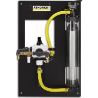


| Product type | Water filter for washing installation |
| Brand | Kärcher |
| Model | WRP 1000 Classic |
| Dimensions (L × W × H) | 660 mm × 470 mm × 980 mm |
| Weight | 45 kg |
| Nominal flow rate | 1000 l/h |
| Operating pressure | 0.2 – 0.35 MPa (2 – 3.5 bar) |
| Supply | Connection to site submersible pump (not supplied) |
| Main functions | Filtration of oil-free wastewater, backwashing, service water circulation, frost protection |
| Filter type | Filament filter |
| Intended use | Treatment of vehicle wash wastewater for reuse |
| Maintenance and cleaning | Daily backwashing, weekly cleaning of the collector, monthly draining of the service water tank, annual replacement of the filter cartridge |
| Safety | Shut down submersible pump before any intervention; use by qualified personnel; frost protection |
| Spare parts and repairability | Filter element (p/n 5.033-239.0), fresh water switching kit (p/n 2.641-521.0) |
| General information | Installation reserved for Kärcher specialists; warranty according to local conditions |
Frequently Asked Questions - WRP 1000 Classic Kärcher
User questions about WRP 1000 Classic Kärcher
0 question about this device. Answer the ones you know or ask your own.
Ask a new question about this device
Download the instructions for your Water filter in PDF format for free! Find your manual WRP 1000 Classic - Kärcher and take your electronic device back in hand. On this page are published all the documents necessary for the use of your device. WRP 1000 Classic by Kärcher.
USER MANUAL WRP 1000 Classic Kärcher
Czech 82
Slovenian 87
Polish 92
Romanian 98
Slovak 104
Croatian 109
Serbian 114
Bulgarian 119
Estonian 125
Latvian 130
Lithuanian 135
Ukrainian 140
1 clamping lever
1 nut
2 clamping levers
1 Nutenstein
Please read and comply with these original instructions prior
to the initial operation of your appliance and store them for later use or subsequent owners.
Contents
About this Operations Manual EN .. 1
Environmental protection .. EN .. 1
Warranty ..... EN .. 1
Safety instructions ..... EN .. 1
Operation ..... EN .. 1
Transport ..... EN .. 2
Storage....EN..2
Function ..... EN .. 2
Technical specifications ... EN .. 2
Maintenance and care .... EN .. 3
Troubleshooting ..... EN .. 5
Accessories ..... EN .. 5
Installing the unit (only for experts). EN . 5
About this Operations Manual
Target group for these instructions
About this Operations Manual
– All users: Users include trained auxiliary personnel, operators and experts.
- Experts: Experts are individuals who, according to their professional education, are able to install the equipment and to operate it.
Definitions
Fresh water
Tap water
Waste water
Dirty water discharged from the high-pressure cleaner washing unit
Processed water
Water prepared by the system for reuse in the washing programmes (preliminary washing, brush washing, high pressure cleaning, underbody cleaning) in the vehicle washing system or the high-pressure cleaner.
Environmental protection

The packaging materials are recyclable. Please do not throw packaging in the domestic waste but pass it on for recycling.

Old units contain valuable recyclable materials. Batteries, oil and similar substances may not be released into the environment. Therefore please dispose of old units through suitable collection systems.
Notes about the ingredients (REACH)
You will find current information about the ingredients at:
www.kaercher.com/REACH
Warranty
The warranty terms published by our competent sales company are applicable in each country. We will repair potential failures of your appliance within the warranty period free of charge, provided that such failure is caused by faulty material or defects in fabrication. In the event of a warranty claim please contact your dealer or the nearest authorized Customer Service center. Please submit the proof of purchase.
Safety instructions
Symbols used in the operation instruction
The following symbols are used in this operating manual:
⚠️Danger!
Indicates an immediate danger. By not paying attention to this notice, there is danger of death or serious injury.
⚠ Warning
Indicates a possible dangerous situation.
By not paying attention to the notice, light injuries or property damage may possibly occur.
Notice
Indicates operating idea and important information.
General
To avoid danger to persons, animals and property before the first operation of the system, read:
– this operating instructions manual, especially the safety instructions contained therein – the enclosed "Safety instructions for waste water treatment plants" – the respective national statutes of the legislator. All individuals who are involved in the installation, operation, maintenance, and service of this equipment must: – have the requisite qualifications, – know and observe the "Safety instructions for waste water treatment plants", – know and have read this operations manual, – know and follow the corresponding regulations.
The appliance may only be used by persons who have been instructed in handling the appliance or have proven qualification and expertise in operating the appliance or have been explicitly assigned the task of handling the appliance.
This appliance is not intended for use by persons with reduced physical, sensory, or mental capabilities.
The appliance must not be operated by children or persons who have not been instructed accordingly.
⚠️ Danger
Do not drink the processed water - health hazard. The cleaned waste water is not of potable quality. It still contains some residues of dirt and detergents.
Proper use
The system cleans oil-free dirt water discharged from vehicle cleaning and provides processed water to the high-pressure cleaner or the vehicle washing systems that have low water consumption (max. 1000 litres per hour). The used water can only be used for cleaning programmes (for e.g. preliminary washing, high pressure cleaning, brush cleaning). Processed water is not suitable for use as rinsing water or for applying drying aid or some other such purpose.
Cleaning is done by:
- Separating heavy parts that easily settle down in the gravel filter. Pre-requisites for smooth functioning:
- Basin system according to the water flow diagram shown in the "Function" chapter. – Oil-free waste water in circulation in the system.
Operation
Operating elements
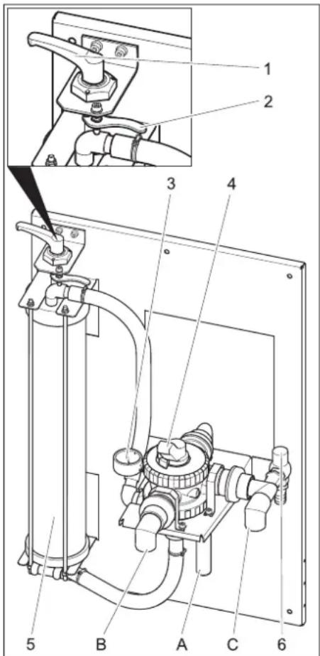
1 Tension lever 2 Unlocking lever 3 Manometer at the filter inlet 4 Multi-channel valve 5 Filament filter 6 Overflow valve
A to collect sludge (rinse back) B to the high-pressure cleaner / processed water tank (filling) C from the immersion pump
Adjust the filter pre-tension
Proceed as follows to subsequently change the filter tension:
→ Turn the tension lever to the left until the lever reaches the stop. → Pull the unlocking lever towards the front and turn the tightening lever toward the right until the unlocking lever locks in in the next nose.
Filter operations
→ Turn the lever of the multi-channel valve in "FILTRATION" position.
Note
After longer idling times it takes a lot of effort to activate the multi-channel valve.
→ Check filter pre-tension. → Start the pump in the building.
Backwash
Note
During normal operations, you must backwash the filter at least once daily. The system does not release any processed water during the back-rinsing process.
During backwash, the dirt collected in the filament filter is removed. To do this, the filament filter is rinsed in the reverse direction. According to local regulations, the rinsed-out dirt is either directed into the sludge collection of the recycling system, an existing disposal chain, or the drainage.
→ Start the pump in the building. → Turn the lever of the multi-channel valve to the "RÜCKSPÜLEN/BACKWASH" position. → Loosen the filament filter by turning the tension lever counterclockwise. → Wait for 30 seconds. → Tighten the filament filter and loosen it immediately. → Repeat this process of waiting for 10 minutes, tightening, and loosening ten times. → Reset the filter pre-tension. → Turn the lever of the multi-channel valve to the "ERSTFILTRAT/RINSE" position. → Wait 2 minutes. → Turn the lever of the multi-channel valve to the "FILTRATION" position.
Processed water circulation
If the high-pressure cleaner or the washing system does not use up the water, the processed water is circulated to avoid foul odors.
Note
The immersion pump can be periodically switched on/off during non-operating hours (e.g., at night, over the weekend) to lower the operating hours. For this, you can connect the immersion pump via a timer to the power supply.
Maximum interval increment: 1 hour.
Frost protection
The plant must be operated in frost-free rooms. During frost, put the system out of operation and remove all traces of water:
→ Pull out the hoses. → Let the system dry-run.
Shutdown
→ Switch off the building pump. → If there is a risk of frosting, then any existing water traces must be removed (see section "Anti-freezing").
Transport
Caution
Risk of injury and damage! Observe the weight of the appliance when you transport it.
When transporting in vehicles, secure the appliance according to the guidelines to prevent slipping and tipping over.
Storage
Caution
Risk of injury and damage! Note the weight of the appliance when storing.
Function
Flow pattern
![graph TD 1["Component 1"] --> 2["Component 2"] 2 --> 3["Component 3"] 3 --> 4["Component 4"] 4 --> 5["Component 5"] 5 --> 6["Component 6"] 6 --> 7["Component 7"] 7 --> 8["Component 8"] 8 --> 9["Component 9"] 9 --> 10["Component 10"] 10 --> 11["Component 11"] 11 --> 12["Component 12"] 12 --> 13["Comp…](/content/2026/03/557400/images/7e020464584ad3f8c456ed754e17f03fc5a048bcf2c13beb0123d4e573d1045e.jpg)
1 Filament filter
2 Multi-channel valve
3 Manometer at the filter inlet
4 Overflow valve
5 Backwash pipe
6 Circulation (to sludge collector)
7 To the processed water tank/ high-pressure cleaner
8 Sludge collection of the recycling system *)
9 Pump basin of the recycling system *)
10 Immersion pump *) 11 Separation system (EN 858) *) 12 Control shaft *) 13 to drainage system *) *) on building side
Functional description
The following section describes the flow-path of the water in different positions of the multi-channel valve.
FILTRATION
In filter operations, the water flows via
- Immersion pump
- Multi-channel valve in "FILTRATION" position
- Filter (flow direction of filtering)
- To the high-pressure cleaner/processed water tank
BACKWASH
During backwash, the water flows via
- Immersion pump
- Multi-channel valve in position "BACKWASH"
- Filter (against flow direction of filtering)
- To the sludge collector
FIRST FILTRATE/RINSE
During final rinse the water flows via:
- Immersion pump – Multi-channel valve in position FIRST FILTRATE/RINSE
- Filter (flow direction of filtering)
- To the sludge collector
RECIRCULATION
This position is not required for operating the system.
Technical specifications
| WRP1000eco | WRP1000compact | ||
| Pressure (min.) | MPa(bar) | 0,2 (2) | |
| Pressure(max.) | MPa(bar) | 0,35 (3,5) | |
| Filter capacity l/h | 1000 | ||
| Width mm 660 | |||
| Depth mm 470 | |||
| Height mm 980 | 1230 | ||
| Weight | kg | 45 | |
Immersion pump requirements (building-side)
| Pressure (min.) MPa | (bar) | 0,2 (2) |
| Pressure (max.) MPa | (bar) | 0,35(3,5) |
| Minimum flow rate at 0.2 MPa (2 bar) | l/h | 1000 |
- Suitable for dirty water – Suitable for continuous operation – With protection against dry-running
Maintenance and care
Maintenance instructions
The basis for safe operation of the equipment is regular maintenance according to the following maintenance plan. Use only original parts of the manufacturer or parts recommended by them, such as
- parts and wearing parts,
- accessory parts, – operating materials,
- cleaning agents.
⚠️ Danger
Risk of accident while working on the unit. During all tasks
→ Shut off water supply. → Switch off the immersion pump in the building.
Who may perform maintenance?
- Operator
Tasks marked with "operator" may only be performed by instructed individuals who are able to operate and service high-pressure equipment.
- Maintenance
Tasks marked with "maintenance" may only be performed by Kärcher maintenance mechanics.
Maintenance contract
To guarantee reliable operation of the equipment, we recommend that you sign a maintenance agreement. Please contact your local Kärcher service department.
Maintenance schedule
| Time Activity Assembly affected | Performance By whom | |||
| daily Backwash Filament filter Run bachwash Operator | ||||
| weekly Clean the filter | Drain at washing place | Clean the dirt collection basket in the floor. Operator | ||
| opinion Detector concentration in processed water | Reduce the detergent dosing at the detergent dispenser if there is foam formation. | Operator | ||
| monthly | opinion Sludge collection, pump basin | After sludge has been collected, there should be no sludge in any of the basins. The sludge in the sludge collector should be maximum 1 m in height. Check sludge level; pump out and dispose off the sludge according to the local regulations, if required. | Operator | |
| empty, clean | Processed water tank (if available) | Empty, clean, rinse and refill. | Operator | |
| Half-yearly (if required) | Change water, clean the basins | Sludge collection, oil separator, pump basin | Empty the basins, remove sludge completely and fill the basin with fresh water. Store the waste disposal documents. | Operator/ Disposal agency |
| annual | Exchange filter | Filter inlay | Replace filter inlay of the filament filter. | Operator/ Customer Service |
Replacing filter inlay
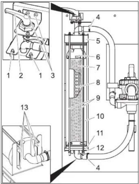
1 Nut
2 Tension lever
3 Screw of the tension lever bearing
4 Hose clip
5 Cover
6 Upper section
7 Filter inlay
8 Filtrate pipe
9 Threaded rod
10 Filament filter
11 Lower part
12 Lower console
13 Pin
→ Unlock filter. → Open the hose clamps. → Pull the hoses off the hose fittings. → Turn out both the screws of the tension lever bearing. → Lift upward the entire tension lever along with the bearings. → Unscrew the nuts at the upper end of the threaded rods. → Remove the threaded rod assembly. → Pull out the filament filter towards the front. → Remove the lid of the filament filter. → Pull out the lower part of the filament filter including filter inlay.
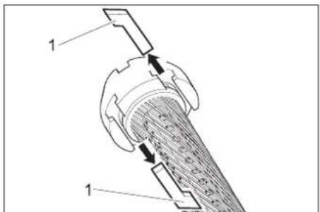
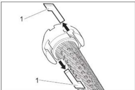
1 Grooved stone
→ Pull out the grooved stones between the upper part and the filter inlay and between the lower part and the filter inlay. → Remove upper and lower part of filter inlay. → Remove filtrate pipe from filtrate inlay. → Dispose of the filter inlay. → Attach filtrate pipe at one end of the new filter inlay. → Tighten the filter inlay in such a way that the filaments do not twist. → Push the filtrate pipe in the filter inlay and by looking at the opposite side of the filter element push the inlay in the direction of the filtrate pipe. → Coat all rings with normal liquid soap before carrying out any further installation tasks.
Note
Do not use silicon grease. Silicon in water will hamper the cleaning and drying effect during vehicle wash.
→ Insert the upper and lower part on the filter element. → Align the upper and lower part in such a way that the grooved stones can be inserted.
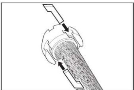
→ Insert the grooved stones and clamp it tight by slightly turning the filter inlay. → Insert the lower part into the filament filter and push it in completely. → Replace the filament filter lid. → Place the filament filter on the lower console so that both the rear pins lock into the long-holes of the console.
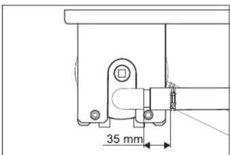
→ Align the lid, as shown above, and push it in completely. → Push in the filament filter between the two consoles. → Hook in the threaded rod assembly at the lower console and insert the threaded rods through the holes in the upper console. → Fasten the threaded rods with underlay washers and nuts.
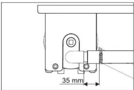
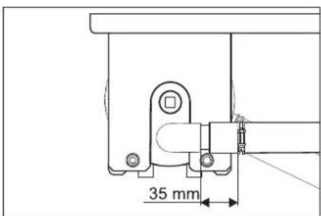
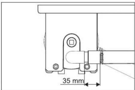
→ Tighten the nuts in such a way that the underlay washers can be still be moved by hand. → Insert the hoses onto the hose fittings. → Tighten the hose clamps (keep the 35 mm distance). → Insert the tension lever with bearing through the lid of the filament filter.
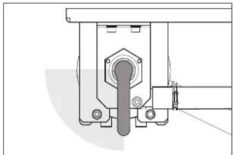
→ Turn the tightening lever in clockwise direction. It should be possible to turn the tightening lever in the range shown above without exerting any pressure. Otherwise, dismantle the tightening lever and insert it again in the correct position. → Fasten the tension lever bearings with screws. → Adjust the filter pre-tension.
Troubleshooting
⚠ Danger
Risk of accident while working on the unit. During all tasks
→ Switch off the immersion pump in the building.
Who may remedy faults?
- Operator
Work designated with the sign "Operator" may only be carried out by persons who have been instructed in the safe operation and maintenance on the wash plant
- Customer Service
Work designated with the sign "Customer Service" may only be done by the fitters of Kärcher Customer Service or fitters who have been authorised by Kärcher.
| Fault Possible cause | Remedy By whom | ||
| Plant out of order Power supply to the pump in the building is interrupted. | Check power supply and ensure proper supply. Operator | ||
| Processed water is coloured or is foaming too much | Filter pre-tension is not correct. Adjust the filter pre-tension Operator | ||
| Filter inlay is defective (leaky) Replacing filter inlay Operator, Cus- | tomer Service | ||
| Sludge collector or pump basin is dirty Emptying and cleaning the basins Operator/ Dis- | posal agency | ||
| Improper detergents are used in the washing unit or washing hall | Use compatible detergents; rinse the system, if necessary | Operator, Cus-tomer Service | |
| Detergent dosing in the washing unit is too high | Check detergent dosing; reset, if necessary Operator, Cus-tomer Service | ||
| Washing place cleaned with incompatible detergents | Replace water and rinse the basins Operator | ||
| Filter output is too low | Filament filter is blocked | Backwash filament filter; replace filter inlay if required. | Operator |
| Immersion pump is of lesser dimension | Install a suitable immersion pump (see requirements under "Technical Data") | Operator | |
| Immersion pump is blocked, defective | Clean, repair, replace immersion pump | Operator, Cus-tomer Service | |
| Pipe or valve is leaky, defective, blocked | Check pipes and valves; clean, repair or replace as required | Operator, Cus-tomer Service | |
Accessories
Filter inlay
| Order number | 5.033-239.0 |
Attachment set 'Fresh water switching'
| Order number | 2.641-521.0 |
Manual switching between processed/fresh water for using fresh water in the high-pressure cleaner (e.g., for rinsing).
Installing the unit (only for experts)
Notice
The equipment may only be installed by a Kärcher mechanic or an individual authorized by Kärcher.
Preparing the installation place
The following requirements are necessary in order to install the equipment:
- Frost-free room with adequate ventilation and exhausts – Floor path for collecting sludge – Strong wall for fastening the system
Unpack the equipment
Unpack the equipment and dispose of the packing material properly.
Water installation
The water installation depends on the specific conditions of the existing plant components such as
- Type and model of high-pressure cleaner or washing system
Note
The processed water outlet of the system is directly connected to the water inlet of the high-pressure cleaner. This can lead to foam formation in the swimmer tank in high-pressure cleaners with a swimmer tank. In such a case, the high-pressure cleaner must be switched to suction operations (see separate operating instructions of the high-pressure cleaner).
- Type and models of building-side components (sludge collector, pump basin, etc.) – Nominal width, lengths and type of channels
Hence, the water installation must be done according to the specific local conditions. The immersion pump specifications in the building must meet the requirements outlined in the "Technical Data / Immersion Pump Requirements" section.
⚠️Danger
Risk of injury on account of tripping and falling. Lay the hoses of the plant in such a way that they do not pose a risk for tripping and falling.
1 Clamping lever
1 Slide
1 Nut
1 Grooved nut
1 Tension lever 2 Release lever 3 Pressure gauge filter inlet 4 Multi-way valve 5 Wire filter 6 Overflow valve
1 Lever
2 Tension lever
3 Screw bearing tension lever
4 Hose clamp
5 Cover
6 Upper part
7 Filter element
8 Filtrate tube
1 T-nut
www.kaercher.com/REACH
Warranty
1 nut
1 Sliding nut
www.kaercher.com/REACH
Warranty
1 Screw
2 Tensioning lever
1 Latch
www.kaercher.com/REACH
Warranty
1 Nut
2 Clamping handle
1 Notch
www.kaercher.com/REACH
Warranty
1 Tensioning lever
2 Locking lever
3 Pressure gauge inlet
4 Multi-way valve
5 Filament filter
6 Overflow valve
A To the dirt trap (backwashing)
Setting the filter preload
During backwashing, the water flows through:
- Suction pump
- Multiport valve in "PRE-FILTERING/RINSE" position
- Filter (flow direction filters)
- in the dirt trap
CIRCULATION/RECIRCULATION
1 Nut
2 Tension lever
3 Tension lever bearing screw
4 Hose clamp
5 Cover
6 Top part
7 Filter insert
8 Filter tube
9 Threaded bolt
10 Filament filter
11 Lower part
12 Lower console
13 Pin
1 Mounting block
www.kaercher.com/REACH
Warranty
1 Tension arm
2 Locking lever
1 Nut
2 Tension arm
1 Notch block
www.kaercher.com/REACH
Warranty
1 Nut
2 Clamping lever
1 T-slot clamp
1 Clamping lever
1 Nut
2 Clamping lever
1 Tab
www.kaercher.com/REACH
Warranty
1 Tension lever
2 Release lever
3 Pressure gauge; filter inlet
4 Multi-way valve
5 Fiber filter
6 Discharge valve
1 Nut 2 Tension lever 3 Tension lever bearing bolt 4 Hose clamp 5 Cover 6 Upper part 7 Filter cartridge 8 Filtrate pipe 9 Toothed rod 10 Fiber filter 11 Lower part 12 Lower console 13 Pin
1 Grooved stone
www.kaercher.com/REACH
1 Clamping handle
1 Nut
2 Clamping handle
www.kaercher.com/REACH
Warranty
1 Tension lever
2 Release lever
1 Nut
2 Tension lever
1 Sliding block
www.kaercher.com/REACH
Warranty
1 Clamping lever
2 Release lever
1 Nut
2 Clamping lever
1 Guide insert
1 Tensioner
2 Release handle
3 Filter inlet pressure gauge
4 Inlet valve
5 Filament filter
6 Overflow valve
A in dirt trap (backwash)
1 Nut
2 Tensioner
3 Tensioner bearing screw
4 Flexible hose clamp
5 Cover
6 Upper part
7 Filter element
8 Filtrate hose
9 Threaded rod
10 Filament filter
11 Lower part
12 Lower bracket
13 Pin
→ Release the filter. → Open the flexible hose clamps. → Remove the flexible hoses from the flexible hose connectors. → Unscrew both tensioner bearing screws. → Remove the tensioner together with the bearing upwards. → Unscrew the nuts on the upper end of the threaded rod. → Remove the threaded rod assembly. → Pull the filament filter forward. → Remove the cover of the filament filter. → Remove the lower part of the filament filter together with the filter element.
1 Slotted screw nut
→ Pull out the slotted screw nuts between the upper part and the filter element, and between the lower part and the filter element.
→ Insert the screw nuts into the slot and tighten them with a slight turn of the filter cartridge. → Insert the lower part into the filament filter and push it all the way in. → Place the cover on the filament filter. → Place the filament filter on the lower bracket so that both rear pins sit in the horizontal holes of the bracket.
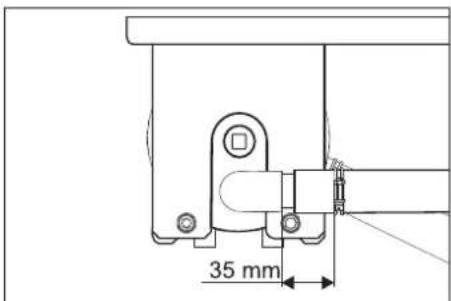
→ As shown above, align the cover and push it fully in. → Push the filament filter between the two brackets. → Attach the threaded rod assembly with the hook to the lower bracket and insert the threaded rods through the holes in the upper bracket. → Secure the threaded rods with washers and nuts. → Tighten the nuts so that the washers can still be moved by hand. → Slide the flexible hoses onto the flexible hose connectors. → Tighten the flexible hose clamps (observe the 35 mm distance).
→ Insert the tensioner with its bearing through the cover of the filament filter.
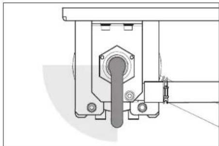
→ Turn the tensioner clockwise. The tensioner must be able to be turned without effort into the area shown above. Otherwise, disassemble the tensioner and reinsert it in a corrected position. → Secure the tensioner bearing with both screws. → Set the filter pre-tension.
Troubleshooting
⚠️ Danger
www.kaercher.com/REACH
Warranty
1 Nut
1 Locking stone
www.kaercher.com/REACH
Warranty
1 Tensioning handle
1 Slide
www.kaercher.com/REACH
Warranty
1 Clamping lever
2 Release lever
3 Pressure gauge at filter inlet
4 Multi-way valve
5 Fiber filter
6 Bypass valve
1 Nut
2 Clamping lever
1 Guide insert
→ Insert the guide inserts and secure them by turning the filter insert slightly. → Insert the bottom part into the fiber filter and push it all the way in. → Place the lid on the fiber filter. → Place the fiber filter on the bottom bracket so that both rear pins engage in the longitudinal slots of the bracket.
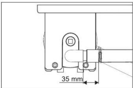
www.kaercher.com/REACH
Warranty
1 Clamping lever
2 Release lever
3 Pressure gauge, filter inlet
1 Nut
2 Clamping lever
3 Bearing screw for clamping lever
4 Hose clamp
5 Cover
6 Upper part
7 Filter insert
8 Filtrate pipe
9 Threaded rod
10 Fiber filter
11 Lower part
12 Lower bracket
13 Pin
→ Loosen the filter. → Open the hose clamps. → Remove the hoses from the hose connections. → Unscrew both bearing screws of the clamping lever. → Remove the clamping lever together with the bearing upwards. → Unscrew the nuts at the upper end of the threaded rod. → Remove the threaded rod assembly. → Pull the fiber filter forward. → Remove the cover of the fiber filter. → Remove the lower part of the fiber filter together with the filter insert.
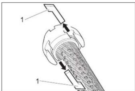
1 Elements with grooves
→ Insert the elements with grooves and secure the filter insert with a slight turn. → Place the lower part into the fiber filter and push it in completely. → Place the cover on the fiber filter. → Position the fiber filter on the lower bracket so that both rear pins fit into the longitudinal holes of the bracket.
→ Center the cover as shown above and push it in completely. → Push the fiber filter between both brackets. → Hook the assembly with threaded rods onto the lower bracket and insert the threaded rods through the holes in the upper bracket. → Secure the threaded rods with washers and nuts. → Tighten the nuts only enough so that the washers can still be moved by hand. → Connect the hoses to the hose connections.
→ Tighten the hose clamps (maintain a distance of 35 mm). → Insert the clamping lever with its seat through the cover of the fiber filter.
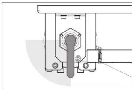
→ Turn the clamping lever clockwise. The clamping lever must be able to rotate without force in the area shown above. Otherwise, disassemble the clamping lever and reposition it in the corrected position. → Secure the clamping lever seat with both screws. → Adjust the filter pre-tension.
Troubleshooting assistance
⚠️ Danger
Risk of injury when working on the machine. For all work
www.kaercher.com/REACH
Warranty
In every country, the warranty conditions issued by our responsible distribution organization apply. We will rectify any faults on the device free of charge during the warranty period, provided the cause is a material or manufacturing defect. In the event of a warranty claim, please contact your dealer or the nearest authorized service center with your proof of purchase.
Safety notes
Symbols in the operating instructions
1 To the recycled water tank 2 Release lever 3 Pressure gauge, filter inlet 4 Multi-way valve 5 Filament filter 6 Overflow valve
A To the sludge remover (backwash) B To the high-pressure cleaning device / fresh water tank (filling) C From the submersible pump
Filter pre-tension adjustment
To subsequently adjust the filter tension, proceed as follows:
→ Turn the tension handle to the left as far as it will go. → Pull the release lever towards you and turn the tension handle to the right until the release lever engages in the next notch.
Filter drive
→ Turn the multi-port valve lever to the "FILTERING" position.
Note
After the device has been idle for a longer period, greater force may be required to activate the diverter valve.
1 Union nut
2 To recycled water tank
3 Bearing screw for tension lever
4 Hose clamp
5 Cover
6 Upper part
7 Filter cartridge
8 Filter tube
9 Threaded rod
10 Filament filter
11 Lower part
12 Lower console
13 Wedge
→ Loosen the filter. → Open the hose clamp. → Pull the hoses out of the pipe connections. → Unscrew both screws of the tension lever bearing. → Remove the tension lever together with the bearing upwards. → Unscrew the nuts on the upper end of the threaded rods. → Remove the threaded rod assemblies. → Pull the filament filter forward. → Remove the filament filter cover. → Remove the lower part of the filament filter together with the filter insert.
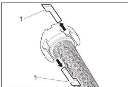
1 Stone grooves
→ Pull the stone grooves out between the upper part and the filter insert and between the lower part and the filter insert. → Remove the upper part and the lower part from the filter insert. → Pull the filter tube out of the filter insert, → remove the filter insert. → Place the filter tube on the end of the new filter insert. → Tension the filter insert so that the filaments are not twisted. → Push the filter tube into the filter insert and, while doing so, guide the direction of the filter tube by looking at the opposite side of the filter element. → Before further assembly, coat all O-rings with the usual liquid soap.
Note
Do not use silicone grease. Silicone in water reduces the cleaning and drying result when washing vehicles.
→ Insert the stone grooves and tighten them with a slight rotation of the filter insert. → Place the lower part into the filament filter and push it in completely. → Place the cover on the filament filter. → Put the filament filter on the lower console so that both rear pins are in the long holes of the console.
→ Straighten the cover as shown above and push it in completely. → Push the filament filter between the two consoles. → Hang the threaded rod assemblies on the lower console and insert the threaded rods through the openings in the upper part of the console. → Secure the threaded rods with washers and nuts. → Tighten the nuts so firmly that the washers can still be moved by hand.
→ Insert the hose onto the hose connection. → Secure the clamps (maintain a distance of 35 mm). → Push the tension lever with the bearing through the filament filter cover.
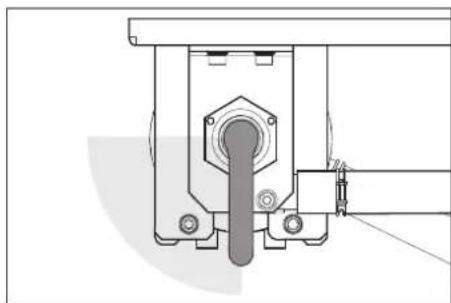
→ Turn the tension lever clockwise. The tension lever must rotate without difficulty into the area shown above. Otherwise, disassemble the tension lever and put it back in the correct position. → Secure the tension lever bearing with both screws. → Adjust the filter pre-tension.
Troubleshooting
⚠️ Danger
Danger of accident during work on the device. For all work
→ Remove the existing submersible pump.
Who is allowed to remove faults?
– Owner/concessionaire
www.kaercher.com/REACH
Warranty
1 Tensioning lever
2 Release lever
1 Nut
2 Tensioning lever
1 Mounting key
www.kaercher.com/REACH
Warranty
1 Fastening lever
2 Release lever
1 Nut
2 Fastening screw
3 Bearing screw for fastening
4 Flow coupling
5 Cover
6 Upper part
7 Filter cartridge
8 Filtrate tube
9 Threaded rod
10 Filament filter
11 Lower part
12 Lower bracket
13 Pin
1 Sliding block
→ Turn the locking lever and secure the filter pad by turning it slightly. → Place the lower part into the filament filter and push it all the way in. → Put the cover on the filament filter. → Place the filament filter on the lower console so that both rear pins are in the elongated holes of the console.
Warranty
1 Spray lance
Warranty
1 Locking lever
2 Locking lever
1 Handle
THANK YOU!
MERCI! DANKE! iGRACIAS!
Register your product and benefit from many advantages. Register your product and benefit from many advantages. Register your product and benefit from many advantages. Register your product and benefit from many advantages.
www.kaercher.com/welcome

Rate your product and tell us your opinion. Rate your product and tell us your opinion. Rate your product and tell us your opinion. Rate your product and tell us your opinion.

www.kaercher.com/dealersearch
Alfred Kärcher SE & Co. KG
Alfred-Kärcher-Str. 28-40
71364 Winnenden (Germany)
Tel.: +49 7195 14-0
Fax: +49 7195 14-2212


- CONTENTS
- ABOUT THIS OPERATIONS MANUAL
- TARGET GROUP FOR THESE INSTRUCTIONS
- DEFINITIONS
- FRESH WATER
- WASTE WATER
- PROCESSED WATER
- ENVIRONMENTAL PROTECTION
- NOTES ABOUT THE INGREDIENTS (REACH)
- WARRANTY
- SAFETY INSTRUCTIONS
- SYMBOLS USED IN THE OPERATION INSTRUCTION
- ⚠️DANGER
- ⚠ WARNING
- NOTICE
- GENERAL
- ⚠️ DANGER
- PROPER USE
- OPERATION
- OPERATING ELEMENTS
- ADJUST THE FILTER PRE-TENSION
- FILTER OPERATIONS
- NOTE
- BACKWASH
- PROCESSED WATER CIRCULATION
- FROST PROTECTION
- SHUTDOWN
- TRANSPORT
- CAUTION
- STORAGE
- FUNCTION
- FLOW PATTERN
- FUNCTIONAL DESCRIPTION
- FILTRATION
- FIRST FILTRATE/RINSE
- RECIRCULATION
- MAINTENANCE AND CARE
- MAINTENANCE INSTRUCTIONS
- WHO MAY PERFORM MAINTENANCE
- OPERATOR
- MAINTENANCE
- MAINTENANCE CONTRACT
- REPLACING FILTER INLAY
- NUT
- TROUBLESHOOTING
- ⚠ DANGER
- WHO MAY REMEDY FAULTS
- CUSTOMER SERVICE
- ACCESSORIES
- FILTER INLAY
- ATTACHMENT SET 'FRESH WATER SWITCHING
- INSTALLING THE UNIT (ONLY FOR EXPERTS)
- PREPARING THE INSTALLATION PLACE
- UNPACK THE EQUIPMENT
- WATER INSTALLATION
- SETTING THE FILTER PRELOAD
- CIRCULATION/RECIRCULATION
- TROUBLESHOOTING ASSISTANCE
- SAFETY NOTES
- SYMBOLS IN THE OPERATING INSTRUCTIONS
- FILTER PRE-TENSION ADJUSTMENT
- FILTER DRIVE
- WHO IS ALLOWED TO REMOVE FAULTS
- OWNER/CONCESSIONAIRE
- THANK YOU
- MERCI! DANKE! IGRACIAS
Brand : Kärcher
Model : WRP 1000 Classic
Category : Water filter