
SBSLI18 - Laboratory incubator STEINBERG - Free user manual and instructions
Find the device manual for free SBSLI18 STEINBERG in PDF.

| Product Type | Laboratory Incubator |
| Model | SBS-LI-18 |
| Brand | Steinberg |
| Power | 200 W |
| Voltage / Frequency | 230 V~ / 50 Hz |
| Dimensions (L x W x H) | 455 x 380 x 570 mm |
| Weight | 18.4 kg |
| Protection Class | I (grounding) |
| Adjustable Temperature Range | 0 °C to 300 °C (depending on controller) |
| Temperature Sensor | PT100 |
| Display | LED dual screen (PV and SV/TIME) |
| Temperature Control | PID with auto-tuning |
| Main Functions | Timer, over/under temperature alarm, screen lock, appointment function, deviation correction |
| Maintenance and Cleaning | Clean the chamber regularly; keep the device clean and dry; do not use flammable solvents |
| Safety | Grounding mandatory; do not cover vents; automatic shut-off in case of anomaly; protection against electric shock |
| Spare Parts and Repairability | Fuse, temperature sensor, heating element; repairs by authorized service only |
| General Information | User manual downloadable in PDF format; original manual in German |
Frequently Asked Questions - SBSLI18 STEINBERG
User questions about SBSLI18 STEINBERG
0 question about this device. Answer the ones you know or ask your own.
Ask a new question about this device
Download the instructions for your Laboratory incubator in PDF format for free! Find your manual SBSLI18 - STEINBERG and take your electronic device back in hand. On this page are published all the documents necessary for the use of your device. SBSLI18 by STEINBERG.
USER MANUAL SBSLI18 STEINBERG
This User Manual has been translated using machine translation. We have made every effort to ensure the translation is accurate, but please note that automated translations are not perfect and are not meant to replace human translators. The official version of the User Manual is in English. Any differences between the translated version and the original English are not legally binding. If you have any questions about the accuracy of the translation, please refer to the English version, which is the official reference.
Technical data
| Parameter description | Parameter value |
| Product name | Laboratory incubator |
| Model | SBS-LI-18 |
| Power [W] | 200 |
| Voltage [V] / Frequency [Hz] | 230~ / 50 |
| Dimensions (Width x Length x Height) [mm] | 455x380x570 |
| Weight [kg] | 18.4 |
| Protection class | | |
1. General overview
This manual is intended to assist you in safe and reliable use. The product is designed and manufactured strictly according to technical specifications using the latest technology and components, and maintaining the highest quality standards.
READ THE MANUAL CAREFULLY AND UNDERSTAND IT BEFORE USE.
To ensure long and reliable operation of the product, operate and maintain it correctly and strictly in compliance with this manual. The technical data and specifications in this manual are up-to-date. The manufacturer reserves the right to modifications for the purpose of quality improvement.
Explanation of symbols
| CE | The product meets the requirements of relevant safety standards. |
 | Read the manual before use. |
 | Recyclable product. |
 | CAUTION! or WARNING! or REMEMBER! indicates a specific instruction (general warning sign). |
 | CAUTION! Risk of electric shock! |

CAUTION! The product surface can reach high temperatures. Do not touch with bare hands while the product is in operation – risk of burns!

CAUTION! The figures in this manual are illustrative only and may vary in some details from the actual appearance of the product.
The original version of the manual is in German language. Other language versions are translations from German
2. Operating safety

CAUTION! Read all safety warnings and all instructions. Failure to follow the warnings and instructions may result in electric shock, fire and/or serious injury or death.
The term "appliance" or "product" in the warnings and instructions refers to the LABORATORY INCUBATOR.
2.1. Electrical safety
a) The appliance power cord plug must fit into the mains outlet. Do not modify the plug in any way. Original power cord plugs and matching mains outlets reduce the risk of electric shock.
b) Avoid touching earthed objects, like piping, radiators, heaters, and refrigerators. There is an increased risk of electric shock if your body is earthed and touching the appliance exposed to direct rain, a wet floor or while operating in a humid environment. If water penetrates into the appliance, there is an increased risk of damage to the appliance and electric shock.
c) Do not touch the appliance with wet or moist hands.
d) Do not use the power cord in any unintended way. Never use it to carry the appliance or to unplug it from the mains outlet. Keep the power cord away from sources of heat, oil, sharp edges or moving parts. Damaged or tangled cords increase the risk of electric shock.
e) If you cannot avoid using the appliance in a wet environment, use a residual current device (RCD) to connect the appliance to electrical mains. Using an RCD reduces the risk of electric shock.
f) Do not use the appliance if the power cord is damaged or shows evidence of wear. Have a damaged power cord replaced by a qualified electrician or the manufacturer's technical service.
g) To avoid electric shock, do not immerse the power cable, its plug or the appliance itself in water or other liquid. Do not use the appliance on wet surfaces.
2.2. Workplace safety
a) Keep the workplace tidy and well lit.
b) If in doubt as to whether the appliance is working, contact the manufacturer's technical service.
c) Repairs to the appliance may only be carried out by the manufacturer's service. Do not attempt to repair the product on your own!
d) In the event of ignition or a fire, use dry powder or CO2 extinguishers only to suppress the fire of the appliance if live with electrical voltage.
e) No children or unauthorised individuals shall be allowed at the workplace.
f) Use the appliance in a well-ventilated room.
g) In the event of a hazard to health or life, an emergency, or a failure, stop the appliance by operating the power switch!
h) Check the condition of the safety warning stickers regularly. Replace them if they are illegible.
i) Keep this manual for future reference. If the product is to be handed over to a third party, hand it over with this user manual.
j) Keep packaging components and small installation parts out of the reach of children.
k) Keep the appliance away from children and animals.
I) When operating this appliance together with other appliances, follow each of their user manuals.
2.3. Personal safety
a) Do not operate the product if you are tired, ill or under the influence of alcohol, drugs or medication which might significantly impair your ability to operate the product.
b) The product is not intended to be used by individuals (including children) with reduced mental, sensory or intellectual capacity or lack of experience and/or knowledge, unless they are supervised by an individual responsible for their safety or have been given instructions by the responsible individual on how to operate the product.
c) The appliance may only be operated by individuals who are physically fit, capable of handling the appliance and who have been adequately trained, have read this manual and have received training in health and safety.
d) Be careful and use common sense when operating the product. Even a brief moment of distraction during operation may lead to serious injury.
e) To prevent accidental operation, make sure the power switch is OFF before connecting the appliance to mains power.
f) The appliance is not a toy. Children must be supervised to ensure that they do not play with it.
2.4. Safe use of the product
a) Do not use the appliance if the power switch does not function properly (does not switch on or off).
b) Unplug the appliance from the mains before adjustment, cleaning or maintenance. This safety precaution reduces the risk of accidental operation.
c) Keep unused appliances out of the reach of children and anyone unfamiliar with the appliance or this manual. Appliances are dangerous in the hands of inexperienced users.
d) Keep the product in good working order.
e) Keep the product out of the reach of children.
f) The product shall be repaired and maintained by qualified personnel using original spare parts only. This will ensure safe operation of the product.
g) To ensure the designed operational integrity of the product, do not remove the factory-installed covers or loosen any bolts.
h) Clean the appliance regularly to prevent permanent deposits of dirt.
i) The appliance is not a toy. Cleaning and maintenance shall not be performed by children without adult supervision.
j) Never attempt to tamper with the appliance to change its parameters or structure.
k) Keep the appliance away from sources of fire and heat.
I) Do not cover the vents of the appliance!
m) Do not use flammable or explosive organic solvents while operating the appliance.
n) Do not place any volatile substances inside of the appliance in operation.
o) Do not apply mechanical pressure to the appliance or expose it to shock or fall.
p) Do not keep any objects on top of the appliance.
q) Do not move the appliance with any samples inside of it. If the appliance must be moved, first disconnect it from its power supply and use both hands to relocate the incubator while holding it level.
r) If any function fails, immediately stop the incubation process. Incorrect operating conditions may result in harmful action of the sample contents.

CAUTION!
Although the appliance has been designed to be safe and has been provided with adequate safeguards, and despite the use of additional safety measures, there is still a low, residual risk of accident or injury during its operation. Caution and common sense are advised when using the product.
3. Rules of use
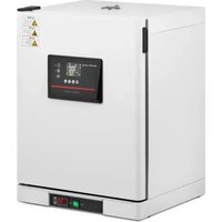
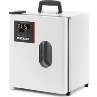
This product is intended for incubation and reproduction of living organisms in stable temperatures.
The user is responsible for any damage caused by non-intended use.
3.1. Preparations for operation
3.1.1 Working Conditions
• Voltage: 220V ±22V; Frequency: 50–60Hz ±1Hz
- Ambient Temperature: 5–40°C
• Relative Humidity: <90%
• Atmospheric Pressure: 80–106 KPa
• No intense vibrations or exposure to corrosive gases
- Keep away from direct sunlight and extreme heat or cold sources
3.1.2 Positioning the appliance
- Ensure the appliance is placed in a well-ventilated area with at least 20–30 cm of clearance on all sides.
• Always use the appliance on a stable, firm, clean, fire-resistant, and dry surface, away from children and individuals with reduced mental, sensory, or intellectual abilities.
• Position the appliance so that the mains plug is easily accessible at all times. - Verify that the mains power specifications match those indicated on the rating plate.
• Before first use, clean and dry the incubation chamber, then leave it to vent.
3.2. Operating the appliance
3.2.1 General procedures
1) Place the instrument on a flat surface or table.
2) Plug it into the appropriate power supply, ensuring that all grounding terminals of the power outlet are properly grounded.
3) Switch on the power; the power light will turn on.
4) Set the temperature according to the culture requirements. The temperature control device will display the current chamber temperature as it begins to heat.
5) Note: For pointer-type controllers, rotate the knob (refer to the digital controller's manual for digital instruments). Insert the culture after the temperature has stabilised for 30 minutes.
6) Once the experiment is complete, turn off the power, and the instrument will cease operation.

CAUTION!
- Ensure grounding is completed first, and select a grounding wire that is twice the thickness of the power cord.
- Keep the inner chamber clean at all times.
- Do not place any cultures directly under the chamber, and avoid placing cultures too close together to maintain proper air circulation.
3.2.2 Controller operation
Panel indication
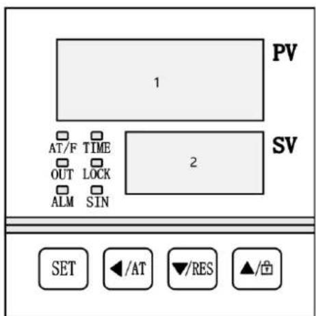
1- PV area.
2- SV/TIME area.
LED Controller Indicator Definitions
- "AT / F" Indicator: Lights up when the temperature is displayed in Fahrenheit. It flashes during the temperature auto-tuning process.
- "TIME" Indicator: Lights up when a timer is set. It flashes during the countdown or when the timer is in use.
- "OUT" Indicator: Lights up when the heater is active.
- "LOCK" Indicator: Lights up when the buttons are locked.
- "SIN" Indicator: This indicator is inactive.
- "ALM" Indicator: Lights up when there is an over-temperature alarm or if the temperature measurement is abnormal. It flashes during an under-temperature alarm. It remains off during normal operation.
3.2.3 Display Upon Power-On
- PC-D9000: When the controller is powered on, "P(K)-d9" appears in the PV area, and the version number is shown in the SV area. After approximately 3 seconds, the controller transitions to its normal operating state.
- PC-E9000: Initially, all displays are illuminated for about 3 seconds. Then, "P(K)-d9" is displayed in the PV area, and the version number appears in the SV area for 1 second. After that, the controller switches to its normal operating state.
3.2.4 Temperature and time setting
• Without Timing Function
1) In the main interface, press the SET button to enter the temperature setting mode. The PV area will display the prompt "SP," and the SV area will show the current temperature set value.
2) Use the SHIFT, DEC, and INC buttons to adjust the temperature setting.
3) Press the SET button again to return to the main interface, and the new settings will be saved automatically.
- With Timing Function
1) In the main interface, press the SET button to enter the temperature setting mode.
2) Press the SET button a second time to enter the time setting mode, indicated by the prompt "ST."
3) Press the SET button a third time to return to the main interface, and the new settings will be saved automatically.

NOTE
• If the time is set to zero, the controller will operate continuously.
- If the time is set to a value greater than zero, before the timer starts, the TIME area will display the set time in countdown mode and show zero in the forward timing mode.
4) During the timed operation, the TIME area will display the remaining time.
5) When the countdown finishes, the TIME area will display "End," and the buzzer will sound for the duration specified in EST (refer to "3.4. Parameter Table 1"), and the buzzer can be muted by pressing any button.
6) To restart the controller after the timer ends, press and hold the RST button for 3 seconds.
3.2.5 Appointment function
If an appointment time is set, the controller will start the appointment function. During the appointment timing process, the controller turns off the heating output, TIME area displays the appointment running time by countdown.
• PC-D9000: During the appointment timing process, A indicator flashes.
• PC-E9000: During the appointment timing process, TIM indicator flashes.
3.2.6 Abnormal temperature measurement alarm
If the PV area displays “---”, it indicates that the temperature sensor is faulty, the temperature is outside the measuring range, or the controller itself has an issue. In such cases, the controller will automatically cut off the heat output, the buzzer will sound continuously, and the ALM indicator will be on.
3.2.7 Temperature deviation alarm
If an over-temperature alarm occurs, the ALM indicator will be on, the heating output will be cut off, and the buzzer will sound. In the case of an under-temperature alarm, the ALM indicator will flash, and the buzzer will sound. If the deviation alarm is triggered due to a change in the temperature set value, the ALM indicator will be on, but the buzzer will remain silent.
3.2.8 Screen lock function
The controller offers three methods to lock the screen. Please refer to "3.4. Parameter Table 1" for details.
Method to unlock using a password: In the screen lock state, press the INC button. The PV area will display the password prompt "PA," and the SV area will show the password value. Enter the correct password and press the SET button to unlock the screen.
3.2.9 Mute function
When the buzzer sounds, press any button to mute it.
3.3. Auto-tuning of PID
If the temperature control performance is not optimal, the user can initiate the system's self-tuning program. Be aware that the self-tuning process may cause a large overshoot, so consider this before proceeding.
In the main interface, press and hold the AT button for 6 seconds to enter the self-tuning selection mode. The PV area will display the prompt "AT" and the SV area will show "0". Use the DEC or INC button to change the value to "1". Then, press the SET button to start the self-tuning program. The AT indicator will flash during the process. Once self-tuning is complete, the AT indicator will turn off and the PID parameters will be saved automatically. If you wish to stop the auto-tuning process, press and hold the AT button for another 6 seconds.

NOTE
- During system self-tuning, if an over-temperature alarm occurs, the ALM indicator will remain off, and the buzzer will not sound.
• The SET button is invalid while the system is self-tuning.
3.4. Internal parameters settings
In the main interface, press and hold the SET button for 3 seconds. The PV area will display the password prompt "Lc," and the SV area will show the password value. Adjust the password to the required value, then press the SET button again to enter the internal parameter setting mode. During this process, if you press and hold the SET button for another 3 seconds, the controller will return to the main interface, and the set value will be saved automatically.
Explanation
In the following table:
1) The temperature set point is referred to as SP, and the measured temperature is referred to as PV.
2) For a PT100 type controller, "M = 400.0°C". For a K-TC type controller, "M = 600.0°C".
Parameter Table 1
| Prompt | Name Function | description | (Set range)Factory value |
| Lc | Password. | When Lc is 3, user can enter this parameter table. | 0 |
| ALH | Over-temp alarm value | If “PV > SP + ALH”, the over temperature alarm will occur. | (0~100.0°C)20.0 |
| ALL | Under-temp alarm value | If “PV < SP - ALL”, the under-temperature alarm will occur.NOTE: If ALL is 0, this alarm function is invalid. | (0~100.0°C)0 |
| Pb | Deviation correction | It is used to correct the error in the temperature measurementPb = Actual temperature - PV | (-50.0~50.0°C)0 |
| PL | Slope correction. | It is usually used to correct the error in the high temperature measurement.PL = 1000 * (Actual temperature - PV) ÷ PV | (-999~999)0 |
| ndT | Timing mode | 0: No timing function1: Constant temperature timing2: Run timing | (0~2)1 |
| Tdn | Timing direction | 0: Positive timing1: Countdown | (0~1)0 |
| Hn | Timing unit | 0: Minute1: Hour | (0~1)0 |
| SPd | Constant-temp deviation | If “SP – SPd ≤ PV ≤ SP + SPd”,the controller enters the constant temperature state. | (0.1~50.0°C)0.5 |
| EST | Timing end buzzer time | When the timing is end, the Buzzer will beep for this time.NOTE: If EST is 9999, buzzer will beep continuously. | (0~9999s)60 |
| EH | Control after timing | 0: Cut off the heating output after timing1: Continue to control the temperature after timing | (0~1)0 |
| LF | Lock screen function | 0: No lock screen function1: With lock function, no need to unlock password.2: With lock function, need to unlock password. | (0~2)0 |
| LdT | Lock screen delay time | In the main interface state, the controller will lock the screen automatically if no button is pressed for this time.NOTE: If LdT is 600, this function is invalid. | (10~600s)30 |
| PAd | Unlock password | User must input this password to unlock. | (0~9999)1 |
| Add | Address The communication address | (1~32)1 | |
Parameter Table 2
| Prompt | Name Function | description | (Set range)Factory value |
| Lc | Password | When Lc is 6, user can enter this parameter table. | 0 |
| dP | Demarcation point | The demarcation point of low and high temperature PID control.“SP≤dP” is low temperature control.“SP > dP” is high temperature control. | (0~M°C)M |
| T | Control cycle | Heating PID control cycle | (1~30s)5 |
| P1 | Proportional band 1 | Proportional action adjustment at low-temp control. NOTE: “P1 = 0” is on-off control. | (0~300.0°C) 35.0 |
| I1 | Integration time 1 | Integral action adjustment at low-temp control. | (1~2000s) 300 |
| d1 | Differential time 1 | Differential action adjustment at low-temp control. | (0~1000s) 200 |
| nP1 | Power output 1 | The maximum power percentage of the heating output at low temperature control. | (0~100%) 100 |
| nH1 | Turn off deviation 1 | If “PV≥SP + nH1”, turn off the heating output at low-temp control. NOTE: Please use this parameter with caution! | (0~50.0°C) 50.0 |
| P2 | Proportional band 2 | Proportional action adjustment at high-temp. NOTE: “P2 = 0” is on-off control. | (0~300.0°C) 35.0 |
| I2 | Integration time 2 | Integral action adjustment at high-temp. | (1~2000s) 300 |
| d2 | Differential time 2 | Differential action adjustment at high-temp. | (0~1000s) 200 |
| nP2 | Power output 2 | The maximum power percentage of the heating output at high-temp. | (0~100%) 100 |
| nH2 | Turn off deviation 2 | If “PV≥SP + nH2”, turn off the heating output at high-temp. NOTE: Please use this parameter with caution! | (0~50.0°C) 50.0 |
Parameter table 3
| Prompt | Name Function | description | (Set range)Factory value |
| Lc | Password | when Lc is 27, user can enter this parameter table. | 0 |
| Fc | Temperature unit | 0: Centigrade; 1: Fahrenheit degreeNOTE: For K type controller, this function is invalid. | (0~1)0 |
Parameter table 4
| Prompt | Name Function | description | (Set range)Factory value |
| Lc | Password | when Lc is 81, user can enter this parameter table. | 0 |
| APT | Appointment time | Appointment time set value.NOTE: If APT is 0, this function is invalid. | (0~9999m)0 |
Parameter table 5
| Prompt | Name Function description | (Set range)Factory value | |
| Lc | Password | When Lc is 567, user can enter this parameter table. | 0 |
| rST | Factory reset | 0: Cancel to restore the factory value;1: Confirm to restore the factory value. | (0~1)0 |
| The indicator | Parameter Name | Description of the parameter function | (Range) Initial value |
| Lc | Password | Lc=9, parameter values can be viewed and modified | 0 |
| doT | Display decimal point | 0: No decimal point for temperature measurement and set value;1: The temperature measurement and the set value have 1 decimal point. | (0~1) 1 |
| oPn | The Door control Function | 0: No use; 1: Use | (0~1) 0 |
| SPL | Minimum. set value | The minimum value of the temperature setting. | (-50.0~20.0°C) 0 |
| SPH | Maximum set value | The maximum value of the temperature setting. | (20.0~M°C) 300.0 |
| EnL | Short of water alarming | 0 Disable1 enable | (0~1) 0 |
| ouT | Heating output mode | 0: normal state.1: The alarm relay output (normally opening point) is changed to heating output, and the original heating output is invalid. | (0~1) 0 |
| db | Nonsense region | The nonsense region of the temperature measurement. | (0~5.0) 0.0 |
| ndo | Switch output mode | 0: At the end of timing.1: Over-temperature alarm.2: Enter the constant temperature state | (0~2) 1 |
| ndA | Temperature alarm mode | 0: Only the temperature deviation over-temperature alarm.1: Temperature up and down deviation over-temperature alarm concurrently. | (0~1) 0 |
3.5. Troubleshooting
| Problems | Reason | Solution |
| No power | Plug is not plugged in or line breaks | Plug well or replace the plug |
| Fuse breaks | Replace the fuse | |
| Temperature does not increase | Temperature sensor breaks | Replace the sensor |
| Heater breaks | Replace the heater | |
| Inner wire joints loose or poor contact | Fasten wire joints |
3.6. Installation and Maintenance
• The surface (table) should be flat.
- Maintain a distance of 20-30 cm from the wall.
- Ensure good ventilation, with minimal dust and humidity not exceeding 85%.
- Keep the equipment clean and dry.
• Do not place any items on top of the unit.
3.7. Storage and Delivery
- Store the equipment in an environment with a temperature range of -20 to +40°C and a relative humidity of less than 80%.
- Avoid collisions and pressure during transportation.
3.8. Disposing of Used Devices
- Do not dispose of this device in municipal waste systems. Hand it over to an electric and electrical device recycling and collection point. Check the symbol on the product, instruction manual and packaging. The plastics used to construct the device can be recycled in accordance with their markings. By choosing to recycle you are making a significant contribution to the protection of our environment.
- Contact local authorities for information on your local recycling facility.

UWAGA! The figures in this manual are illustrative only and may vary in some details from the actual appearance of the product.
1- PV-gebied.
2- SV/TIME-gebied.
LED-controller-indicatordefinities
LÄS HANDBOKEN NOGGRANT OCH FÖRSTÄ DET INNAN ANVÄNDNING.
1- PV 30Ha.
2- Област SV/TIME.
Дефиниции на индикатора на LED контролера
For the disposal of the device please consider and act according to the national and local rules and regulations.
CONTACT
expondo Polska sp. z o.o. sp. k.


- General overview
- Operating safety
- Electrical safety
- Workplace safety
- Personal safety
- Safe use of the product
- CAUTION!
- Rules of use
- Preparations for operation
- Working Conditions
- Positioning the appliance
- Operating the appliance
- General procedures
- Controller operation
- LED Controller Indicator Definitions
- Display Upon Power-On
- Temperature and time setting
- NOTE
- Appointment function
- Abnormal temperature measurement alarm
- Temperature deviation alarm
- Screen lock function
- Mute function
- Auto-tuning of PID
- Internal parameters settings
- Explanation
- Troubleshooting
- Installation and Maintenance
- Storage and Delivery
- Disposing of Used Devices
- UWAGA! The figures in this manual are illustrative only and may vary in some details from the actual appearance of the product.
- LED-controller-indicatordefinities
- Дефиниции на индикатора на LED контролера
- CONTACT
Brand : STEINBERG
Model : SBSLI18
Category : Laboratory incubator