HDC Advanced - Pressure washer Kärcher - Free user manual and instructions
Find the device manual for free HDC Advanced Kärcher in PDF.
| Product type | Fixed high-pressure cleaner |
| Model | Kärcher HDC Advanced (HDC 60/10, HDC 90/10, HDC 120/10) |
| Power supply | 400 V three-phase, 50 Hz, power from 22 to 46.5 kW depending on model |
| Operating pressure | 10 MPa (100 bar) or 14 MPa (140 bar) depending on version |
| Flow rate | 6000 l/h (100 l/min) to 12000 l/h (200 l/min) depending on model |
| Maximum pressure (safety valve) | 14 MPa (140 bar) |
| Water supply | Minimum flow rate: 6000-12000 l/h depending on model, supply pressure 0.15-0.6 MPa (1.5-6 bar) |
| Max. supply temperature | 60 °C (standard version) or 85 °C (H version) |
| Dimensions (L × W × H) | 1168 × 800 × 1469 mm (HDC 60/10, 90/10) or 1881 mm (HDC 120/10) |
| Typical operating weight | From 450 kg (HDC 60/10) to 670 kg (HDC 120/10) |
| Protection type | IPX5 |
| Protection class | I |
| Display | LCD with display of pressure, operating hours and error codes |
| Safety devices | Dry-run protection, temperature sensor, motor circuit breaker, safety valve, discharge valve with flow meter, pressure sensor |
| Main functions | High-pressure cleaning, electronic regulation, automatic pump start/stop, adjustable timer |
| Care and maintenance | Daily check of hoses and handles, oil change every 500 hours, descaling if necessary |
| Compatible accessories | RM series detergents, high-pressure hose, washing brushes, lance |
| Warranty | According to local distributor conditions |
Frequently Asked Questions - HDC Advanced Kärcher
User questions about HDC Advanced Kärcher
0 question about this device. Answer the ones you know or ask your own.
Ask a new question about this device
Download the instructions for your Pressure washer in PDF format for free! Find your manual HDC Advanced - Kärcher and take your electronic device back in hand. On this page are published all the documents necessary for the use of your device. HDC Advanced by Kärcher.
USER MANUAL HDC Advanced Kärcher
71364 Winnenden (Germany)
Tel.: +49 7195 14-0
Fax: +49 7195 14-2212
Winnenden, 2021/02/01
Garantie
Please read and comply with these original instructions prior to the initial operation of your appliance and store them for
later use or subsequent owners.
Before first start-up it is definitely necessary to read the safety indications Nr. 5.956-309.0!
-In case of transport damage inform vendor immediately.
Contents
| Environmental protection EN 1 | |
| Danger or hazard levels EN 1 | |
| Symbols on the machine EN 1 | |
| Safety instructions EN 1 | |
| Proper use EN 1 | |
| Function EN 2 | |
| Safety Devices EN 3 | |
| Device elements EN 4 | |
| Start up EN 5 | |
| Operation EN 5 | |
| Shutdown | EN 5 |
| Technical specifications EN 6 | |
| Transport | EN 8 |
| Storage EN 8 | |
| Care and maintenance | EN 8 |
| Troubleshooting | EN 9 |
| Accessories | EN 10 |
| Installing the plant | EN 11 |
| EU Declaration of Conformity | EN 11 |
| Warranty | EN 11 |
| Customer Service | EN 12 |
Environmental protection
| The packaging material can be recycled. Please do not throw the packaging material into household waste; please send it for recycling. | |
| Old appliances contain valuable materials that can be recycled; these should be sen for recycling. Batteries, oil, and similar substances must not enter the environ-ment. Please dispose of your old appli-ances using appropriate collection sys-tems. |
Please do not release engine oil, fuel oil, diesel and petrol into the environment Protect the ground and dispose of used oil in an environmentally-clean manner.
Kärcher detergents are easy-to-dispose. This means that the functioning of an oil separator is not hampered Please find a list of recommended detergents in the chapter "Accessories".
Notes about the ingredients (REACH)
You will find current information about the ingredients at:
www.kaercher.com/REACH
Danger or hazard levels
ADANGER
Pointer to immediate danger, which leads to severe injuries or death.
△WARNING
Pointer to a possibly dangerous situation, which can lead to severe injuries or death.
CAUTION
Pointer to a possibly dangerous situation, which can lead to minor injuries.
ATTENTION
Pointer to a possibly dangerous situation, which can lead to property damage.
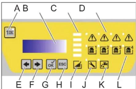
Symbols on the machine
Risk of burns! Beware of hot components.
Safety instructions
- Please follow the national rules and regulations for fluid spray jets of the respective country.
- Please follow the national rules and regulations for accident prevention of the respective country. Fluid spray jets must be tested regularly and the results of these tests must be documented in writing.
- Please follow the safety instructions which are attached to the used detergents (normally on the packing label).
Work-stations
The work station is located at the display. Depending on the plant installation, other work-stations are located at the accessories (spraying units) that are connected to the feeder points.
Personal safety gear

Wear ear plugs to protect your ears against hearing loss while cleaning parts that produce high sound levels.
- Wear protective clothing and safety goggles to protect against splash back containing water or dirt.
Proper use
- This system transports water to the down-the-line high pressure units with high pressure. This unit is permanently installed in a dry room. There must be a water and a power connection present according to the details provided in the technical specifications. The temperature at the installation site should not exceed 40^ . The high pressure water is distributed through a fixed network of pipes.
Only clean water may be used as high pressure medium. Impurities will lead to increased wear and tear or formation of deposits in the appliance. - Above 15^ , measures for hardness reduction may become necessary.
- The use of recycled water must be prearranged with Kärcher in advance.
DANGER
Risk of injury! Follow the respective safety regulations when operating at gas stations or other dangerous areas.
Please do not let mineral oil contaminated waste water reach soil, water or the sewage system. Perform engine cleaning and bottom cleaning therefore only on specified places with an oil trap.
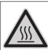
Function
Flow pattern
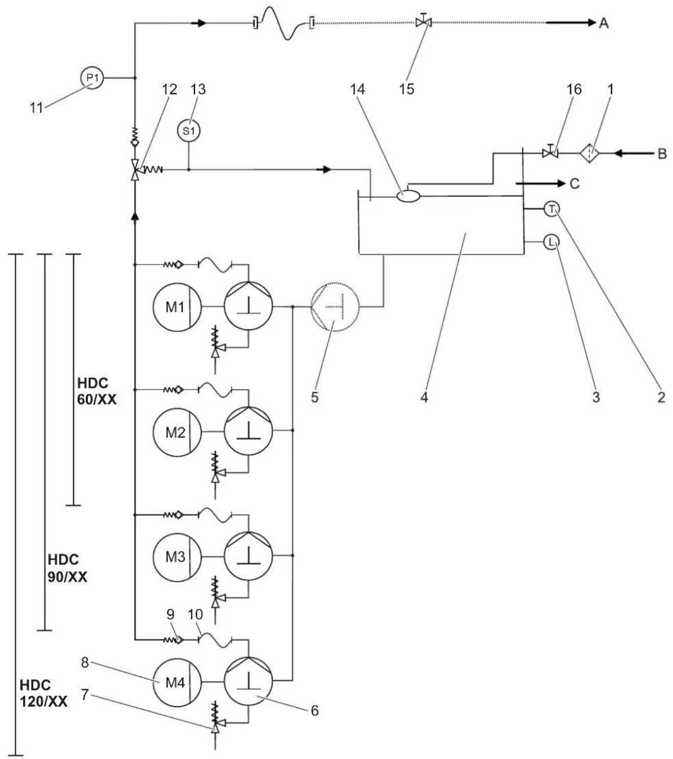
1 Dirt catcher (at the site)
2 Temperature sensor
3 Water shortage safeguard
4 Float tank
5 Advance pressure pump
(0)
6 Crankshaft pump
7 Safety valve
8 Electro motor
9 Backflow valve
10 High pressure hose
11 Pressure sensor for high pressure
12 Overflow valve
13 Flowmeter
14 Swimmer valve
15 Locking tap (onsite)
16 Locking tap (onsite)
A Pipeline/high pressure outlet
B Water inlet
C Overflow
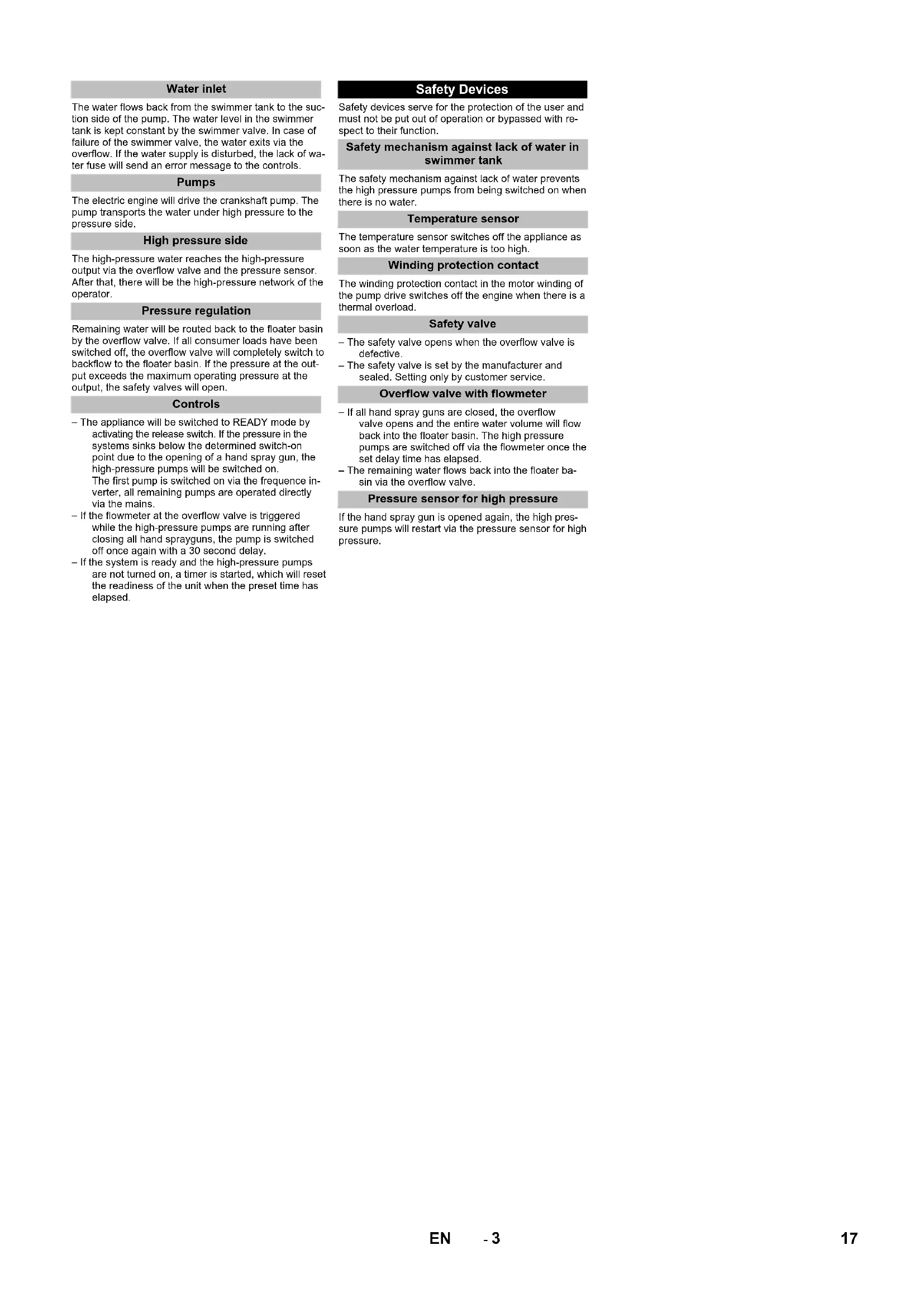
Water inlet
The water flows back from the swimmer tank to the suction side of the pump. The water level in the swimmer tank is kept constant by the swimmer valve. In case of failure of the swimmer valve, the water exits via the overflow. If the water supply is disturbed, the lack of water fuse will send an error message to the controls.
Pumps
The electric engine will drive the crankshaft pump. The pump transports the water under high pressure to the pressure side.
High pressure side
The high-pressure water reaches the high-pressure output via the overflow valve and the pressure sensor. After that, there will be the high-pressure network of the operator.
Pressure regulation
Remaining water will be routed back to the floater basin by the overflow valve. If all consumer loads have been switched off, the overflow valve will completely switch to backflow to the floater basin. If the pressure at the output exceeds the maximum operating pressure at the output, the safety valves will open.
Controls
- The appliance will be switched to READY mode by activating the release switch. If the pressure in the systems sinks below the determined switch-on point due to the opening of a hand spray gun, the high-pressure pumps will be switched on. The first pump is switched on via the frequence inverter, all remaining pumps are operated directly via the mains.
- If the flowmeter at the overflow valve is triggered while the high-pressure pumps are running after closing all hand sprayguns, the pump is switched off once again with a 30 second delay.
- If the system is ready and the high-pressure pumps are not turned on, a timer is started, which will reset the readiness of the unit when the preset time has elapsed.
Safety Devices
Safety devices serve for the protection of the user and must not be put out of operation or bypassed with respect to their function.
Safety mechanism against lack of water in swimmer tank
The safety mechanism against lack of water prevents the high pressure pumps from being switched on when there is no water.
Temperature sensor
The temperature sensor switches off the appliance as soon as the water temperature is too high.
Winding protection contact
The winding protection contact in the motor winding of the pump drive switches off the engine when there is a thermal overload.
Safety valve
- The safety valve opens when the overflow valve is defective.
- The safety valve is set by the manufacturer and sealed. Setting only by customer service.
Overflow valve with flowmeter
- If all hand spray guns are closed, the overflow valve opens and the entire water volume will flow back into the floater basin. The high pressure pumps are switched off via the flowmeter once the set delay time has elapsed.
- The remaining water flows back into the floater basin via the overflow valve.
Pressure sensor for high pressure
If the hand spray gun is opened again, the high pressure pumps will restart via the pressure sensor for high pressure.
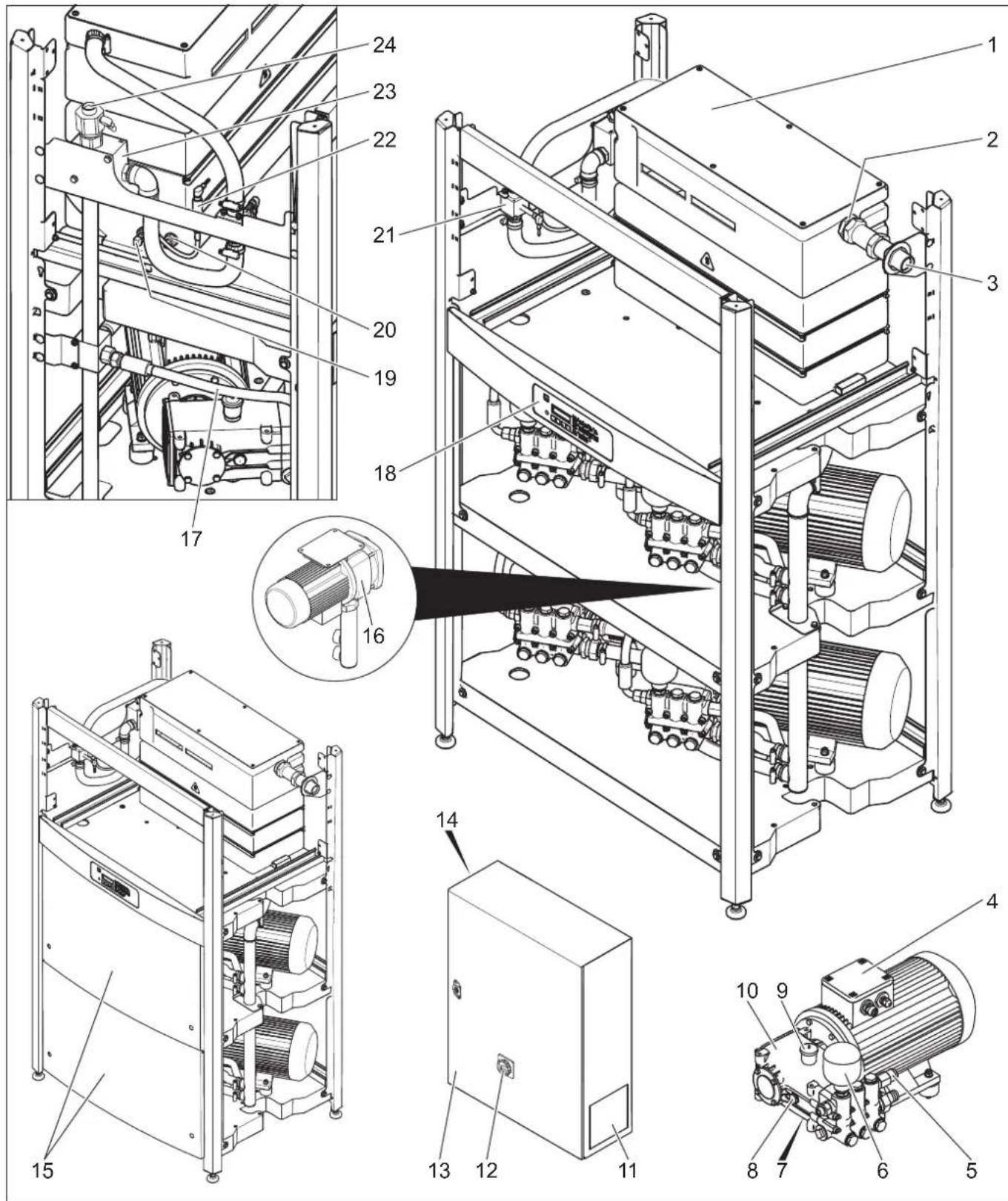
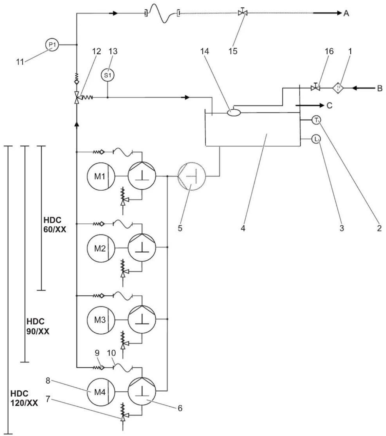
1 Float tank
2 Swimmer valve
3 Water connection
4. Electro motor
5 Safety valve
6 Pressure tank
7 Oil drain screw
8 Oil level indicator
9 Oil tank
10 High-pressure pump
11 Filter ventilator
12 Main switch
13 Control board
14 Exit filter
15 Front panel sheet metal
16 Advance pressure pump
(Option)
17 High pressure hose
18 Display
19 Temperature sensor
20 Water shortage safeguard
21 Flowmeter
22 Pressure sensor for high pressure
23 Overflow valve
24 High pressure connection
Start up
△DANGER
Risk of injury! Device, tubes, high pressure hose and connections must be in faultless condition. If they are not in a perfect state then the appliance must not be used.
Operation
Safety instructions
The operator must use the appliance correctly. When working with the appliance, he must consider the local conditions and pay due care and attention to other persons, in particular children, who are nearby. Never leave the appliance unattended when it is in operation.
DANGER
Danger of scalding by hot water! Do not direct the water jet on persons or animals.
- Risk of burns on account of hot surfaces! Do not touch uninsulated pipes and hoses when hot water operations are on. Hold the jet pipe only at the handles.
Risk of poisoning or itching on account of detergent! Follow the given instructions for using detergents. Store detergents safely and protect them against access by unauthorised persons.
△DANGER
Risk to life on account of electric shock! Do not direct the water jet on the following equipment:
- Electrical appliances and plants,
the unit itself,
- all electricity-carrying parts in the working area.
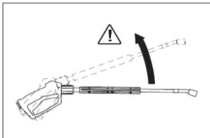
There is a recoil pressure arising from the water jet that comes out from the spray pipe. The angular spray pipe brings about an upward force.
△DANGER
- Risk of injury! The recoil pressure of the spray pipe can throw you off-balance. You may fall. The spray jet can fly off and cause damage to persons. Search a secure place to stand and hold the gun firmly. Never hold on tightly to the lever of the hand spray gun.
- The jet must not be directed at other persons or directed by the user at him/herself to clean clothing or footwear.
Risk of injury from parts flying off! Flying-off fragments or objects can injure people or animals. Never direct the water jet on fragile or loose objects.
Risk of accident on account of damage! Clean tyres and valves from a minimum distance of 30 cm.
DANGER
Danger from substances that are harmful to health! Do not spray the following materials as they swirl up substances that are harmful to health:
Materials containing asbestos,
Materials that could contain substances harmful to health.
△DANGER
Risk of injury on account of the emanating water jet that could be hot! Only original Kaercher high pressure hoses are optimally suited for the plant. No guarantee can be given if you use any other hoses.
Detergents can prove to be a health hazard! If any detergents are added, the water let out of the plant is not of potable quality.
Risk of hearing impairment while working on noise-making parts! If so, wear ear plugs.
Machine vibrations
△WARNING
Long hours of using the appliance can cause circulation problems in the hands on account of vibrations.
It is not possible to specify a generally valid operation time, since this depends on several factors:
- Proneness to blood circulation deficiencies (cold, numb fingers).
Low ambient temperature. Wear warm gloves to protect hands.
-A firm grip impedes blood circulation. - Continuous operation is worse than an operation interrupted by pauses.
In case of regular, long-term operation of the device and in case of repeated occurrence of the symptoms (e.g. cold, numb fingers) please consult a physician.
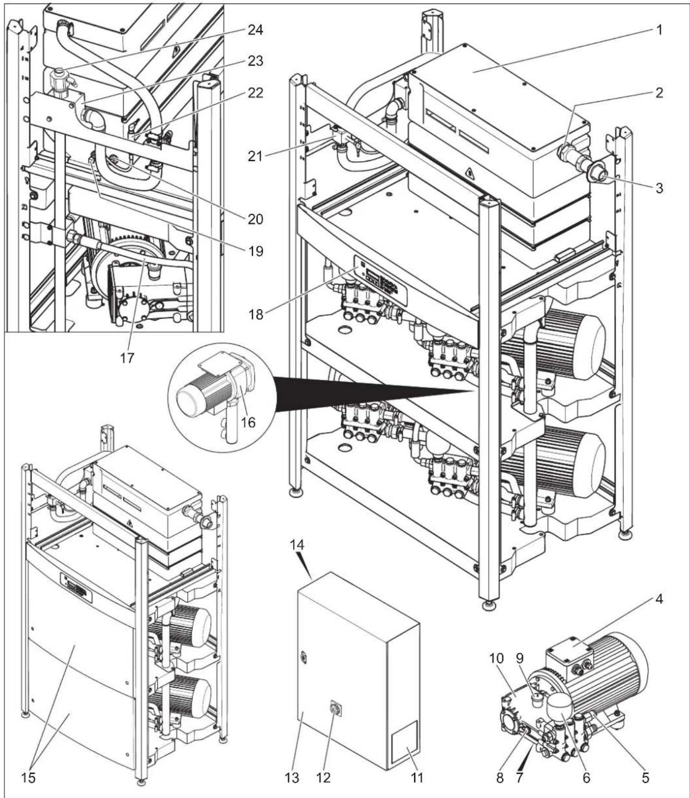
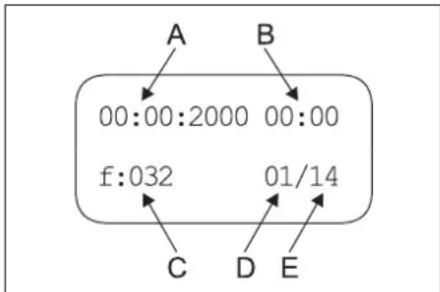
Display
Note: The text is shown in English.
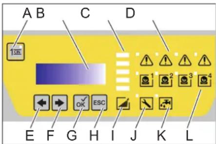
A Unlocking button
B LCD display
C Bar graph (approx. 20% of the nominal pressure per field)
D Fault message pumps 1-4
E Change value (-) or move cursor to the left
F Change value (+) or move cursor to the right
G Acknowledgment button (OK)
H Cancel (ESC)
I System pressure
J Collective fault
K Water shortage
L The respective pump is switched on.
- When the system is ready to operate, the current operating hours of the high pressure pumps are shown alternating with the operating pressure.
- When errors are triggered, these are shown on the display as well (see "Help with errors").
Making the plant ready for operations
△DANGER
Risk of injury on account of the emanating water jet that could be hot!
△DANGER
Check the high pressure hose for damage before every use. Please arrange for the immediate replacement of a damaged high pressure hose.
Check high pressure hose, pipe connections, fittings and water jet for damage every time before use.
Check hose coupling to ensure that it sits firmly and is leak-proof.
Switch-off in case of emergency
Turn the main switch to position "0".
Shut off water supply.
Activate trigger gun until device is pressure-less.
Turning on the Appliance
Open the water supply.
Turn the main switch to position "1".
Press the unlocking key.
Perform the cleaning operation
Note: If the cleaning break exceeds the set delay time (min. 30 seconds), the appliance will stop. At the same time, a adjustable operation readiness period will be started. Within this operation readiness period, the appliance will automatically switch on because of the drop in pressure when the hand spray gun is opened.
Getting the system ready for operations
Press the unlocking key
Turn off the appliance
Turn the main switch to position "0".
Shut off water supply.
Activate trigger gun until device is pressure-less.
Secure the hand spray gun using the safety catch so that it doesn't open accidentally.
Shutdown
If the appliance is not to be used for a longer period or if it is not possible to install it in a frost-free environment, you must take the following measures (see chapter "Maintenance and care", section "Anti-freeze protection"):
Drain water.
Flush device with anti-freeze agent.
Switch off the main switch and secure it.
Technical specifications
| HDC 60/10 HDC 90/10 HDC 120/10 | HDC 60/10 H HDC 90/10 H HDC 120/10 | |||||
| Performance data | ||||||
| Working pressure MPa (bar) 10 (100) 10 (100) 10 (100) 10 (100) | ||||||
| Max. excess operating pressure (safety valve) | MPa (bar) 14 (140) 14 (140) 14 (140) 14 (140) 14 (140) 14 (140) 14 (140) 14 (140) 14 (140) 14 (140) 14 (140) 14 (140) 14 (140) 150 (150) 12000 (200) 6000 (100) 9000 (150) 12000 (200) | |||||
| Flow rate l/h (l/min) 6000 (100) 9000 (150) 12000 (200) 6000 (100) 9000 (150) 12000 (200) | ||||||
| Water connection | ||||||
| Min. feed volume | l/h (l/min) | 6000 (100) | 9000 (150) | 12000 (200) | 6000 (100) | 9000 (150) |
| Feed pressure (min.) | MPa (bar) | 0,15 (1,5) | 0,15 (1,5) | 0,2 (2,0) | 0,15 (1,5) | 0,15 (1,5) |
| Max. feed pressure | MPa (bar) | 0,6 (6) | 0,6 (6) | 0,6 (6) | 0,6 (6) | 0,6 (6) |
| Max. feed temperature | °C | 60 | 60 | 60 | 85 | 85 |
| Electrical connection | ||||||
| Current type | -- | 3~ | 3~ | 3~ | 3~ | 3~ |
| Frequency | Hz | 50 | 50 | 50 | 50 | 50 |
| Voltage | V | 400 | 400 | 400 | 400 | 400 |
| Connected load | kW | 22 | 34 | 45 | 23,5 | 46,5 |
| Electrical protection (slow) | A | 50 | 80 | 100 | 50 | 80 |
| Type of protection | -- | IPX5 | IPX5 | IPX5 | IPX5 | IPX5 |
| Protective class | -- | I | I | I | I | I |
| Power supply | mm² | 4x 16 | 4x 35 | 4x 35 | 4x 16 | 4x 35 |
| Dimensions and weights | ||||||
| Length | mm | 1168 | 1168 | 1168 | 1168 | 1168 |
| Width | mm | 800 | 800 | 800 | 800 | 800 |
| Height | mm | 1469 | 1469 | 1881 | 1881 | 1881 |
| Typical operating weight | kg | 450,1 | 545,1 | 650,1 | 470,1 | 565,1 |
| Values determined as per EN 60335-2-79 | ||||||
| Noise emission | ||||||
| Sound pressure level LpA | dB(A) | 74 | 76 | 76 | 74 | 76 |
| Uncertainty KpA | dB(A) | 1 | 1 | 1 | 1 | 1 |
| Hand-arm vibration value | ||||||
| Hand spray gun | m/s² | 3,63 | 3,63 | 3,63 | 3,63 | 3,63 |
| Spray lance | m/s² | 7,52 | 7,52 | 7,52 | 7,52 | 7,52 |
| Uncertainty K | m/s² | 1,0 | 1,0 | 1,0 | 1,0 | 1,0 |
Exception according to Regulation (EU) 2019/1781 Annex I Section 2 (12): a)
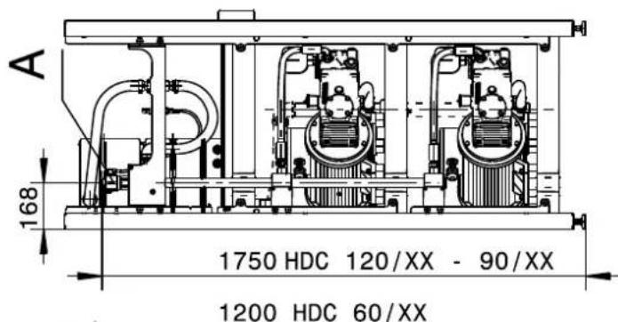
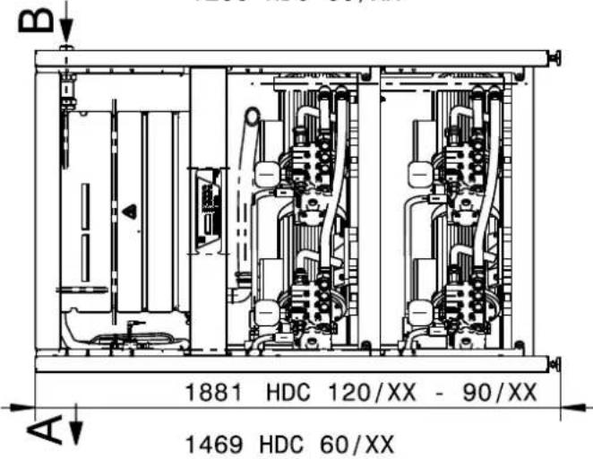
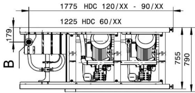

Illustration HDC 120/XX without metal panels
A High pressure connection
B Water connection
C Minimum wall distance
D Space requirements for switch cabinet
| F | S | u | r | f | a | c |
| H | H | e | i | g | h | t |
e
Transport
CAUTION
Risk of injury and damage! Observe the weight of the appliance when you transport it.
When transporting in vehicles, secure the appliance according to the guidelines from slipping and tipping over.
Storage
CAUTION
Risk of injury and damage! Note the weight of the appliance in case of storage.
Care and maintenance
DANGER
Risk of injury! The main switch is to be switched off while carrying out any repairs or maintenance jobs.
Maintenance schedule
| Time Activity Assembly affected Performance of whom | |||
| daily Check hand-spray | gun | Hand spray gun | Check whether the hand-spray gun closes tightly without any leaks. Check the protection mechanism against accidental switching. Replace defective hand-spray guns. |
| Check high pressure hoses | Outlets, hoses towards working machine | Check hoses to see if there are damages. Replace defect hos- es immediately. Danger of accident! | |
| weekly or after 40 operat- ing hours | Check the unit for leaks | Entire plant Check pumps, overflow valve and pipe system for leaks. Inform Customer Service if there is oil below the pump or if there is a leakage of more than 3 drops of water per minute. Keep the leakage borings clear. | Operator/Cus- tomer service |
| Check oil level | Oil level indicator on the pump | If the oil is milky, it needs to be replaced. | |
| Check oil level | Oil level indicator on the pump | Check oil level of the pump. Refill oil if required (Order no. 6.288-016) | |
| monthly or after 200 oper- ating hours | Check pump | High-pressure pump | Check the pump for leaks. If the leakage is more than 3 drops per minute, call Customer Service. |
| Check water scarcity fuse | Swimmer switch in the swimmer tank | Press the swimmer of the low water fuse down for about 5 sec- onds and control the error indicator on the control board. Re- move deposits if necessary. | |
| Test swimmer valve | Float tank | The water level must be 40 mm below the overflow. No water must exit while the swimmer valve is closed. Adjustment - see service manual. | |
| Check overpump time. | Controls | Close consumer loads (e.g. hand spray guns). The pump must switch off after the afterrun period. | |
| Test automatic start | Pressure sensor | The pump stands still as there is no water transfer. Open the hand spray gun. If the pressure in the high-pressure cycle falls below the switchpoint, the pump must switch on. | |
| Tighten hose clips | All hose clips | Tighten the hose clips using a torque wrench. Tightening torque up to a diameter of 28 mm = 2Nm, from 29 mm = 6 Nm. | |
| half-yearly or after 500 op- erating hours | Oil change | High-pressure pump | Drain off oil. Fill in 1 l of fresh oil (order no. 6.288-016.0). Check the oil level at the oil level indicator. |
| half-yearly or after 1000 operating hours | Check the appliance for calcium deposits | entire water system | Improper functioning of valves or pumps can be an indication of calcium deposits. If necessary decalcify. |
| Tighten clamps | Control board | Tighten all clamps for components in the main circuit. | |
| annual | Safety check | Entire plant | Safety check according to the guidelines for fluid spraying equipment. |
| Depending on ambient conditions | Check the filter mats of the ventilator | Control board | Check the filter mats of the ventilator for contamination and clean if necessary. Replace with new filter mats after cleaning them 10 times. |
Maintenance contract
You can enter into a maintenance contract with the concerned Kaercher Sales Office for the machine.
Frost protection
The machine should be stored in frost-free rooms. In case there is frosting risk, for e.g. if the machine is installed in open areas, then the machine must first be emptied and flushed using an anti-freezing agent. Drain water
Screw off water supply hose and high pressure hose.
Operate device for max. 1 minute until the pump and conduits are empty.
Flush device with anti-freeze agent
Note: Observe handling instructions of the anti-freeze agent manufacturer.
Fill in normal anti-frost agents in the swimmer tank right until the top.
Place the collection trough under the high pressure exit.
Switch on the appliance and let it run until the safety mechanism against lack of water in swimmer tank gets activated and the machine is switched off.
A certain corrosion protection is achieved with this as well.
Troubleshooting
△DANGER
Risk of injury! The main switch is to be switched off with all repair work.
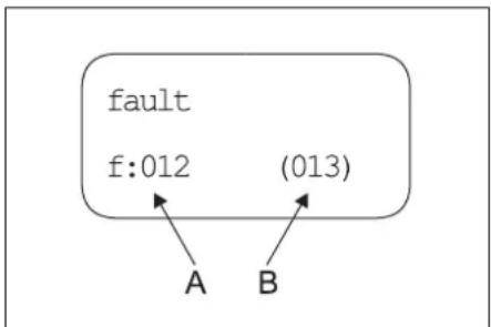
A Error number
B Number of currently present errors
| Error num-ber | Error description Error type |
| 01 Control voltage is missing 2 | |
| 02 Display, no communication 2 | |
| 10 Motor protection switch high pressure pump 1 | 1 |
| 11 Motor protection switch high pressure pump 2 | 1 |
| 12 Motor protection switch high pressure pump 3 | 1 |
| 13 Motor protection switch high pressure pump 4 | 1 |
| 14 Motor protection switch of the frequency inverter or frequency inverter not ready | 2 |
| 18 Winding protection contact high pressure pump 1 | 1 |
| 19 Winding | protection contact high pressure pump 2 | 1 |
| 20 Winding | protection contact high pressure pump 3 | 1 |
| 21 Winding | protection contact high pressure pump 4 | 1 |
| 26 Motor protection switch ad- vance pressure pump | 2 | |
| 30 Switch "On" constantly occu- pied (control input) | 2 | |
| 31 Switch "On" constantly occu- pied (display) | 2 | |
| 32 Switch "Off" constantly occu- pied (control input) | 2 | |
| 40 Water shortridge 2 | ||
| 41 Water temperatur is too high 2 | ||
| 42 Leakage switch-off 1 (e.g. hose burst) | 2 | |
| 43 Leakage switch-off 2 (minor leakage) | 2 | |
| 45 Pressure too high (> 300 bar) 2 | ||
| 46 Flowmeter issues incorrect signal | 2 | |
| 47 Overflow valve adjusted in- correctly | 2 | |
| 48 HDC type set incorrectly 2 | ||
| 49 Flowmeter does not emit sig- nal | 2 | |
| 50 Pressure sensor for high pressure does not transmit signal | 2 | |
| 52 Temperature sensor does not transmit signal | 2 | |
- Error type 1: Emergency operation of the system with remaining high pressure pumps.
- Error type 2: The operating readiness of the system is switched off and the high pressure pumps are shut off.
If one of the above errors occurs, the appliance can be restarted after the error has been corrected by activating the release switch.
Note: The 40 most recently occurred errors are saved with the respective date and time and can be shown on the display.

A Date of error event
B Time of error event
C Error number
D List location of error
E Number of saved errors
| Fault Possible cause Remedy | of whom | ||
| Appliance is not running | There is no voltage in the machine. | Check electrical mains. | Electrician |
| Motor protection switch for the control has been triggered. | Check motor protection switch. | Customer Service | |
| Pump starts during the stand-by period and not when the hand spray gun is opened. | Pressure sensor for high pressure or cable to pressure sensor defective. | Replace pressure sensor or cable. | Customer Service |
| Full pressure does not build up in the appliance | Flushed the nozzle. | Replace the nozzle. | Operator |
| Suction site pipe leaking. | Check screw fittings and hoses. | Operator | |
| Safety valve is leaky. | Check the setting; install new washers, if required. | Customer Service | |
| Overflow valve is leaking or set too low. | Check valve parts; replace damaged parts; clean the dirt. | Customer Service | |
| Valve in the pump defective, high-pressure solenoid valve does not close. | Replace defective components. | Customer Service | |
| High pressure pump is knocking; ma-nometer is swaying wildly | Pump is sucking air. | Check suction system and remove leaks. | Operator |
| Valve plate or valve spring is defective. | Replace defective components. | Customer Service | |
| Advance pump calcified or defective. | Check advance pump. | Operator | |
| Overflow valve opens and closes contin-ously during 0 takeover | Leakage in the high-pressure pipeline system or hand spray gun leaking. | Locate and seal leakage. | Operator |
| Backflow valve or control piston seal leaking in overflow valve. | Repair the overflow valve. | Customer Service | |
| Error code 01 is displayed | Control board defective, green LEDs are not blinking. | Check control board, replace if necessary. | Customer Service |
| Error number 10, 11, 12, 13 is displayed | Overflow protection switch of the respective high pressure pump has been triggered. | Rectify cause for over-loading. | Customer Service |
| Error code 14 is displayed | Motor protection switch has been triggered or frequency inverter not ready. | Rectify cause for over-loading. | Customer Service |
| Error number 18, 19, 20, 21 is displayed | Thermal sensor of the respective motor has been triggered. | Rectify cause for over-loading. | Customer Service |
| Error code 26 is displayed | Overflow protection switch of the advance pressure pump has been triggered. | Rectify cause for over-loading. | Customer Service |
| Error code 40 is displayed | The water shortage safeguard in the swimmer tank has got activated. | Remove the water shortage. | Operator |
| Swimmer valve is jammed. | Check swimmer valve for free movement. | Operator | |
| Error code 41 is displayed | The temperature sensor in the swimmer tank has been activated. | Reduce water infeed temperature. | Operator |
| Error code 42 is displayed | Leakage in the high-pressure pipeline sys-tem. | Locate and seal leakage. | Operator |
| Too many consumer loads open at the same time. | Close some consumer loads. Operator | ||
| Pressure sensor for high pressure defective. | Replace pressure sensor. | Customer Service | |
| Fault | Possible cause | Remedy | of whom |
| Error code 43 is displayed Leakage in the | high-pressure pipeline sys-tem. | Locate and seal leakage. Operator | |
| Pressure sensor for high pressure defective. | Replace pressure sensor. Customer Service | ||
| Error code 45 is displayed Pressure too | high (>300 bar). Incorrect nozzle inserted. Insert correct nozzle. Operator | ||
| Pressure sensor for high pressure defective. | Replace pressure sensor or cable. Customer Service | ||
| Error code 46 is displayed | Flowmeter issues signal >50 l/min flow, althought no pump is running. | Check flowmeter, replace if required. Customer Service | |
| Error number 47 is displayed (although the nominal pressure was not reached, more than 400 litres of water flow back into the float container over a period of more than 25 seconds) | Overflow valve adjusted incorrectly. | Adjust the overflow valve correctly. | Customer Service |
| Overflow valve is defective. Replace overflow | valve. Customer Service | ||
| Nominal pressure entered incorrectly in the display menu. | Enter nominal pressure correctly. Customer Service | ||
| Pressure sensor for high pressure defective. | Replace pressure sensor or cable. Customer Service | ||
| Flowmeter defective. Replace flow meter. | Customer Service | ||
| Error code 48 is displayed | HDC type incorrectly set in the display menu. | Set HDC type to Advanced. | Customer Service |
| Error code 49 is displayed | Flowmeter does not emit signal. | Check flowmeter, replace if required. | Customer Service |
| Error code 50 is displayed Pressure sensor | or for high pressure does not transmit signal. | Check pressure sensor and cable, replace if necessary. Check board A5. | Customer Service |
| Error code 52 is displayed Temperature | sensor in the float container does not transmit signal. | Check temperature sensor and cable, replace if necessary. Check board A5. | Customer Service |
Accessories
Detergent
Detergents simplify the cleaning tasks. The table gives a selection of detergents. Please read the instructions on the packaging carefully before working with any detergents.
| Area of application | Target group | Detergent | Kärcher description | Dosaging in high pres-sure |
| Foaming | Food industry/disassembly facilities | Disinfection cleaning | RM 732 | 1-3% |
| Disinfectant | RM 735 | 0,75-7% | ||
| Foam disinfecting detergent, alkali-based | RM 734 | 2-5% | ||
| Beverage facilities/wine cellars | Foam detergent, alkali-base | RM 58 ASF | 1-2% | |
| Foam cleaner, acidic | RM 59 ASF | 1-2% | ||
| Foam disinfecting detergent, alkali-based | RM 734 | 2-5% | ||
| Community | Exterior foam cleaner, neutral | RM 57 | 1-2% | |
| Disinfecting cleaner, inside | RM 732 | 1-3% | ||
| Agriculture | Disinfection cleaning | RM 732 | 1-3% | |
| Disinfectant | RM 735 | 0,75-7% | ||
| High-pressure cleaning | Beverage facilities/wine cellars | Universal cleaner | RM 55 | 0,5-8% |
| Foam disinfecting detergent, alkali-based | RM 734 | 2-5% | ||
| Community | Active cleanser, alkali-based RM 81 | 1-5% | ||
| Agriculture | Active cleanser, alkali-based RM 31 | 1-5% | ||
| Active cleanser, alkali-based RM 81 | 1-5% | |||
| Ship equipment | Active cleanser, alkali-based RM 81 | 1-5% | ||
| Automotive/lorry workshop | Active cleaner, alkali-based (engine/parts) | RM 31 | 1-5% | |
| Active cleaner, alkali-based (vehicle, top and bottom wash) | RM 81 | 1-5% | ||
| Floor cleaning | Food industry/disassembly facilities | Intensive basic cleaner | RM 750 | 1-5% |
| Floor basic cleaner | RM 69 | 0,5-1% | ||
| Beverage facilities/wine cellars, community | Intensive basic cleaner | RM 750 | 1-5% | |
| Floor basic cleaner | RM 69 | 0,5-1% | ||
| Automotive/lorry workshop | Intensive basic cleaner | RM 750 | 1-5% | |
| Floor basic cleaner | RM 69 | 0,5-1% | ||
| Ship equipment | Intensive basic cleaner | RM 750 | 1-5% | |
| Floor basic cleaner | RM 69 | 0,5-1% | ||
| Washing brush | Community | Exterior active cleanser, alkali-based | RM 81 | 1-5% |
| Universal cleaner | RM 55 | 0,5-8% | ||
| Automotive/lorry workshop | Active cleaner, alkali-based (vehicle, top and bottom wash) | RM 81 | 1-5% | |
| Ship equipment | Exterior active cleanser, alkali-based | RM 81 | 1-5% |
Installing the plant

Only for authorised technicians!
Assembly
ATTENTION
Always keep the installation site of the system well ventilated to protect the machine against over-heating.
The appliance should not be directly attached to the network of water and high pressure pipes. It is mandatory to install the connecting hoses.
- A shut-off tap must be installed between the main water supply and the connecting hose.
Installing the high pressure connections
For installation, please follow the specifications of the VDMA sheet 24416 "High pressure cleaners; fixed high pressure cleaning systems; concepts, requirements, installation, testing" (the German version can be procured from Beuth Verlag, Cologne, www.beuth.de).
- The pressure loss in the pipe connections must lie below 1.5MPa .
- The completed pipe connections must be checked using 32 MPa.
- The insulation of the pipes must be resistant to temperatures until 100^ .
Water supply
ATTENTION
Risk of damage to the plant if water supply is not of suitable quality.
Note: Impurities in the inlet water can damage the unit. Karcher recommends a water filter with a mesh width of < 80 m .
Quality requirements for tap water:
| pH value 6,5...9,5 | |
| electrical conductivity \( < {2000\mu }\mathrm{S}/ \) cm | |
| removable materials \( < 0,5\mathrm{{mg}}/\mathrm{l} \) * | |
| filterable materials (grain size be- low 0.025 mm) | < 20 mg/l |
| Hydrocarbons < 20 mg/l | |
| Chloride < 300 mg/l | |
| Calcium < 85 mg/l ** | |
| Total hardness \( < {15}^{ \circ }\mathrm{{dH}} \) ** | |
| Iron \( < 0,5\mathrm{{mg}}/\mathrm{l} \) | |
| Manganese \( < 0,{05}\mathrm{{mg}}/\mathrm{l} \) | |
| Copper \( < 0,{02}\mathrm{{mg}}/\mathrm{l} \) | |
| free of bad odours | |
- Test volume 1litre, Settling time 30 minutes
** decalcification measures are necessary if the values are higher
The water inlet is to be connected to the main water supply using a water hose. - The water supply must have a minimum output of 6,000 l/h for HDC 60/10, 9,000 l/h for HDC 90/10, 12,000 l/h for HDC 120/10 at minimum 0.15 MPa (HDC 60/10, HDC 90/10) or at minimum 0.2 MPa (HDC 120/10).
Appliances without prepressure pump: The water temperature must lie below 60^ .
-Machines with prepressure pump: The water temperature must lie below 85^
Electrical connection
Note: Operating procedures create short term power sinkings. During unfavorable net conditions other devices might be disturbed.
- For connection values, see technical data and type plate.
The electrical connections must be done by an electrician according to IEC 60364-1.
Current-carrying parts, cables and appliances in the working area must be installed in a defectless state and must be protected against water sprays.
HDC 60/10 (H): This device complies with IEC 61000-3-12 under the condition that the short-circuit power Ssc at the connecting point between the customer system and the public mains is greater than or equal to 10400 (11000) kVA. It is within the responsibility of the electrician or the user of the unit to ensure - if necessary after consulting the mains operating company - that the device is only connected to a point of an Ssc value greater than or equal to 10400 (11000) kVA.
△DANGER
To avoid accidents due to electrical faults we recommend the use of sockets with a line-side current-limiting circuit breaker (max. 30 mA nominal tripping current).
EU Declaration of Conformity
We hereby declare that the machine described below complies with the relevant basic safety and health requirements of the EU Directives, both in its basic design and construction as well as in the version put into circulation by us. This declaration shall cease to be valid if the machine is modified without our prior approval.
Product: High pressure cleaner
Type: 2.509-xxx
Relevant EU Directives
2006/42/EC (+2009/127/EC)
2009/125/EC
2011/65/EU
2014/30/EU
Applied harmonized standards
EN IEC 63000:2018
EN 55014-1:2017 + A11:2020
EN 55014-2: 2015
EN 60335-1
EN 60335-2-79
EN 61000-3-2: 2014
EN 61000-3-3:2013
EN 61000-3-12: 2011
EN 61000-6-2: 2005
EN 61000-6-4:2007
EN 62233: 2008
Applied regulations
(EU) 2019/1781
5.957-926
The signatories act on behalf of and with of the authority of the company management.

Chairman of the Board of Management
S. Reiser
Director Regulatory Affairs & Certification
Documentation supervisor:
S. Reiser
Alfred Karcher SE & Co. KG
71364 Winnenden (Germany)
Tel.: +49 7195 14-0
Fax: +49 7195 14-2212
Winnenden, 2021/02/01
Warranty
The warranty terms published by our competent sales company are applicable in each country. We will repair potential failures of the appliance within the warranty period free of charge, provided that such failure is caused by faulty material or defects in fabrication.
| Customer Service | ||
| Plant type: Manufact. no.: Start-up on: | ||
| Testing done on:Findings:Signature | ||
| Testing done on:Findings:Signature | ||
| Testing done on:Findings:Signature | ||
| Testing done on:Findings:Signature | ||

2006/42/CE(+2009/127/CE)
2009/125/CE
2011/65/UE
2014/30/UE
Chairman of the Board of Management

S. Reiser
Director Regulatory Affairs & Certification
Responsible de la documentation : S. Reiser
Alfred Karcher SE & Co. KG
Alfred-Karcher-StraBe 28-40
71364 Winnenden (Germany)
Tel.: +49 7195 14-0
Fax: +49 7195 14-2212
Winnenden, 2021/02/01
Garantie
www.kaercher.com/REACH
Livelli di pericolo
PERICOLO
2006/42/CE (+2009/127/CE)
2009/125/CE
2011/65/UE
2014/30/UE
Chairman of the Board of Management

S. Reiser
Director Regulatory Affairs & Certification
71364 Winnenden (Germany)
Tel.: +49 7195 14-0
Fax: +49 7195 14-2212
Winnenden, 2021/02/01
Garanzia
H.Jenner

Chairman of the Board of Management
S. Reiser
Director Regulatory Affairs & Certification
71364 Winnenden (Germany)
Tel.: +49 7195 14-0
Fax: +49 7195 14-2212
Winnenden, 2021/02/01
Garantie
2006/42/CE(+2009/127/CE)
2009/125/EG
2011/65/UE
2014/30/UE
Chairman of the Board of Management

S. Reiser
Director Regulatory Affairs & Certification
Responsible de documentacion:
S. Reiser
Alfred Karcher SE & Co. KG
71364 Winnenden (Germany)
Tel.: +49 7195 14-0
Fax: +49 7195 14-2212
Winnenden, 2021/02/01
Garantia
www.kaercher.com/REACH
Niveis de perigo
PERIGO
2006/42/CE (+2009/127/CE)
2009/125/CE
2011/65/UE
2014/30/UE

Chairman of the Board of Management

Director Regulatory Affairs & Certification
71364 Winnenden (Germany)
Tel.: +49 7195 14-0
Fax: +49 7195 14-2212
Winnenden, 2021/02/01
Garantia
www.kaercher.com/REACH
Faregrader
△FARE
Henvisiter en umidelbar fare, der fereit alvortige kvaesteler efteri tldeden
ADVARSEL
2006/42/EF (+2009/127/EF)
2009/125/EF
2011/65/EU
2014/30/EU

Chairman of the Board of Management

S. Reiser
Director Regulatory Affairs & Certification
71364 Winnenden (Germany)
Tel.: +49 7195 14-0
Fax: +49 7195 14-2212
Winnenden, 2021/02/01
Garanti
www.kaercher.com/REACH
Risikotrinn
△FARE
2006/42/EF(+2009/127/EF)
2009/125/EU
2011/65/EU
2014/30/EU

Chairman of the Board of Management

S. Reiser
Director Regulatory Affairs & Certification
71364 Winnenden (Germany)
Tel.: +49 7195 14-0
Fax: +49 7195 14-2212
Winnenden, 2021/02/01
Garanti
www.kaercher.com/REACH
Risknivaer
E4BA
Symboler pa aggregate
Forbranningsrisk! Varning for mycket varma enheter.

Chairman of the Board of Management

S. Reiser
Director Regulatory Affairs & Certification
Dokumentationsbefullmaktigad:
S. Reiser
Alfred Karcher SE & Co. KG
71364 Winnenden (Germany)
Tel.: +49 7195 14-0
Fax: +49 7195 14-2212
Winnenden, 2021/02/01
Garanti
www.kaercher.com/REACH

Chairman of the Board of Management
S. Reiser
Director Regulatory Affairs & Certification
Winnenden, 2021/02/01
Takuu
www.kaercher.com/REACH
Aiaβαθuiσn Kivδuωv
KINADYNO2
YrOeileic Yia aea eTnaiouev KIOUVO, o OTIOc μTPOeIvaexiωuVETeiaooapo ngavaoio TpauaTiaio.
△NPOEIAOIOIHEN
YnObeiEic yia ma duynntika emkivouv n kataaon, n oroiu mptoe va exei wouveia oobapo havaoipo traupaiano.
△NPOEOXH
YIOEiN yia iua evEXOeVWC EIKIVouvN kAOTAON, n OTOIA IPOeI VA oBNyNEI e LE appO rpaunioo.
NPOOxH
YnOBeiŋ yia maovniKaEtnivovn karaTaon, n oTolma mTopei va exi wS ouvTeia ulikesζmies.
Σμβολα σην Σσκεύ
Kivouc ykaumaw! Pnoeio- roian yia kaura doikra otoixia.
Ytobeiieic aqpaaleias
-△WATE TPOOONIOTIC EKAOTOE TPOIDAYPAPEC TNC ΘEVIKNVSVOOEOIAOACETIKAEITIGKETIOUMTCE uovpW.
-△wotte TPOOONOTIC EKAOTTE DIATAEIEC TcEviKnV voooteia oxetika me nTv atotpotn atuxnPaTuov Oauokuec ktoTmUv Upvu ToTpeTVA uToBaaovTai OE Aeyyo oTe takiia diaotmuata KaIa atiotaAeouata Tou Eeyxou 0a TpeTe va KATAypaovTai KA vuaolaoovTai.
- AβaTe TuaTic UoOBeIEc aαpαλeIac Tou auvoδεuovTu atoppuattvakTu pnoioutoie (Ka-ta KaVOba TnTg EtKtα OuaKeuaOiaC).
OeicEpyaia
H 8eON epyaTlac BpIoketai otNv oOvN. IepaTePw OeEiC epyaTlac bpaKovTa avaloyuTs diataeNtS movadac stn pOoBtana unXavnJATA (biataeic ykaaou) taOnla ouVbEvoiTa me Ta onmuia buqatwoon.
PpOoWtIKOs PpOoTaeutIKOs EosTAloos

Kata tov KaBapiao TuHaTov uynAnxntiKs EVAaOns, opate wtoaTtides yia tv Ptolnny AkoouTikuv Blauov.
- Ia va npoataeueBeite ano tic mtaiaiec tou vepeou n ato touc purouoc, opatne npoataeutikn otai Ka yuaia.
Chairman of the Board of Management

Director Regulatory Affairs & Certification
YTeuBuvoc EyypaWv Teknpiwns S.Reiser
Alfred Karcher SE & Co. KG
71364 Winnenden (Germany)
Tel.: +49 7195 14-0
Fax: +49 7195 14-2212
Winnenden, 2021/02/01
Eyyunon
www.kaercher.com/REACH
Tehlike kademeleri
TEHLIKE

Chairman of the Board of Management

S. Reiser
Director Regulatory Affairs & Certification
Dokumantasyon sorumlusu:
S. Reiser
Alfred Karcher SE & Co. KG
Alfred-Karcher-Straße 28-40
71364 Winnenden (Germany)
Tel.: +49 7195 14-0
Fax: +49 7195 14-2212
Winnenden, 2021/02/01
Garanti
www.kaercher.com/REACH
CTeneHb onaCHOctn
ONACHOCTb
Ykaaahue omhocumnbHenocepceemHo 2p03nue onaohcmo, Komopar npuobodm K mjaenbymyeebam UNU K cmepmu.
△PENEYNPEXDEHNE
Yka3aHue omHocumelbHO 803MOXHO NOMEHuaJIbHO onaOHcU cumauu, KOMOPAR MOKEM npueecmu K mJekbIM yeeyam unu K cmepu.
OCTOPOXHO
YkaaHue na nomenauNbHO onaChyu cmyaHIO, KOMopar moKem npueecm u K nonyeHuo nekuxmpaM.
BHIMAHNE
Yka3aHue omhOcumeIbHO 803MOKHOUI NOMeHUuaJIbHO onaCHou cumyaauu, Komopar MoKem noBneMbmepuaJIbHIy uep6.
CIMBOJbHa np6ope
Onachocmb oxoaa! PnpdynpkeJdene o eopnux y3nax.
Yka3aHnno TExHnke 6e3onacHOCTN
-Heo6xoJHMoCo6nHOaBbCoOTBcTcByOuHne HaIOHOHaBHbIe 3aKHOHaTeBbIbe HOpMbNo pa6oTe C JMDKOCtBbIMn CTpyJBHMy yCTaOBKaBMn.
-Heo6xOdMoC6bNHOaTb COOTBCTBYKUHMe HAIOHbIbHe 3A KOHOaTeBbIe HOpMbI NO TEXHNKe 6EoNaChOcTn. Heo6xOdMo peryrnpHO npOBepRbPabOt yKnXoCTbIX CTpyHbIX YCTAHOBOK INpe3yIbTaT npOBepK OΦOPMnTb B NcMbEmHOMBVDte.
-CnEnyet co6n4aTb yka3AHHNo texHnke 6e3- onaHcOCTN, pInnaeraMble K nCNOB3yeMbIM MOIOUM CpeCTBaM (Ka npabNIO, npnbEeHHHe Ha 3TNKETKe yNAKOBN).
Paboyne MecTa
Pa6oee MeTo OTo6paKeHo Ha DnCnPe. Dpyne pa 6oOe MeTae, B3aBcIMcOCTN oKCHpTyKmY cTahOB- K, HaxoTcR Bo3e yCTpoCTB DOJOnHInTeNbHO 6opbyOBOHaHn (paCbNteNe), KOtOpBe NoDcoEHHK 3aapBoUHbIM ToykAM.
CpeCTBA INHINBHyaIbHo3aunTbI

PnOuCTKe YactE,ycnNBAHOx3ByK,Heo6XoHMO Hocntb COOTBeTcBtBuOuIe CpeDCTBa 3aOuTbOpraHOB CnyxAJnpreTOBpaueHn IN NOBpeDeHn.
Iinaumbyompanemaouxcn6bla0e8oodyuap3u cneyo hocum coomeemcmyouyaoumnyo oexoyu auzumhbo yauzumhbo ouk.
NcNoJIb3OBAHHe NO Ha3HaYeHNIO
JaHHaYcTaHOBKa NOD BbICOKIM DaJIbEHMeN MoIaET BOy K NOcOeINHeHHbIM YcTOpOBCTBAM YHCTKo. OHa DOnJHKb 6b8 JtckEeK TCMOHTIPOBAH BA CyXOM NOMUeHN. TaKke DoJIKHO 6b8 TpeJyCMOTPeHO NOpKIOUeHN K BOdONpOBoBOy IN CTOHNYKToKA corNaCHO yka3AHmR BpaDene "TexMHeCKne DAHNbIE". Ha Meete 3KcIIpyaTauN cYCTAOHBOKn TEMnepaTypa BO3dyxA He DoJNKHa npeBbIaHT 40°C.PacnPpeJeHMe HBoN DNO BbICOKIM DaJIbEHMeN OcyueCTBJIETC Yepe3 XeKTKO CMOHTPiPOBaHHO CETb TpyoIPoBOoDB.
B KaheCTBe cpeBb BlicOKo RaDaBHeHr MoKHO HcNoJIb3OaBt ToIbKO UcHTyBOyD.3aPra3HeHrNpINBoI R NpExeBpeMeHHOMHy I3HOcy YcTpoCTBa INOTOnkHeHnB H EBM OCAJaK.
- Pπn dH 60lee 15° Moketntnepe6oBaTbCp npHHaTne MeP no CHINKENHO XeCTKOIN.
-Пименевные Вобл NOВТОРНО МСОЛБЗОВАЙ
ДоЖнб 6ытп рпсдарпгьнбcorriacobaoC
Kärcher.
ONACHOCTb
Onachocmb nonyeHnmpaam!Ppu ucnnoB3o8aHuHa aem03anaepoOyHbIX cmaHuaXUn e dpyaux onaChbIx 3oHax cobIpaTaumeemcmyouque npaeuna mexHku6e3onachocmu.
IpoKaIyIcTa, He donyckaIte nonaHaHncreTCHbIX BOD, codepkauxm HmepaHbIe MaCna, B NOBy, BO-oeMbl INN KaHn3aCuIO. IocToMy MoKy MToPOB nDHHu aBtOMaHIN pTOBko B PnCNOco6NeHHbIX drr 3rTO rMeCTax C MacNoynobITEJeM.
1PraeynoBntel(ha yctaHOBke)
2 DaTcHk TemnepaTypb
3 CnTeMa npdoXpaHeHr O TcYrTbHr BOBd
4NonnabKobKaMepa
5 Hacoc npeBapntbHoro daBneHnna (Onu)
6KoJIeHbAJIbHbI Haoc
7 PpeoXpaHnteBhN KnaH
8 ΘηκτροΜΟΤρ
9 O6paTHbI KnaHaH
10UNaHr BbICOKOraDaBneHn
11 DaTnK DaBHeHnI DnBbICOKoDabHeHn
12 Pepenyckho Knaan
13 PacxoDomep
14NonnaBkoBbKnlaan
15 3anophbl KnanaH (Ha ycTaHOBke)
16 3anophbn KlnanaH (Ha yctaHOBke)
A Tpy6oPbOoB/8bIXoB BcOKoro DaJIeHn
B Podaa BODbI
C PepenonHne
Poaay BoBbI
Boa BixoJNT 36 KaC nONnABKOM K BCacBbAoueien CTOPOHE HACOCA.C NOMOUBO NNONABKOBO KNAHANBA Boake c NOIaBKM OyepKINAEcT NocToHHN ypoBeHB BOi. PnO tKtAE NNNABKOBO KNAHANA BOa BblNBaeTcYepe3 nepeynckHOe TBPcTne. PnH apyuHenn BOOCha6XeHN BIdaetc Coo6uHHe 06 OOW6ke CNCTeMbY npabHEnr npedoxpAHENr OT CYCTBNI BOi.
Hacocbi
3NEKPTOMOT PnBODNT B DeIeCTBNE KOHeHBaIbHbI Hacoc.HacocNoaet BOy NOB BILcOKIM DabJIeHMe CO CTOPoHb HArTeTAHN.
CTOPOHA BbICOKO DAABNEHIN
Boda noi BbICOKM DabNeHem nonaAet uepe3 nepeynckHO KnanaHn dATNk DabNEHnK B bXOy DbCOKoR aDabHeHn. 3aTe m CneIyET cTb BbcOKoro DabHeHnnotpe6nteJr.
PerynpoBaHne daBHeHn
OctabwacB Oda BepHcTc OT nepenyckHoro Knaana Ka6ky c nonnabKOM. EcnN BCE NOTpeBnTeN oTKnOHe Hb, MoKHO nOncBoTbNopeKIOuHTb nepenyckHoi Knaanah HaOBpatnhNnotOK K6ky c nonnabKOM. EcnDaBnEHHe Ha BixOJe He CMOTpHa NcNOJb3ObaHne nepenyckHOro Knaana npeBbIaeaT MaKcMmAbHoe paBOoee DaBnEHHe, TO OKpbBaIaOTcPpeDoxpaHnTeNbHbKnaanHb.
Блok ураловая.
-Пи NOmOuIN KHOIN DE6NOKINPOBKN yCTpoIcTB PnINBOIDNTC B TOROBHOCTK KcNpnyatauIN. Пи NOHIXeHN DABNEHIN B CNTeMe NytEM OTKpbTIN PuyHrO NIOCTONeta-pacblNJInTeN B YCTaHOBNEN HO TQKe NEpeKJIIOUeHIN, HACoBb BILCOKOrO DAB ENHIN BKNIQUAOTCR. NepBb HAcOC BKNIOVAeTCR Yepe3 AcTOThb Npeo6P30aOBatEn, DpyrHe HAcocb pa5oTaIOT npM OTO 3NeKtPOCen.
-Ecnn BbKIOHHTb pacxoOOpMep Ha nepeynckHom Knaane npa pabotaOeH Hacoce BbCOKo DABENHn Nocne 3akpITB NCex pyhBx NCTOnTeOB paacnNTeJIe, HAcCOb CHOb BA KbIKHOATOJ NOcne 3adepKKN, 3NaHeHne KOtopoI perynpnyetc.
- Ecnn yctahOBkra roToBa Ka p6oTe a hacocb BbicoKOrO DaBHeHn He p6oTaIO To CpaBaTbBAe TAI-Mep KOTOpBn IO NCTeHEny UcTaHOBnHrO BpeMeHN BO3BpaAaET rTOBHOCTb YcTAHOBKn Ka p6oTe B NCXODHoe NOIooHne.
3aunthbyeyctpoictBa
3aunHtBHe pncnocO6bHeNcnyKatIg 3aunTbI NObn3oBaTeN I He OdoNkHb YbIOdNtCb n3 cTPO Hn paOToT b OBxOcbONXfHyKnL.
CnTeMa npdoxpanenr O TcTCTBn BObl,6akCNNONJIaBkOM
CnTeMa npEdoXpaEHnO NT OTCYCTBn BObl npEoTbPaaet BKNIOeHne HAcOCOB BICOKO DaBNEHn PnH NEOCTaKe BObl.
DaTchK TemnepaTpybI
Дачн TemnepaTybl OTKHouaet annapat npn DoCTNKeHIM CmUkOM BbICOKOf TempeApTybl BObl.
3aHTbI 06MOToHbI KOHTaKT
3aunHbI OMBOTOHbIKOHTAKT B OMBOTKE MOTOPa nPBOda HACoCA OTKNHOaET MOTOp npTepeMHecko neperpy3ke.
PpeOxpaHHTenbHbI Knaan
-Преторхантеловй Кланан OTKpbIbAeTcB Cnly-уае Нсправно nepenyckHoro Кланана.
-Ппебхангтелькланн Habtpoehи onnombipoban ha 3aboe. Habtpoika ocyuiectbnaetcTOnbko cepnschon cnykboi.
Ipeynckno knanac pacxodomepom
- Ecnn 3aKpbTb BCE pyHbIe NtCTOnTeBpacnblnten, OTKpoETc nepeNcKHO Knahan H 06uee KOJIHeCTBO BODB BepHEcT B NoPbnA BoKyIO KaMepy. PaXoDOpem OTKnHuaET HacoCb IbCoKOrO DaBHeHn NO IcTeHEni BbIcTaBNeHHOro BpeMeHN 3aJePkXn.
-IOCTOARHHe KOJIueCTBO BOIbI nepeTeKaET Ha3aB B6akC nonnabKom Uepe3 nepenynckHO KnanaH.
DaTnK BbICOKOra daBneHna
PnIOBTOPHOMOTKpBTHyPUHORIOIHCNTOENA-pacblJIENTeHaCocbI BcICOKO DaBHeNCHOBaIPOROHOITXJIKOCbYpe3DATMKBbICOKO DaBHeN.
1NonnabKOBaKaMepa
2NonnabKOBbI KnaHaH
3POnKNoHHe BOOCha6KeHH
4 ΘneKtpoMOTop
5 PpeOxpaHHTeBHyknaHa
6 P e c n B e p
7 B H T C n y c k a
8Yka3aTeIb yPoBHa MacnA
9Ma c n H bI 6aK
10 Hacoc BbICOKO TaBneHn
11BeHTnIaTOpCΦnJIbTpOM
12IaBbIyBbIKIOUaTeJIb
13 PacpeJeHnTeBHybI uKaΦ
14 BbIyckHOH pIbTp
15 Pepedn nnct 6wnBkn
16 Hacoc npedBapntbHoro daBneHHa
(Onu)
17UnaHrBbICOKOrDaBJeHn
18 Dnne
19 DaTHNK TemnepaTpybl
20 CnTeMa npedeoxpaeHnO T OTCyTCTBn BOBbl
21 BacxDomepa
22 DaTnK daBHeHnI dNra BbICOKOro daBHeHnI
23 Pepenynckno knanah
24 CoeHHeHbICOKoDaBnHeH
Hauano pa60tby
ONACHOCTb
OnachocmbmpaBmblPpupob,pnoobdy,wnhae bico Kooa daenHua u noKnovHeu dnonKbHu haoDumc8 e6bynpuehOM cocmoHuu.Ecu cocmOHaue He reBaemc ucnpaebHM,moycmpoucmeo uonnb3oeamb HeB3a.
UnpaBneHne
Yka3aHnno TeXnke 6e3oNaChocTu
Nonb3oaeamnb donjhen ucnnonb3oabmb npubop e coomemcmeu c hazhauheuem. Oh donjhen yumblabmb mecHbte ocoBENHOCMu u opaamb bHMaHue npu paObe c npubopom Ha dpyux nu, haxoRauxxrc noBnucmU.
3anpeuaemc oemaemb paobmaouu npub6e3 npucmopma.
ONACHOCTb
- ONaChocmb obapaeBAnH aOpyeH oOoiHa He naepaemmb uana h naoei nuu KusombHx.
Onacnoctb okooe o oopue 3meHmbl ycmahoe
ku! npa pabome c oopueo bdoou He npukacaiimec K
Heu3olnpoeaHHbIM mpyoepoeodam u unnaam.
CmpuyHyto mpy6ky ydepkuaBm mbonka 3a aauky
pykoarnku. - Onachocmb ompaebHeu nU xumueckko 0xOkaa MOOUUMU cpecmeamU! PtunrHbE BO EHMauhe yka3aHua, npueeodHeBn Ha ynakoe MOUeze cpeCmEA CoXPaHmB MOUeae cpeCMeo a Mece, HeoCMyTNHom dnn HeynnonHOOMeHbIX NNU.
△ONACHOCTb
Onachocmbnapozenha mokom!He hanaepnume CMPyo ebo hy cnedeyouoe ycmpocemae?
3neKmpueeckue npubopby u ycmahoeku,
Ha co6cmeeHHo 3my ycmhaHOky,
Ha 8ce mokoeedyue demaru pa6oue3oHe.

IV3-3a CTPyn BObl, BblXoJaIe H3 CTPynHO Tpy6kn, BO3HnKaET Cnla OTDaH. IV3-3a TORO, VTO CTPynHAp Tpy6ka pacnoJIOKeHa NoD yrIOM, Cnla DeIeCTByeT BBePx.
△ONACHOCTb
Onacnocmb nonyuhenma pmaem! Cuna omdauchmpyuhou mpybko mozem npayummb aawa paahoeecue. Bly mozem ynaem. Cmpyihara mpyka mozem ebimembe u mpaemupoaeam okpykauxx niodeu. Bbyepume ydo6hnyo nozuiu odnpabombu kpenko ydepxkuaume pyhoi nuonem-pacbninumeb. Hukoeda he zaknuueaumepbhae ypuhoo nucmonema-pacbnunumea
He papeewaemcmaekhe hainpaenmbcmpyoo bHa npdyux unu c6b dnyucmku oedkobu unu obyu.
Oraochomb nonyuhenmuabmy omomemaohux qacmei! Omemaouue obnmou unpeoMembmoympaumpuoeambnoei unu kooemhIX.He harnpaenmbcmpy oobha bbooeecaun HesakpenneHbne peoMemb.
OnaChocmb aapuu bcndcmeue noepxdeHn! UuHb u kanaHb oucumtb c MuHumaBbIM paccmosHuem 30 cm.
ONACHOCTb
Onachocmb, bbl3eaHnna onachbIMu dnn 3doopo6ba eeecemaMuHe paccnmb ncdyoouue mamepuanbl, mank kae eo3dyx moym nohmybcn onacbte nn 3doopo6ba eoeecmea:
- ac6ecmocodepxauue Mamepuanbl,
MamepuanbI, Kompoe, a03MOxHO, cadepkam onachbe for 3o0op6b eueceMeA.
ONACHOCTb
OnacnoBm tonyueHnmpaMb om b6xOoaeU cmpyu, eo3MOxHO, oopyeu ooe! Haubone oo mumablbHM obpazom K ycmahoe NoodxOam monbko opuaunbHbe uanaue bEvcoKo2o daene HuaFmuBkarcher. Ipu unCb3oaeauhUpyux uhaaoue aapumur ucknvoaemc.
Oanachocmbn3doopobbua3-3a npumehenra MoIouux cpedcme! 13-3a do6aeok, npu Heo6xodmo-cmu, mouee2o cpedcmeea e0da, cnumar u3 npu-bopa, he coomeeemcmeyem kaecmyn numbeoeo 80bl.
OnacnoomnbnopekdeHnnpaHOB cnyx npa-bome c acmmu, yuncuaouu mu 3yK! B mOcmnuae cneoyem Hocumb cpedcmea aumtb opaaHOB cnyxa.
Bn6paun npnbopa
△NPEDYNPEXDEHNE
IumelbHoe ucnonb3o6aHue ycmpocmea MoKem npueecmu K hapyuueHuO KpoeocHa6KeHua pyk. HeBcMOxHO yka3aTb KOHKpeTHOE BpEmu NCnONb3oBaHne annapata, TAK KAK 3TO 3aBNCNT OT HeckOnbKnX fakTopo:
-ⅡHnAa npdpacnoIooHeHooctb K IIOXOMy KpOBOoobpaueHHo(TACTO 38huyue nabu,ΦopMkaumnaNbaueB).
- Hn3kA BHeuHnA TEmpepatyra.ДЯЗaunItbI pyK Hocite TenIbIe nepTuKn.
-Почнаяxbatka npenrtCTByET KPOO06paueHIO.
- HenpepbBnha pa60ta xyke, yem pa60ta c nay3a-MN.
Pn perynnpHOM nCOnb3oBaan npnbopa nNoBTOHOM noBNEHN COOTBeTCTByuOxN np3NaKOB (HaNPmE, POFMkaUaN naBceB, 3RHyUme nPaBcI) MlpeKomeHJeM npOHTBpaue6Hoe o6cbneBOAHie.
Dinne
ПиMuMeaHne:TeKCTOTObpaKaeTcHa aHrIiNCKOM 3bIke.
A Khonka De6NoknpoBkn
B KndkokpncTaJIInueckn Ducnnne
C Tc06BIOBAI INHIMKIAU(B 0b6NaTc,CoCTABNHO-uei pINb5. 20% OTnpoeKTHORoDaJIeHNs
D Coo6eHne o c6oe hacoca 1-4
E 3MeHHTb 3HaHeHHe (-) HnI nepeBnHyTb KypC0p BNEBO
F N3MENHTB 3HaeHMe (+) INIINpeBnHyTb KypcOp BNPABO
G Khonka noTBepeKdEHHa (OK)
H OTMeHa (ESC)
I DabneHnB CnCTeMe
J O67a Henonka
KHeoctaTOK BObl
L COOTBeTCTByIOUH HACOC BKNIOUaETCA.
-Пи rOTOBHOCnYcTAHOBKN KcKnpyaTmN OTObpaKaIcTc KekuIe NaCbI pa6ToI hAcocB BbICoKOr dabNeHnI npa6Oe DaBHe.
-При повлесни ошибк CBе dedня O HIX OT6pa-JkaIoTcH aHnCJIeE nopepeMeHHO (cM. "IpoMoUb npri oshicKax").
IoproTOBka yCTpoiCTBa K pa6oTe
ONACHOCTb
Onachocmb nolyhenma parmbI om bixoaeumpy, oezmoKo, oapreEoBoi!
ONACHOCTb
IpeepaHAnOMpaOmbbblcOKOHanOpHbUwHaHe Obxodmoceeda npoeepmHa noepexdeHn. IopeeKdHnblcOKOHanOpHbUwHaNeoNexum He 3ameNumelbHo 3ameHe.
→ Pered Kaqdbim NcnoIb3oBaHneMpOBePraTe WnAnr BvCOKOrO DaBNeHnA, TpyoBpOBoDbl, apMaTpyu nCTpyHyTOpy6Ky Ha npEeMeT NOBpeJxDEHn.
→ PpOBepeIe MeCTa CoeHHeHn IuaHROB HnnIOTHoCTb NocAkn I repMeTNUHOCTb.
BbIKIOUeHHe BcIyae BO3HNKHOBeHn aBapHHoH cTMyaM
IoproTOBka yCTpoiCTBa K pa6oTe
HaKaTb HaKnabuWy pa36nKpOBKn.
BbiknueHne annapata
NObepHyb rnaBbH nepeKnHouaTeNb B noNoXe-Hne "0".
3akpbblnoaayBobl.
→HakTaBbHaI nIcTOneta-paCnblnteJna, noKa annapaThe oCbOboDnTCT Oa DBaJIeN.
3a6bokpoBaTbNCToTePacBnITeBcNOMO- 10peoXpaHNTeBHorOΦHKcatOpAOTCNyauH Horo Haxatna.
BbIbOu3xKcNpyataa
PnDnITeNbHbIX nepepbIbax B paObe IINI pIn HeBO3-MOXHOCTN YCTAOHOBKN YCTPOJCTBA MCEtAX, 3aUNIeHNHbIX OT MOpO3A, cJeYET PNOBcTc CNeIyUOJIe MEPOpPnTn (cm. rNaby《TexNHueCKOE6CnyKuBaHne H yOxD), pa3dEN «3auNTaOT MOpO3OB):
→ CnITb BOdy.
PpOmbIBKa npu6opa aHTnΦpnu3OM
→ BbIKIOUHTb 3a6IOKIOPOBaT rNaBbHb BbIKIOUATenb.
TexHnueckne daHHbIe
Pn6bop DOnKHeB 6bIb yCTaHOBHe B NOMeHIN,3a- HOpHOMOT MPO3OB.PnPOnaCHOt3aMeP3AHIN, HApNpMep, PnP MoHTBa He OTKbIToM BO3dYe, Pn6bop HkyHXo ONOPOXHInb NPMoPTb AHTNΦP3OM.
CnB BoDbl
→ OBTNHTIe IJNAHr IIOaHb BOBb IINaHr BbICOKoR DaBHeHH.
Octabte npi6op BKNIOUeHHeHbM B TEUEHN He 6o-nee 1 MmHTyIb Do Tex nop, NOKA HAcoc N TyboOpBOBJI He ONOPOXHCTC.
PpononackaTb annapat aHTnphiup30M
YkaaHHe:Co6nOdaTe HNCTpyKmNo NcONb3oBaHNO aHTnΦpN3a.
B 6aK c nonnabkOM 3aIbT doBepy ObHbHn aH-THpDn.
YCTAOHOBITbIPOBbIXOaOMBbICOKOABdAbeHnRAIOXoDyUOEMOKCTb
BknHHTb np6Op n dab Em np6oTaTb Do tex nop, NOKA He cpa6oTaET CNTcEMA ppeOxApeHnIOT He NDocTAtKa BObl baka C nONlaBkOM n np6Op HE BkKnOHTCRA.
B peyntbate toroToaikoe doctnraeTcN opTepeHn HAnrAHTKOPO3oHNHn 3aunIta.
POMObB Cnyuee HEnoJaOk
ONACHOCTb
OnaChmb tpaamblIpue xce pemohbix pa6omax Heo6xObo bEyknOyamabnaBbEyknOyamert.

A Homep c60a
| Homer c60a | Ömncanme c60a Bvld | Owni6kn |
| 01 Het napp | JxkeHnB B cNCTeMe ynpablenHnR | 2 |
| 02 Diocnnei | CBy3b OTCyTcByet 2 | |
| 10 BlykIIOUa | TeJIb 3aunITb I DBN- rAteJIa HacOca BlicOKoro dABlenHnIa | 1 |
| 11 BlykIIOUa | TeJIb 3aunITb I DBN- rAteJIa HacOca BlicOKoro dABlenHnIa | 1 |
| 12 BlykIIOUa | TeJIb 3aunITb I DBN- rAteJIa HacOca BlicOKoro dABlenHnIa | 1 |
| 13 BlykIIOUa | TeJIb 3aunITb I DBN- rAteJIa HacOca BlicOKoro dABlenHnIa | 1 |
| 14 ChactOnHb | I pReobpaZoBa- TeJIb IpeDoxpAHnITbeHOrO BlykIIOuTaJIa DBrIaTeJIa IINI ChactOTHb I pReobpaZoBa- TeJIb He roToB | 2 |
| 18 3aunITb | I oMTOchHb KON- TAKT HACOca BlicOKoro daB- IeHnIa I | 1 |
| 19 3auntlb | ь obMOToCHbI KOH- TAKT HAcOc BAblCOKOrO DaB- PENHIA 2 | 1 |
| 20 3auntlb | ь obMOToCHbI KOH- TAKT HAcOc BAblCOKOrO DaB- PENHIA 3 | 1 |
| 21 3auntlb | ь obMOToCHbI KOH- TAKT HAcOc BAblCOKOrO DaB- PENHIA 4 | 1 |
| 26 BbIKNoUa | TeJIb 3auntlb DnI- rAteJIa HAcOc PpeDbaru- TeJIbHOr OdaBHeNIA | 2 |
| 30 BbIKNoUa | TeJIb „BKn" BkLIQUeH ДПИТeЛbHoe BpEma(BXoJ cN- CTeMы UnpaBNeHIN) | 2 |
| 31 BbIKNoUa | TeJIb „BKn" BkLIQUeH ДПИТeЛbHoe BpEma(DH- CnBnBx OUnIOK | 2 |
| 32 BbIKNoUa | TeJIb „BbIK" BkLIQU- ChE NДПИТeЛbHoe BpEma(BXoJ cNCTeMы UnpaBNeHIN) | 2 |
| 40 HeIoCTa | OK BoIb 2 | |
| 41 CnIIShOM | BbICOKa Tempepa- Typa BoIbI | 2 |
| 42 YcTpaHEn | YeTeUckI 1 (Ha- IprIMep, ShNaHr pa3OpBaH) | 2 |
| 43 YcTpaHEn | YeTeUckI 2 (He- 6OJIbSHAa YeTeHka) | 2 |
| 45 CnIIShOM | BbICOKe DaBLeHIne (>300 bap) | 2 |
| 46 HenpaBIV | bIbIbI cIgHaN oT paccXODomepa | 2 |
| 47 Ipepyuc | Hoiŋ KJIanH aTpery- IinpobAH HeNPaBvIlbHo | 2 |
| 48 HDC | OT pErpyIkpovBaH HeNpa- BILNbHO | 2 |
| 49 Het cIrh | ana ot paccXODomepa | 2 |
| 50 Het cIrh | ana ot dIaTchka Bbl- COKOrO DaBHeNIA | 2 |
| 52 Het cIrh | ana ot dIaTchka Tem- IepaTypbI | 2 |
Bud ouin6kn 1: AabunnypeKMM pa60tby ycta-HOBKN COCTabuHMMCA HAcocAMN BbICOKO daBnEHHJ.
Bud ouin6Kn 2: FOTOBHocTb K pa6ote yctAHOBKn BkIOHOHa HACOCbblBCOKOFO daBNEHn OTKIO- HEHb.
-ECINBCTpeaeTcOHaN3BbIeYOMrHyTbIX OUIM6OK,NOJIe YcTpaHEnI OUIM6Kn YcTpoiCTBO CHOBA MOXHO BKIOUHTb IyTEM HaxaTHN KHONKn DE6NOKPOBKN.
PnmeHne: PocneHne 40 OoN60 CoXpAHOCTC COOTBeTcByIOeJ DaToI N BpeMeHem MOrTy 6bITb OTObPAKHeHb HaDnCnPe.
A DaTa BO3HnKHOBeHnOuN6Kn
B INHnkaunBaPmeHHBO3HKnHOBeHHOu6Kn
C Homep c608
D MeTo B cnncke own6ok
E Yncno coxpaHeHHbIX OUN6OK
| Helenonakka Bozmoхная prpinina Cno | so6 yctpahenia | Kem | |
| UstpoiCTBO He pa6oTaE | Ha uSTpoiCTBO He noDaHO HapraJKeHne. | IproBepiNb 3eNeKtpuYeCKyU cTeb. | 3neKtpnK |
| Cpa6oTalO 3aunHTHepe nepe motopara dlya cn-CTEmbly uypaBHeNIA. | IproBepiNb 3aunHTb bBykInouaTeMb DYBAtaTeNIA. | CepBvncsHcA cnJxkb6a | |
| Hacoc He 3anLysKaETcR Prn OTKpbITmnypuchoro nIcTOnetra-pacbIInTeLa BOVBeMRA pexIMMA IOdrotOBKn. | HeicnpabEn DaTchuk BbICOKOr DaBLeHnna Iyue KAbel. | 3aMeHntb daTchuk daBLeHnna Iyue KaBeb. | CepBvncsHcA cnJxkb6a |
| DabJIeHne B PrinbOpE He YbeJIuHbAeTc | PpOduTyΦoPcyHcy. | 3aMeHntb HAcadKy. | OnepaToP |
| TrpOboPobOoD HerepMeTUnCe co StOpoHbBCaslbBaHnIA. | IproBepiNb pe3b6oBle CoedInHeHnIA NShaHnI. | OnepaToP | |
| HerepMeTUnCe IpeDoXpaHtBeNbIyKIIa-nah. | IproBepiNb peryUlnIOBky, pri NeOeBXODImOCTN BCTABITbHOBoe UyIIOHTHeHnE. | CepBvncsHcA cnJxkb6a | |
| IpePENyckHoi KIaanAn HerepMeTUnCe Iyue TcAHOBnEN Ha CSNIbOM Hm3Koe 3NaChEHe. | IproBepiNb 3eMeMeNTb KIaanAn, pri BybIaBHeHn NObpe-JXHeHn 3aMeHnITb, pri 3aRpa3HeHn OYcHITb. | CepBvncsHcA cnJxkb6a | |
| HeicnpabEn KIaanAn HACoCA, He 3akpyit Mar-HITb II KIaanAn BbICOKOr DabJIeHn. | 3aMeHntb HeicnpaBHeIe DeTaN. | CepBvncsHcA cnJxkb6a | |
| Hacoc BbICOKOr DaBvHnnea STCyHt, cTpeKlMa MAnOMeTPa Cskayet, Hacoc Bbl-COKOr DaBVeHnnea BCaBIEAe ToB3Dyux | Hacoc BCaBbAeT Bo3Dyux | IproBepiNb BCaBbAioSyU CStcTeMуI yUcTpaHnTB Teu. | OnepaToP |
| HeicnpaBHa TOnOBKa Iyue npUyknHa KIaanHa. | 3aMeHntb HeicnpaBHeIe DeTaN. | CepBvncsHcA cnJxkb6a | |
| Hacoc PpeBaBpIteNbHorO DaBLeHnnea HeicnpaBEn Iyue Pokpyit HAcINbIy. | IproBepiNb HAcoc PpeBaPitHeNbHorO DaBLeHnnea. | OnepaToP | |
| IpcToHnO OTKpbIbTa II zAkpbIbTa IIpePeyckHoi KIaanAn pri PrpEMeke 0 | UteCaB V TpObPobOoD BbICOKOr DaBLeHnnea Iyue pyuHoi NpCTOlet-PacbIInTeIb HerepMeTUnCe. | HaItnu I yNpOtnHTb MeTo OyTeuK. | OnepaToP |
| ObpaTHb KIaanAn Iyue npOtnHTHe pIrpOaCppeDeIInTeIa HpePeyckHoi KIaanAn He-erpMeTUnb. | OTpemOnTpRoBaTb nepEynckHoi KIaanAn. | CepBvncsHcA cnJxkb6a | |
| OToBpa3ITbCS HcmeR oUsb6Kn 01 | IpanHe lypRaBLeHnnea NoBpeJzdeHa, 3eIeHbIbCBTeODIoD He MItaTe. | IproBepiNb IpanHe lypRaBLeHnnea, pri NeOeXODImOCTN 3a-MeHnITb. | CepBvncsHcA cnJxkb6a |
| OToBpa3rTaC HcmeR oUsb6Kn 10, 11, 12 n 13 | Cpa6oTal BbIKNoUaTeNb yUcTpoCTBa 3aZu-TbI ot npEperpy3ok COOTBeTCTByUoIeTo HacocBa BbICOKOr DaBJIeHn. | UcTpaHnTb npUcHHy npEperpy3kn. | CepBvncsHcA cnJxkb6a |
| OToBpa3rTa HcmeR oUsb6Kn 14 | Cpa6oTal npEdoXpaHtBeNb bBykInouaTeIb DVBiratela Iyue qactOTnB II npEo6p3o-BaTeIb He rotOB. | UcTpaHnTb npUcHHy npEperpy3kn. | CepBvncsHcA cnJxkb6a |
| OToBpa3rTa HcmeR oUsb6Kn 18, 19, 20 n 21 | Cpa6oTal terMoDAuTnck COOTBeTCTByUoIeTo DVBiratela. | UcTpaHnTb npUcHHy npEperpy3kn. | CepBvncsHcA cnJxkb6a |
| OToBpa3rTa HcmeR oUsb6Kn 26 | Cpa6oTal bBykInouaTeNb yUcTpoCTBa 3aZu-TbI ot npEperpy3ok Hacoc a PpeBaPitHeNbHorO DaBJIeHn. | UcTpaHnTb npUcHHy npEperpy3kn. | CepBvncsHcA cnJxkb6a |
PpinaIeXhoCTn
Moouee cpeDcTBo
3NeKtpnueckoe noDcoeHHeHne
Yka3aHHe: Ipoceccbl BkIIOUeHnco3dAOT KpaTKe napeHn HapRjKeHn. B cnyae HeINcnpabHoCTe 3NeKtpocTeB03MOKbHb NomExn B pa6ote Dpynx np6bOpB.
- NapaMeTpblnokKIOUeHINy yka3aHbHa 3aBOcKOI Tabnueke nBa pa3dene "Texnueckne daHhble"
-3NeKtpmHeCKoe NOdkHIOeHHe DOnJxHO NPOBO-DnTbC3NekTPkOMI COOTBETCTBOBaT HopMaM IEC 60364-1.
-Tokobeyuine Detanin Ka6enin npnbopby B pa6o-ye3OHe DoNkHbI HaxoOnItbcB 6e3ynpeHOM CoCTOHN bblTb3aunueHbI OT nopaHn BOJHOH CTpyn.
-HDC60/10(H):DaHHbI npB6p COOTBETCTByet cTahdpyIEC61000-3-12 npyycOBHc,ecn MoUHOCTbKopOTKOFO3aMbKaHnSA SSc BTOcke CoDHNHeNcYCaTHOBKnKInHeTa C KOMMYHaJIbHoJ CeTbObIbue nnn paBaH 10400(11000)KB A. PoCLe KOHCyblTaunC onePapTopoM CETn MOHTaXHHN IMN3KCNPiYtauIOHnHK HeCet OTBeTCTBEHooCTb 3a NOkDNIOHHe Np6OpaK TTOke CoEeINHEHnco 3HaueHHeMe SSc 60lbHMm INn paBbHM 10400 (11000)KB A.
△ONACHOCTb
Bo u36eKaHue HeecacmHbix cnyaee, 683aHHbIX C 3neKmpuueceMoeM, MblpeKOMHOyEM UcNOB30eAHue po3emok c npdeKIOUeHHbIM ycmpoucmeoM zauumbl om moka noepkOeHua (MaKc. HOMUHaBnA cunla moka cpaabmbaehur: 30 MA).
3aBHeHne o COOTBeTCTBm EU
Hactoim Mbl 3aBnIeM,TO Hxkeyka3AHbI np60 no CBOE KOHcENIO KHOCTpyKUNi, a TaKeO B OcyUeCTBHeHOM IOnyUeHHOM HAMN KnpdaKe MCNOHNHEMTBEaHTCOTBECTBYUOIM OCHOBHM Tpe6oBAHnM NO 6e3oNaCHOCTN 3dOpOBbIO corNaCHO dpeKTHBaM EU. PnI BHeCEHm IVMeHENH, He corNaCOBAHHbcX HAMN DaHHeO 3aBHeHMe TepReT CBOO CNY.
PpOdyKT BbICOKOHOpHbI MOIOuI pN6Op
Tun: 2.509-xxx
OCHOBHbIe DnapeKTHBbI EU
2006/42/EC (+2009/127/EC)
2009/125/EC
2011/65/EC
2014/30/EC
PnmuMeHHbIe rapMOHn3HpoBaHHbIe HOpMbI
EN IEC 63000:2018
EN 55014-1:2017 +A11:2020
EN 55014-2:2015
EN 60335-1
EN 60335-2-79
EN 61000-3-2: 2014
EN 61000-3-3:2013
EN 61000-3-12: 2011
EN 61000-6-2: 2005
EN 61000-6-4:2007
EN 62233:2008
npmHeHHbI npedncaHn
(EC) 2019/1781
5.957-926
HIXKeNoIIMCABUInecA JINuCa DeiCTByIOT OT IMeHN I NO DOBepenHOCTn PpaBHeHr.

H.Jenner
Chairman of the Board of Management

S. Reiser
Director Regulatory Affairs & Certification
YOnHOMOeHHbCOTpydNnIOBeEeHNO DOKyMHeTO- 60DOPoTA:
S. Reiser
Alfred Karcher SE & Co. KG
71364 Winnenden (Germany)
Tel.: +49 7195 14-0
Fax: +49 7195 14-2212
Winnenden, 2021/02/01
Fapantna
B KaJdoi cTpaHe DeIcTByIO rapaHTnHbIe ycNoBria, n3dAHBe yIOnHOUMOeHHoOr pArHaJIaueHc 6cbTa HaJeN PnpOyKmIN B DaHHo CBoMoxhBe HEnC npABHOCTn Pnp6opa B TeueHne rapaHTmHorO cPoka MbycTpaHReM BeCpNaTHo, eCIn npUHaNA 3akTIuOaETc B DepeKTeX MaTePnaOB IN OUn6kax npn HrTOB-NEHN.
Data Bbnycka OTo6paKaTcHa 3aBocKo
Tabnue B 3aKoDnpOBaHHOM BnDE.
Pn3TOMOTdEhBHeIΦpblMeIOT
CneJeUoOee 3HaueHHe:
Приимер: 30190
3 roB BbInycka
0 CToneTne Bbinycka
1 DecTUNETN BbInycka
9 BTOPAIcHpaMeCAaBbInycka
0 nepBaIuΦpa MeCya BbInycka
TakIM 06pa3OM, B daHHOM npImpe KoD 30190
O3Haayet DaTy BbInycka 09 /(2)013.
Chairman of the Board of Management

S. Reiser
Director Regulatory Affairs & Certification
A dokumentáci összeallitasáert felelos: S. Reiser
Alfred Karcher SE & Co. KG
Alfred-Karcher-StraBe 28-40
71364 Winnenden (Germany)
Tel.: +49 7195 14-0
Fax: +49 7195 14-2212
Winnenden, 2021/02/01
Garancia
www.kaercher.com/REACH
Stupné nebezpeči
NEBEZPECI
Upozorneni na bezprostredne hrozici nebezpeci, ktere vede k tezkym fizckym zranenim nebo k usmrceni. △VAROVÁN
71364 Winnenden (Germany)
Tel.: +49 7195 14-0
Fax: +49 7195 14-2212
Winnenden, 2021/02/01
Záruka
Zadevne directives EU:
2006/42/ES (+2009/127/ES)
2009/125/EG
2011/65/EU
2014/30/EU

Chairman of the Board of Management
S. Reiser
Director Regulatory Affairs & Certification
71364 Winnenden (Germany)
Tel.: +49 7195 14-0
Fax: +49 7195 14-2212
Winnenden, 2021/02/01
Garancija
www.kaercher.com/REACH
Stopnie zagrozenia
△NIEBEZPIECZENSTWO
2006/42/WE (+2009/127/WE)
2009/125/UE
2011/65/UE
2014/30/UE
Chairman of the Board of Management

Director Regulatory Affairs & Certification
Administrator dokumentaci: S. Reiser
Alfred Karcher SE & Co. KG
71364 Winnenden (Germany)
Tel.: +49 7195 14-0
Fax: +49 7195 14-2212
Winnenden, 2021/02/01
Gwaranca
www.kaercher.com/REACH
Trepte de pericol
PERICOL
Indicatie referitoare la un pericol iminent, care duce la vatamari corporale grave sau moarte.
△AVERTIZARE
Indicatie referitoare la o posibili situatie periculoosa, care ar putea duce la vatamari corporale grave sau moarte.
△PRECAUTIE
Indica o posibila situaje pericuolas, care ar putea duce la veteamara corporale usoare.
ATENTIE
Indicatie referitoare la o possilite situatie periculoasa, care ar putea duce la pagube materiale.
Simboluri pe aparat
Pericol de arsuri! Atentie la piesele fierbinti.
Másuri de siguranta
- Respectati prederile legale nationale, privind dispositivele cu jet de lichid.
- Respectati prevederile legale nationale, privind prevenirea accidentelor. Dispozitivele cu jet de li-chid trebuie verificate in mod regulat si rezultatul verificarii trebuie consemnat in scris.
- Respectati indicatiile de siguranta referitoare la solutiile de curatat (in general pe eticheta ambalaju-lui).
Locuri de operare
Locul de operare se afla la afisaj. Locuri suplementare de operare se gasec in functie de construcla instalati- ei pe aparatele acesorii (de ex. instalatile de stropire), care se connecteazla la adaptoare.
Directive UE respectate:
2006/42/CE (+2009/127/CE)
2009/125/CE
2011/65/UE
2014/30/UE
Norme armonizate utilizezate:
EN IEC 63000:2018
EN 55014-1:2017 +A11:2020
EN 55014-2:2015
EN 60335-1
EN60335-2-79
EN 61000-3-2: 2014
EN 61000-3-3:2013
EN 61000-3-12: 2011
EN 61000-6-2: 2005
EN 61000-6-4:2007
EN 62233:2008
Regulamente aplicabile
(UE) 2019/1781
5.957-926
Chairman of the Board of Management
S. Reiser
Director Regulatory Affairs & Certification
Representant autorizat cu eliberarea documentelor S. Reiser
Alfred Karcher SE & Co. KG
Alfred-Karcher-StraBe 28-40
71364 Winnenden (Germany)
Tel.: +49 7195 14-0
Fax: +49 7195 14-2212
Winnenden, 2021/02/01
Garantie
In ficare tarar sunt valabile conditijile de garantie stabilite de distributorul nostru autorizat. Eventuale defecluni ale acesstui aparat, care survin in perioada de garantie si care sunt reazutul unor defecte de fabricatie saude material, vor fi remediate gratuit.
2006/42/ES (+2009/127/ES)
2009/125/EU
2011/65/EU
2014/30/EU
Uplatñované harmonizovane normy:
EN IEC 63000:2018
EN 55014-1:2017 + A11:2020
EN 55014-2: 2015
EN 60335-1
EN 60335-2-79
EN 61000-3-2: 2014
EN 61000-3-3:2013
EN 61000-3-12: 2011
EN 61000-6-2: 2005
EN 61000-6-4:2007
EN 62233: 2008
Pouzité nariadenia
(EU) 2019/1781
5.957-926
Podpisani Jednaju z poverenia a s plnou mocou predstavenstva.

Chairman of the Board of Management
S. Reiser
Director Regulatory Affairs & Certification
71364 Winnenden (Germany)
Tel.: +49 7195 14-0
Fax: +49 7195 14-2212
Winnenden, 2021/02/01
Záruka
V kazdej krajine platia zarucne podmienky vydanene na-sou prislu'sno distribucn spoloconstou. Eventualse poruchy vzniknuta ne pristoji odstranime pozas zarucnej doby bezplatne v prilpade, ak je pricinou poruchy chlya materialu alebo vyrobu.
| Servisná služba | ||
| Typ ziaradenia: Výr. &.: Uvedenie do prevádžky dña: | ||
| Skúška vykonaná dña:Nález:Podpis | ||
| Skúška vykonaná dña:Nález:Podpis | ||
| Skúška vykonaná dña:Nález:Podpis | ||
| Skúška vykonaná dña:Nález:Podpis | ||

Prijee prve uparabe Vaseg uredaja procitejte ove originale radne upute, postupajte prema njima i saucujate ih za kasi-n
ju uporabu ili za sljedeceg vlasnika.
- Prije pvog stavlanja u pigeon obvezno procitajte sigurnos naputke br.5.956-309.01
- U sluceju oštecenja pri transportu odmah obavijeste prodavača.
Pregled sadržaja
Zastita okolisa HR 1
www.kaercher.com/REACH
Stupnjevi opasnosti
OPASNOST

Chairman of the Board of Management
Director Regulatory Affairs & Certification
71364 Winnenden (Germany)
Tel.: +49 7195 14-0
Fax: +49 7195 14-2212
Winnenden, 2021/02/01
Jamstvo
www.kaercher.com/REACH
Stepeni opasosti
OPASNOST
Napomena koja ukazije na neposredno pretecu opasnost koja dovodi do tešikh telesnih povreda ilsmrti.
UPOZORENJE
Napomena koja ukazije na eventualno opasnu situaciju koja moze dovesti do tešikh telesnih povreda ili smri.
△OPREZ
Napomena koja ukazije na eventualno opasnu situaciju, koja moze izazvati lakse telesne povrede. PAZNJA
Napomena koja ukazije na eventualno opasnu situaciju koja moze izazvati materjalne stete.
Simboli na uredaju
Opasnost od opekotina! Upozorenje od vrelih sklopova.
Sigurnosne napomene
Trebas pridržavati odgovarajučih državihn zakonskih propius za raspršivačte technosi.
Treba se pridrzavati odgovarajucih drzavnih zakonsikh propisa o zafti na radu. Rasprsvaci technosti moraju redovno da se proveravaju, a o reztulima tih provera se svaki put mora sastavit i pismeni izvestaj.
- Pridrzavaje se sigumosnih napomena koje su priložene deterdžentima (obicno na ambalažnoj etiketi).
Radna mesta
2006/42/EZ (+2009/127/EZ)
2009/125/EZ
2011/65/EU
2014/30/EU
Primenjene uskladene norme:
EN IEC 63000:2018
EN 55014-1:2017 + A11:2020
EN 55014-2: 2015
EN 60335-1
EN60335-2-79
EN 61000-3-2: 2014
EN 61000-3-3:2013
EN 61000-3-12: 2011
EN 61000-6-2: 2005
EN 61000-6-4:2007
EN 62233: 2008
Primenjene odredbe
(EU) 2019/1781
5.957-926
Potpisnici deluju po nalogu i uz punomoc upravnog odbora.

H.Jenner
Chairman of the Board of Management

S. Reiser
Director Regulatory Affairs & Certification
Opunomoceni za izradu dokumentacije: S. Reiser
Alfred Karcher SE & Co. KG
Alfred-Karcher-StraBe 28-40
71364 Winnenden (Germany)
Tel.: +49 7195 14-0
Fax: +49 7195 14-2212
Winnenden, 2021/02/01
Garancija
YkaaHnna 3a6e3oNaCHOCT
-Да сизалгат СбтетнштЕ НAUCHOHAHи ИЗСКВАНЯ НАЗКОДАТЕЦА STСРУЧИANAPATI.
-Да ce cna3BaT cbOTBETHne HaaIOHaJIHn N3NUCKBaHnHa 3aKoHOaTeRЯ 3a npDeN3BaHe OT 3N0NoPyKn. CtpyHnTe anapatn Tp8Ba Da ce npOpePbAr Ba peDBoH n pe3yIaTa o npObePkata da ce 3aNUCBA.
Cna3BaIte npedncaHnraTa 3a cnrypHocT, KOnTO ca pnpINOxEHN KbM H3NOJ3BaHIne NOUcCTBaUN npenapATn (no npHHun Ha etIKeT ha onaKOBkata).
Pa60THM MeCTa
Pa60HToMgCToCeHAMnpaHaDnCnIe.4pyrnaPab60THmMeCTa CnpoeKOHCTpykUmaTa HnHCTaNaUmaHaYpeINTe-NpHnAIIeXHooCTn(PiucnocOBeHn3aNpBcKaHe),KoTOnCe npCbeHnBaTHa MeCTaHa N3nyCaHe.
NepcoHaJIHo 3aunTHo 06OpyDbaHe

PnnoocTbaHe Ha yBemnaaba- uWyma qactn HOCete yWMN30- npaun Cnyuankha 3a npednaBa-he OYbpeKdaHe Ha cnyxa.
- 3a zaiuma om Hanpckaeane c oda unu MPco-mua hoceme ndoxohnnpedn3h0 obnekno u npedn3hnu ouna/macka.
YnOtpe6a no npedHa3HaueHne
-TaH INCTaIauIg N3NOMnBa BOa NOB BUCOKO HANrAHe KbM BKIOHEH KMB HePNCOC6NeHNA NOCTBaHNO BUCOKO HANrAe. Tc CE INCTaIpa 3a NOCTBOH NO CByX NOMeHIN. TAM Tp8Ba Da NIma HAIuHEn I3BOa BOa I TOK B cBOTBeTCTBne CbC 3aJaDEHOTB TEXHueCKITE DAHN. Ha MCTOTo HA pAnONarAE He 6NBa Da e nToTnNo 104°C. Pa3npedEnHnTo HbOdaTnOg BUCOKO HANraIg Ce M3BbPbUA C NocTOrHO HINCTaIrpHa Tp6BonPOBoDA MPexa.
KaToФIyIeI NOI BnCko HJIraHe ce No3BONRAbI HnOJI3BaHcTO CaMO HA NCTa BOJa. 3AmbpcBaHnRA To BoJr Do npEpxDepeMeHHo HNOCBaHe nINOTnlarAHy BypeJa.
-Ha15dH morat da bdat Heo6xodmM Mepkn 3a HamaIraBaHe Ha TBbpOCTTA.
-Изmon3baHETO ha peuziklnpaHa BOa TpЯба
прдваретелно da ce cbrlnacya b c Kärcher.
ΔONACHOCT
Onachocm om HapaHae! Prpu 3nnon3aHa nbe HeHHoecmau uu npdyou onachu obacmu da ce n3aBam cbomeemhune pasnpod6du Za 3e0anachocm.
MonbDpkaNTMe MNepaHn MaCna OtnaHn BODn Da Da He ce octaTn Da nonadB NoCTBa, BOHNTE 6aceHH NIN KAHNAUaHTA. Tn Ta3n PnUHa MOna MNEHeTo HA MOTOpN INI DOnHtte YaCTn Ha Noda Ce IINBpuBa cAmo Ha NOxOJaM MeCTc C MacNoyNoBteHn.

1YnOBuTEnHaMpbcOTn(OTINHBeCT.)
2 TemnepaTyPha coHda
3PpeNa3nTeI npOTB IINCA HbOda
4 C b D C n o
5 Nomna npedBapntenHo Hanae
(oonu)
6 Tomna KojraHOB BaJ
7Ppepa3eH klanan
8 EneKtpoMoTop
9Bb3BpaTeH KJanaH
10 Mapkyu 3a pa6To na nHaIraHe
11 DaTnK HnraHe 3a pa6To nOd HnraHe
12PpeINBENBeHTIN
13 NImepuTeHa n3nyckaHTo
14BeHTnCnonnaBbK
15 CnpaTeHn BeHTn (pa6p.)
16 CnnpateJenBENTn(pa6p.)
A Tpb60npoBOD/3xOo BncoKa Hnrahe
B Bxon 3a BOnata
C P e n B a H e
BxOa 3a B0daTa
Boata ce OTbexda OT cbda c nonnabbk Kb mcykaTeHaTcPbHa HA NOMnata. HbTO B OdaB C bda c nonnabbk ce NoDlbpka NOCTORHO TO BEHTNla C nonnablk. PnI OKt3 HA BEHTNla C nonnabbk Boataa3NTHna ppe npEnBaHE. Pnp HApUeHo 3xapAHBe C BOda PpeNa3ntenr pOtnIB HeOectnr HA BoDA Daba Cbo6uHHe 3a RpeXk Bkm ynpAbeHNHe.
POMNI
EeKtPOMOpTb3aDbXkBa NOMnTa KONHOB BAN. NOMnTa HsNOMBa BOJaTa NOD BHCOKo HAJRAHe KbM cTpaHa Ha HAnraHeto.
CtpaHa BncoKo HnraHe
Bodata noD BncoKo HnraHe DoCTHa npe3 npenmbnHnBEHTI N DaTHKa 3a HnraHe KbM NxOJ BnCOKO HnraHe. Hakpa CneBa MPekata noD BncoKo HnraHe Na notBeTnEe.
Perynpahe Ha haJraHaTeO
He noetata Boda ce OTBekda OT npenNBHnBEHTIN KbM peseBPOA c NONBAk. Korato ca n3KNIOUeHN BCNUH KOHcymATOp, npENMBHnT BEHTIN npeBKnOuBa H34JHO Ha 60paTeH NOTOK KbM peseBPOa c NnonBAk. AHO HANrAHETO HA N3XoDA BnPKeN pnenNBHn BEHTIN HADBNIH MAKCNMAHOTo paOToHO HAnrAhe, TOrABA ceOBAPRT PnpDnA3HNTKNaAHn
YnpaBneHne
-Cde6nokpaunybytohceycTaHOBBA roTOBHOCT 3a pa60ta HyapeJa.AKO hAnraHae BO CNTemata CnADHe NopAdi OTBapHe Ha NtCToNE3aPbHYo NPbCKaHE NOI KChAHa BKNIOVAhe,CE BKNIOuBAt NOMNTE 3a BNCOKO HANRAHe. PbPbTA NOMNa CE BIKIOVA C NOMOHTa Ha He- CTOTHNI Pneobpa3yBaTBe,BCNUK OCTAHINOMNc CE 3aDBNKBaT DmpeKTHO OT MpeKtA.
-AkO INMepnTeIaH INyckAHeTo HA npEnBHH BENTIN ce 3aedTbpaPbOteu NOMN BnCO KO HANrAe, CneL 3aTbapRe Ha BCNUK NCTOne Tn 3a PbHO pBcKaHe, NOMnTa ce 3KKnUoyBa OTHOBO cbc 3ababae, KoTo MOKe Da Ce HAcTpon.
-AkO INHCTaIauNraTc HAMnPa B rOTOBHOCT N NOMIHTe NOID BnCCKO HANRAHe He pa6OTAR,CE CTApTNpa DaTNIK 3a BpeMe, KOITOn HYNipa rTOBHOCTTa Ha INHCTaIauNraTc CNEd N3TuHaHe Ha HAcTPOEHOTo BpeMe.
PpeDnA3Hn npncno6neHna
Pnpnna3nntpe npncoc6neHnra cnykata 3a aunha na nortpeBnTeIe HneBa da ce cnnap tnn da ce npeh6peBa TxHATAyHKUN.
PpeIa3HTe npOTnB HeOCTnHbOda cBd CNONJIABbK
Pepna3HTeTn pOITb HEOCTHn B ODa npEDOTBaTBA BKNIOUbaHETo HA NOMNTe NOB BICOKO HANRAHe PnH EHOCTN HAOBa.
TemnepaTypha coHda
TemnepaTyphata coHa n3KIOUBy ypeDa npu DoCTHRe Ha TBpDe BnCOKA TemnepaTypa Ha BoData.
PpeKbcBa3a3aunTaHaHaMoTKnTe
PpeKcBaaTb 3a3aunita Ha HAMOTKTBE HAMOTkata HA MOTOA Ha 3aDnKBaHeTo HA NOMNTa N3KIOUvBA MOTOPAI PrN TepMNVO PtetOBAPBAe.
PpeNa3eH KJIanaH
MOnTaX Ha Tpb6oPbOBoN noBnCOKo
HaJIrahe
PnMOHTaKa Tp6Ba Da Ce NmAT npEe BnD npEepNnCaHneBENHHNt OCNbKa C eEDHNuVDMA24416"UpeN3a pObaT NOB BVOCO HaNarHe; NoCToRHOHnCTAUPaHn CNTcEMTa 3aNoNCtBA Heo NDBCO KaHnRAHe; NOHrTA, INCKBANH, INCTaJauN, nPoBePKaMoraT Da ce npbTu Bn3dTeNcTBo Beuth, KbONH, www.beuth.de).
CnadahetoHaHnlaHaeBtbp6oBpOdaTpa6Ba da 6bde npd 1.5 MPa
-ΓοθOBιN Ttp6oBnPoBOD Tp8Ba Da ce npOBeRc c32 MPa.
-ⅢonaunetaHaTp6b0npoBOnaTpr6BaDa6bde yctOuHnBaHaTeMnepaTypa100°C.
3axpaHbAHe C B0da
BHIMAHNE
Onachocom yepekdahe Ha unhmanauma npu 3a-xpaHbane c henoDxOraa boda.
YkaaHHe:3aMbpcBAHnHTBaNocTBNaUataBODa MORATa yBpeTnHCTanauTa. Karcher Bu npeno-pbUba nIbnon3BaTe BOeH pntbPc sInpHa Ha oTbopa < 80~ m
N3nCKBaHe KbM KaYeCTBaTHa Heo6pa6oTeHata BOa:
| pH-стонoc 6,5...9,5 | |
| е lektreveska npobodimocst < 20 | 00 μS/cm |
| уразваши ce Beшесва < 0,5 mg/l * | |
| Вешесва, кочto могат на се Фильtripат (размер на зьрно- пок 0,025 MM) | < 20 mg/l |
| ВълковорODои < 20 mg/l | |
| Хлорд < 300 mg/l | |
| Калций < 85 mg/l ** | |
| ОвSETS ТььрDoct < 15 °dH ** | |
| Желаязо < 0,5 mg/l | |
| Манган < 0,05 mg/l | |
| Мед < 0,02 mg/l | |
| бeз пошнизmers |
• O6em ha npo6ata 1 nHTbp /BpeMe 3a ytaRaBaHe 30 MNYHTU
**При NOVIБЕНИСТОДНÓCTСА сеобхдмIMЕ Моргеля
ТУ NOΥСТВАНОHA KOTENHERYA KMык.
BxOJa 3a BOJa CbPjTe C Mapky 3a BOJa KbM BOJOnPOBOHATA MpeJa.
- KanauNTeTbT Ha 3axpaHbaHeTo C BoDa Tpr6Ba da 5bJe MmHmMg 6000 n/ npn HDC 60/10, 9000 n/ 4 npn HDC 90/10, 1200 n/ npn HDC 120/10 npn MmHmMg 0,15 MPa (HDC 60/10, HDC 90/10) pecn.0,2 MPa (HDC 120/10).
- YpeDn 6e3 nomna 3a npEdbapuTeHNO HaJIraHHe: Temepatypata Ha BOATA Tp8Ba Da 6bDe noD 60°C.
- YpeDn C nomna 3a npedBaPntHNo HnlaRHe: Temnepatypata Ha BOATA Tp8bA da b6de nOd 85°C.
EneKtpuuecko 3axpaHbAhe
Yka3aHHe: Ppoecnte HbKIOUOHaBe Cb3dabat 3a Kpatko BpeMe cnaObe HnApExeKeHTo. PnH He6NaIropnTH yC0NOb Ha MPekKaTa MOrat Da Bb3NHkAT He6NaIropnTH BlmHnA BbPxy Dpyr yPeDn.
-3a napametpnte 3a cbp3bahe BVKTexMHueckn DAHHN T NHOBATA TabeKnA
- EneKTPUeCKNIA H3B0T PbRbA da AeI3bNnO tEneKTPoTeXHnK I Na cIbTOBeTcTBa HIEC 60364-1.
-Enktpnuecknte qactn,ka6ennypebnBdnana30ha pa60ta Tpr6Ba da 6bdat BOTNIHNO c6TOHNHE,aaHTNEHOT OBDNHPiBcKn.
-HDC 60/10 (H): To3n ypeD cbOTBcTBA ha IEC 61000-3-12 npy cYOBIE, CE MOUHOCTa npn KbCo CbeINHEHe SSc Ha ToKATA 3 npCbeINHBAe HA CNCTEMATA Ha KNHETA KbM ObueCTBEHATA Mpexka e No-tOJMA mnpa BpHA Ha 10400 (11000) kVA. KbM OTOBOPHCNTte HA MoTHbopa HA nHCTa NaunrA nn Hn A noTpeBmTeHa ypeDa nA da Ze yEep, ako e Heo5XoDMIO cIed KOCHyTTaunr C onepaTopa Ha MPexkata, Ye To3n ypeD ue 6bde CBpb3BaH cAmO Ha ToQKa 3 npCbeINHBAhe Cbc CTOHOC SSc, KORTo e No-tOJMA mnpa BpHA Ha 10400 (11000) kVA.
ONACHOCT
3a da u36eHeme aeapuu c moka, Bu npenopbyeame da u3nnon3ame KOHMakru, npedu KOUmo e MOHmuah npednaumen (MAKcUMAnHO 30 mA HOMuHaIIHa cuna ha moka 3a 3adeucmeae).
EC Dekaapua3a cBbTBeCTBHe
C HACTOJIIO T EKJIAPIpuPame,Ye NTIPaHATA no-Dony
MaMHNA CbOTBeTCTBa NO KOHNUEINU HOHCTpykUHA
KAkTO NHOAHNH HA PNO3BODCTBO, PnINrAANOT HAC
HA cBcOTBeTHNTE OCHOBUN N3NUCKBAHUN 3a TEXHmuecka
6E0NaCHoCTN 6e3BpeDHOCT Ha DInpeKTNBITE Ha EC.
Pi npOMEHn HA mAHnATA, KOINT He caCBnacyBaHn
C hAC, HAcToHuaTDA KeKnapaua ryb BAnHIOCT.
Chairman of the Board of Management

S. Reiser
Director Regulatory Affairs & Certification
TbHOMOULHK NO DOKyMeHTaUNrTa:
S. Reiser
Alfred Karcher SE & Co. KG
71364 Winnenden (Germany)
Tel.: +49 7195 14-0
Fax: +49 7195 14-2212
Winnenden, 2021/02/01
Tapaanu
YcTaHOBeHInTe OHT HaUeTo KOMPeTeHTHO DpyXeCTBO 3a nnACMeHT rapaHUMOHn YCNOBn BAxAT BbB CBAKn DpbKaBa. EBeHTyAINHe NOBpeN No ypeNa Hne OTcPaHnBaMe 6e3nHaNo Bpeme Ha rapaHIOHNHn CpOK, Ako npMnHa 3a TOBa cdePek T MaTePnAnIte NmnpnPON3BOCDTBO.T
www.kaercher.com/REACH
Ohuastmed
A OHT
Osutab vahetut Āhvardavale ohule, mis vöib pöhjustada tôsiseid kehavigastusi viö loppeda surmaga.
HOIATUS
Toode: Korgsurvepesur
Tuup: 2.509-xxx
Chairman of the Board of Management
S. Reiser
Director Regulatory Affairs & Certification
Dokumentatsioni eest vastutav isik: S. Reiser
Alfred Karcher SE & Co. KG
71364 Winnenden (Germany)
Tel.: +49 7195 14-0
Fax: +49 7195 14-2212
Winnenden, 2021/02/01
Garantii
www.kaercher.com/REACH
Riska pakapes
△BISTAMI
Norade par tieši draudosam briesmam, kuras izraisa smagas traumas vai navi.
BRIDINAJUMS
Norade par iespejami braudosam briesmam, kuras var
izraisit smagas traumas vai navi.
UZMANIBU
Norada uz iespejami bistamu situaciju, kura var radit vieglus ivalnojumus.
JEVERIBAI
Norade par iespejami bistamu situaciju, kura var radit materiados zaedjumus.
Simboli uz aparata
Apdegumu gusanas risks! Bridinajums par karstiem aggregatiem.
Drosfas noradjumi
Charman of the Board of Management

S. Reiser
Director Regulatory Affairs & Certification
Pinvarotais sagatavot Dokumentaciju:
S. Reiser
Alfred Karcher SE & Co. KG
71364 Winnenden (Germany)
Tel.: +49 7195 14-0
Fax: +49 7195 14-2212
Winnenden, 2021/02/01
Garantija
www.kaercher.com/REACH
Rizikos lygial
△PAVOJUS
Nuoroda del tiesioginio pavojaus, galincio sukelti sunkius kuno suzalojimus ar mirtj.
△JSPÉJIMAS
Nuoroda del galimo pavojaus, galincio sukelti sunkius kuno suzalojimus ar mirtj.
ATSARGIAI
Nurodo galima pavoju, galinti sukelti lengvus suzaoljimus.
DÉMESIO
Chairman of the Board of Management
S. Reiser
Director Regulatory Affairs & Certification
71364 Winnenden (Germany)
Tel.: +49 7195 14-0
Fax: +49 7195 14-2212
Winnenden, 2021/02/01
Garantija
www.kaercher.com/REACH
CTynihhe6e3neK
HEBE3NEKA
Bka3eKa 10do He63neKU, Ra 63nocepehBo 3aapo- ye ma np3eodumb do mxxkux mpam Yu cmepi. △NONEPEDXEHH
Bka3iKa 0do nomeuHIO MoKnueoI He6e3neHoI cumyaui, uo moke npu3ecmu do mKkux mpaem qc cmepr.
OSEPEXHO
Bka3eKa 0do nomehuiHO He63neHoi cumyaui, RkA MoKe cnpuuHmU OpmuHa HneKux mpaem YBAFA
Bkaieka zo do moKnueo nomeuHIO Hee3neuHc cumyaui, zo moKe cnpuHummu mapeianbHI 36mku.
CmboJnHa npucTpoi
Hebe3neKa oneKmuc! Nonepeo HENn npO aapuye3nu.
Ppabnna 6e3neKn
-Heo6xidnoDtoTDPMHyBnCBAIDNOBIDHINHAIO-HaJIbHx3AkoHOJadBnHOPMnpoBoiT3pIHHHNmCTpyMNHNHMYcTaOHKBAMn
-Heo6xHIO DoTpMnYBaTncra BiDnOBiDnHex HaJIO-HaJIbNHX 3aKoHOdABVnx HOpM NO TeXHIu 6E3neKm. Heo6xHIO peyIarno HepeBiprtn Po6Oty piINHnx CTPymHHNX yCTaHOBOk ipe3yIbTaTn nepeBipK KOFOPMnTn B NcMbOMOBy BNdi.
CniD DpMByaTnca Bk3iBok No TexHui 6e3neKn, npKnaDeHHo BO KInOpNCTOBaHnX 3ac0Bb dNn YuHeHH (Rk npabnIO, HabeEHI ha eTNKeTu bNaKyBaHH).
Poboyi micua
Poboe micue biDio6paKehe Ha dinCnei. IHI ni pOboCi Miuc, 3aIeXHO BID KOHCTpyKII yCTAHOBKN, 3hAXoDAITBC 61n npTcPOB DoaTkoBO OoNanHnn (pO3nIObAIB), kI iN dHaHDo 3aNPabHHx ToHck.
3acobn iHnBiyanbHoro 3axncty

PnOuHHeHHYactNH,IO niDCNIOHOByK,CJiD3ACTOCOByBATINBIDNOBIHNIACo6N3axNCTyOPraHIBcnyxIa3an0biRHaHHIXHBOMYUHKOJHexHHO
Oraaune 3axuchy oexky ma 3axucni okynpu dn 3axumy biodou ma bpydy, uo eiobpukyombca.
PpaBnIbHe 3aCTocyBaHHr
-Дану yctahOBka nIb BUCKIM TCKOM noaB OBody Do npEiDHaHnX pNCTPOIB YuMeHHa. BOHa NOBHnHa 6Byt NcOpTKO 3MOHTOBaHa B cyXOMy npMIIeHHi. BiNDoBkA3IOB yPoJdIN "TexHHi daHI"TAKOX NOBVHHe 6Byt NepeBdauhe CnoJyEHnH 3 BoDorOHm Ta DkepeNOM CTpyM. Ha MicuIe kcnnyatauiyCTAHOBK TMENepatypa NoBITpRe He NOBHnHa nepeBnuBvatn 40C.Po3noJin BOdn iNiBUCKIM TCKOM 3diHCHoETcbYepe3 KQPcTKO 3MOHTOBaHy MEpexy tybOpnpobID.
-Як середовиши БИСКОТ TИСКУ можна ВИКОПCTOBYВATN TINьн committed body. 3a6pydHHeHn npm3BODIy To HepeDuaCHORO 3HouWeHn npcTpoA b60 BInHKnHHeHn B HbOMy OcaHy.
-ПрdHбиьшe 15^ moKe BnHmKHyTN noTppe6a
BxNTn 3axoDIB 3i 3HxkeHH TBePdoCTi.
-3actocybaHnB OBDIO NOBTOPORIO BIKOPCTAHNHOBNHNE6byTNoNEpEnbnoIoroJKe3Karcher.△HEBE3NEKA
He6e3neKa mpaemyaHnI! Ppu bukopucmaHHi Ha aemoaanpaehux cmaHxabO e IHuux He6e3neHuX 30hax cnid dompumyeamucE iDnoeihux npaeun mexHKU 6beNeKu.
BybnaKHe doncyTb NotpannHMaCnHCTnx CTUHX BODYEMNO,BOOIMN a60 kAHAN3aIO. TOMMNTTO MOTOBIP I DNIUa ABTomaun CnIg PNOBODINTH TIlBKn B INPCTOBOAHIN DnA BoFO Micx 3 yNOBHOBAeM MaCTnla.
PpH3HaeHH
NoTOKOBA CXema
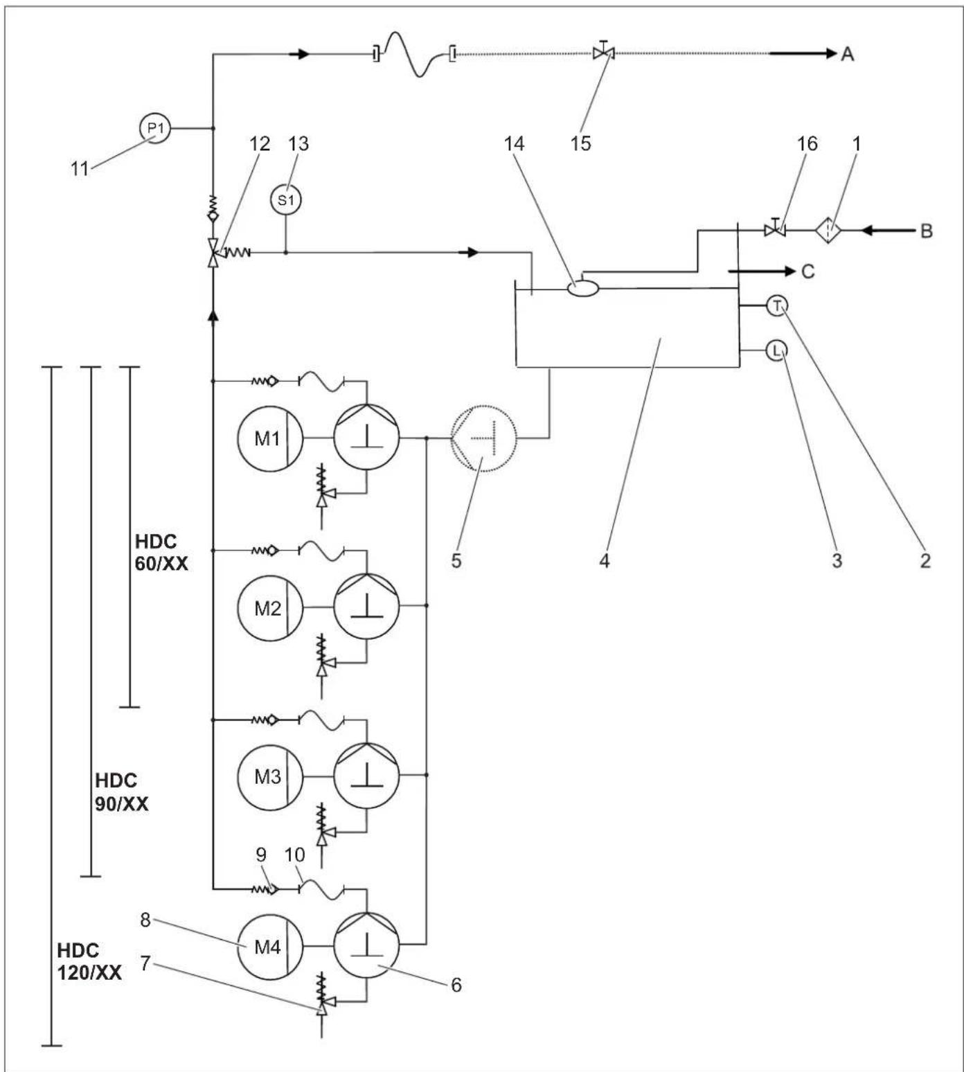
1UJnmaOBnIOBnOBAu(HaYcTaHOBui)
2 DaTmK TemnepaTyPn
3 CnCTema 3ana6irahan y pa3i BiDcyTHOCTI BOIN
4 NonnaBkoBa KaMepa
5 Hacoc nonepeHbOro Tncky
(Onui)
6 KonihBaBnHn Haoc
73an6xHnKJanaH
8 E n e K T p u H n B u r y H
9 3BopoTHiKJanaH
10UNaHnBnCOKOToTCKy
11ДаванВисOKОТСКУ
12 NepenyncknKnaan
13 Bntpatomip
14NonnaBkoBmKnaan
15 3anipHnn Knaan (Ha yCTaHOBui)
16 3anipnKnaanHa yctaHOBUci)
Poaay BODN
Boda BuxoJtB 36aka 3 nonnabueMdo BCMOKtyBaHbHOI cTPOHN HACOa.3aONOMORO nonnabueBOrO Klanana B6aky 3 nonnabueM yTPmYeTBc NOCTHHI pIBeHBoN. PpN bIMoBI nonnabueBOrO Klanana Boda BNlNaBcTaCepe3 nepeynyckHN OTBip. PpN npoyuHeHI BOIONoCTaAHH NuaEeBcNOjDMNeHn npo NOMIKy kepyBaHbHOI CNTTEM 3anobirAHHm He-ctaY BoN.
Hacocu
EneKtpomotop nyckaB xid konihBaHbHH Hacoc. Hacoc noae Body nd BOCKM TCKOM 360ky HaHrtanHa.
CTopoHa BnCokoro TnCKy
Boda niz Bucokm Tnckom Notpanne Yeep3 nepenycknn Knaan Ta daty NK cy do BxOdy BUCOKO TnCKy.CnIOM 3a cmm ide Mepeka Bucokoro TnCKy cnKoBAha.
PerynIOBaHH Tncky
Boda, kka 3aIIMnIacb, nobepHeTbcB iD nepeynckHOr KIanaHa do 6aka 3 nonBaIeM. RaKc bCIO nCKmbAHI BIMKHeH, nepEnyckHNI KNaanMoKHXa NOBHCIO nepeMKHyTN Ha 3BOPoTHNI NOT Do 6aka 3 nonLaBMeJ. RaIoo TtCK H BAIXOJI, He 3BaXaOHu HA BmOKPvCTAHN HnepeynckHOr O KaIanaHa, nepEbnUe MaKcImaIbHN PoobOy N TTK, To BIDkpVbaOTbc 3aONbIKi KNaANH.
CnCTema KepyBaHHa
-3a donomoroKHNKnDe6nkyBaHH npctpi npBodntbca y rotobHCTb do ekcnnyataui. Pnp 3HNKEHH TCKY B CNTeM YCNEXOM BkPNTT pyH OHO NcTOTeNA-po3NIIOHOBaA y BCTAOHBNEH TOUJI NEpEMKaHH, HACOEN BNCOKO TCKY BKIOHAcToBc. Napnn HACOC BKNIOVAe3ype3 aactOTnN nepeTBOPBOaB, INI HACOEN ppaIOIOB npmaIOB pnaMO Bid eNEKTPOMEpEki.
-JaKIO BIMKHyTN BHTpTaTOMip Ha nepenyckHOMY KJANAHI npn ppaOuOHx HACOCAX BWCOKO TNCKY NICr 3aKpTTB BCIX pyHuNxC NICToNETiP03nHIOBaUH, HACOCIN 3HOBY BIMNKaOTbCnICn3aTPMKN, 3HAeHNH RAKOPEYNOCTcBcR.
-Якpo yctaHOBka roToBa ДЯ рo6OTo, a HAcoc BnCOKOro TnCKy He npAIOHObT, To cnPpAOBye TaHMeR, knnicn neBHORc BCTAHOBENHO racy BCTaHOBnHOc YCTaHOBky BVIXdne NOnIOKeHHN.
3axnchi npncptoi
3axnChi npntpO npnaHaeH i nla 3aXnCTy KOpNCTyaBaI He NOBnHIbTy BnBeJeH 3 naY a60 BnKOpNCToByBATINc 3 HUOO METO.
CnCTema 3an06irAHHHeCTaHi BOn,6ak 3 nonJaBcEm
CnCTema 3ana6irahnB iD iBcyTHOCTI BOH 3ana6irae yBMkHeHHIO Hacocic BnCOKOrTO TCKy npn HeCTaHi BOH.
DaTtK TemnepaTpN
DaTtHK TemnepaTpyn BmMkae npctpi npu DoCraHHeH Hi 3aHaTOn BucOkoTtemnepaTpyn BOiN.
3axnctm KOHTaT O6MOTkn
3axmchn KOHTAKT O6MOTKN B O6MOTU MOTOPa HacoCHORO INBMOyBNMKAe MOTOp 3a yMOBN TePMiHOrO nepehabAHtAXEHnA.
3anobixhnnKJanaah
-3anobixhnn KlnanaH BiKpNbBaetbc npn Hecnpab-Hocti nepenyckhoro Knaany.
-3an06xHnnKnIaanHnactpoeHnI onnO6bAHnHa 3a0oJi.HacptoobAHH3diCHIOEbCtTINbKncepBCHOcnyk6bO.
Nepenynckn Knaan3 BntpaTomipom
-JaKIO 3aKnPTN BcIpyHINICTONeTN-po3nHOBaI, BIXKPNEbCnpePENycknknlanA IBCB NO-BepHeTbCn DO NnIaBueBoi KAMEp. BnTpatomip BIXNJUAc HACCO BNCKORO TNCKy NcNRA BCTAHOBHeHOrO aCy 3aTPMNk.
- NocthiHae KIIbKcIbTO BnNepetitKae Haa3d y 6aK 13 nonlaHae Upe3 nepenycknH klnaan.
DaaBau BnCOKOro TnCKy
PnNOBTOPHOMY BIDKPTTI pyuHORIO NICTONETA-POANIJIIOBaua, HACOIN BNCOKO TCKKY 3HOBY pnpraHAnTb piDHNHYEPE3 DAABV BNCOKO TCKY.

1NonnabkoBa kamepa
2NonTbKOBnKnanaH
3ПдкнючehньБODONOCaHн
4 E n e k T p u H n
53anobixhnnknaan
6 AKyMnTOp TCKY
7 P3b6oBa npo6ka oniEbiDnBHorO OTbOpY
8IHaKauaipBnHp onii
9Ma c n Hn 6aK
10 Haoc BncoKoro Tncky
11BeHTnIaTOp3ΦIbTpOM
12TOnOBHHBUMNKay
13Ua4b3Pn6opam06cnyrobyH
14 BunycknH φπibtp
15 NpeenHn nct oBnBkn
16 Hacoc nonepeHboro Tncky (Onua)
17UJnH BRUCOKO TCKY
18 Dmcnnn y H
19 DaTChK TemnepaTyPn
20 CnCTema 3anobirHry pa3i BiDcyTHOCTI BOIN
21 BntpaTOMip
22 DaaBv BnCOKOro TnCKy
23 Pepenynckn Knaan
24 3'eDHaHHBnCOKOrTo nCKy
BVeDeHnB EeknIyTaUio
△HEBE3NEKA
Hebe3eKa mpaamyeaHn! Pucmpiui, nideedeHHn. uanahe bucoko0o mucky ma 3'edohnnnoBuHni Bymu cnpaehi. Jkso cmh e HncpaaHum, mo npucmpiu uKOpucmoeyam He MeKHa.
Eknpnyataia
Ppabnla 6e3nekn
Kopcmyaou nouhen eukopcmooyamu npucmpiy y iodnoiHocmi do Hcmpkui.BH nouhen eapoxoyama umo miueoemci ma 3eepamu yeay na pemix ocib ndacpobom 3 npucpmoe.
He moxha 3auiuamu npucmpi6e3 haiay id hao pobom.
HESE3NEKA
- He6e3neka onekmuza yaproo oedoo! He ha-paenemu uana ha noo e ao meupu.
He6e3neKa oniKy o6 zapnyi enemehmu ycmahoeKu! Ppu pobomi 3 zapayoo 8o0o He mopkamucdo Heizlonboaunxmpybonpoobdie ma unhaie.CmpymunHy mpybky ympumyarmu minbku 3a qauky pykoarnku.
Hebe3neka ompycnna afo ximuoo onky 3aco6amu dny uuehenHa! Dompymyeamuc8kazieok, HaeedeHux Ha ynakoeui 3acob die nuuehen. 36epiaamu 3acib nry uueheny ymicui, heodcmynHomy dna HeynoeohaeJxHux oic6.
HE6E3NEKA
Hebe3neka ypaJaeHHN ENEKpHUN cmpyMn! He naPaaIeMHcmpbHs oOu haNaCmYn npCuMPo!
- enekmpuHi npucpmi ma ycmahoeku,
Ha enacmuo yocmaHo8ky,
- eci yacmu, uo npoeodmcbcmpym y poobouoi 30H.
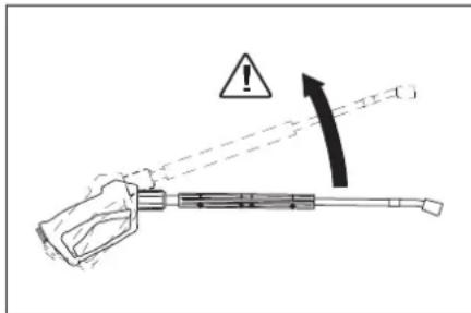
Yepe3 cTpyMiHb BOiN, 0IO BNXOITb 3I cTpyMeHEBoI Tpy6Kn, BnHKAe CnA Bldaui. Yepe3 cTpyMeBEy Tpy6Ky, 0IO MblCTNbTcB niD kyTom, Cnla Die DOHN3y. △HE6E3NEKA
He6e3eKa mpaBmyaHnR! Cuna biodaChi cmpyMunHOI mpy6ku MoXe nopeyyumu eauy pieHOaEy. Bu moXe me enacMu. CMPyMHNA mpy6ku MoXe eunemimmu ma pMybAmu omoyoux nIOeBu6epmb 3pyHy nooio dno pobomma uho ympUyme pyHui nicmonem-po3nIOBaHikono he zakluOme eaxinb pyHozo nicmonema-po3nIOBaHa.
-He Hapnaenmu cmpymih na cebe a6o ha iuux nnoeou dnuoennn o8yau a6o 3ymm.
Hebe3neka dicmammu pmaMy eio cachmuh, 0o iDnilaomby!YnAmku, 0o iDnilaomby, abo npedemmu mojymbmpaMybamu modeu abo meapun. He Hanaenmu cmpyMihb odu Ha nAmki abo Hezakpinneni npdEmmu.
Hebe3eKa aaeiBhAcniok yukodKeHnI Uhu ma knanau ouuama 3 eioani MiHIMy 30 cm. hHEE3NEKA
Hebe3neka, 0u buknkaHa Hebe3neHmu dnn 3do- ope' peoBuHAm! He po3npooyeamu Hacmyni Ma- mepianu, ocikBku e noeimp moxymb nHrmuc He be3neHu nn 3doop' peoBuH:
-a36ecmoBmichi mamepianu,
MamepiAnu, 40, MoKnHueo, MicmTb He6e3neHi dna 3doopoe peovuaH.
HEBE3NEKA
He6e3neKa dicmamu mpamy 6iD euxiohoz cmpyMeH, MoKnueo, aepaoyo boud! HaonmmunbHIie do ycmtaHoeku nixdoamn luepe opuaHbnbl uana bucokoao mucky fipmu Karcher. Ppu uKopucmanhi Hux wnahe japehmiBukno-yaembc.
He6e3neKa dnn 3doop8'ny 38'3ky 3zacmocyeaHnM 3acobie dnn yuueHHa! Yepe3 doabku, npu nompebi, 3acoby dnn yuueHHa, 3numa 3 npcnpo oba e He iidnoeiaekocmi numho odu.
He6e3neka nowkodumu opaahu cnyx niq cac po-bomu 3 yacmuHaMu, uo nocunioomb 3yck! Ucbmy eunadky eapmo Hocumu 3acob 3axucmy op-zaehie cnyxy.
Bibpaia npncToPO
△NONEPENKHEHH
Doeaa mpueanicmb pobom unapamy moze epez eibpaio 3ymoobum npopyuenn Miceeoo kpoeo0biy epykax.
Bn3aHTNTOVHOCACBnKOpCTAHnPnCTPOHOHEMOxNBO,yepe3TeIIOe3aJeKtBbIDBaTaBxo idaktoTIP:
-0oc6ncta cxnlbHicb do npoyuenHa kpoo06iy (qacto xonoHi nalbu, 3y nn buiB).
Hn3ka TemnepaTpya HABKONuHbOro cepedOBuIa. Heo6xioHO HocNTn Tepni pykabNKn dIra 3axNuCTy.
-CnIbHe CTnCKaHHaBAkae KpOo06Biry.
- Be3nepePBbHa po6oTa pnpctpo - Ze rpye, HIX po6oTa 3 npay3Am.
PnpeynpHOMy DOBROMY BIKOPNCaHHI npncTPO Ta npoNOBTOHPOMPOBRI BIDNOBIINHX CMMNTOMIB (Ha-nPKnKlnd,3yD NbaLbux, XOLONDI naLbU) Mn paDNMO npoTIOnObCTeXeHNH y Ikapar.
Ducnnei
PnIMtKa: TeKCT BiO6paXaεTbCraAHRJIiCbKOIO MOBOHO.
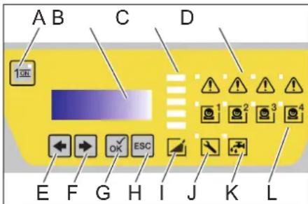
A KhoNka po36nokyBaHHa
B PdkokpncTaniHn DnCnnei
CCTOBINKOBa iHnkaucia (B o6nacti, 10 cTahOBNTb np6bn. 20% BID po3paxyHKOBOR TCKy)
D NobidomJIeHH npo 36iHacoca 1-4
E 3MHHITI 3HAeHENI (-) a6o nepecyHyTN KypcOp HAIJIHO
F3MIMHTN 3HAeHHN (+) a6o nepeCyHyTN KypCop HAPABO
G KhoNka nIDTBepDkeHHRA (OK)
H CkacyBaHHRA (ESC)
I Tuck y cunctemi
J 3araanbHa HenoJaKa
KHectaVaBoDn
L BiDnOBiDHH HACOC BMNAeTbcra
-Пи ротовс即时 сановдdo ekрпатул, BiDobpaхаюсу санчоюн hacocib bKoKTO TCKY ta pOboyn Tnck.
-13 noBOIO NOMINOK, BIDOMOCTI npo HIXBID6paJXaOTbcHa NcNnEITonepeMHHO (DVB. "Onomora npi NOMINKax").
IpeBipntroTOBnHicTbdoeknnyatauii
△HE6E3NEKA
Hebe3nka icamamu pmaMy e0i0h0o cmpymn, moKnuo, zapvOo!
HE6E3NEKA
Ipeepipmu uana Ha npedem NowkoDxehnnerpeo KOKHM eukopucmanHm. Heauno 3amHimb defekmu unane.
→ PepeD KOKHNIM BKNOPCTAHNNEpeBIPRAITEUAnH BRCONKORO TNCKY, Tpy6onpOBOn, apMaTyPi TA CTpyMNHHY Tpy6KY HA HABHBtCb YUKoKDxHb.
→ PpeBipRte MICr 3'edHaHb IaHaHb HaIb-HicThb NocadKa Ta repMeTnHiCTb.
BnKlHHeHHyHaD3BnAaHOMy BnPaKa
IOBepHytroIIOBHN BUMNKAuB NONOKeHHa "0". 3aknTe noDany BOIN.
→ YBIIMKHTb NICTONET-pO3NNIIOBAU, DOKH pPnIaD He 3B1BbHTbBa BIT NKDC.
BbIMKHeHH npncTppo
Bidkpntn noauy BOH.
NObepHyTu rOIOBHN BmNKaay B noJoxeHHra "1".
HaTnCHyTu Ha KnaBiy po36noKyBaHHr.
PpOBeCTMmKy.
PnmuRtKa: Pnp nay3i niq cac YuHcHHeN, uO nepeBmUe BCaHOBHeHn cac 3aTpMnK (MIH. 30 cekyND), npCCTPIYUNHReTbC. ODoHAcHO BCTAOHBOHeTbcpe rnyBoBaHN hac rotOBHOCTI do pOboTN. RaKIO B MexkAs yacyrotOBHOCTI do pOboTN pNI BLkPnBAHHpyHoro nicToTe-PO3nnIOBau naJa TNC, pnpnaD 3anyCKAEbTa CBATOMATNUO.
PiIroTobKa do po6oTo npncTpoko
→HATNCHYTN HA KnaBiy po36nOkyBaHHa.
BmKHy npctpi
→ NObepHyr rnoOBHm BnMnKaay B noNoxKeHHa "0".
3aknnte noaay BOn.
→BIMKHTbPICTONET-po3nNIOBAu, DOKIN npnIaH He 3BilbNHtCB BID TCKY.
→ 3a6nkybntnictoet-po3nnHOBa3a donomoroo 3ano6iXHoro fikcatoBaD BnnaKOBOro HaTNCKAHH.
36epiraHHa
Pn TpBaiNX nepebax y p06ti a6o npn HEmoxNBOCTI BCTAHOBJIeHHa NpCTOPO B MiCJx, 3axuieHINX BiD MOpO3Y, BXITN TaKIN 3axoJiB (DNB. rnaBy "TexHiHe OBCyroBvBaHn Ta DOrJa", po3in "3axnCT BiD Mo-Posi):
3nnte Body
→PpOMnTe npnnaa aHTnOphn3OM
BIMMKHYTu Ta3a6NOKyBaTN RONOBHIN BIMNKaU.
TexHiH XapaKTePnCTnK
PnHbBnKIOeHH BIDNOIBINO Do PernameHy (EC) 2019/1781 DoaToK I Po3in 2 (12): a)
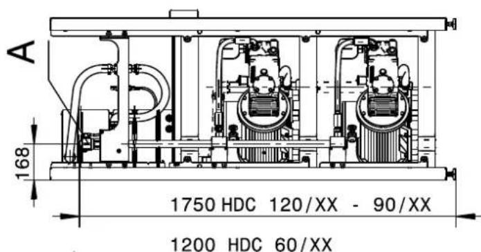

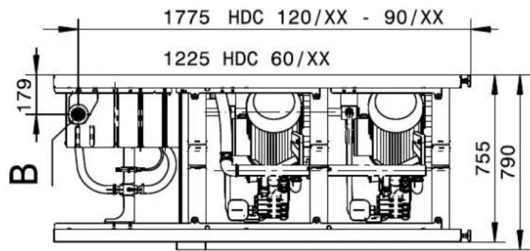
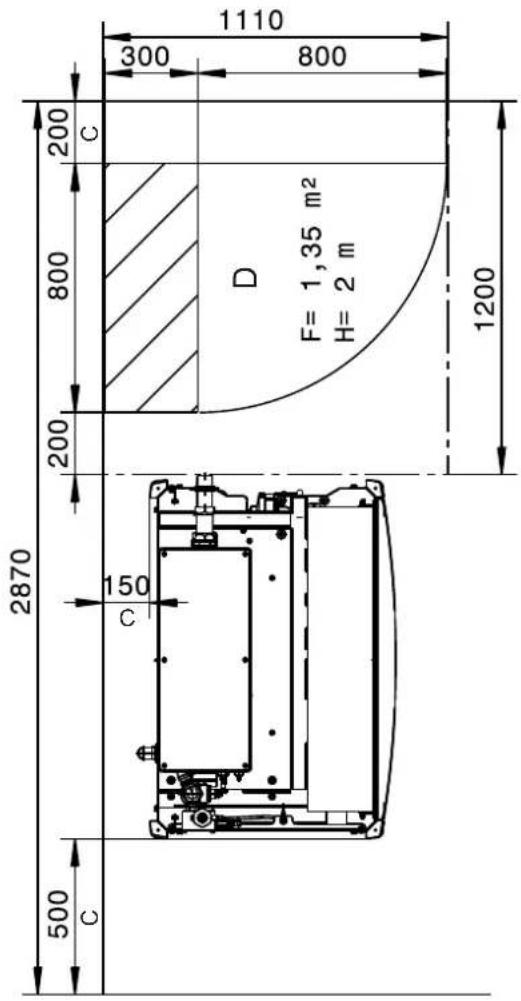
36paenHnHDC120/XX6e3 nucmooeoi 6
WU6KU
A 3'eDHaHnH BnCOKoTmCKy
BπiKnoyeHHBODOnocTaayH
C Minimaihba BicTaHb BiD CTIKN
DПоа,Ky notpe6ye po3noinbua waopa
ⅢaHnF NOaIb BOIM Ta pykAB BVCOKORTO TcKy BIDcHainE.
→Pnucpii NOBHeH npauiOBaTH MaKc.1XB,DOKN HAcoc Ta NiiH He 6ydyTb NcyTMM.
PpomnTe npncptpi 3aco6amn 3axncty BiD MOp03B
BkaibKa: DOpmyTecI hCTpyKu3 3 BkOpncTaHnHaHTNp3y.
3aJIInTe DoBepxBy B6ak 3 nonnabKOM 3BuaHn aHTnDpN3.
BCTAHOBHTNI BNXODOM BNCOKOTUCKYBIIDNO-BiHyEMHICTb.
→ YbIMKHyTN npnCTpi i DaT NMy nonpaOBOATN, DOKI cnpaIOe CNTcEMa 3anobiraHHy y paai HectaHi BODN B BakY 3 nonpauBcem i npnCTpi He BmMKHETCB.
Takox3axntBIDKopo03I
Donomora y BnnaKy HenoJaok
HEB3NEKA
He6e3neKa mpaemyeaHn! Ppu ecix pemohmhu po6o max Heo6xioHO eumukam zuoobu eumukay.

A Homep noMnIKN
B Yncno fakTuHO BuaHx NOMIOK
| Homingo | Опс 3бою Вид по-Минки | 2 |
| 01 Вidiousу | напуга у сисемі керваимя | |
| 02 Дécileй | зь'язok BIDCSYTNII 2 | |
| 10 ВIMКЧ | ЗхИСТУ DBIVΥHA HACOCY BIVCOKOTO TSCKY 1 | 1 |
| 11 ВIMКЧ | ЗхИСТУ DBIVΥHA HACOCY BIVCOKOTO TSCKY 2 | 1 |
| 12 ВIMКЧ | ЗхИСТУ DBIVΥHA HACOCY BIVCOKOTO TSCKY 3 | 1 |
| 13 ВIMКЧ | ЗхИСТУ DBIVΥHA HACOCY BIVCOKOTO TSCKY 4 | 1 |
| 14ЧастOTи | ПлелетВоровачу y Запобіж"HOMУ BIVMКЧУЕВI DBIVΥHA abO чАТOTHИ пe-ретворовч He rotOBи | 2 |
| 18 3axИСНИ | ОБВITКOBИ KON-TaKT HACOCY BIVCOKOTO TSCKY 1 | 1 |
| 19 3axinschni | obBNTKOBII KOH-Takt HACOCY BWCOKO TNCKY 2 | 1 |
| 20 3axinschni | obBNTKOBII KOH-Takt HACOCY BWCOKO TNCKY 3 | 1 |
| 21 3axinschni | obBNTKOBII KOH-Takt HACOCY BWCOKO TNCKY 4 | 1 |
| 26 BvIMNKauch | 3axinsctu DBVfryHa HACOCY nonepedhboro TNCky | 2 |
| 30 BvIMNKauch | "BKn" yBvIMKHeHNI TpINBaJIi Qac (BXiD cnCTeMI KepyBaHnI) | 2 |
| 31 BvIMNKauch | "BKn" BvIMKHeHNI TpINBaJIi Qac (dncplneI) | 2 |
| 32 BvIMNKauch | "BvIKN" yBvIMKHeHNI TpINBaJIi Qac (BXiD cnCTeMI KepyBaHnI) | 2 |
| 40 HeCTaUa | BoDI 2 | |
| 41 3aHaITo | BVCOKA Tempepaty-pa BoDI | 2 |
| 42 UcHyENH | BtOKy 1 (Hapri-KlaI, ShJaanr pOzirpBaHnI) | 2 |
| 43 UcHyENH | BtOKy 2 (HeBeJI-NKn BtTik) | 2 |
| 45ДужЕ BIV | COKN TnCK (>300 6ap) | 2 |
| 46 HeBipHI | CInHan BiD BVtPa-tomipa | 2 |
| 47 Перенист. | KNHKn Klapan HbIpe-rglbobAHNI HeBIPHO | 2 |
| 48 HDC BiD | PegyIbobAHNI HeBIP-HO | 2 |
| 49 HeMaes | CInHany BiD BVtPaTOMIPA | 2 |
| 50 HeMaes | CInHany BiD DaTUnKa BWCOKO TNCKy | 2 |
| 52 HeMaes | CInHany BiD DaTUnKa Tempepatyri | 2 |
Bud nomnkn 1: AabpiHnn peKUM pOboty yctahOBKN 3 HacocAM BUCOKO TNCKY, RkI 3aJIINHJNcB.
-BnD NOMIKK2:ΓOTOBHICTbdo pOBoTn yCTaHOBKn YBIMKHeHa Ta HAcOCh BNCOKOr TmCKy BiDKNIOHyI.
- 韩粵 BUNHKA OJHa 3 BNUEe3r4aHNX NOMANOK, NiC1N y CyHEnK NoMnIKn pNcTpi 3HOy MOxKa HyaBKMHTy, HATMCHYBNI KHNK DEbKOYBAHH.
Pnmitka:OctahHI 40 nomIOK 36epiraObTcB 3 BIDNO-BiHOIO datoIO i acOM i MOKYb BiO6paXaTmC H A dnCnneI.
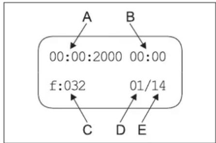
A Data BHHKHeHHN NOMNIKIN
B IIndkaiaqiayacy BHHKHeHHN TOMNIKN
C Homep nomnkn
DMicye cncky nomnIOK
E Yncno 36epexeHnx NOMnIOK
| Hecnpabnictb Moxknblbipnunny Ucny Hennn KIM | |||
| Пистрий не пацюс.У писстор.Y начуг.Nперевити селектуни мереку.Eпектун | |||
| Спрацьално зхасе р龄 motora ддся ССТЕМКеруань. | Перевити зхасиь вимькчдвигуна.Cлужба пidtrрмк | ||
| Hacoc He zanyskaetcbrprn BvBikpntti pyuHOrO nCtOteT-aPoznilnoVBaCh a nduc pexmmy nIaid roKabel. | ЗаминддчNK TSCK abo kabel. | Служба пidtrmpkki kopr-ctybaiv | |
| Tnck y pricstpo He 36InbUeTbcry | Прodуtn Форсуну. | Заминн hacaiky. | Korinctybaiv |
| TpbyonpoBVD HepeMpTeHnN 3i StcOpOnHy c-mokTuBaHN. | Перевити hapi3ni 3'eDHaHNr Ta uJaanHr. | Korinctybaiv | |
| HerepmetvnHn 3aNo6jHn Klnanah. | Перевити reynIOBANH, pri nNotpe6i BCTABITN HoBe yuJIbHeHn. | Служба пidtrmpkki kopr-ctybaiv | |
| Perenyckn knlanah HepeMpTeHnN abo BCTAHOBLeHn Ha 3aHaTOn Hm3bKe 3NaYeHn. | Перевити enemEnn Klanana, pri BnayBneHn i yskoJ-kJeHb 3amHnTn, pri 3a6pydHnO ChcHNTn. | Служба пidtrmpkki kopr-ctybaiv | |
| HecrpabnHKnlanah HaccSy, He zakpHTo Mar- nHTN Knlanah BVCOKO TnCKy. | Заминн HecePapn DiTaI. | Служба пidtrmpkki kopr-ctybaiv | |
| Hacoc BVCOKOrO TnCKy cStykAe, cTpiJika MaHometra sckae | Hacoc BVCOKOrO TnCKY BCMOKType NobITRp. | Перевити ycmokTuBaIHy cStEmy ta pri6paTn BnTIKAHN. | Korinctybaiv |
| Hecnpabna ronibKa abo npjxHn Kaapana. | Заминн HecePapn DiTaI. | Служба пidtrmpkki kopr-ctybaiv | |
| Hacoc nonepedhborO TnCKy HecepRbHn abo NOKHn HAcINOM. | Перевити haoC nonepedhborO TnCKy. | Korinctybaiv | |
| ПоstiHn Bvdkpmbatn Ta zakpmbatn pepeynckn knlanah pri prin mAmHI 0 | Витку TrpobpoBdoBn BVCOKOr TnCKy abo apyHn NICKToT-pOzMnIOBauH HepeMpTeHnN. | Замин Ту уцlbHn MlcSe BtToky. | Korinctybaiv |
| ЗворOTHkn Klananab abo yuIbHeHn rIdo-poz- pOzIaIbNbHnka Ha nepenyckhomy knalanii HerepmetuHnE. | ВiderpoMHyBaTn nepenyckn knalan. | Служба пidtrmpkki kopr-ctybaiv | |
| BIDobpa3BaBcHomep nomilkn 01 | Панел КеруBaHnny uXkoJdKeHo, 3eIeHn CbTTIOJIoHd 6BImaC.. | Перевити паелы керуBaHnny, pri noTpe6i amHnTn. | Служба пidtrmpkki kopr-ctybaiv |
| BIDobpa3aTbC Homep NiomlOk 10, 11, 12 Ta 13 | Спрацьов ВIMKAnч рincSTPO 3axHcSTy bI dpeBaehTaXeHb BIDIOBIDHO RACOCu BVCOKOr TnCKy. | UcyHyTN priUnHy nepeBaHTaXeHnN. | Служба пidtrmpkki kopr-ctybaiv |
| BIDobpa3BaBcHomep nomilkn 14 | Спрацьов ЗanobixkHn BIMKAnч DmHyHn abo chactOTHn nepeTBOPOBauch He rotOBuN | UcyHyTN priUnHy nepeBaHTaXeHnN. | Служба пidtrmpkki kopr-ctybaiv |
| BIDobpa3aTbC Homep NiomlOk 18, 19, 20 Ta 21 | Спрацьов ТерmoDABauch BIDIOBIDHO DmHy. | UcyHyTN priUnHy nepeBaHTaXeHnN. | Служба пidtrmpkki kopr-ctybaiv |
| BIDobpa3BaBcHomep nomilkn 26 | Спрацьов ВIMKAnч рincSTPO 3axHcSTy bI dpeBaehTaXeHb HAccocu NopereDbBoT O TnCKy. | UcyHyTN priUnHy nepeBaHTaXeHnN. | Служба пidtrmpkki kopr-ctybaiv |
| BIDobpa3BaBcHomep nomilkn 40 | Спрацьов рincSTPI ZanobirAnHg pa3i Bld-cyTHocTi BODn B aky 3 noPnabUeM. | UcyHyTN HeCTaCy BoNi. | Korinctybaiv |
| 3aTnHcyTn noPnabUeBv Klanan | Перевити leKicbT xOdy noPnabUeBO rKlanana. | Korinctybaiv | |
| BIDobpa3BaBcHomep nomilkn 41 | Спрацьов ДатчК TempepaTyrn B baky 3 noPnabUeM. | 3MeHsHTn TempepaTyrp noDaCy BoNi. | Korinctybaiv |
| HecnpaBnICTb | Можлелprpinчни | Усуненя | КИМ |
| Вidобразвсяnomерnomilки42Тубо | правID ВICOKOTO TSCKУ HepeMpTeNCHN(BNTIK). | 3найи Та ушільпгп Міце BVENTOKу. Корістувач | |
| Одочасno BIDkpITо 3aHaДTo 6BarTo Cnoxu-Baiv. | 3akpITNo CnoXuBauC. KoprstYBaU | ||
| Давач ВICOKOTO TSCKУ HepePabNHIЗ 3amInHTI | davay Tsck.Слжба підtrpIMKn Kopr- | ctyaBviv | |
| Вidобразвсяnomernomilки43Тубо | правID ВICOKOTO TSCKУ HepeMpTeNCHN(BNTIK). | 3найи Та ушільпгп Міце BVENTOKу. Корістувач | |
| Давач ВICOKOTO TSCKУ HepePabNHIЗ 3amInHTI | davay Tsck.Слжба підtrpIMKn Kopr- | ctyaBviv | |
| ВidобразьЯБСЯnomilкa homep45 | ДужЕ ВICOKOTO TSCK (>300бap). | Встановлеса HepePabINbHA Форсунka.Встановпtn ppa-BinbHy Форсуну. | KorinCTyBaV |
| Давач ВICOKOTO TSCKУ HepePabNHI | 3amInHTI DaTchK TSCKу abO KaBeIb. | Слжба підtrpIMKn Kopr-ctyaBviv | |
| ВidобразьЯБСЯnomilкa homep46Ви | patomip podaE сngHaN BnTPatNi >50 n/xb,хoЧа Haoc He npaIoo. | Перевироти ВитрatomiP, рп NeobxIDnocti 3amInHTI. | Слжба підtrpIMKn Kopr-ctyaBviv |
| ВidобразьЯБСЯnomilкa homep47(xoча задань TSCK He doceRhyto,Вбaki3 nonpabueM nepeteknlo 6iIbSe 400 litripв Bodи за 6iIbsh HIX 25 sekyund) | Перетуckнй кланan BIDperetylnbOBAHni He-paBnblHo. | Правиьно BIDperetylnbOВати nepetуckнй кланan.Слжбa | підtrpIMKn Kopr-ctyaBviv |
| Перетуckнй кланan HepePabNHI. 3amInHTI | петуckнй клан.Слжбa підtrpIMKn Kopr- | ctyaBviv | |
| В мeнIO Display zadANO HepePabINbHe 3na-ychNHЯЗANO TSCKу. | ВьeNTи павиьно 3nauchENHЯ 3adANO TSCKу.Слжбa підtrpIMKn Kopr-ctyaBviv | ||
| Давач ВICOKOTO TSCKУ HepePabNHI | 3amInHTI DaTchK TSCKу abO KaBeIb. | Слжба підtrpIMKn Kopr-ctyaBviv | |
| ВитраTomip HepePabNHI. | 3amInHTI BITparOMip. | Слжба підtrpIMKn Kopr-ctyaBviv | |
| ВidобразьЯБСЯnomilкa homep48Вмe | mIoD Display zadANO HepePabINbHni TINHDC. | Встановп.TIN HDC яk Advanced. | Слжбa підtrpIMKn Kopr-ctyaBviv |
| ВidобразьЯБСЯnomilкa homep49 | Hemae сигану bID BnTPatOMIPA. | Перевироти ВитрatomiP, рп NeobxIDnocti 3amInHTI. | Слжбa підtrpIMKn Kopr-ctyaBviv |
| ВidобразьЯБСЯnomilкa homep50 | Hemae сигану bID дabaya ВICOKOTO TSCKу. | Перевироти Датчк TSCKу i KaBeIb, рп NotpebiЗamInHTI.Npeebiprtn Плату A5. | Слжбa підtrpIMKn Kopr-ctyaBviv |
| ВidобразьЯБСЯnomilкa homep52Hemae | сигану bID dAtpNka TempepatуriВ6akу iЗnonpabueM. | Перевироти Датчк Tempepatуri i KaBeIb, рп NotpebiЗamInHTI.Npeebiprtn Плату A5. | Слжбa підtrpIMKn Kopr-ctyaBviv |
Akcocyapn
3acibdnyuHn
BukopncTahn 3ac6y dny uHneHH nonerWye npoeC ouHHeHH. Y Tabniu npedctabNeHo nepenik 3ac6ib dny uHHeHH. Npeed BnkOpncTahnM 3ac6ib dny uHHeHH obo8rKBO npOHTaN BkazIK H aynakobci.

Chairman of the Board of Management
S. Reiser
Director Regulatory Affairs & Certification
YnOBHOaKeHn cnBpO6iTHNK NO BeeHHo DOKyMeHTo-06iry:
S. Reiser
Alfred Kärcher SE & Co. KG
71364 Winnenden (Germany)
Tel.: +49 7195 14-0
Fax: +49 7195 14-2212
Winnenden, 2021/02/01
Fapantria
YKOxHII KpaHI DiIOb YMOB rapaHTI, BDAHAI HAWIMM KOMNETEHHMNI TOBAPCTBAMN 3i 36yT. MoxNBIHEcnpabHOCTI pINaNDy npOTAR mapAHITHORO CTPOKY MN YCyBAeMoE 6BeKoTBoHNO, kAIO pNmHnONJRAE B DeFekTxMATEpianIB a60 NOMIKAK NPN BMTOBNEHHI.
Register your product and benefit from many advantages.
www.kaercher.com/welcome ★★★★★
Rate your product and tell us your opinion.
www.kaercher.com/dealersearch
Alfred Kärcher SE & Co. KG
Alfred-Karcher-Str. 28-40
71364 Winnenden (Germany)
Tel.: +49 7195 14-0
Fax: +49 7195 14-2212