
RS PRO 5150 SC - Lamp STEINEL - Free user manual and instructions
Find the device manual for free RS PRO 5150 SC STEINEL in PDF.
User questions about RS PRO 5150 SC STEINEL
0 question about this device. Answer the ones you know or ask your own.
Ask a new question about this device
Download the instructions for your Lamp in PDF format for free! Find your manual RS PRO 5150 SC - STEINEL and take your electronic device back in hand. On this page are published all the documents necessary for the use of your device. RS PRO 5150 SC by STEINEL.
USER MANUAL RS PRO 5150 SC STEINEL
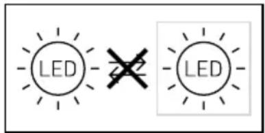
GB 12 Follow written instructions!
Start-Up/Spanningsunterbrechung
Please read carefully and keep in a safe place.
-Under copyright. Reproduction either in whole or in part only with our consent.
-Subject to change in the interest of technical progress.
Symbols

Hazard warning!

Reference to other information in thedocument.
2. General safety precautions

Disconnect the power supply before attempting any work on the unit.
- During installation, the electric power cable to be connected must not be live. Therefore, switch off the power first and use a voltage tester to make sure the wiring is off-circuit.
-
Installing the sensor-switched light involves work on the mains voltage supply. This work must therefore be carried out by a qualified electrician in accordance with applicable national wiring regulations and electrical operating conditions. (e.g. DE - VDE 0100, AT - ÖVE-ÖNORM E8001-1, CH - SEV 1000)
-
Only use genuine replacement parts.
- Repairs and battery changes must only be carried out by specialist workshops.
- The emergency-light system must be installed in compliance with national regulations and regularly tested for proper working order.
3. RS PRO Connect 5100/5150 SC RS PRO Connect 5100/5150 SC EM RS PRO Connect 5100/5150 C
Proper use
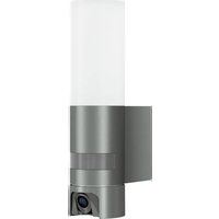
RS PRO Connect 5100/5150 SC
-Sensor-switched luminaire with active motion detector also suitable for installing in rooms exposed to moisture.
-Limited suitability for outdoor use as a result of detection sensitivity.
Note:
Make sure that the light is installed at a minimum distance of 3m from any Wi-Fi routers or Access Points.
Proper use
RS PRO Connect 5100/5150 SC EM
-Sensor-switched light with active motion detector also suitable for installing in rooms exposed to moisture.
-Limited suitability for outdoor use as a result of detection sensitivity.
-Integrated emergency light (EM).
Proper use
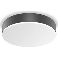
RS PRO Connect 5100/5150 C
Light without active motion detector also suitable for installing in rooms exposed to moisture.

Suitable for use in an environment in which conductive dust is expected to settle on the light.
How sensor-switched lights work
The integrated HF sensor emits high-frequency electromagnetic waves (5.8 GHz) and receives their echo. The change in echo caused by the slightest movement within the light's detection zone is detected by the sensor.
A microprocessor then issues the switch command "switch light ON". Detection is possible through doors, panes of glass or thin walls.
Note: The high-frequency power of the HF sensor is approximately 1 mW - 1000 times less than the transmission power of a mobile phone or microwave oven.
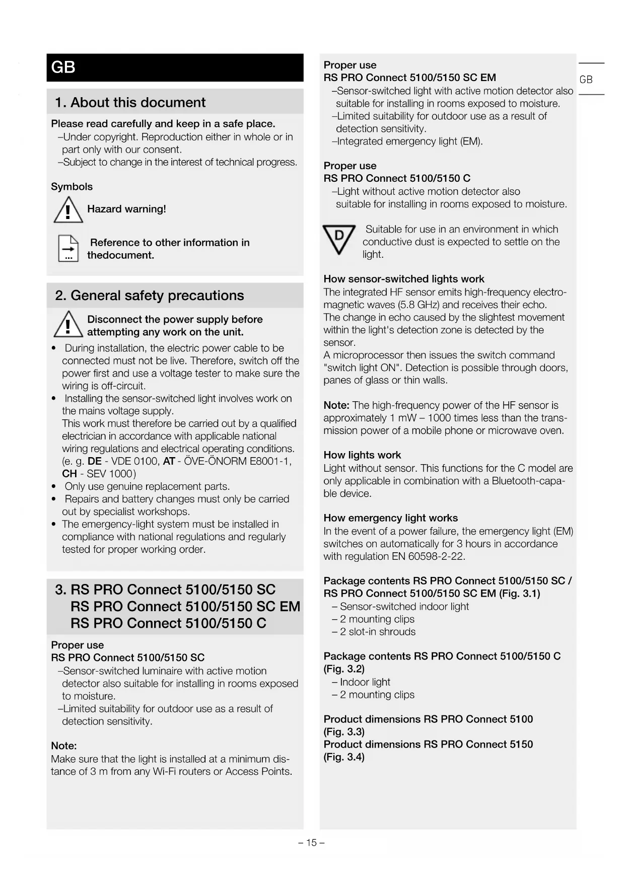
How lights work
Light without sensor. This functions for the C model are only applicable in combination with a Bluetooth-capable device.
How emergency light works
In the event of a power failure, the emergency light (EM) switches on automatically for 3 hours in accordance with regulation EN 60598-2-22.
Package contents RS PRO Connect 5100/5150 SC / RS PRO Connect 5100/5150 SC EM (Fig. 3.1)
- Sensor-switched indoor light
-2 mounting clips - 2 slot-in shrouds
Package contents RS PRO Connect 5100/5150 C (Fig.3.2)
- Indoor light
-2 mounting clips
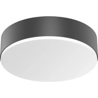
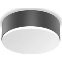
Product dimensions RS PRO Connect 5100 (Fig.3.3)
Product dimensions RS PRO Connect 5150 (Fig.3.4)
Product components
RS PRO Connect 5100/5150 SC /
RS PRO Connect 5100/5150 SC EM (Fig. 3.5)
A Screwed cable gland
B Twist lock
C Connecting terminal
D Mounting clamp
E End caps
F Light enclosure
G HF sensor
H Slot-in shroud
Product components
RS PRO Connect 5100/5150 C (Fig. 3.6)
A Screwed cable gland
B Twist lock
C Connecting terminal
D Mounting clip
E End caps
F Light enclosure
Detection zones for ceiling mounting 1 - 10m
(Fig. 3.7)
Detection zones for wall mounting 1 - 10m (Fig.3.8)
Luminous intensity distribution: (Fig. 3.9 - 3.14)
4. Electrical connection
Wiring diagram (Fig. 4.1)
The supply lead consist of three wires:
L = phase conductor (usually black, brown or grey)
N = neutral conductor (usually blue)
E = protective-earth conductor (green/yellow)
If you are in any doubt, identify the conductors using a voltage tester; then disconnect from the power supply again. Connect phase (L), neutral conductor (N) and protective-earth conductor (E) to the plug-in terminal.
Important:
Incorrectly wired connections will produce a short circuit later on in the product or your fuse box. In this case, you must identify the individual conductors once again and reconnect them.
A mains power switch for turning the unit ON and OFF may of course be installed in the mains supply lead.
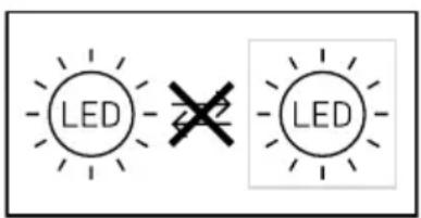
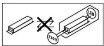
Note: The light source of this light cannot be replaced. If the light source needs to be replaced (e.g. at the end of its service life), the complete light must be replaced.
5. Mounting
- Check all components for damage.
- Do not use the product if it is damaged.
- When installing the sensor-switched light, make sure the installation site is not exposed to vibration.
- Select an appropriate mounting location, taking the reach and motion detection into consideration.
Note: for wall mounting, the light must be installed horizontally.
Mounting procedure
- Switch OFF power supply (Fig. 4.1)
Mark drill holes (Fig. 5.1) - Drill holes and insert wall plugs (Fig. 5.2)
- Screw on mounting clips (Fig. 5.3)
- Fit light enclosure (Fig. 5.4)
- A click confirms proper engagement
- Open screwed cable gland and twist lock (Fig. 5.5)
- Guide connecting cable through screwed cable gland and twist lock and connect to plug-in terminal (Fig. 5.6)
- Close screwed cable gland and twist lock (Fig. 5.7)
- Switch ON power supply (Fig. 5.7)
6. Function
Factory settings (as delivered)
-Reach setting: max.
-Main light time setting: 10 sec.
-Basic light time setting: 1 min
-Twilight setting: 2000 lux
-Basic light dimming level: 50%
Please refer to the technical documentation at: www.steinel.de to put the product into reference mode.
To configure the light, you must download the STEINEL Connect app from your app store. You will need a Bluetooth-capable smartphone or tablet.

Android

iOS
If the light is not configured with the app, it will work as an independent sensor-switched light with the given factory settings.
DC operation
During DC operation, the light output is set to 100% .
Start-up/interruption to power
If the connection to the mains voltage is interrupted, the settings and current operating status of the light will be saved and restored once the power supply is re-established.
Reach adjustment
The reach setting can be infinitely varied between 1 and 10m . Reach can be reduced in four directions by fitting the slot-in shrouds included.
- Open twist lock (Fig. 6.1)
- Pull end cap out by approx. 7 cm. Screwed cable gland need not be undone. (Fig. 6.2)
- Fit slot-in shrouds (Fig. 6.3)
- Push end cap back and close twist lock (Fig. 6.4)
Reach setting examples (Fig. 6.5)
This function for the C models is only applicable in combination with a Bluetooth-capable device.
Time setting
The light's ON time can be set to any period from 5 seconds to 60 minutes. Any movement detected before this time elapses will restart the timer.
This function for the C models is only applicable in combination with a Bluetooth-capable device.
Basic light level
The brightness of the basic light level setting can be varied between 10% and 50% .
The period for which the basic light level remain ON can be infinitely varied between 10 minutes and 30 minutes, or set to remain ON all night.
Main light level
The brightness of the main light level setting can be varied between 50% and 100% .
Twilight setting
The chosen response threshold can be infinitely varied from 2 to 2000 lux.
This function for the C models is only applicable in combination with a Bluetooth-capable device.
Grouping
The RS PRO 5100/5150 SC / RS PRO 5100/5150 SC EM / RS PRO 5100/5150 C can be operated as a separate luminaire or several luminaires can be interconnected in groups via wireless communication.
In each group, a group master must be defined in the Steinel Connect App. All luminaires in a group operate in the same way as the group master is configured. Reach can be set individually for all luminaires in the lighting group.
Cyclical battery checks limit the suitability of the RS PRO 5100/5150 SC EM as group master. The sensor is deactivated during the self-testing phases. This means that the luminaire is unable to detect movement during this period.
This function for the C models is only applicable in combination with a Bluetooth-capable device.
Fade Time
Fade Time can be used to set the rate of dimming when switching the light ON and OFF (1 s - 3 s).
Neighbouring-light function
The neighbouring-light function can be activated and deactivated via the Steinel Connect App. This function assigns the neighbouring groups to the active lighting group. The active group responds to activation signals from the neighbouring group assigned to it and switches to main light or basic light as defined in the settings.
Emergency light (EM)
The "Emergency light (EM) status indicator" is provided in the form of a two-colour status LED at the sensor-switched luminaire.
-Status LED intermittent green:
Rechargeable battery regeneration
-Status LED permanently green:
No malfunction / normal state
-Status LED permanently flashing red:
Rechargeable battery faulty / battery charge too low
-Status LED intermittently flashing red:
Light not connected or faulty
-Status LED dark:
Mains power or emergency light control gear faulty
7. Maintenance and care
Maintenance
For maintenance and inspection, follow the regulations and standards applicable to the emergency light at the place of installation. Emergency lights and emergency-light control gear must be checked at regular intervals.
Startup
Started up by:
Startup date:
Self-tests "EM"
- The self-tests for the sensor-switched luminaire, status LEDs and rechargeable batteries are performed automatically about every 8 days.
-Self-testing battery capacity by simulating a mains power failure is done four times a year.
The sensor-switched luminaire continues to provide main light illumination and sensor detection during the test.
The self-test is no substitute for the function check prescribed in national regulations for emergency-light illumination.
Checks by the user "(EM)"
- The LED status indicator as well as sensor-switched luminaire must be visually checked for proper working order once a month.
Changing rechargeable batteries "EM")
The rechargeable batteries must be replaced if the emergency-light module's status LED permanently flashes red.
- Rechargeable batteries must be changed by the manufacturer. Customer service: STEINEL (UK) Limited 25 Manasty Road, Axis Park Orton Southgate Peterborough, PE2 6UP Service Hotline: 01733 366700
-
Contact the manufacturer beforehand to make sure that the relevant replacement luminaire is available. Two options:
-
Replacement with a sensor-switched luminaire overhauled by STEINEL with new rechargeable batteries (flat-rate service charge).
-Replacement with a new sensor-switched luminaire (concessionary purchase price). - Then send back removed sensor-switched luminaire.
Battery regeneration "EM")
After starting up for the first time (also after changing rechargeable battery or rectifying a fault) the emergency-light control gear regenerates the rechargeable batteries automatically.
Three cycles are carried out. A cycle consists of a 24-hour battery charge and full discharge via the sensor-switched luminaire in emergency mode. Battery capacity is not measured while cycles are in progress. The battery regeneration process is neither carried out after the rechargeable battery discharges in the normal way nor after self-testing battery capacity.
Cleaning
The sensor-switched luminaire can be cleaned with a damp cloth (without detergents) if dirty.
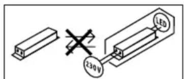
Important: The control gear cannot be replaced.
8. Disposal
Electrical and electronic equipment, accessories and packaging must be recycled in an environmentally compatible manner.

Do not dispose of electrical and electronic equipment as domestic waste.
EU countries only:
Under the current European Directive on Waste Electrical and Electronic Equipment and its implementation in national law, electrical and electronic equipment no longer suitable for use must be collected separately and recycled in an environmentally compatible manner.
9. Declaration of Conformity
Hereby, STEINEL Vertrieb GmbH declares that the radio equipment type RS PRO 5100/5150 SC / RS PRO 5100/5150 SC EM is in compliance with Directive 2014/53/EU. The full text of the EU declaration of conformity is available at the following internet address: www.steinel.de
10. Product liability
The requirements defined in standard EN60598-1 regarding safety must be met after installing the emergency lighting luminaire. The user of the emergency-light control gear is responsible for meeting this standard.
The manufacturer shall not accept any liability in the event of failure to observe this standard.
STEINEL shall accept no liability for direct, indirect or incidental damage resulting from improper use or use not expressly permitted by STEINEL. STEINEL not accept any liability either for damage claims made by third parties on the basis of improper use or use not expressly permitted by STEINEL. The emergency-light control gear must not be opened or in any way modified. Components of the emergency luminaires must only be replaced with genuine replacement parts and by STEINEL itself.
If the emergency-light control gear shows damage suggesting that any safety operation cannot be ensured, the sensor-switched luminaires must not be put into operation. STEINEL reserves the right to change depictions, weights, dimension tables or other such details in the catalogue or operating instructions without notice if this is shown to be appropriate or is the result of technical progress.
11. Manufacturer's Warranty
As purchaser, you are entitled to your statutory rights against the vendor. If these rights exist in your country, they are neither curtailed nor restricted by our Warranty Declaration. We guarantee that your STEINEL Professional sensor product will remain in perfect condition and proper working order for a period of 5 years.
We guarantee that this product is free from material, manufacturing- and design flaws. In addition, we guarantee that all electronic components and cables function in the proper manner and that all materials used and their surfaces are without defects.
Making Claims
If you wish to make a claim, please send your product complete and carriage paid with the original receipt of purchase, which must show the date of purchase and product designation, either to your retailer or contact us at STEINEL (UK) Limited, 25 Manasty Road, Axis Park, Orton Southgate, Peterborough, PE2 6UP, for a returns number. For this reason, we recommend that you keep your receipt of purchase in a safe place until the warranty period expires. STEINEL shall assume no liability for the costs or risks involved in returning a product.
For information on making claims under the terms of the warranty, please go to www.steinel-professional.de/garantie
If you have a warranty claim or would like to ask any question regarding your product, you are welcome to call us at any time on our Service Hotline 01733 366700.

12. Technical specifications
| RS PRO 5100/5150 SC RS PRO 5100/5150 SC EM RS PRO 5100/5150 C | |||
| Dimensions(H × L × W) | RS PRO 5100: 58 × 1370 × 87 mmRS PRO 5150: 58 × 1500 × 87 mm | ||
| Power supply 220-240 V / 50/60 Hz | |||
| Power consumption(Pon) | RS PRO 5100: 31 W / 4250 lm / 137 lm/WRS PRO 5150: 42 W / 5900 lm / 140 lm/W | ||
| Colour temperature 4,000 K (neutral white) | |||
| Colour rendering index R | a = 82 | ||
| Colour consistencySDCM | Initial value: 3 | ||
| Power factor 0.93 | |||
| Mains current RS PRO 5100: 142mA | RS PRO 5150: 194mA | ||
| Average rated life expectancy | L70B50 at 25°C: 60,000 hrs | ||
| Luminous intensity distribution | RS PRO 5100 SCRS PRO 5150 SC | RS PRO 5100 SC EMRS PRO 5150 SC EM | RS PRO 5100 CRS PRO 5150 C |
| HF technology 5.8 GHz (responds to the slightest movement regardless of temperature) | - | ||
| Angle of coverage | 360°, with 160° angle of aperture(if applicable, through glass, wood or stud walls) | - | |
| Mounting height | max. 3.5 m | - | |
| Reach | Ø 1-10 m | - | |
| Max. area covered | approx. 50 m² | ||
| Basic light level | 10-50% | - | |
| Main light level | 50-100 % | - | |
| Time setting | 5 sec - 60 min + install mode | - | |
| Twilight setting | 2-2000 lux + teach-in mode | - | |
| Ambient temperature | -20°C to +40°C | ||
| IP rating | IP 66 | ||
| Protection class | II | ||
| Material | PC IK07 | ||
| Standby, network (Pnet) 0.40 W | |||
| Standby, sensor (Pst) | 0.40 W | ||
| Through-wiring max. 16 | A | ||
| Bluetooth frequency 2.4 | 2.48 GHz | - | |
| Bluetooth transmitter power | 5 dBm / 3 mW | - | |
| Emergency-light battery type | - | Lithium iron phosphate (LFP) | - |
| Operating voltage | - | 3.2 V | - |
| Emergency-light output | - | 4 W / 687 lm | - |
| Emergency lighting duration | - | 3 h1 | - |
| Energy efficiency class | This product contains a light source of energy efficiency class “C” | ||
1 Maximum capacity only ensured by using rechargeable batteries provided.
13. Troubleshooting
| Malfunction Cause Remedy | ||
| Sensor-switched light without power | ■ Fuse has tripped, not switched ON, break in wiring | ■Activate, change fuse, turn ON mains switch, check wiring with voltage tester |
| ■Short circuit in mains power supply lead | ■Check connections | |
| ■Any mains switch off | ■Switch on mains power switch | |
| Sensor-switched light will not switch ON | ■Incorrect twilight setting selected | ■Adjust setting |
| ■Mains switch OFF | ■Switch on | |
| ■Fuse has tripped | ■Activate, change fuse, check connection if necessary | |
| Sensor-switched light will not switch OFF | ■Continuous movement in the detection zone | ■Check zone |
| Sensor-switched light switches ON without any identifiable movement | ■Sensor-switched light installed on a surface exposed to vibration | ■Securely mount enclosure |
| ■Movement occurred, but not identified by the observer (movement behind wall, movement of a small object in immediate lamp vicinity etc.) | ■Check zone | |
| Sensor-switched light does not switch ON despite movement | ■Rapid movements are being suppressed to minimise malfunctioning or the detection zone you have set is too small | ■Check zone |
| ■Mains power supply lead connected the wrong way round (L and N) | ■Check connections L and N or test phase | |
| Status LED permanently flashes red | ■Rechargeable battery faulty (insufficient capacity or break in battery supply cable) | ■Wait for battery to recharge (alarm is reset as soon as the fault is rectified). |
| Status LED intermittently flashes red (only shows after next self-test) | ■Sensor-switched luminaire not connected | ■Connect sensor-switched luminaire |
| ■Sensor-switched luminaire faulty | ■Replace sensor-switched luminaire | |
| Status LED dark despite connection with mains power supply (longer than 5 min.) | ■Supply voltage faulty | ■Check mains power and make sure it is switched ON |
| ■Emergency light control gear faulty | ■Replace emergency light control gear | |
| Emergency light LED OFF | ■No mains power | ■Check mains power and make sure it is switched ON |
| ■Mains power has been interrupted for at least 4 h | ||
| ■Emergency light faulty | ■Replace sensor-switched luminaire | |
FR
Netspanning of moodlicht-driver defect
Akun elvytys " (EM)"
8, Aristofanous Street, GR-10554 Athens
Telefon: +30 210 321 2021
lygonis@otenet.gr
Hatotavolsagbeallitas
Vymena akumulatoru ,(EM)"
Regenerate accumulator ,(EM)"
VP ELEKTRO-PROJEKT D.O.O.
SREDNJE BITNJE 70
4209 ZABNICA
Tel.: 040 856-555 / 059 365-750 (-751 / -752)
www.veleprodaja-ep.si
Tehaseseaded (tarneseisund)
-Ulatuskauguse seadistus: max
-Peavalguse ajaseadistus: 10 sek
-Pohivalguse ajaseadistus: 1 min
-Hämaruseseadistus: 2000 lx
-Pohivalguse hammadustase: 50%
- lamna 6e3 akTINBHO DaTnIka DnBxKeHn TaKKe NOxOHT Iy yCTaHOBKn B NOMEueHnx C NOBbIWeHHo BJaXHOCTbIO.

Iopxodnt Ipnolb3OBaHnB CpeDe, B KOTOpON BO3MOXHO OceDaHne TOKOPOBODaeN Pbln Ha JAmny.
Функции ceHCOPHOn JAmNbI
BCTpoEHbI B4-ceHCOP NocbIaET BbICOKOyAcTOTHbIe 3JIeKTpOMaHNTHbIe BOJIHbI (5,8 ITU) I npHIMaETnx 3xo. PnCamOM He6oJIbSWOM DIBNXeHmB 30HeOBHapYKeHnCBETINbHnKa CEHCOP BOCpNHNMaETN3MeHENr 3xO.
MnKpOIpoUeCCOp Jaet KOMaHny nepeKJIIOueHnna, BkIouHTb CBeT. Bo3MOxHO 6OBApYKeHne uepe3 DBepN, OKOHhIe CTeKJa UIN CTeHbl.
Yka3aHne: MoHocB B4-ceHCopa coCTabJIaRt OK. 1 MBT - 3TO BCErO JINb OJHa TbICrHnA MOUHOCTN, N3JyuaeMoCOTOBbIM TeJeFOHOM UIN MUKPOBOHOBIO NeybIO.
YCTaHOBka DaJIbHOCTn DeIeCTBnA
PaNyc DeiCTBnMoXHO PnABHO peYnIPOBaTb OT 1do 10 M.3a cHT yCTaHOBKn PrinnaRaembIX 3acNoHOK MoXHO yMeHbUHTb paNyc DeiCTBn B YeTbIpex HaPpAbJIeHNJx.
- OTKpbIbTb NOBOPoTHbl 3aTBop (pnc.6.1)
- CHaTb 3aRnLyuKy npM. Ha 7 cm. YrNtHnTeIbHbI KaBeIbHbI BBOID CHIMaTb He HApO. (pnc.6.2)
- YcTaHOBnTb BCTaBHbIe 3acIOHKn (pnc.6.3)
CDBINHyTb 3aRnyuKy Ha3aI N 3aKpbITb NOBOPOTbI 3aTBOp (pnc.6.4)
PpIMepbpeyInpOBKn daJIbHOCTN DeIcTBnA (pnc.6.5)
3TaФyHKUINKacaeTcRTOJbKO BapnaHTa C B coYeTaHnC DaTnKOM Bluetooth.
HacTpoIka BpeMeHN
XeIaemyIO npOIOJKNITJIbHOCTb OCBUeHnRAoHIO pIaBHO OTpeRyIpOBaTb B DnaPAn3OHe OT PRTN CeKHyD IO 60 MnHy.T. IIO6oe DmXKeHne, oShApYKeHHoe Do nCTeueHn 3TOBOBpEmHi, nepe3aNyCTn TaMep.
3TaФyHKUЯ KacaTcra TOnbKO BapnaHTa C B coYeTaHnC DaTnKOM Bluetooth.
OCHOBHON HAnpaBnEHHb CBET
ЯрковochoBHOHaPpAbeHHOro CBeTa MoKHO NaHTpoNTb BДиana3OHe ot 10%do 50%.
ДлгпрдогхительнocOCHOBHOrHa npabNeHHORO CBeTa MoxHo ПлвHO OTpeRyInpoBaTb B ДиЯпЗоHe OT 10do30MHHTИIyUCTaHOBuTb 3HaueHne «Ha BCIO HOHy
OCHOBHO CBET
JpkocTb OCHOBHO CBeTa MOXHO HaCTpOHTb B Dnana-30He oT 50% do 100%.
Hactpoika pexnma cymepek
Tpe6yembl nopor cpa6aTaBHaHna JAmMb MoKHO pIaBHO OtperynipoBaT B Dnana3OHe ot 2 do 2000 IIOKC.
3TaФyHKUЯ KacaetcT OJbKO BapnaHTa C B coYeTaHnC DaTnKOM Bluetooth.
PpynnnpOBka
Mожно Испοльзова rb RS PRO 5100/5150 SC / RS PRO 5100/5150 SC EM / RS PRO 5100/5150 C KaK OTdJIbHbI CBeTNJIbHnK nIi OБbeIINHTb HeCKOJIbKO CBeTUNbHnKOB B rpynnbl IocpeIcTBOM paIIOKOMMyHKaLIn.
B kaKdoI rpynne Heo6xOIMO onpeJeINb B npInloXeHN Steinel Connect App MacTepa rpynnbl. Bce CBETNbHNI K ONDHrpynne npn 3TOM DeiCTByOT aHaIOruHNO KOHpHrypaunM aCtepa rpynnbl. PaDnyc DeiCTBmro MoXHO OTpeRynpoBaTb INDINBIDyaJIbHO DnRA BCEX yAcTHNKOB rpynnbl.
RS PRO 5100/5150 SC EM no npuHne uKnuecknx npOBepOK aKKyMylrTopOB TOnbKO yCNoBHO nOxDxOINT B KaueCTBe MaCTepa rpynnbl. Bo BpemAa3 camokOHtpoJIe CeHCOP DeakTbUbpObaH. Tem CaMbIM CBeTuJIbHNK B 3TO BpEMr He MoKeT paCnO3HaBaTb DInJKeHnI.
3TaФyHKUЯ KacaetcTToIbKO BapnaHTa C B coYeTaHnC DaTNUKOM Bluetooth.
Bpem3atyxaHn
Bpem3aTyxHnMoXHo NcIOnb3ObaTb IJRA HacTpoK KpUBO3aTeMHeHn Pn BkJIIOueHn IN BblKJIIOueHnn (1-3 c).
ФункиrococedCTBa
Функлю COCEДТВа можно akTNBирOBaTы Ип deakTNBирOBaT NOcpeDCTBOM npinloKeHn Steinel Connect App. Пи ETOM COSEДНe Гупь Ha3HaayOT- ся akTNBHOpyPnne CBETINbHnKOB. Гупna Cnyшaet CINHAJIBy BKJIOUeHnHa3HaueHNoE nCOSEнгуПьI И COOTBETCTBeHNO NepeKJIQUaET HaCTpOuKn Ha OCHOB- Hoe OCBESeHn Ип BA3OBy IO rpkOCTb.
AbaruHoe oCbeueHne (EM)
HnKauNcoTcHnAabpHnHOOCBeueHn (EM)OTobpaKaETcNoCpeCTBOM DByXuBeTHOro CBeToNDOda COCTaHnHa CeHCOPHOM CBeTNbHnke.
CBeToIOIO COCTOHHI npepbIBNCTO MmraET 3eHbIM: BocctaHOBJIHeHne 6aTapeiKn
-CBeToIIOI COCTOHHI TOpNT 3eJIeHbIM: Het HeNCpabHOCTN / HopMaJIbHOe COCTOHN
CBeToIOIOcOCToHnI NOCToHHo Mmraet KpaChbIM: HenCnpaBhIe 6aTapeuKn / HeNoctaToHbI 3apJd 6aTaapeuKn
CBeToIOIOI COCTOHNIpepbIBNCTO MmraET KpaChbIM: JAmna He NOKIOUeHa Nn HncpbaHa
CBeToIOIO,COCTOHHaTMMbI:C6oI cTeBOrHaHpaJKeHnI HnHcnpaBHOyeCTPOICTBO aBaPmIHOrO OCBeUeHnI
7. TexHnueckoe o6cnyxnbAHne n yxoD
TexHnueckoe o6cnyxnbHne
Длгсодерханяи KOHTpoJЯ сLEdyeT cNo6JIoJaTaBпрдпсаняи n CTaHdapTbI ДЯ abAPnHOrO OCBeUeHЯ Na MeCTe MOtTaKa. CBetnJIbHnIKn abAPnHOrO OCBeUeHЯ n UcTpoiCTBa ynpaBNeHЯ abAPnHbIM OCBeUeHem Heo6xOДMnpeRyIaRHO KOHTpOJIuPoBaTb.
IyckB3KcNyaTaunio
IyckB3KcNlyaTaUIO BbINOJIHNIJ:
3aMeHa aKKymyIaTOpOB ,(EM)"
Ecn CBToNDIO COCTOHNMOyA bApHNO OCBeue HN NOCTOHHO TOpNT KpaChbIM UBeTOM,TO Heo6xOIMO 3aMeHnTB aKKMyJrTOpbl.
3aMeHy aKKyMyJrTOPOB DoJIKeH BbIIOJIHrTb IpOu3-BOUInTeJI. CepBuChHa CJyX6a:
REAL.Electro
109029,MockBa
yI. CpeHna KaIITnIKOBCKa, I. 26/27
109029 Moscow
Telefon: +7 495 230 31 35
info@real-group.ru
CneNyET npedBapnteIbHO C8ra3aTbcra C npOn3BOJnTeJIem, YTObI OecneHtB, YTO COOTBeTCTByIOUIM CBETINbHnK Ha 3aMeHy ECB HAIINH.
BE BO3MOXHOCTN:
- 3aMeHa Ha nepepa6oTaHHbI STEINEL ceHcOpHbI CBeTnJIbHbIK C HOBbIMN aKKyMyJrTopaMn (cepBnC-HbI c6op).
3aMeHa HOBbIM CeHCOPHbIM CBETnJIbHNKOM (JIbroTHaueHa 3aKyIKN). - 3aTeM cIeIyEt OTIpaBnTb Ha3aI dEmoHTnpOBaHbI CEHCOPHbI CBETINbHK.
Perhepaun akkymyIaTopoB,(EM)
IocJIe nepBOrO nycka B 3KcIIyatauIO (TaKke 3aMeHbI aKKymJrTOPOB INI yCTpaHeHn OUn6Kn) yCTpoNCTBO yIpabLeHnAbaPmHbIM OCBeUeHnEM aBTOMaTneCKn BbINOJIHReT peHepaLIO aKKymJrTOPOB.
BbINOJIHЯOTc Tpr cIKNa. OdINH cIKJ COCTOIT n3 24-chaCobOrO 3apra da aKKyMylTopa n NOHoro pa3pra da NocpeDCTBOM CeHCOPHO CBeTNbHnka B abapmHOM peKIMe.
Bo Bpemr zIKNOB He npoBOJrTcN3MepeHnE MKOCTn aKKyMylrTOPOB.
IpoeDypa peReHepaunn aKKyMnyJrTOPOB He npoBOdntc Hn nocJe obbHoro pa3praDa aKKyMnyJrTOPOB, Hn nocJe camOKOHPTPOnE EMKOCTn aKKyMnyJrTOPOB.
UncTka
3aqr3HeHnHa CeHCOPHOM CBeTnJIbHnKe MOxHO ydaJIaTb BnaXhblm CyKHOM (He NcIOnb3yra MOIOUne cpeIcTBa).
BaxHo! UcTpoIcTBo yIpaBJIeHnI He IOnIeXnIT 3aMeHe.
8. Ytvn3aun
3JIeKTpOpiN6Opbl, KOMnIeKTyIOUne I yNaKOBky CNeJyET HaIpaBraTb Ha 3KOJOrHHyIO BToPHyHIO NepepaBoTkY.

He BbIbpaBbBaTb 3aekTpponpnbopbl B 6bITobBe OTXoDb!
Ceh3opeH 06XBaT npn CTeHeH MOHTax K 1-10 m (pnc. 3.8)
Pa3npeJeHHe Ha CBeTJInHHN HHTeH3NTET (pnc. 3.9 - 3.14)
4. EneKtpnuecko Cbbp3BaHe
CxemaHa CBpb3BaHe (pnc.4.1)
Ka6eBbTcbDbpJka3 npoBoHnka:
L = φa3a (O6nKHOBEHO YepeH, KaFyB Nnn CNB)
N =Hyna(O6nKHOBeHO CnH)
E =3a3eMaBaU, pOBoDnHk (3eJIeH/KbNT)
Pn CbMHeHne, nPOBOnHnUte Tp6Ba Da 6bDaT NDeHTnΦnUpaHc Upei 3a nPoBepKa Ha HApEKeHHeTO, CNeI KOeTO OTHOBo Da 6bDaT CBbp3aHn, 6e3 HApEKeHne. Pa3aTa (L), Hynata (N) IN 3a3EmraBauHnT nPOBOnHK (E) Ce Cbbp3BaT KbM KJIeMaTa.
BaxkHo:
Pa3MaHa Ha npoBOHnIe BOI Do KbCO CbeINHeHne B ypea nn Ta6IoTO C npedna3nten. Ppi TaKbCnyaay BCEKN pOBOHnK Tp6Ba OSe BeHNbX Da 6bJe NDeHTnΦuipahn H aHOBO CBbp3aH.
KbM cnCTemaTa, pa3bipa Ce, MoKe Ja 6bIe IIO6aBeH npeKbcBaay, 3a BKNIOUbaHe N N3KJIIOUbaHe.
3a6eJek: CBeTINHHNrT N3TOHnK Ha ToBa OCBETNTENHO TAno e HecMeHReM. Ako Ce HANOxu CmHaHa CBETNIHHNrN3TOHnK (HaP. B KpaR Ha EKcINoaTaUHOHHaTMy rOHOCT), Ue Ce HANOxu Da CMeHInTe CAMOTO OCBETNTENHO TAno.
5. MoHTax
- Bcun kn yactn da ce npOBepr 3a uetn.
- Pn noBpeN npOyKbT da He ce nyca B eKcnloatau.
- Cēn3opHaTà JIaMNa TpI6Ba Ia 6bIe MoHTnpaHa cTaBUNHO.
- Ia ce n36epe noxOJyIO MRCTO 3a MOHTaK, CbO6pa3raBaiKc Ce c OxbaTa N 3acuHaHTo Ha DnVKeHne.
CBeHeHne: pN MOHTaK Ha CTeHa,JaMnTa Tp8Ba Da 6bJe MOHTIpaHa XOpu3OHTaJIHO.
IocJeIOBaTeJIHOCT 3a MOHTaK
-Да ce ИЗКИЧУЕЛЕКТРОЗАХPAHBAHETO (pnc.4.1)
-Да ce МаркИрат Meстata 3a побиBaHe (pnc.5.1)
-Да ce npobnT dynknte n da ce noctabTIO6enTe (pnc.5.2)
- MoNTaXHnTe KInEMn Da Ce 3aBnHTaT (pnc.5.3)
KopnycbT Ha lamMaTa da ce nocTabn (pnc. 5.4)
- EДно Клиьванnotьрждaba 3acToIopЯBaHeTo.
KaBeHNBUNTOBE IN BUNTOBOTo 3aTbaprHe Da Ce OTBOPrT (Pnc.5.5)
- Ka6eIbT da ce npOBeIpe3 Ka6eJIHnTe BnHTObE n BnHTOBOTo 3aTbApRHe I da ce CBbPKe C KJIeMaTa (pnc.5.6)
KaBeHn BInTOBe N BInTOBOTO 3aTBapRHe Da ce 3aTBOpRt (Pnc.5.7)
- EneKtpo3axpaHbHaHeTo Da ce BkJIIOuH (puc. 5.7)
6.Функця
Φa6pnuHn HacTpoKn (npu DoCTaBka)
- HacTpoBaHe Ha 06XbTa: MaKC.
- Hactpoika Ha BpeMeTo 3a OCHOBHa CBeTJIInHa: 10 cek.
- HactpoIka Ha BpeMeTo 3a6a3OBA CBeTJIHa: 1 min.
- Hac troka 3a 3npaHaBaHe: 2000 Lux
- HNBO HaДИМиран HAбa3OBaTa CBETЛHа: 50%
A npBexkahe Ha npOdykTa B pepepeHTeH peKIM Tp6Ba Da pa3IpeTe TexHnueckata DOKymeHTaunHa aDpec www.steinel.de.
3a konfumypupahe Ha lamnata Tp6Ba da n3TeTne npinoxKeHnTo Steinel Connect ot Baus AppStore. 3a ceIta ue BN 6bDe Heo6xOIM CmapTfoH nn Tablet c Bluetooth.

Android iOS

Ako lamnata He ce KOHpynpa C npINOxKeHneTO, Tlae yHKUHOHPa KaTO camOCToTeHa cEH3OpHa lamna CbC 3aBOJcN HAcTPOJKN.
EknpaunncnoTOnrHnTOK
Прийсплобацьс NOCTОЯнТOK CBETЛINHNYI TOTOK ce NOCTaBЯ Ha 100%.
NyckaHe/npeKbcBaHe Ha 3axpaHbAHeTo
Припекьсане на Мрековото 3axpaHbaHe ce 3ana3BaT КakTO HaCTpoIKNITE,ТаKa N TeKUJIЯ ржIM Na pa6Ota Ha ЛamnTa. ПriN Bb3O6HOBraBeHa 3axpaHbaHToTe Ce Bb3CTaHOBraT.
Hactpoika Ha 06xbata
OxbaTbT MoKe Da Ce HacTpOBa 6e3CTeHNO Mekdy 1 n 10 M. C NoctabYe Ha npINOKeHrte 6NeHnOxbaTbT MoKe Da 6bJe HamaJIeB V YeTIpy NOCOKN.
BnHTOBo 3aTbApAHe da ce OTBOpN (pnc.6.1)
KpaHata KaaUka da ce n3dbpna OKoI 7 cm. He ce hana ra kaebnHTe BnHTOBe da ce ocbo6k-dabat. (pnc.6.2)
-Блелдпгддпспocтавrt(pnc.6.3)
- KpaHnTa KaNaUka Da Ce NJIb3He O6paTHO I BnHTOBTO 3aTBapAne Da Ce 3aTBOpN (pnc. 6.4)
AbaruHa CBeTnHa (EM)
"CbctoHne aBapnHa cBeTnHa (EM)" ce demOHcTpnpa CDbYbTeH LED 3a cbctoHneTo Bbpxy ceH3OpHaTa lamna.
- LED 3a cbsctoHneTo Mna 3eJeHo: PerheepupaHe Ha baTepyra
- LED 3a cbsToHneTo CBeTu 3eNeHo: Be3 noBpeA / ObuauHNo CbCToHne
-
LED 3a cbsToHHeTo NoCToHHO MnTa YepBeHo: PpeuKa B batepyra / 3apyTbT Ha batepyra Beye HeNoctTaTbYen
-
LED 3a cBcToHHeTo NepNoDnH0 Mrra YepBeHo: JAmnata He e CbBp3aHa UIne DepeKTHa
- LED 3a cbcTcOHaHneTo He CBeTu: DepeKTHo MpeXKOb HAppeKeHne UIn aBapNeH OCBeTuTeJ
7. Граи подрьхka
PpKa
3a noDpBxKa n npOBepka da ce cna3BaT npedncaHnra Tn HOpMnTe 3a abapnHa CBeTnHa Ha MCTOTO Ha MoTAtk. AbapnHnTe CBeTnHn N ypeNtE 3a abapnHa CBeTnHa Tpr6Ba peoBHO da 6bDaT npOBepBaHn.
CmHa Ha 6aTepeur,(EM)
Korato LED ha moyula 3a abapinyo OCBetJeHne Mira nocToHHO YepBeHo, 6aTeepnTe Tp8Ba Da 6bDaT 3aMeHeHn.
- 3amraHaTa Ha 6aTeepuNTe Tp8Ba Da ce N3BbPwN OT pON3BOUInTeJ.
CepBn3:TTALJEB-ΓAIBNIG OOD
ByI. KInmEnT OxpuNcKn Ne 68
1756 Codma, BbIrapna
Ten: +359 (2)700 45 454
Imei:info@tashev-galving.com
- PnpBapntenH KOHTaKT C npON3BOJNTeIa, 3a Da ce NOLyH NOTBbPjXdEHNe 3a HANHNETo Ha CbOTBeTHaTa pe3epBHa JAmna.
BBe Bb3MOXHOCTN:
- 3amЯнca o6pa6oTeHa ot STEINEL ceH3oPha JAMna c HOBn 6aTePN (cepBn3Ha ueHOBa CTaBka).
- 3amHa c HOBa ceH3OpHa JAMnA (HAMaJIeHa NOKyIHa LcHa).
- Cnéi TOBa demoHTnpaHaTa ceH3OpHa lamna ce n3npaHa o6paTHO.
PerehepaunHa 6aTepuInTe ,(EM)"
CneI pBbTO BbBekdaHe B EKcPiOaTaUa (CbUo CneI cMraHa Ha 6aTePnITe Nm OTcPaHbAHe Ha rpeWka) ypeBt 3a abapnHa CBetnHa perepnpa 6aTePnITe aBTOMaTNoHO.
I3BpWBat Ce Tpru Ckbla. Bcekn Ckbl Ce cbCTOn OT 24-ycoBO 3apeKdahe Ha 6aTePnnte NbHOTOM pa3peXdane He Ype3 CEH3OpHaTa lamna B abapnEH peKIM.
IbpeHa Te3n cIKn He ce n3BpWBaT n3MepBaHna KaanaTeTa Ha 6aTepnTe.
IpocebT ha perehepaun He ce n3BbPwBa HnTO cJeHOPMaHNO pa3peXdAHe, HnTo CJIe, ABTOCT Ha KaanaHTaHa 6aTePNTE.
NouchTaHe
Baxho: Iyckobo-perynipaaata anapaTpa He e cMeHReMa.
8.Отстара нае
EneKtpoypei, npHaIeXHocTn n ONaKOBKn Tp6Ba Da 6bDaT peuNKIpaHn, C ceJ ONa3BaHe Ha OKoHaTa cpea.

He n3XbIpyTe eJekTpoypeu c o6uNTe DOMaHn OTnabu!
Cama 3a cTpaHn oT EC:
CnopeI DeicTbauata DnapeKtnBa Ha EC 3a cTapi eJeKTPoHHN I eJeKTPoypeDN I TpaHCNoHnpaHeTo N B HauHOHaJIHO npABO, eJeKTPoypeDN, KOtTO NOBue He MoRaT Da 6bDaT yNOtpe6BaHN, Tp6Ba Da 6bDaT pa3DeJHo Cb6HpAHN IN peuKlnpAHN, C cEN ONa3BaHe Ha OKJHaTa CpeDA.
9.ДeКларацnia 3a CbOTBETCTBnE
C hactoTo STEINEL Vertrieb GmbH deKnapupa, ye To3n Tnp paNocbOpBXKeHne RS PRO 5100/5150 SC /RS PRO 5100/5150 SC EM e B cBoTBeTCTBne c DnpeKTHBa 2014/53/EC. LJIocTHnT TeKCT Ha EC deKnapaunTa 3a CboTBeTCTBne MOke Da ce HAmepn Ha cnEHNr INTEpHET aIpec: www.steinel.de
10. OTROBOPHOCT 3a npoodykTa
ИЗИСКВАПЕТа Ha HopMaTa EN60598-1 no OTHOWIENeHa CnIpyHOCCTTа TРЯБа Да БДaT ИЗПЛНЕн СLEMDONTAXa Ha JIamNATA 3a abapuHa CBETJIHa.OTROBOPHOCTTA 3a TOBa I3ПЛHENHe HOCn NOTpe6NTeJIrHa ypeDa 3a abapuHa CBETJIHa.
Пи HeCbO6pa3aBaHe c Ta3n HopMa npOn3BODNTeJIrT OTKa3Ba BcKaKaBA OTROBOPHOCT.
STEINEL He Hocn OTROBOPHOC 3a HeNOCpeCTBeHN, NocpeCTBeHN nIIN CnyauHNI UeTN, KOITo He Ca Bb3HnKHaJI IN pRn I3pUHNO OOnOpeHATAOT STEINEL n IpeHa3NaHTeHNA yNoTpe6a. STEINEL He Hocn OTROBOPHOCT n 3a IpTeHcHmN OT TpeTN CTpaHn, 3aYBeHN He Iopadn I3pUHNO OOnOpeHATAOT STEINEL n IpeHa3NaHTeHNA yNoTpe6a. YpeNTe 3a abapInHa CBETIIHn He Tp8Ba Da 6bDat OTBapRHN IIN MOINΦuPapHN IO HЯKaBB NaHn. KOMIOHEHTITE Ha abapInHnTE CBETIIHn Tp8Ba Da 6bDat 3aMeHAnCamaC oprHaJIHN pe3epBnHuactn i cAmO t STEINEL. Ako ypeBt 3a abapInHa CBETIIHn PrntExkBa UeTn, KOINTO BoJrT Do IpeDINOLOXKeHHeTo, Ye 6e3OJaCHA yNoTpe6a He e Bb3MOxHa, Toraba CEh3OpHnTE JAMPi NE Tp8Ba Da 6bDat BBBeXdAHn B EKcIIOaTaUJy. STEINEL cn 3ana3Ba npaboto Da npomEnb 6ez IpeBapInTeHNO ppeDynpexDeHne, CHIMKn, TeIla, pa3Mepn IINI dpyrN NOO6Hn DaHHN B KaTALOrA IINI B yTBA-HeTO 3a yNoTpe6a, KORATO TOBA Ce OKaxe Heo6XoIMO IINI e ObycIObeHO OT TexNHueckn HaIpeDbK.
11. rapaHcIy OT npOu3BODnteJIa
Bpojra Bn Ha KnyBauchpa3noJaRaTe CbC 3aKOHOBn npaba cnpraMo npoabaua. Ako Te3n npaba Cb- uectByBaT BbB BaShaTa CtpaHa, Ta3n rapaHcNoHna DeKnapaun He nOrgaHnUba, HHTo Tn CbKpaUba. Hne Bn DaBame 5 roDHHrapaHcN3a NepfekTHa n3pa60tKa n npabuInHO fHyHKcNoHnpaHe Ha BaWn npodyKT STEINEL-Professional -OT cepyraTc CeH3OpHa texnka. Hne rapaHTnpame, ye To3n npOdyKT hMa MaTePnAhn, npOn3BOdCTBeHN I KOHCTpykTnBHN HeIOCTaTbUn. Hne rapaHTnpame fHyHKcNoHJIHoCTTa Ha BCNUeELeKTPoHn EJemeHTu Ka6eLN, KaKTO n LiNcaTa Ha DeFekTN B INIOn3BaHnTe MaTePnAIn I TexHnTE NOBbpXHOCTn.
TapaHnHOHeH nck
Ako nckaTe Da HaIpaBnTE peKlaMaunr Ha Baunr npOdyKT, MoJra Da rN3PpTHe HAnbJIHO OKOMnKeKTOBaH 3aHa7a CmETKa, 3aeDnO COpINHaHnTa KAcOBa 6eJekKa nn PhakTypa, KOIT Tpr6Ba Da cBbpxKaT DaTATA Na NOKyPKaTa N O6O3NaueHneTo Ha npOdyKTA, Ha Baunr TbpROBeU nn DInpeKTHo Ha Hac, TTALWEB-RAJBNHG OOD, ByJ. KlImeHT Oxpndckn No 68, 1756 Coqna, Bblrapn. 3aTObA Bn npenoppbVbame PrnxKnBO Da Na3nTe KACOBaTa 6eJekKa nn PhakTypaTdo n3TuHane Ha rapAHIOHHnCspok. 3a Uetn HacTbnnnNo BpeMe Ha TpaHCnOpTa Ha npOdyKta STEINEL He noema OTROBOPHOCT.

- Start-Up/Spanningsunterbrechung
- Please read carefully and keep in a safe place.
- Symbols
- General safety precautions
- Disconnect the power supply before attempting any work on the unit.
- RS PRO Connect 5100/5150 SC RS PRO Connect 5100/5150 SC EM RS PRO Connect 5100/5150 C
- Proper use
- RS PRO Connect 5100/5150 SC
- Note:
- RS PRO Connect 5100/5150 SC EM
- RS PRO Connect 5100/5150 C
- How sensor-switched lights work
- How lights work
- How emergency light works
- Package contents RS PRO Connect 5100/5150 SC / RS PRO Connect 5100/5150 SC EM (Fig. 3.1)
- Package contents RS PRO Connect 5100/5150 C (Fig.3.2)
- Product dimensions RS PRO Connect 5100 (Fig.3.3)
- Electrical connection
- Mounting
- Function
- DC operation
- Start-up/interruption to power
- Reach adjustment
- Time setting
- Basic light level
- Main light level
- Twilight setting
- Grouping
- Fade Time
- Neighbouring-light function
- Emergency light (EM)
- Maintenance and care
- Maintenance
- Startup
- Self-tests "EM"
- Checks by the user "(EM)"
- Changing rechargeable batteries "EM")
- Battery regeneration "EM")
- Cleaning
- Disposal
- EU countries only:
- Declaration of Conformity
- Product liability
- Manufacturer's Warranty
- Making Claims
- Technical specifications
- Troubleshooting
- FR
- Akun elvytys " (EM)"
- Hatotavolsagbeallitas
- Vymena akumulatoru ,(EM)"
- Regenerate accumulator ,(EM)"
- Tehaseseaded (tarneseisund)
- Функции ceHCOPHOn JAmNbI
- YCTaHOBka DaJIbHOCTn DeIeCTBnA
- HacTpoIka BpeMeHN
- OCHOBHON HAnpaBnEHHb CBET
- OCHOBHO CBET
- Hactpoika pexnma cymepek
- PpynnnpOBka
- Bpem3atyxaHn
- ФункиrococedCTBa
- AbaruHoe oCbeueHne (EM)
- TexHnueckoe o6cnyxnbAHne n yxoD
- TexHnueckoe o6cnyxnbHne
- IyckB3KcNyaTaunio
- 3aMeHa aKKymyIaTOpOB ,(EM)"
- BE BO3MOXHOCTN:
- Perhepaun akkymyIaTopoB,(EM)
- UncTka
- Ytvn3aun
- Ceh3opeH 06XBaT npn CTeHeH MOHTax K 1-10 m (pnc. 3.8)
- EneKtpnuecko Cbbp3BaHe
- BaxkHo:
- MoHTax
- IocJeIOBaTeJIHOCT 3a MOHTaK
- 6.Функця
- Φa6pnuHn HacTpoKn (npu DoCTaBka)
- EknpaunncnoTOnrHnTOK
- NyckaHe/npeKbcBaHe Ha 3axpaHbAHeTo
- Hactpoika Ha 06xbata
- AbaruHa CBeTnHa (EM)
- Граи подрьхka
- PpKa
- CmHa Ha 6aTepeur,(EM)
- PerehepaunHa 6aTepuInTe ,(EM)"
- NouchTaHe
- 8.Отстара нае
- Cama 3a cTpaHn oT EC:
- 9.ДeКларацnia 3a CbOTBETCTBnE
- OTROBOPHOCT 3a npoodykTa
- rapaHcIy OT npOu3BODnteJIa
- TapaHnHOHeH nck
Brand : STEINEL
Model : RS PRO 5150 SC
Category : Lamp