KM 130300 R D Classic - Sweeper Kärcher - Free user manual and instructions
Find the device manual for free KM 130300 R D Classic Kärcher in PDF.
| Product type | Ride-on sweeper |
| Brand | Kärcher |
| Model | KM 130300 R D Classic |
| Dimensions (L x W x H) | 2040 mm x 1330 mm x 1430 mm |
| Empty weight | 920 kg |
| Permissible total weight | 1397 kg |
| Power source | Yanmar 3TNV76A diesel engine, 3-cylinder, 4-stroke |
| Engine power | 15.8 kW / 21.5 PS |
| Fuel tank capacity | 16 L (diesel) |
| Travel speed | 10 km/h (forward and reverse) |
| Maximum slope | 18 % in the direction of travel |
| Sweeping width without side brushes | 1000 mm |
| Working width with side brushes | 1300 mm |
| Sweeping capacity (with side brushes) | 13 000 m²/h |
| Dust bin volume | 300 L |
| Bin discharge height | 1400 mm |
| Rotary brush (diameter x width) | 300 mm x 1000 mm |
| Side brushes (diameter) | 600 mm |
| Filter surface area | 7.8 m² (dust filter) |
| Sound pressure level (LpA) | 80 dB(A) |
| Starting aid | Glow plug preheating |
| Safety | Seat contact switch, parking brake, safety bar for dumping |
| Routine maintenance | Daily check of levels (oil, fuel, coolant), filter cleaning |
Frequently Asked Questions - KM 130300 R D Classic Kärcher
User questions about KM 130300 R D Classic Kärcher
0 question about this device. Answer the ones you know or ask your own.
Ask a new question about this device
Download the instructions for your Sweeper in PDF format for free! Find your manual KM 130300 R D Classic - Kärcher and take your electronic device back in hand. On this page are published all the documents necessary for the use of your device. KM 130300 R D Classic by Kärcher.
USER MANUAL KM 130300 R D Classic Kärcher

Chairman of the Board of Management
Director Regulatory Affairs & Certification
71364 Winnenden (Germany)
Tel.: +49 7195 14-0
Fax: +49 7195 14-2212
Winnenden, 2020/01/01
General notes EN 1
Environmental protection EN 1
Warranty EN 1
Accessories and Spare
Parts. EN 1
Symbols in the operating in
strictions EN 1
Symbols on the machine EN 1
Proper use. EN 2
Foreseeable misuse. . . EN 2
Suitable surfaces . EN 2
Safety instructions EN 2
Safety instructions concerning the operation . . . . . EN 2
Safety information concerning the driving operation. EN 2
Appliances with combustion engine EN 2
Appliances with high emptying system EN 2
Devices with overhead guard EN 2
Safety information concerning the transport of the appliance. EN 2
Safety information concerning maintenance and care EN 3
Function. EN 3
Unloading tips EN 3
Operating and Functional Ele
ments. EN 4
Illustration of sweeper.. EN 4
Operating field EN 4
Pedals EN 4
Indicator lamps and display EN 4
Before Startup EN 5
Lock/ release parking brake EN 5
Moving sweeper without engaging self-propulsion . . EN 5
Moving sweeper by engaging self-propulsion . . . . EN 5
Start up EN 5
General notes EN 5
Inspection and maintenance
work. EN 5
Refuelling. EN 5
Operation. EN 5
Adjusting driver's seat . . EN 5
Starting the machine . . . EN 5
Drive the machine . . . . EN 5
Sweeping mode EN 6
Emptying waste container EN 6
Turn off the appliance . . EN 6
Transport EN7
Storage/decommissioning . . . EN 7
Care and maintenance . EN 7
General notes EN 7
Cleaning. EN 7
Maintenance intervals.. EN 7
Maintenance Works . . . EN 7
Troubleshooting. EN 13
Technical specifications. . EN 14
EU Declaration of Conformity . EN 15

Please read and comply with
these original instructions prior
to the initial operation of your appliance and store them for later use or subsequent owners.
General notes
Your sales outlet should be informed about any transit damage noted when unpacking the product.
-
Warning and information plates on the machine provide important directions for safe operation.
-
In addition to the information contained in the operating instructions, all statutory safety and accident prevention regulations must be observed.
Environmental protection

The packaging material can be recycled. Please do not throw the packaging material into household waste; please send it for recycling.
Old appliances contain valuable materials that can be recycled. Please arrange for the proper recycling of old appliances. Please dispose your old appliances using appropriate collection systems.
Engine oil, diesel and petrol must not be released into the environment. Protect the ground and dispose of used oil in an environmentally responsible way.
Notes about the ingredients (REACH)
You will find current information about the ingredients at:
www.kaercher.com/REACH
Warranty
The warranty terms published by the relevant sales company are applicable in each country. We will repair potential failures of your appliance within the warranty period free of charge, provided that such failure is caused by faulty material or defects in manufacturing. In the event of a warranty claim please contact your dealer or the nearest authorized Customer Service center. Please submit the proof of purchase.
Accessories and Spare Parts
△DANGER
To avoid risks, all repairs and replacement of spare parts may only be carried out by authorized customer service personnel.
-
Only use accessories and spare parts which have been approved by the manufacturer. The exclusive use of original accessories and original spare parts ensures that the appliance can be operated safely and trouble free.
-
For additional information about spare parts, please go to the Service section at www.kaercher.com.
Symbols in the operating
instructions
△DANGER
Warns about immediate danger which can lead to severe injuries or death.
△WARNING
Warns about possible danger which could lead to severe injuries or death.
CAUTION
Points out a possibly dangerous situation which can lead to light injuries or property damage.
ATTENTION
Pointer to a possibly dangerous situation, which can lead to property damage.
Symbols on the machine
| Risk of burns on account of hot surfaces! Allow the ex-haust to cool down sufficient-ly before starting work on the machine. | |
| Always use appropriate gloves while working on the device. | |
| Risk of getting squeezed on account of getting jammed between vehicle parts. | |
| Risk of injury on account of moving parts. Do not reach in. | |
| Risk of fire. Do not vacuum up any burning or glowing objects. | |
| Chain pick-up / crane point | |
| Intake points for the jack | |
| Maximum decline of ground when driving with the waste container raised. | |
| The gradient in the direction of travel should not exceed 18%. | |
| Risk of damage! Do not rinse out the dust fil-ter. |
Proper use
The sweeper is intended for cleaning floor surfaces for commercial use and e.g. for the following fields of application:
Car parks
Production facilities
Logistics areas
Hotel
Retail industry
Storage areas
Walkways
Use this sweeper only as directed in these operating instructions.
Any use extending beyond this is not considered as proper use. The manufacturer is not liable for any losses resulting from this; the user alone bears the risk for this.
The machine may not be modified.
The sweeper is only suitable for use on the types of floor areas specified in the operating instructions.
The machine may only be operated on the surfaces approved by the company or its authorised representatives.
The following applies in general: Keep highly-flammable substances away from the appliance (danger of explosion/fire).
Foreseeable misuse
Never vacuum up explosive liquids, combustible gases or undiluted acids and solvents. This includes petrol, paint thinner or heating oil which can generate explosive fumes or mixtures upon contact with the suction air. Acetone, undiluted acids and solvents must also be avoided as they can harm the materials on the machine.
Never sweep/vacuum up reactive metal dusts (e.g. aluminium, magnesium, zinc), as they form explosive gases when they come in contact with highly alkaline or acidic detergents.
Do not sweep/vacuum up any burning or glowing objects.
The appliance is not suitable for sweeping off hazardous substances.
The appliance should not be used in closed rooms.
The machine may not be used or stored in hazardous areas. It is not allowed to use the appliance in hazardous locations.
It is strictly prohibited to take co-passengers.
Pushing/pulling or transporting objects by means of this appliance is prohibited.
Suitable surfaces
Asphalt
Industrial floor
Screed
Concrete
Paving stones
Safety instructions
Safety instructions concerning the operation
The machine with working equipment must be checked to ensure that it is in proper working order and is operating safely prior to use. Otherwise, the appliance must not be used.
If the appliance is used in hazardous areas (e.g. filling stations) the corresponding safety provisions must be observed. It is not allowed to use the appliance in hazardous locations.
DANGER
Risk of injury!
Do not use the appliance without an overhead guard in areas where the operator might get hit by falling objects.
The operator must use the appliance properly. The person must consider the local conditions and must pay attention to third parties, in particular children, when working with the appliance.
It is important to follow all safety instructions, rules and regulations applicable for driving motor vehicles.
Prior to starting work, the operator must ensure that all protective devices are properly installed and function correctly.
The operator of the appliance is liable for accidents with other individuals or their property.
Ensure that the operator wears tight-fitting clothes. Wear sturdy shoes and avoid wearing loose-fitting clothes.
Check the immediate vicinity prior to starting (e.g. children). Ensure sufficient visibility!
Never leave the machine unattended so long as the engine is running. The operator may leave the appliance only when the engine has come to a standstill, the appliance has been protected against accidental movement, and the key has been removed.
Please remove the key, when not in use, to avoid unauthorized use of the appliance.
The appliance may only be used by persons who have been instructed in handling the appliance or have proven qualification and expertise in operating the appliance or have been explicitly assigned the task of handling the appliance.
This appliance is not intended for use by persons (including children) with limited physical, sensoric or mental capacities or lack of experience and/or skills, unless such persons are accompanied and supervised by a person in charge of their safety or if they received precise instructions on the use of this appliance.
Children should be supervised to prevent them from playing with the appliance.
Safety information concerning the driving operation
△DANGER
Risk of accident, risk of injury!
The travel speed must be adapted to the existing conditions.
Danger of tipping if gradient is too high.
The gradient in the direction of travel should not exceed 18% .
Danger of tipping on unstable ground.
Only use the machine on sound surfaces.
Danger of tipping with excessive sideways tilt.
The gradient perpendicular to the direction of travel should not exceed 10% .
Appliances with combustion engine
Danger
Risk of injury!
Do not close the exhaust.
Do not bend over the exhaust or touch it (risk of burns).
Do not touch the drive motor (risk of burns).
Exhaust gases are poisonous and hazardous to health, do not inhale them.
The engine requires approx. 3-4 seconds to come to a standstill once it has been switched off. During this time, stay well clear of the working area.
Appliances with high emptying system
△DANGER
Risk of injury!
When working on the high emptying system, completely lift and secure the waste container.
Perform the safeguarding only from outside the hazard zone.
Devices with overhead guard
NOTICE
The overhead guard (optional) protects the driver against larger falling objects. However, it does not provide rollover protection!
Safety information concerning the transport of the appliance
Observe the net weight (transport weight) of the device during transport on trailers or vehicles.
Disconnect the battery and securely fasten the device for transport.
Safety information concerning maintenance and care
First switch off the appliance and remove the key before performing any cleaning or maintenance tasks on the appliance, replacing parts or switching over to another function.
Always disconnect the battery when working on the electrics.
Do not clean the appliance with a water hose or high-pressure water jet (danger of short circuits or other damage).
Maintenance work may only be carried out by approved customer service outlets or experts in this field who are familiar with the respective safety regulations.
Please observe the local safety regulations regarding portable commercially used appliances.
Always use appropriate gloves while working on the device.
Function
The sweeper operates using the sweepshovel principle.
- The rotating roller brush moves the dirt directly into the waste container.
- The side brush cleans the corners and edges of the surface and moves dirt and debris into the path of the roller brush.
- The fine dust is sucked in via the dust filter through the suction blower.
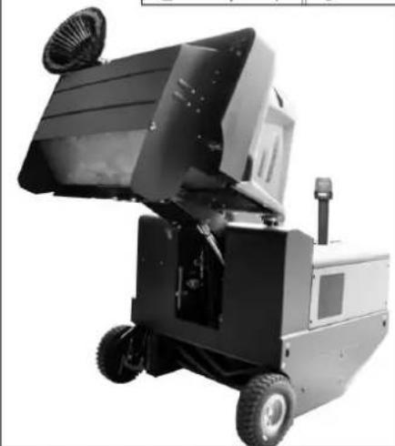
Unloading tips
△DANGER
Risk of personal injury or damage!
Observe the weight of the appliance when you load it!
Do not use a fork lift, the appliance could get damaged.
| Unladen weight (without attachment sets) | 920 kg* |
| * If upgrade kits are installed, the weight is respectively higher. | |
Use a suitable ramp or a crane to load the appliance!
Observe when using a ramp: Ground clearance 70~mm
Operating and Functional Elements

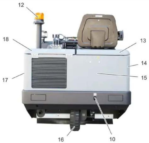

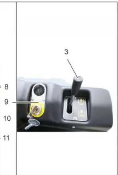
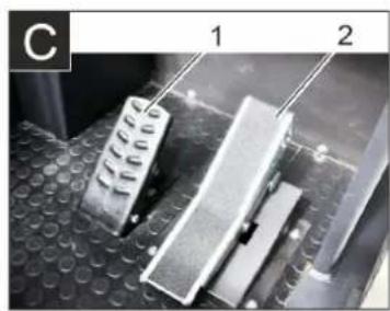
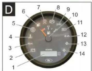
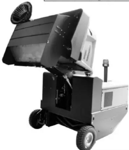
Illustration of sweeper
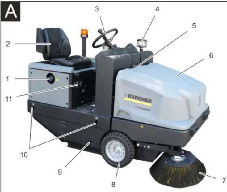
Illustration A
1 Tank lid
2 Seat (with seat contact switch)
3 Steering wheel
4 Centrifugal separator
5 Lock of appliance hood
6 Cover
7 Side brush, right
8 Front wheel
9 Roller brush access
10 Lashing point
11 Nameplate
12 Beacon lamp
13 Appliance cover right side
14 Cover, right
15 Tail panel
16 Rear wheel
17 Cover, left
18 Bonnet left side (engine bonnet)
Optional features
| Overhead guard 2.851-691 | 0 |
| Working light 2.851-279.0 | |
| Side brush, left 2.851-272.0 |
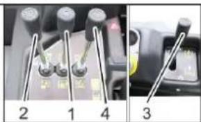
Operating field Pedals
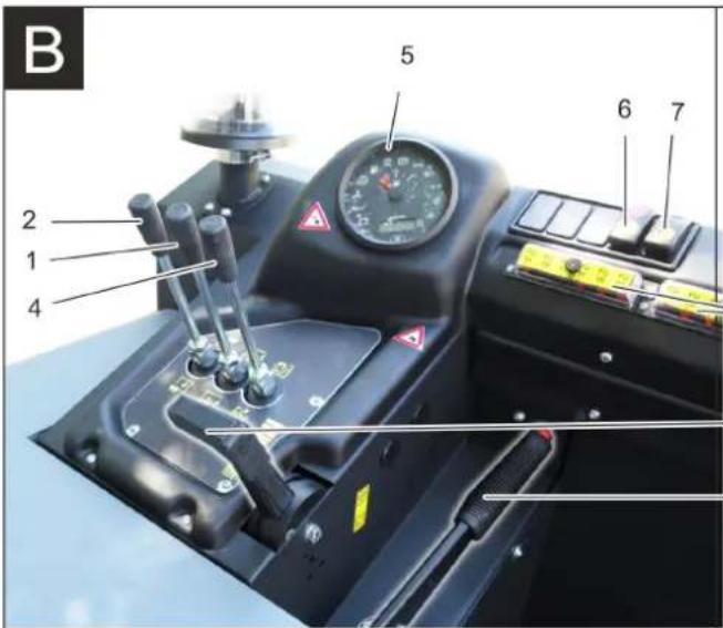
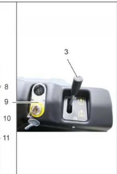
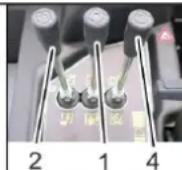
Illustration 3
1 Control lever
Raising/lowering the roller brush
2 Control lever
Raise/ lower waste container
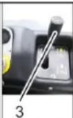
3 Control lever
Raising/lowering the side brush
4 Control lever
Open/close container lid
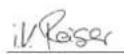
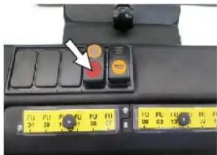
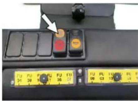
5 Indicator lamps and display
6 Switch blower and filter cleaning Position centred: Filter cleaning and blower off Rear position: Blower on Front position: Filter cleaning on
7 Horn switch
8 Fuses
9 Ignition lock Filament symbol:Pre-heat Position 0:Switch off engine
Position 1: Ignition on
Position 2: Start the engine
10 Motor speed adjustment Gas lever
11 Parking brake
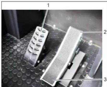
Illustration
1 Brake pedal
2 Accelerator pedal forward / reverse
Indicator lamps and display
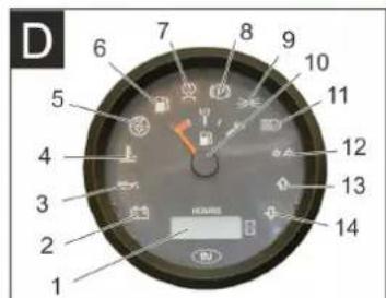
Illustration
1 Operating hour counter
2 Charge warning lamp
3 Oil pressure warning lamp
4 Cooling water temperature warning lamp
5 Motor suction air
6 Warning lamp fuel reserve
7 Preglow indicator light
8 Indicator lamp (not connected)
9 Indicator light parking light/low beam (option)
10 Tank indicator
11 Without function, only illuminates during start-up of the motor (self-test)
12 Without function
13 Without function
14 Without function
Before Startup
Lock/ release parking brake
Loosen parking brake; press brake pedal at the same time.
Activate the parking brake; press brake pedal at the same time.
Moving sweeper without engaging self-propulsion
1 Position of the freewheel lever up - appliance can be pushed.
Open engine cover.
Turn the freewheel lever (red) to the top position.
ATTENTION
Do not move the machine for long distances without engaging self-propulsion; a speed of 10km / h should not be exceeded.
Return the freewheel lever into its original position.
Moving sweeper by engaging selfpropulsion
1 Position freewheel lever down - appliance is ready to start.
Turn back the freewheel of the hydraulic pump in a clockwise direction up to the stop after moving the machine.
Start up
General notes
Read the operating instructions of the engine manufacturer before start-up and follow the safety instructions carefully.
Park the sweeper on an even surface.
Remove ignition key.
Lockparkingbrake.
Inspection and maintenance work
Daily before starting operations
Check fill level of fuel tank.
Check engine oil level.
Check the filling level in the coolant expansion tank.
Check the sweeping roller and the side brush for wear and wrapped belts.
Check the wheels for tied up belts.
Check the centrifugal separator and the air filter, clean if required.
Check function of all operator control elements.
Check appliance for damages.
Clean the dust filter with the filter cleaning button.
Note: For description, see section on Care and maintenance.
Refuelling
△DANGER
Risk of explosion!
Only use the fuels specified in the Operations Manual.
Do not refuel the machine in enclosed spaces.
Smoking and naked flames are strictly prohibited.
Ensure that no fuel reaches the hot open surfaces.
Check fuel level via the tank indicator.
Switch off engine.
Open fuel filler cap.
Fill in diesel.
Wipe off any spilt fuel and close fuel filler cap.
Operation
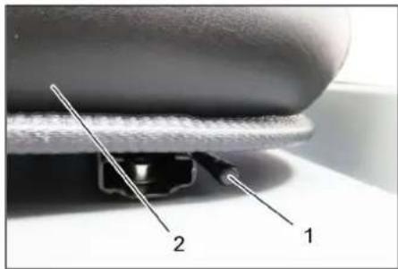
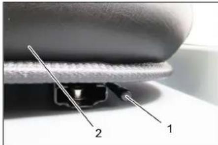
Adjusting driver's seat
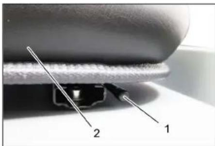
1 Lever for seat adjustment
2 Driver seat
Pull seat adjustment lever outwards.
Slide seat, release lever and lock in place.
Check that the seat is properly locked in position by attempting to move it backwards and forwards.
Starting the machine
Note: The machine is equipped with a seat contact switch If the driver's seat is vacated, the machine is switched off.

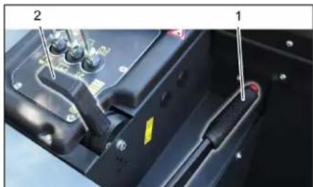
1 Parking brake
2 Motor speed adjustment
Sit on the driver's seat.
Lockparking brake.
Engine speed adjustment - push forward by 1/3.
Pre-heat
Insert the ignition key into the ignition switch.
Turn the ignition key to position "Filament".
Pre-heat lamp glows.
Start the engine
Press the brake pedal in order to start the engine.
When the pre-heating lamp goes off, turn the ignition key to position "I".
If the machine starts, release the ignition key.
Note: Never operate the starter motor for longer than 10 seconds. Wait at least 10 seconds before operating the starter motor again.
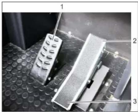
Drive the machine
1 Brake pedal
2 Accelerator pedal, "forwards"
3 Accelerator pedal, "reverse"
Push the motor speed adjustment all the way to the front (operating speed).
Press brake pedal and keep it depressed.
Releaseparkingbrake.
Drive forward
Press slowly the accelerator pedal "forward".
Reverse drive
△DANGER
Risk of injury!
When reversing, there must not be any risk for third parties, have somebody marshal the driver if necessary.
Press slowly the accelerator pedal "reverse".
Driving method
The accelerator pedal can be used to vary the driving speed infinitely.
Avoid sudden operation of the pedal as this may damage the hydraulic system.
In the event of power loss on inclined surfaces, slightly reduce the pressure on the accelerator pedal.
Brakes
Release the accelerator pedal, the machine brakes automatically and stops.
Note: The braking effect can be supported by pressing the brake pedal.
Driving over obstacles
Driving over fixed obstacles which are 70 mm high or less:
Drive forwards slowly and carefully. Driving over fixed obstacles which are more than 70~mm high:
Only drive over these obstacles using a suitable ramp.
Sweeping mode
ATTENTION
Do not sweep up packing strips, wire or similar objects as this may damage the sweeping mechanism.
Note: To achieve an optimum cleaning result, the driving speed should be adjusted to take specific situations into account.
Note: During operation, the dust filter should be shaken off and cleaned at regular intervals.
Note: When frequently working in areas with fine dust, the filter must be cleaned more often.
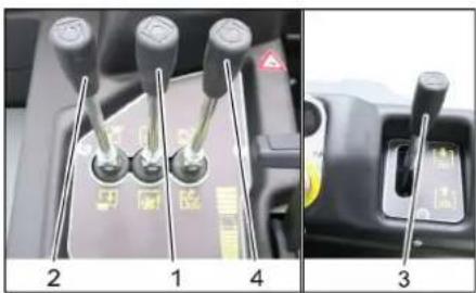
Control lever
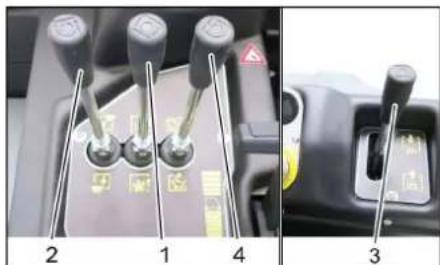
1 Control lever roller brush
2 Control lever waste container
3 Control lever side brush
4 Control lever container flap
Control lever roller brush
Control lever roller brush (1) to the front: Roller brush is lowered.
Control lever roller brush (1) to the back: Roller brush rises.
Control lever waste container
Control lever waste container (2) to the front; Waste container is lowered.
Control lever waste container (2) to the back: Waste container is raised.
Control lever side brush
Control lever side brush (3) to the front: Side brush is lowered.
Control lever side brush (3) to the back: Side brush is raised.
Control lever container flap
Control lever container flap (4) to the front: The container flap of the waste container opens.
Control lever container flap (4) to the back: The container flap of the waste container closes.
Sweeping dry floors

Switch on the blower.
With surface cleaning: Control lever roller brush (1) to the front: Roller brush is lowered.
Control lever container flap (4) to the front: Container flap opens.
With cleaning of side edges: Control lever side brush (3) to the front: Side brush is lowered.
Sweeping damp or wet floors
Switch off the blower.
With surface cleaning: Control lever roller brush (1) to the front: Roller brush is lowered.
Control lever container flap (4) to the front: Container flap opens.
With cleaning of side edges: Control lever side brush (3) to the front: Side brush is lowered.
Emptying waste container
△DANGER
Risk of injury!
During the emptying process, persons and animals must not stay within the swivelling range of the waste container.
Danger of tipping!
Place the device on an even surface during the emptying process.
WARNING
Risk of crushing!
Never reach into the rod assembly for the drainage mechanism. Do not stay under the raised container.
ATTENTION
Risk of personal injury or damage!
Material of the rotating roller brush may be catapulted off during the emptying process. Keep an appropriate distance.
Raise the roller brush and side brush by means of the control levers, in order to do so, pull the control levers (1 and 3) to the back.
Close the container flap, in order to do so, move the control lever (4) to the back:
Raise the container flap, in order to do so, move the waste container control lever (2) to the back:
Slowly drive towards the collection container.
Lockparkingbrake.
Open the container flap, in order to do so, push the container flap operating lever (4) to the front and empty the waste container.
Close the container flap, in order to do so, push the container flap operating lever (4) to the back until it is tipped inwards in the end position.
Releaseparkingbrake.
Drive away the collection container slowly.
Lower the waste container into the end position, in order to do so, move the waste container control lever (2) to the front
Turn off the appliance
Raise the roller brush and side brush by means of the control levers, in order to do so, pull the control levers (1 and 3) to the back.
Close the container flap, in order to do so, move the control lever (4) to the back:
Pull the motor speed adjustment all the way to the back.
Press brake pedal and keep it depressed.
Lockparking brake.
Turn ignition key to "0" and remove it.
Transport
△DANGER
Transport damage!
Observe the net weight (transport weight) of the device during transport on trailers or vehicles.
When transporting in vehicles, secure the appliance according to the guidelines from slipping and tipping over.
Turn ignition key to "0" and remove it.
Lockparkingbrake.
Secure the appliance at the lashing points (4x) using tension belts, ropes or chains.
Secure the wheels of the machine with wheel chocks.
Disconnect the battery of the sweeper during transport.
Storage/decommissioning
Park the sweeper on a level surface in a dry, frost protected area. Protect it against dust by means of covering material.
Raise the roller brush and the sidebrushes to prevent the bristles from being damaged.
Close the container flap.
Turn ignition key to "0" and remove it.
Lockparkingbrake.
Lock the sweeper to ensure that it does not roll off.
Additionally observe the following points if the sweeper is not used over a longer period of time:
Change engine oil.
Drain off the cooling water if frost is expected and check whether there is adequate anti-frosting agent.
Clean the inside and outside of the sweeper.
Disconnect battery.
Charge battery and recharge it approx. every 2 months.
Care and maintenance
General notes
ATTENTION
Risk of damage!
Do not rinse out the dust filter.
Maintenance work may only be carried out by approved customer service outlets or experts in this field who are familiar with the respective safety regulations.
Mobile appliances used for commercial purposes are subject to safety inspections according to VDE 0701.
Park the sweeper on an even surface.
Turn ignition key to "0" and remove it.
Lockparkingbrake.
Cleaning
CAUTION
Risk of damage!
Do not clean the appliance with a water hose or high-pressure water jet (danger of short circuits or other damage).
Cleaning the inside of the machine DANGER
Risk of injury!
Wear dust mask and protective goggles.
Clean machine with a cloth.
Blow through machine with compressed air.
External cleaning of the appliance
Clean the machine with a damp cloth which has been soaked in mild detergent.
Note: Do not use aggressive cleaning agents.
Maintenance intervals
Note: The elapsed-time counter shows the timing of the maintenance intervals.
Maintenance by the customer
Note: Where maintenance is carried out by the customer, all service and maintenance work must be undertaken by a qualified specialist. If required, a specialised Kärcher dealer may be contacted at any time.
Daily maintenance:
Check fill level of fuel tank.
Check engine oil level.
Check the filling level in the coolant expansion tank.
Check the sweeping roller and the side brush for wear and wrapped belts.
Check fuel filter.
Check the centrifugal separator and the air filter, clean if required.
Check function of all operator control elements.
Check appliance for damages.
Weekly maintenance:
Clean the water cooler.
Clean the hydraulic oil cooler.
Check hydraulic unit.
Check the hydraulic oil level.
Check brake fluid status.
Check the pad for wear, replace if required.
Check the container lid and lubricate it.
Maintenance to be carried out every 50 operating hours:
Drain the water from the diesel/water separator.
Maintenance following wear:
Replace sealing strips.
Readjust the side seals or replace them.
Replace roller brush.
Replace side brush.
Note: For description, see section on Maintenance work.
Maintenance by Customer Service
Note: In order to safeguard warranty claims, all service and maintenance work during the warranty period must be carried out by the authorised Kärcher Customer Service in accordance with the maintenance booklet.
Maintenance to be carried out after 50 operating hours:
Have the first maintenance performed by the customer service in accordance with the inspection check list.
Maintenance after 250/500/1000/1500/ 2000 operating hours:
Have the maintenance performed by the customer service in accordance with the inspection check list.
Maintenance Works
Preparation:
Park the sweeper on an even surface.
Turn ignition key to "0" and remove it.
Lockparkingbrake.
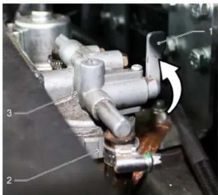
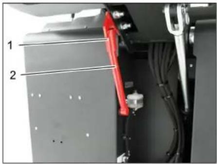
General notes on safety
△DANGER
Risk of injury!
Always apply the safety rod when the waste container is raised.
Perform the safeguarding only from outside the hazard zone.
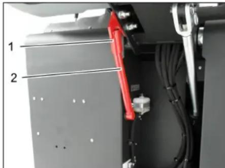
1 Holder of safety rod
2 Safety rod
Fold the safety rod for the high emptying up and insert it into the holder (secured).

Please do not release engine oil, fuel oil, diesel and petrol into the environment. Protect the ground and dispose of used oil in an environmentally-clean manner.
Safety notes regarding the batteries
Please observe the following warning notes when handling batteries:
| Observe the directions on the battery, in the instructions for use and in the vehicle operat-ing instructions! |
| Wear an eye shield! |
| Keep away children from acid and batteries! |
| Risk of explosion! |
| Fire, sparks, open light, and smoking not allowed! |
| Danger of causticization! |
| First aid! |
| Warning note! |
| Disposal! |
| Do not throw the battery in the dustbin! |
DANGER
Risk of explosion!
Only use batteries with terminal cover. Restore terminal cover in the event of loss.
△DANGER
Risk of explosion!
Do not place tools or similar items on the battery. Risk of short-circuit and explosion.
△DANGER
Risk of injury!
Ensure that wounds never come into contact with lead. Always clean your hands after working on batteries.
△DANGER
Risk of fire and explosion!
Smoking and naked flames are strictly prohibited.
Rooms where batteries are charged must have good ventilation because highly explosive gas is emitted during charging.
DANGER
Danger of causticization!
Rinse thoroughly with lots of clear water if acid gets into the eye or comes in contact with the skin.
Then consult a doctor immediately.
Wash off the acid If it comes in contact with the clothes.
Installing and connecting the battery
Normally, the machine is equipped with a maintenance-free battery.
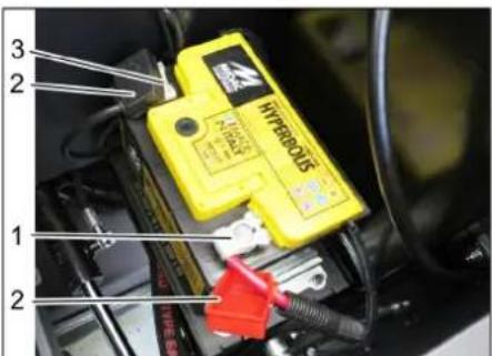
1 Positive terminal
2 Terminal cover
3 Negative terminal
Insert battery in battery mount.
Screw on mounts on battery base.
Connect pole terminal (red cable) to positive pole (+).
Connect pole terminal to negative pole (-).
Attach the pole covers.
Check that the battery poles and pole terminals are adequately protected with pole grease.
Check and correct the fluid level of the battery (only with low-maintenance battery with cell caps)
CAUTION
Risk of damage!
Regularly check the fluid level in acid-filled batteries.
Unscrew all cell caps.
Take a sample from each cell using the acid tester.
The acid in a fully charged battery has a specific weight of 1.28kg / l at a temperature of 20^
The acid in a partially discharged battery has a specific weight between 1.00 and 1.28kg / l
The specific weight of the acid must be uniform in all cells.
Put the acid sample back into the same cell.
Where fluid level is too low, top up cells to the mark provided with distilled water.
Charge battery.
Screw in cell caps.
Charging battery
△DANGER
Risk of injury!
Comply with safety regulations on the handling of batteries. Observe the directions provided by the manufacturer of the charger.
△DANGER
Risk of damage!
Charge the battery only with an appropriate charger.
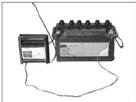
Unscrew all cell caps. (only with low-maintenance battery)
Connect positive terminal cable from the charger to the positive pole connection on the battery.
Connect negative terminal cable from the charger to the negative pole connection on the battery.
Plug in mains connector and switch on charger.
Charge battery using lowest possible level of charging current.
When the battery is charged, first remove the charger from the mains and then disconnect it from the battery.
Screw in cell caps. (only with low-maintenance battery)
Remove the battery
Disconnect pole terminal to negative pole (-).
Disconnect pole terminal to positive pole (+)
Loosen the mounts on battery base.
Remove the battery from the battery holder.
Dispose of the used battery according to the local provisions.
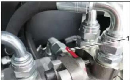
Checking the brake fluid level and topping up brake fluid
△DANGER
Risk of injury!
Always apply the safety rod when the waste container is raised.
Perform the safeguarding only from outside the hazard zone.
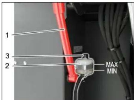
1 Holder of safety rod
2 Brake fluid container
3 Closing head
Move up the waste container and secure it by means of the safety rod, see Chapter "Emptying the waste container"
Check if the there is enough brake fluid in the brake fluid reservoir.
Note
The filling level has to be between Min. and Max.
If necessary, refill DOT brake fluid currently commercially available.
Check engine oil level and top up, if required
△DANGER
Risk of burns!
Allow engine to cool down.
Wait for at least 5 minutes after switching off the engine before checking the engine oil fill level.
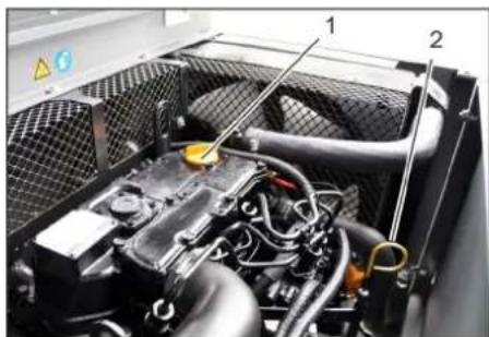
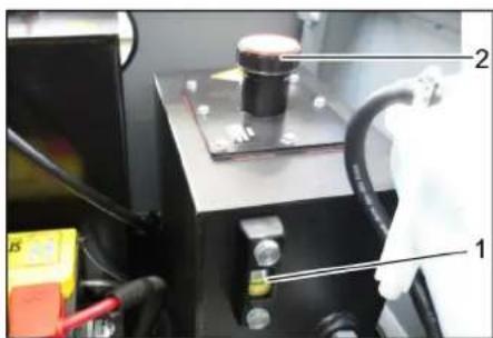
1 Oil cap (engine)
2 Oil dipstick
Pull out oil dipstick.
Wipe off oil dipstick and insert.
Pull out oil dipstick.
Read the value of the oil level.
Insert the oil dip again.
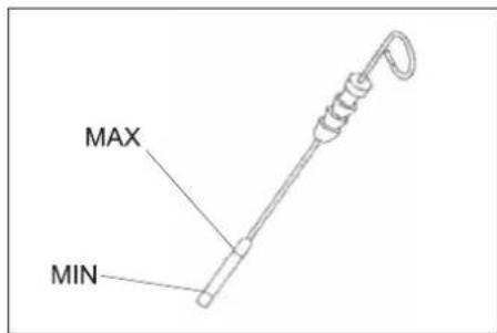
- The oil level must lie between "MIN" and "MAX" marking.
- Add motor oil if the oil level is below the "MIN" marking.
- Do not fill oil above the "MAX" marking.
Remove oil cap.
Fill in motor oil. For oil type refer to Chapter "Technical specifications".
Close oil cap.
Wait at least 5 minutes.
Check engine oil level.
Change the motor oil and the oil filter CAUTION
Risk of burns due to hot engine oil!
Allow engine to cool down.
Prepare a collection container for at least 6 litres of engine oil.
Allow engine to cool down.

Unscrew oil drain plug.
Remove oil cap.
Drain off oil.
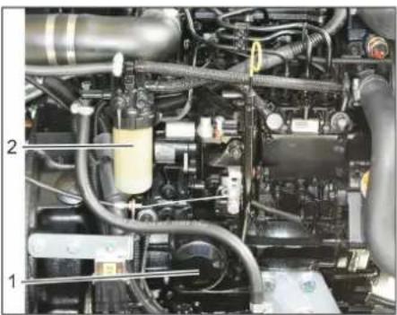
1 Engine oil filter
2 Fuel filter
Unscrew the oil filter.
Clean the intake and sealing areas.
Coat the washer of the new oil filter with oil before fitting it.
Fit in the new oil filter and tighten it by hand.
Screw in the oil drain screw along with the new washer. Tightening torque: 25 Nm
Fill in motor oil. For oil type and filling quantity refer to Chapter "Technical specifications".
Close oil cap.
Let the motor run for approx. 10 seconds.
Check engine oil level.
Check fuel filter
Check the fuel filter for soiling.
Clean the fuel filter and filter casing as needed; replace the fuel filter if necessary.
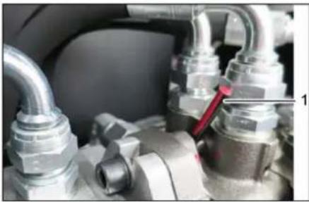
Replace the fuel filter
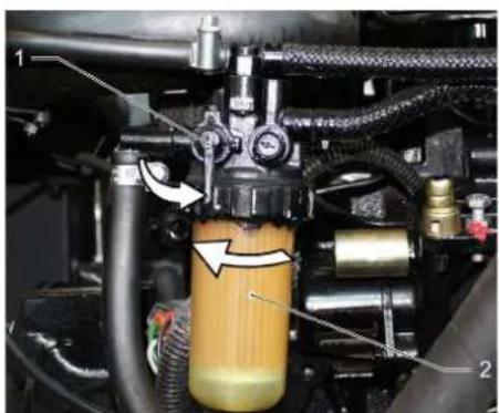
1 Fuel cock
2 Fuel filter
Close fuel cock.
Unscrew the fuel filter and replace it.
1 Fuel cock
2 Fuel filter
NOTICE
Fill the fuel filter with diesel fuel prior to installing it.
Screw the new fuel filter in.
Torque the fuel filter to 20~Nm
Open fuel cock
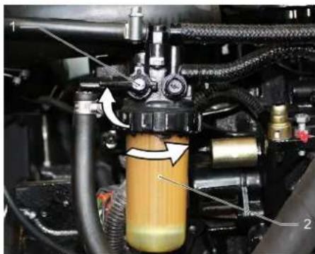
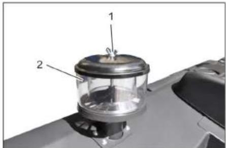
Draining the condensation water from the diesel water separator
1 Fuel cock
2 Separator cup
3 Water separator
Close fuel cock.
Unscrew the separator cup and empty it.
Screw on the separator cup.
Open fuel cock
Check hydraulic oil level and refill hydraulic oil
NOTICE
The waste container must not be raised.
Open engine cover.
1 Hydraulic oil sight glass
2 Screw cap, oil fill opening
Check hydraulic oil level in the looking glass.
- The oil level must lie between "MIN" and "MAX" marking.
- Add hydraulic oil if the oil level is below the "MIN" marking.
Loosen the closing cap of the oil filling opening.
Clean the filling area.
Refill hydraulic oil. For oil type refer to Chapter "Technical specifications".
Replace and tighten the closing cap of the oil filling opening.
Check hydraulic unit
NOTICE
Only Kärcher Customer Service is authorised to carry out maintenance tasks on the hydraulic unit.
Lockparkingbrake.
Start the motor.
Check all hydraulic hoses and connections and ensure that they are leak-proof.
Check coolant level
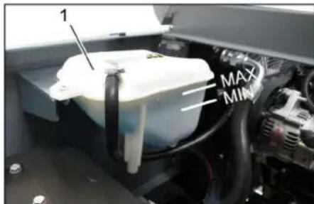
1 Coolant expansion tank
Check filling level while the motor is cold.
Check the filling level in the coolant expansion tank. The correct coolant level has to be between MIN and MAX.
Checking and cleaning water/hydraulic oil cooler
△DANGER
Risk of burning and scalding!
Allow the water cooler to cool down for at least 20 minutes.
The coolant level of the water cooler is checked at the coolant expansion tank. See chapter "Checking the cooling water level".
Clean cooler lamella. Remove soiling by means of a soft brush, compressed air or low water pressure.
Check cooler hoses and connections and ensure that they are leak-proof.
Clean the fan.
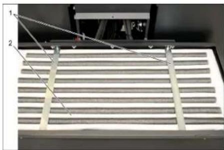
Checking roller brush
Start the motor.
Raise the waste container up to the end-position.
Switch off engine.
Lockparkingbrake.
Use the safety bar for emptying from a height.
Remove belts or cords from roller brush.
Remove the safety bar.
Start the motor.
Lower the waste container up to the end-position.
Switch off engine.
Replacing roller brush
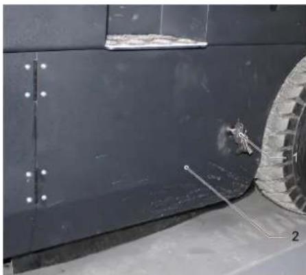
1 Key
2 Side panels
Drive the waste container up and support it with the safety rod.
Open the side covers using a key.
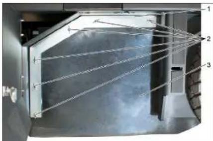
1 Holding bow
2 Wing nut
3 Side seal
Unscrew the wing nuts.
Remove the retaining clamp.
Unscrew the wingnuts from the holding plate side seals and remove the holding plate.
Flip the side seal out.
Uncscrew the retaining screw of the roller brush intake, and swing the intake to the outside.
Pull out roller brush.
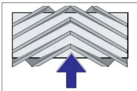
Installation position of roller brush in direction of travel (top view)
Note: When installing the new roller brush, ensure correct positioning of the bristle assembly.
Install new roller brush. The nuts of the roller brush must be inserted on the notches of the opposite crank.
Note: Once the new roller brush has been installed, the sweeping track must readjusted.
Check and adjust roller brush sweeping track
Switch off suction blower.
Drive sweeper on to a smooth, even surface covered with a visible layer of dust or chalk.
Lower the roller brush by means of the control lever and let it run (approx. 10 s).
Raise roller brush.
Drive machine backwards.
Check sweeping mirror.
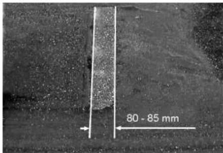
The sweeping track should have an even rectangular shape which is 80 - 85mm wide. Adjusting the sweeping level
1 Spring
2 Rating nut
3 Locknut
4 Threaded rod
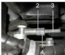
Adjust the sweeping track position by adjusting the adjustment screw.
Check sweeping mirror.
Check and adjust sweeping track of the side-brush
The side-brushes lift up.
Drive sweeper on to a smooth, even surface covered with a visible layer of dust or chalk.
Lower the side brushes using the control lever and allow them to run for approx. 10 seconds.
The side-brushes lift up.
Drive machine backwards.
Check sweeping mirror.
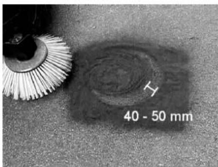
The width of the sweeping track should lie between 40-50 mm.
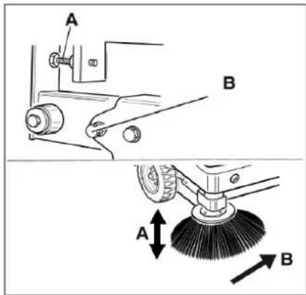
Set the sweeping track using the two adjusting screws.
Check sweeping mirror.
Adjust the side seals
△DANGER
Risk of injury!
Always apply the safety rod when the waste container is raised.
Perform the safeguarding only from outside the hazard zone.
Drive the waste container up and secure it with the safety rod.
Fold the safety rod for the high emptying up and insert it into the holder (se-cured).

1 Holder of safety rod
2 Safety rod
Open the side cover as described in Chapter "Replace brush roller".
Release the 6 wing nuts on the side holding plate.
Loosen 3 nuts (SW 13) on the front holding plate.
Press the side seal down (elongated hole) until it is about 1 to 3mm to the floor.
Screw in the holding plates.
Repeat the procedure on the other side of the appliance.
Manually clean the dust filter

Switch on manual filter shake off.
Check/replace dust filter
WARNING
Risk of injury!
Wear a dust mask when working around the dust filter. Observe safety regulations on the handling of fine particles.
Clean the dust filter with the filter cleaning button.
Empty waste container.
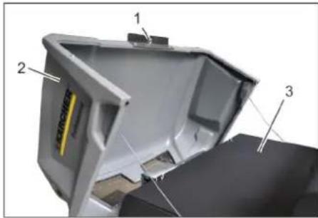
1 Lock of appliance hood
2 Cover
3 Filter cover
Open the lock, remove the star grip screw to do this.
Fold cover forwards.
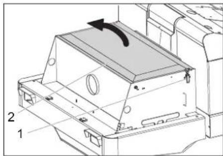
1 Lock, filter cover (2x)
2 Filter cover
Open the lock.
Open filter cap.
1 Cross struts
2 Dust filter
Check the dust filter, clean or replace if necessary.
Note
The dust filter may only be replaced by Karcher Customer Service.
Insert and lock the filter cover.
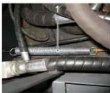
Check and adjust the V-Belt
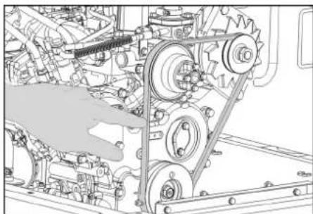
The V-Belt must deflect approx. 7-9 mm at a pressure of 10kg
Get the V-belt tension adjusted by an authorized customer service.
Check air filter and replace, if necessary
1 Lock
2 Air filter housing
Remove side panel.
Remove the air filter housing.
Replace the air filter insert.
Note: Installation position with blowout opening pointing down (see illustration).
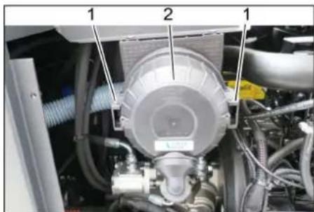
Clean the centrifugal separator
1 Wing nut
2 Centrifugal separator
Unscrew the wing nut from the centrifugal separator.
Clean the centrifugal separator.
Replacing fuses
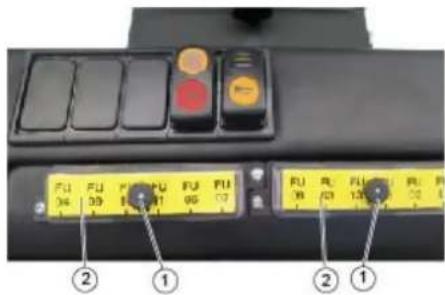
1 Lock nut
2 Cover fuse box
Unscrew the knurled nut.
Open the cover on the fuse box.
Check the fuses.
Replace defective fuses.
Note: Only use fuses with identical safety ratings.
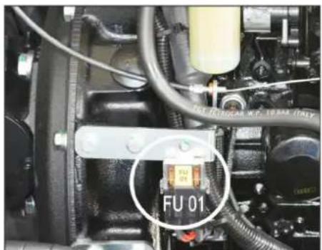
Note: The fuse FU 01 is located in the engine compartment.
| FU 01 Main fuse 60 A | |
| FU 02 Horn Hydraulic oil cooler | 20 A |
| FU 03 Safety relay Multifunction display | 10 A |
| FU 04 Beacon lamp 5 A | |
| FU 05 Safety relay Time delay | 25 A |
| FU 06 Cabin lighting Wiper | 10 A |
| FU 07 Fuel pump 10 A | |
| FU 08 Time relay Seat contact switch | 3 A |
| FU 09 Left lighting 7,5 A | |
| FU 10 Right lighting 7,5 A | |
| FU 11 Front work lights (low beam) | 10 A |
| FU 12 Vibrator system 20 A | |
| FU 13 Backup signal 5 A |
| Troubleshooting | |
| Fault Remedy | |
| Appliance cannot be started Sit on | the driver seat, the seat contact switch gets activated. |
| Press the brake pedal in order to start the engine. | |
| Charging or replacing battery | |
| Fill in fuel,deaerate the fuel system | |
| Change fuel filter | |
| Check fuel pipes,connections and joints and maintain them if required | |
| Inform Kärcher Customer Service. | |
| Engine is running erratically Clean | air filter or change filter cartridge. |
| Check fuel pipes,connections and joints and maintain them if required | |
| Inform Kärcher Customer Service. | |
| Engine is overheated Refill coolant | |
| Rinse cooler | |
| Tighten V-Belt | |
| Inform Kärcher Customer Service. | |
| Engine is running but machine is only moving slowly or is not moving at all | Release parking brake |
| Move the gas lever all the way to the front (high speed). | |
| Check for trapped ribbons and strings. | |
| Inform Kärcher Customer Service. | |
| Whistling sound in the hydraulic system | Refill hydraulic fluid |
| Inform Kärcher Customer Service. | |
| Brushes are rotating slowly or not at all | Move the gas lever all the way to the front (high speed). |
| Check for trapped ribbons and strings. | |
| Inform Kärcher Customer Service. | |
| Too little or no suction power in the brush area | Check dust filter,clean or replace. |
| Inform Kärcher Customer Service. | |
| Dust gathers in the machine Adjust | the side seals |
| Switch on blower | |
| Check dust filter,clean or replace. | |
| Replace filter washers | |
| Open the container flap of the waste container. | |
| Inform Kärcher Customer Service. | |
| Sweeping unit does not pick up waste | Empty waste container |
| Check dust filter,clean or replace. | |
| Replacing roller brush | |
| Adjust sweeping track | |
| Replace sealing strips of the waste container | |
| Remove the blocking of the brush roller | |
| Open the container flap of the waste container. | |
| Inform Kärcher Customer Service. | |
| Waste container does not raise or lower | Move the gas lever all the way to the front (high speed). |
| Inform Kärcher Customer Service. | |
| The container flap of the waste container does not open. | Inform Kärcher Customer Service. |
| Operation problems with hydraulic movement parts | Inform Kärcher Customer Service. |
| Technical specifications | ||
| KM 130/300 R D Classic | ||
| Machine data | ||
| Drive speed, forward km/h 10 | ||
| Drive speed, reverse km/h 10 | ||
| Climbing capability (max.) % 18 | ||
| Surface cleaning performance without side brushes m | 2/h 10000 | |
| Surface output with side-brush m | 2/h 13000 | |
| Working width without side brushes mm 1000 | ||
| Working width with side-brush mm 1300 | ||
| Protection type, drip-proof -- IPX 3 | ||
| Usage duration when tank is full h 4 | ||
| Engine | ||
| Type -- YANMAR 3TNV76A | ||
| Type -- 3-Cylinder 4-stroke diesel engine | ||
| CO2Emission according to the measurement procedure of EU regulation 2016 1628 (level V) | g/kWh | 932,0 |
| Cooling type | -- Water cooling | |
| Rotation direction | -- Anticlockwise direction | |
| Holes | mm 70 | |
| Hub | mm 82 | |
| Cylinder capacity | cm³ | 1116 |
| Amount of oil | l | 3,5 |
| Operating speed | 1/min | 2500 |
| Max. speed | 1/min | 2500 |
| Dry run speed | 1/min | 1300 |
| Max. power | kW/PS | 15,8 / 21,5 |
| Maximum torque at 2100 rpm | Nm | 67,9 |
| Oil filter | -- Filter cartridge | |
| Suction air filter | -- Internal filter cartridge, external filter car-tridge | |
| Fuel filter | -- Filter cartridge | |
| Electrical system | ||
| Battery | V, Ah | 12, 60 |
| Generator, rotary current | V, A | 12, 55 |
| Starter | -- Electrical starter | |
| Hydraulic system | ||
| Oil quantity in the entire hydraulic system | l | 26,5 |
| Oil quantity in hydraulic tank | l | 21,2 |
| Oil grades | ||
| Engine (above 25 °C) | -- SAE 30, SAE 10W-30, SAE 15W-40 | |
| Engine (0 to 25 °C) | -- SAE 20, SAE 10W-30, SAE 10W-40 | |
| Engine (below 0 °C) | -- SAE 10W, SAE 10W-30, SAE 10W-40 | |
| Hydraulics | -- HV 46 | |
| Waste container | ||
| Max. unloading height | mm 1400 | |
| Volume of waste container | l | 300 |
| Roller brush | ||
| Roller brush diameter | mm 300 | |
| Roller brush width | mm 1000 | |
| Speed | 1/min | 350 |
| Sweeping track | mm 80 | |
| Side brushes | ||
| Side brush diameter | mm 600 | |
| Speed (continuous) | 1/min | 0 - 60 |
| Solid rubber tyres | ||
| Size, front | -- 15-4.5x8 | |
| Size, rear | -- 15-4.5x8 | |
| Brake | ||
| KM 130/300 R D Classic | ||
| Front wheels -- mechanical | ||
| Rear wheel -- hydrostatic | ||
| Filter and vacuum system | ||
| Type - Pocket filter | ||
| Speed 1/min 2800 | ||
| Filter surface area, fine dust filter m | 2 | 7,8 |
| Nominal vacuum, suction system mbar 15,5 | ||
| Nominal volume flow, suction system m | 3/h 800 | |
| Vibrator system -- Electric motor | ||
| Working conditions | ||
| Temperature °C -5 and +40 | ||
| Air humidity, non-condensing % 0 - 90 | ||
| Values determined as per EN 60335-2-72 | ||
| Noise emission | ||
| Sound pressure level LpA | dB(A) | 80 |
| Uncertainty KpA | dB(A) | 3 |
| Sound power level LwA + Uncertainty KwA | dB(A) | 98 |
| Machine vibrations | ||
| Hand-arm vibration value | m/s2 | <2,5 |
| Seat | m/s2 | 0,7 |
| Uncertainty K | m/s2 | 0,1 |
| Dimensions and weights | ||
| Length x width x height | mm | 2040x1330x1430 |
| Right turning radius | mm | 1400 |
| Left turning radius | mm | 1400 |
| Unladen weight | kg | 920 |
| Permissible overall weight | kg | 1397 |
| Permissible front axle load | kg | 862 |
| Permissible rear axle load | kg | 535 |
| Capacity of fuel tank, diesel | l | 16 |
| Subject to technical modifications! | ||
EU Declaration of Conformity
We hereby declare that the machine described below complies with the relevant basic safety and health requirements of the EU Directives, both in its basic design and construction as well as in the version put into circulation by us. This declaration shall cease to be valid if the machine is modified without our prior approval.
Product: Ride-on vacuum sweeper
Type: KM 130/300 R D Classic
1.186-139
Relevant EU Directives
2006/42/EC (+2009/127/EC)
2014/30/EU
2000/14/EC
Applied harmonized standards
EN 60335-1
EN 55012: 2007 + A1: 2009
EN 55014-2: 2015
Applied national standards
Applied conformity evaluation method
2000/14/EC: Appendix V
Sound power level dB(A)
Measured: 96
Guaranteed: 98
The signatories act on behalf of and with the authority of the company management.


Documentation supervisor:
S. Reiser
Alfred Karcher SE & Co. KG
71364 Winnenden (Germany)
Tel.: +49 7195 14-0
Fax: +49 7195 14-2212
Winnenden, 2020/01/01
Consignes generales. FR 1
www.kaercher.com/REACH
Garantie
71364 Winnenden (Germany)
Tel.: +49 7195 14-0
Fax: +49 7195 14-2212
Winnenden, 2020/01/01
2006/42/CE (+2009/127/CE)
2014/30/UE
2000/14/CE
71364 Winnenden (Germany)
Tel.: +49 7195 14-0
Fax: +49 7195 14-2212
Winnenden, 2020/01/01

Chairman of the Board of Management
Director Regulatory Affairs & Certification
www.kaercher.com/REACH
Garantie
H.Jenner Chairman of the Board of Management

S. Reiser
Director Regulatory Affairs & Certification
71364 Winnenden (Germany)
Tel.: +49 7195 14-0
Fax: +49 7195 14-2212
Winnenden, 2020/01/01
www.kaercher.com/REACH
Garantia
2006/42/CE (+2009/127/CE)
2014/30/UE
2000/14/CE
71364 Winnenden (Germany)
Tel.: +49 7195 14-0
Fax: +49 7195 14-2212
Winnenden, 2020/01/01

Chairman of the Board of Management

S. Reiser
Director Regulatory Affairs & Certification
Responsible de documento:
www.kaercher.com/REACH
Garantia
Ajustar o assento do conductor
1 Alavanca de ajuste do assento
2 Banco do conductor
Alavanca de commando da vassoura later
→ Alavanca de commando da vassoura lateral (3) para arente: Vassoura lateral desce.
→ Alavanca de commando da vassoura lateral (3) para tras: Vassoura lateral levanta.
Alavanca de commande da tampa do recipiente
2006/42/CE (+2009/127/CE)
2014/30/UE
2000/14/CE
71364 Winnenden (Germany)
Tel.: +49 7195 14-0
Fax: +49 7195 14-2212
Winnenden, 2020/01/01

Chairman of the Board of Management
Director Regulatory Affairs & Certification
www.kaercher.com/REACH
Garanti
I de enkelte lande gelder de af vore forhandlere fastlagte garantibetingelser.
2006/42/EF (+2009/127/EF)
2014/30/EU
2000/14/EF

Chairman of the Board of Management

S. Reiser
Director Regulatory Affairs & Certification
71364 Winnenden (Germany)
Tel.: +49 7195 14-0
Fax: +49 7195 14-2212
Winnenden, 2020/01/01
Generelle merknader.. NO 1
Miljøvern .NO 1
Garanti . NO 1
www.kaercher.com/REACH
Garanti
Anvisining for avlossing
△FARE
1 Oljse-glass,hydraulikkolje
2 Lokk, oljepafyllingsapning
Kontroller hydraulikkoljenivæt i se-glasset.
-Oljenivaaet ma ligge mellom "MIN"-og "MAX"-markeringen.
Dersom oljenivaret under "MIN" markeringen,etterfyll hydraulikkolje.
→ Skru ut lokk pa oljefyllingsapningen.
Rengjør fylleområdet.
Fyll pa hydraulikkolje. For oljetyper, se kapittelet Tekniske data.
→ Skru pa lokk pa oljefyllingsapningen.
Kontroller hydraulikkanlegget
MERKNAD
Rengjore stovfilter manuelt
2006/42/EF (+2009/127/EF)
2014/30/EU
2000/14/EF
Anvende overensstemmende normer
EN 60335-1
EN 55012: 2007 + A1: 2009
EN 55014-2: 2015
Director Regulatory Affairs & Certification
Chairman of the Board of Management
71364 Winnenden (Germany)
Tel.: +49 7195 14-0
Fax: +49 7195 14-2212
Winnenden, 2020/01/01
Allmanna hänvisningar . SV 1
Miljöskydd . SV 1
Garanti . SV 1
www.kaercher.com/REACH
Garanti
Manoverspak behllarlucka
Manoverspak behllarlucka (4) framat: Behllarluckan till sopmaterialbehalla- ren oppnar sig.
Manoverspak behallarlucka (4) bakat: Behallarluckan till sopmaterialbehalla- ren stangs.
Sopa pa torrt underlag
Underhall after slitting:

Chairman of the Board of Management

S. Reiser
Director Regulatory Affairs & Certification
Dokumentationsbefullmaktigad:
S. Reiser
Alfred Karcher SE & Co. KG
71364 Winnenden (Germany)
Tel.: +49 7195 14-0
Fax: +49 7195 14-2212
Winnenden, 2020/01/01
Yleisä ohjeita FI 1
www.kaercher.com/REACH
Takuu
1 Jarrupoljin
2 Ajopoljin "eteenpain"
3 Ajopoljin "taaksepain"
Chairman of the Board of Management
S. Reiser Director Regulatory Affairs & Certification
71364 Winnenden (Germany)
Tel.: +49 7195 14-0
Fax: +49 7195 14-2212
Winnenden, 2020/01/01
AToeKeuOa/AnEepyoioiOn EL 7
Φovtida kai ouvtipnσn .EL 7
EviKc UToDeiEIG .EL7
Kaθαρισμός EL 7
Aiaotnata ouvtnpnoEL7
Epyaoie ouvtnpnong..EL8
Avtietwion v .EL
TexviKa xapaktnpiotika. .EL
Anwon Suuopwongtwv EEEL

Pivx npoiotioe Tn ou-OKeun oac via Tpwn popa, dia
baote autec TIG TTPOTUTTE OBNYIEs XPHON, EVEpynoTe AUPOWVA ME autec KAI KpataTE TIC YIA PEAAOVTKI XPON N YIA TOV ETIOUEVO IIOKNTN.
Tevikéç unodéiEeIc
Av kata tny apaipceon tnc ouakeuaiaic diatniotwoe cnnie TPOPKAnkav kata tn metaopopa, EIDOToinote aoeos tov TPOUNeutn oac.
- OI TPOEIOITIOINTKECS IVAKIOES KAI OI TIVAKIOES UTOBEIEWV TOU EVAI TOTOEETNVECS OTO UNXAVNA, TAPEXOV ONMAVTIKEC UTOBEOISIGYIA TNY AKIDUVN LEITOUPYIA.
-EKTOs aTO TIG UTOOIEEIG OTO EYXEPIO AETOUpyiac TTpeTIE VA AABETe TAPAAAN- LA UTOYN KAI TOUC YEVIKOUC KAVOVIAOUs aopaaEIAc KAI TPoAUNPGS ATUXNmuTAW TOUN TPOBETEIO VOpOHTNS.
PpOraia TepiBaalovToC

www.kaercher.com/REACH
Eyyunon
Apwn uypov n Bpeyevw datt
ATVEPEpyOTIOInOteTovavemuToHpa.
Tia Kaapioe Tpavv MoXaoc Xepiou Kauivopko aipw- 0pu (1) epto: To kauivopko aapw- 0po xanawvei.
Moxxoc xeiipoukattakoi doxeiou (4) Eptpoc: To kattaki tou doxeiou avoiyi.
→ KaTaTovKaThapioo TAAeupikwakpov: MoXaos Xeipiaou TAAeupikou aapowou (3) ePTPO: To TAAeupiko apow-0po xanawvEi.
YI06EiEg: Ia TEPiPyapn, Bλ. KεφαλaiO
Epyaoie oovmpnons.
Uvtnpn an to nvy utnpoeia Eumnpetno n TaeW
YtOBeIg:Pioc diaPuaagTuw EyyunTI Kw aGioaewv, kata T diapkeia Tou xpoVou Eyyunang OeC oEpyaoic eepic Kai ouvtnpang TipeTeVA EKTALoovTai ato Tny EGSouoiobotmevN utnpeia EGUTnPentnOng TEaTow Tc Karcher ouuPwva e To BIIIO ouvtnpang.
Euvtnpnnteia afo 50 wpeaetoupyias:
Aneuuvee ie yia nTv npwn ouvtnpn on oumuovaa Tn Aota eTneewpnoC ony utnpoeia Eutnpentnnc TLa-tuv.
Uvtnpno n eTn a 250/500/1000/ 1500/2000 wpe s Aitoupyiac:
Chairman of the Board of Management
S. Reiser
Director Regulatory Affairs & Certification
YtueBuvoc yypapw Teknpiwns S.Reiser
Alfred Kärcher SE & Co. KG
71364 Winnenden (Germany)
Tel.: +49 7195 14-0
Fax: +49 7195 14-2212
Winnenden, 2020/01/01
Genel bilgiler TR 1
Cevre koruma TR 1
Garanti TR 1
Akesuarlar ve yedek parca
lar. TR 1
www.kaercher.com/REACH
Garanti
Calismaya baslamadan once her gun
Chairman of the Board of Management
Director Regulatory Affairs & Certification
71364 Winnenden (Germany)
Tel.: +49 7195 14-0
Fax: +49 7195 14-2212
Winnenden, 2020/01/01
O6uye yka3aHnra. RU 1
3aunTa okpykaiouei cpeBt RU 1
TapaHTnRU1
PpHaJdJIeXKHOCTN 3aIacHbIe
TeTann RU1
CIMBOBIBpyKOBOIDCTBEIO3K
cnnyataun .RU1
CIMBOJIbHa npnbope..RU1
IcnoB3OBAHnE NO Ha3HaueHnRU 2
YmbiHHeHHe HnpeBnIbHoe
npmeHenne. RU 2
PoiXoJaIe nOBepxHocTn RU 2
Yka3aHnno TeXnke 6e3oNaChOCTnRU2
Yka3aHnno 6e3onacHocT npn
3Kcnpnyataunu .RU2
Yka3aHnno6e3OnaChOCTN B
pekme DnIXKeHnra. .RU 3
Pn6opbC DBratEnMaBHy
TpeHero cropaHa .RU 3
YCTPOINCTBa C NOdbemHnKOM
KoHTeHepa .RU 3
YCTPOINCTBO C3aUNTHbIM Habe
COM BOДИТЕЛ RA 3
Yka3aHnno 6e3oNaChOCTn npn
TpaHcnpOpBKe MaunHbRU 3
Yka3aHnno 6e3OpacHOCTn npN
YXOe IN TexHnueCKOM 06CnyKn
BaHm. RU 3
Ha3naeHne. RU 3
Yka3aHn np pa3rpy3ke .RU 3
OnncHne 3JeMeHTOB ynpaBNeHHN
n pa6oynx y3noB .RU 4
I3o6paXeHne IOmTaJIbHOJ
MaunHbI. RU4
Panaelb ynpablenna RU 4
PepaJIu RU4
KoHTpOJIbHbIe INHdNkaTOpbI Nn
cnnnei .RU5
Ipeen hauanom pa60tbu. RU 5
3aФнсрOBaTb/OTNyCTnTb CTO-
HAOHbI TopMo3. RU 5
PpeBnKeHne nOMeTaIOUeI
MaunHb6e3co6ctBeHHoro npu
B0da. RU 5
IpeedBnKeHne nOmdTaIOUSei
MaunHbI C NOMOaBIO CO6CTBeH
Horo npuBoda. RU 5
Hauano pa60tbl. RU 5
06uue yka3aHnra.RU5
Pa6oTbI npOBepKe nTexHnue-
CKOMyO6CJnyKuBaHHIO..RU5
3anpaBka. RU 5
3Kcnnyataua RU5
HactpoNTb noJIOXKeHne cnIeHbI
BODNTeI RA 5
3anyck npnbopa. .RU 5
IpepeBnkeHneHa annapaTe RU6
IopmetaHne RU6
OnopoxHntbpe3epByap nIa
c6opa mycopa .RU 6
BbIKIouHeHne npnbopa..RU7
TpaHcnpToPobKa RU7
XpaHeHn/ByBIOd n3 3KcNpyaTaun RU7
YxOuI TeXnueckoe obcnykBaHneRU 7
06uue yka3aHnR 7
UCTka RU7
PepnoDnHOCtB TEXNueCKORO
06cnyxnbAHnR 7
Pa60tbi No TEXHnueckomy 06-
CnyxmbaHHU 8
TOMObB Cnyahe Henonlaok. RU 14
Texnueckne daHHbIe .RU 15
3aBHeHne O COOTBeTCTBn EU RU 16
IpeedepBbIM npImeHHeMe Bawero np60pa npouHTaTe
3Ty opnHaIbHyIO INCTpyKUIO NO 3KcNlyatauM, Nocne 3TOrO DeNCTByTE COOTBETCTBeHNO I COxpaHNTe ee IJRA DaIbHeIWeTo IOnb3OBaHNA IIN Dn CNeDyUoero BlaJeNbua.
06üne yka3aHn
PnObHApUKeHN BO BpeMa pacNaKobI-BAHnAannapata NOBpeXKeHn, NOnyHeHbIX B pe3yIbTaTe TpaHCnpTIpOBKn, CNeDyET HemeJeHHo O6paTITbcrB TopROByIO opraHn3aunIO, PnoDaBswu BoAM DaHHoe n3dJIeN.
-
PpeynpeinteHbIe n yka3aTeHbIe TaJIuKn, npKpenJIeHHIe K npI6Opy, coepKaT BaxHyIO INΦopMaIIO, Heo6xOIMyIO Ira 6e30nacHO kCKnIya-tauN np6opa.
-
Hapany c yka3aHnmaM no TeXhNke 6e3-ONaCHOCTN, CoepxKaUIMmC8 B pykoBODCTBE NO 3KcNpyatauIN, Heo6xOIMMo TAKKE CO6bIaDtB o6uine NIOJKeHnra 3aKOHOdaTeNbCTBa No TeXhNke 6e30NaCHOCTN n IpeIoTbpaueHnIO He-CchactThbIX CnyuaEB.
3aunTa OKpykaIouei cpebl

YnakoobuHbIe MaTePnaJIbI npRoDhbl IdI BTOpUHOI nepepaBcTKI. PoKaIyNCTa, He BbIbpaCbIBaIte yNaKObky BMeCTe C bIToBbIMN OTXoAMn, a cdaIte eeB ODNH N3 NyHKTOB pInema BTOpNUHOrO cbIpJb.
CTapbIe ycTpoiCtBA coDepeKaT
ceHHbIe nepepaBtBaembIe
MATEpHaJIbI, noJNExKaUne pepe
daue B NyHkTbI npEmKn BtopuH
HOcBpy. Po3ToMy yTuIN3nPyuTe INx Ype3 COOTBEcTBYIOu
Une CNCTeMbI pPiEMKn OTXoDOb.
He donyckaIte nonaIadHnMoTOpHOro Macna,Dn3eIbHorO ToIINBa n6bH3nHa B OkpykaIoUyO cpeNy. IoxkanyIcTa,6peRrTe NoCyBn yTuNIn3npYIte Otpa6oTaHHOe MaCIO,He HaHOc yUep6a OkpykaIOuIe CpeJe.
Hnctpykunno npmeneHHIO KOMNOHeHTOB (REACH)
AkyaIbHbIe CBeDEHnO KOMNoHeHTax npBcEHeHbI Ha Be6-y3ne IIO CNeDyUoEmy aDpecy:
www.kaercher.com/REACH
TapaANTI
B KaJdo CTpahe DeIcCTByIO T COOTBeTCTBHeHrO rapaHTnHbIe YCIOBnI, N3DaHHbIe yIIOHOMOeHHo OprAHn3aUne Ic6bIta HauWe IpoDyKuIN B DaHHo CTpaHe.Bo3MOxHbIe HeNCpABHoCTn Pnp60pa B TeueHne rapaHTnHOrO Cpoka Mbl YcTaPAnReM 6ecNtAHO, Ecn IpnuHa 3akNIOuAcTcB DeΦeKTax MaTePnAIOB INN OUn6kax Pnp IN3rOToBLeHN. B Cnyae BO3HKnHOBeHnN npTeH3N B TeueHne rapaHTnHOrO cPoka npoc6ba ObpaatbcR, IMe Ipn Ce6e Yek O NOKynE, B ToproByIO OprAHn3aUIO, npOdaBsyu Bam np6Op INB 6bnXaMHyU yONlHOMOeHHU Cny6y CepBnCHoro 06ClyKBAHn.
Data Bbinycka OTo6paKaTcHa 3aBocKoI
Ta6nueB3aKOpOBaHHOM BnJe.
PnTOMOTdIbHbIeUHpblHMeIOT
CnepdyuOuee 3NaueHne::
Приимер: 30190
3 roB BbInycka
0 cToJeTHe BbInycka
1 DecTnneTne BbInycka
9 BTOPAUpa Mecaa BbInycka
0 nepBaunpa Mecaa BbInycka
TakIM 06pa3OM, B daHHOM npImpe KOD 30190 O3Haayet DaTy BbInycka 09/(2)013.
PnHaIeKHOCTn 3aIacHbIe Detanu
ONACHOCTb
Bo u36eKaHue onachocmu, pemohm u ycmahoeky 3anaChbix demaneu donxhbl ebnoJnHm bmonbKO aemopuzupoBaHHble cepeuchhe ueHmpbl.
-Paapeaetcra nCnoIb3ObaTb NCKIOHHTeNbHO Te npHaNDJeXHoCTn 3anaChbIe DeTaII, nCNOJIb3OBAHHe KOTOpbIX 6bIIO ODo6peHO I3rTOBHTeMe. NcNoIb3OBAHHe OpuHaHaIbHbIX npHaNDJeXHOCTeN OPuHaHaIBhBX 3anaChbIX DeTaIe rapaHTnpuyET Bam HAdExHyo pa60Ty np6opa.
-Даьншуи Ифорmaцио 3anpaCTaX Bbl HauDeTe Ha caTte www.kaercher.comВ pa3dene Service.
CmBbIBypykoBoDCTBe no 3Kcnnyatauun
ONACHOCTb
Ppeynpexkaem o apo3aue onacHo-cmu, komopar moKem npueecmu K mKeIbIM yeebyam UNU K Cmepmu.
△PENDyINPEXKDEHNE
Ppeynpexkaem o eo3moKHO nomenuaIbHO onaCHO cumyaauu, Komopar moJxem npueecMu k mxeBbIM yeebym unu K cmepmu.
OCTOPOXHO
Yka3aHue omHocumelbHo 603MoXHONo meHuaJIbHO onaCHO cumyaUU, KOMoPAJ MoXem npuecmu KIe2KUM mpaemam UU noBney MamepuanbHbI yuep6.
BHIMAHHE
Yka3aHue omHocumelbHo 603MoXHOJ noMeHuaJIbHO onaCHOcmyauu, KOMopaR MoKem NOBHeM MamepuJIbHiyuep6.
CnMBOJbHa np6ope
Onachocmb noluyehna oko- 208, 20p7ue noeepxhcmu! Ipeed npoeedeenuem pa6om Ha npubope bixnnonha cu- cmema dojxna ocmbb.

Pabombic npubopom cnedyem cceeda npoobodmbmonko 8 coombeemcmyuux 3aumhbx pykauaax.
Onachocmb 3aueemnenu noduXhIMU demanmu ae-momobun.
Pn60pbI c DnuratEnrMM BHyTppeHero cropaHna
Onachocmb
Onachocmb noJyueHua mpaem!
Henb3a 3akpbibamb bixnnonhoe om-epcme.
He haknohurnmecb K bixnonHomy om-epcmuU He npukacui mecb K Hemy (onachocmb nonyuheue oxo2oe).
He npukacuimecb u He 6epumecb 3a npueoHOu oBuamenb (Onachocmb nonyuheue oxo20e).
BbIXionHbIe 2a3bI rOoUmbu U bpeHbI dna 3doOpob, ux 3anpeueHO 6dbIxamb.
Nocne ebiknouehna dbuaamenb epa- uzaemca eue 3 -4 cekyhdno uhepuu. B 3mo epemcneoyem ocma- aambcb 6He 30hnpueoda.
YcTpoiCTBa C IODbemHnKOM KOHTeHepa
ONACHOCTb
Onachocmb noJyueHua mpaM!
→Ppu pa6omax Ha noDBemHuke KOHMeuHepa cneyem nonHocmbu noDnHmB u 3apukcupoeambk KOHeHepdna Mycopa.
3aumy bInonnmb molbko 3a npedamu onachou 3OHbl.
YcTpoiCTBO C 3aIHTbIM HABeCOM BOIITeJIa
YBELOMNEHNE
3aumhui Haeec 8oumen (onu) oecneuuaem 3auymy om nadeun kpyhix npedmemoe. OHaKo OH He oecneuuaem 3auymy npu onpokudbaaahu!
Yka3aHnno 6e30nacHOCT npn TpaHCnopTnpOBKe MaunHbI
→ Cneedum 3a co6cm8eHbIM eecom (mpaHcnopmHbiu eec) ycmpouicmea npu mpaHcnopmupoeke Ha noedece unu aemomobunx.
Ppu mpaHcnopmuoeke ycmpoucmea omcoeduHumb KJIeMMbl aKKyMnymopa u HadeXho 3akpenmb ycmpoucm60.
Yka3aHnno 6e3oNaChocTn npnyxoJe nTexHnueckOM06cnyKuBaHHN
→Ipeed oucckou u npoeedeHuemex HUecko0o 6cbnykueaHua npubopa, 3aMehbl demaneu unu Hacmpouku Ha dpyue pfynkuu npubop cneoyem bIKIOuymb, u 8bIHymb KIOU.
→ Ppu npoebeenu pa6om c 3neekmuyeckou ycmaHOKou Heo6xOduo omcoedunumb akyymnyamopHyio 6amapeio.
He pa3pewaemc yucmum npubop u3 80d8noo 7nana2a unu cmpye 80db1 nod b6cokum daeneHuEM (onachocmb KOpomko2o 3ambikaHua u dpyux noepexdehu).
→ PpoeedeHueem pEmOHmhbix pa6om pa3pewaemc 3aHumambcr moIbko aemopu3o8aHHbIM cepeuchbIM ueHmpam, uU cneuaJucmaU eMoU cfepe, Komopbie O3HaKOMNeHbIC oOomeemcmByoumu npednucHnmu npabun mexHuku bezonacHocmu.
YuumbIaamb npoepky Ha npedMem 6e3onacHocmu 8 coomeemcmeuu c deucmyoumu MecmhbuMu npednucahuraMu dna nepedeuxhbx npubopoe, uCNOJb3yEmbix 8 npombiUneHHOCmu.
→Pabomambc ycmpouecmneoyem 0ce2a monbko coombeemcyuux 3auumhbypkaeuaax.
Ha3haeHne
IopMeTaIOUaJMaUHa paOtaeT no npHnny COBa.
- Bpaaouuicn PoMeTaouu Ban Ha npabTaeT Mycop HapmyoB pe3epByap dIe c6opa Mycopa.
-6OKOBaIeTKaNoDMetaYrbln KpaN0MetaeMoN NOBepxHOCTNIOCTABJIeT MyCOP B 3OHy pa6oTbI NoDMetaUoJero Bana.
-MeKaIbIb BCacBaetcBcAcBaIbIuIM BeHTnJIrTopomYepe3ΦnJIbTp IJIaIbI.
Yka3aHn npn pa3rpy3ke
ONACHOCTb
Onachocmb mpaBm u noepexdehu!
→ Ppu noapy3ke cneoyem obpammb HHumahue Ha eec ycmpoucmea.
→ He npumehm b uonouhbu noapy3uk, maK kak npu 3om ycmpoucmeo Mo- jkem nonyuumb noepekdeHua.
Bec B npokhem coctoHH (6e3 haechoI O6OpyObaHn)
920 kg*
*C yCTaHOBJIeHHbIM MOHTaXHbIM KOMIJIeKToM BEc YcTpoiCTBa, COOTBeTCTBeHHO, CTaHOBITcEe 6Oonee 3HaHTeJIb-HbIM.
→Пи noрузke yctpoiCtBa nCnoJb3oBaTb COOTBeTCTByIOUne CXOHN IJIKNKpaH.
→ПиИСПОЛБ3OBAHMH CXOДeHb Heo6xO-ДIMо OБразТь BHMaHne Ha CNeDyUO-шee: Дорожнbl npocBET 70 MM.
OnicaHne 3IeMeHTOB ynpaBHeHn np6OuXy3NoB


H3o6paXeHne NOmTaIbHO MaunHbI
PucyHok A
1 3amok 6aka
2 CndeHbe (c KOHTaKTHbIM nepeKIOUaTeJeM cnDeHb)
3 Pynbeoe koleco
4 LENTro6exhbcenapatop
5 BnokmpoBa Kpbiluyn ycTpoiCTBa
6 KpbuKa npmbopa
7 BoKobBa 电Tc npaba
8IpeeHHee KOleco
9 BxOJHoe OTBepCTne noDMetaoUeBOBana
10 Yctoynboe MeToKpennnna
113aBODCKa Ta6JIuYka C daHHbIMN
12 Pp6eckOBbMpaQok
13 KpbIuKa yCTpoiCtBa Cnpaba
14 KpbiIka, npaba
15 3aDnKoKxuX
16 3aJHee KoJIecO
17 KpbuKa, neBa
18 KpbIka cneBa (KpbIka DBrnataTeJia
Pa6oTbI npOBepke n TexHnueckomy 06cnyKuBaHHO
EkeHHeBHO nepaHaJom pa60TbI
→ PpOBepntb 3aONHeHne TOnnBHO6aka.
PpOBepnTb yPOBeHb MaCna B DnBraTe- ne.
PpOBepntb ypoBeHb HAnOpHeHHa KOMnEHCauNoHHoro 6aKa paNaTopa XnKoCTHOOxJaXeHHa.
→ PpOBepnB MeTyuN BaJIHK 6OKOBbIe UETKHa H3HOC N HAJIYHe HAMOTAB- WIXCJ JEHT.
→Поверпь конета Ha haJIИчne haMoTABUIMXCA JIHT.
→ PpOBepntb ueHTpo6exHbI cenapatop n BO3dyuHbI qnJIbTp, npn Heo6xoJN-MOCTN OUHCTNTb.
PPOBepntb nCnpaBHOe COCTOHNBCEX 3NEMEHTOB ynpabHeHNA.
→Поверпь пибор Ha пpeДмТ NOВЕKDEHIN.
→ BbINOJIHHTb YIcTky QINbTpA DnI NBIN C NOMOJIbHO KHONK OUcTKn QINbTpA.
Yka3aHHe: OnncahHe cm. B rIabe "YxoI n TexHnueckoe o6CnyKnBaHne".
3anpaBka
ONACHOCTb
Onachocmb 3pbl8a!
→Pa3pewaemcucnoIb3o6ammbonko monnueo,yka3aHHoeepyko60dcmee no 3Kcnnyamauu.
→ 3a npabKa MaunHbI e 3akpbmbix nomuueHuX He doynyckaemc.
3aepaaemckypeHue u paseedeHue omKpbimoo oeh.
→ Cnedeume 3a mem, ymo6bI monnueo He nonadano Ha zoepyue noeepxhcmu.
→ PpOBepntb ypoBHeb TOnJIbBa no INdI-KaTOpY TOnNtBHOrO 6ka.
BbIKNHOHTb DnurTaTeJIb.
OTKpbITb KpbIuKy 6aKa.
3aNTb DN3eNbHoe TOJINBO.
→ BbIepeTb npoINBueecr TOnnBO n 3a-KpbIb KpbIuKy 6aka.
3Kcnnnyatauia
Hactpontb noJoxeHne cndeHbBA BoNTeJIa
1 Pbyar perynilpoBkn cndeHb
2CnDHeBnIyBODNTeN
→ TOTaHyTb B CTOpOHy pblar peryInpOBKn CNDehB.
→ PpeBnHyTb CnDeHbe,OTnyCTnTb pbl- yar n DaTb emy 3aФNKCPOBaTbC.
→IepemueHnemCnEHeBbBpePd/Ha-3ad npOBepntb ero fKcauio.
3anyck npn6opa
Yka3aHHe: AnnapaT Ochaueh KOHTaKTHbIM nepeKIOUoATEJem CNDeHb. PnB CCTaBaHnC CNDeHb BODITeJra annapat OTKIOuOaETcA.
1CTOHAOHbIbTOPMO3
2 Pernyatop Yncna obopoToB DnBaTeTae
3aHrMbMeTOBcUdEHeBeonepaTopa.
3aФнСИpyIeCTOЯHOUHbI TOPMO3.
→ ΠepeBnHyb BnepeHa 1/3 peryIa-Top yncna o6oPOTOB Dnuratela.
PpeBaPitTeBnI nporpeB
BCTaBtB KInOu B3AMOK 3aKnraHnA.
NObepHybKnIOU3aXnraHnB nnoJoxeHne „Cnpapnb HakaIINBaHnA". 3arOpITcRaamna npedBapnteHoro nporpeBa.
3anyck DBurataTeia
→ДяЗanyckaДИВATeЯ Heo6xOIMOHaxaTbHaNeJaTbTOPMO3a.
→ Nocne TOro, KaJ lamma npEdbapnteIb-Horo nporpeBa norachET, NOBepHyTb KIOU 3axnraHn B NOJoxKeHne II.
→ Nocne toro kak annapat 3apa60tan, KNOU 3axnraHnO TnyCTNTb.
Yka3aHHe HaXMaTb Ha CTapTeP 60-nee 10 cekyH. Ipeep NOBtOpHbIM BKNIOyeHem CTapTePa NDoXKaTa, KaK MHHMyM, 10 cekyHd.
IpepeBnkeHne Ha annapate
1ПeДаньТорmo3a
2 PedaJIb "PepeHnXoJ"
3петаь"3аднхoД"
→ PONHOCTbO BbIDBHyTb peryJrTOp cnCna o6oPoToB dBiratena (pa6oyee nCno o6oPoToB).
Hakatb N depkatah hkaTOn neaIb TopMo3a.
OTnyctnte cTOrHOHybI TopMo3.
IpepeBnXKeHne BnpePe
→Плавно habкathипадь akcepeapota.
IpeepBnKHeHne Ha3a
ONACHOCTb
Onachocmb noJyueHua mpaem!
→Ppu dbuxue 3adHUM xodom He doxkho 6bimb onachocmu dna mpe-mbxu niu, e cnyuae Heo6xodumocmu, npoecmu uHcmpykmax.
→Плавно habkaTbHa neДаь akcepepa-Topa.
XapakTeP DvIXeHn
→ C nomoIbIe naIaI aKceIepaTopa BO3MOxH0 6ecCTyneHuaTeopepyInpoBaHHe cKOpOCTn DnBIXKeHn.
CneNyETn36eRaTb pe3KOro HaxaTna neJaTI, TAK KAK B 3TOM Cnyuae RnDpaBnnueckar CNCTema MoXet 6bITnOBpeXDeHa.
→Пи падени моцно Bo Вретяпeoюлени поьема слдуET yMeHbIHTb HaxaTne Ha NeJaIb DBN-keHЯ.
TopMoxKeHne
→ PnOtnyckaHm NeaJIbDINBKeHn annapaT aBTOMaTHueCKn TOPMO3NTcN OCTAHABNJBAETC.
Yka3aHHe: DeIcTBne TOPMo3a MOxHO yCNJNTb, HauKAB Ha HOXHOr TOPMO3.
PpeoDolneHne npenTCTBn
PpeoDIOJIeHHe HEnoDBuXhBix PpeNrTCTBn BbICOTOn Do 70 MM:
→ПpenЯTCTBnA CNeIyET npeoJoneBaTbOCTOPOXHO,BO BpEmA DBNKeHnBApeDnHa MeDneHHo CKOpocTN.
PpeoDJIeHHe HnOaBxKbIX PpeTCTBn BICOTOn CbbIe 70 MM
→ PnOo6HbIe npEaTCTBnA CneyET npeOdoJeBaTb ToJbKO C NcNoJIb3OBaHNEM NOxOJaUePambl.
POnMeTaHne
BHIMAHHE
He donyckamb nonadahure mawuhy ynaKo8OHybIX leHm, npoBOnoku u m.o., maKaK 3mo MoXem npueecmu K noepexKeHnIO nOdmemaoue2o MexaHu3Ma.
Yka3aHHe:ДЯdoCTNKeHnOONImaJIbHO rope3yIbTaTapa6oTbI Heo6xOdIMo COpa3MePApTb CKOpOcTB DInKHeHn C MeCThblMN yCNOBnMn.
Yka3aHHe:BoBpempa60TbCneDyET pe-nyraRHO OuHuaTbФnIbTp DnIyIbII.
PpmeaHne: Pn yBENuBuxxCpa6oTax B cpe MeKoN PbIN qNbTp CJeDyE tOuNtB Yaue.
Pbur ynpabHeHH
1PbUar ynpabHeHnIOmTaIOuIMBaJIKOM
2 Pbyar ynpabJeHn6bHKePOM nna Mycopa
3РыагуправлесьбokовимцеткамN
4 PbUar ynpabJeHn KpbIuKo ByHKepa
PbUar ynpaBHeHnNoDMTaHOuM BaJIHKOM
→ Pyuhar ynpablenHnnoMeTaIOUIMBaIHKOM(1)Bnepei:PiOnMeTaOUsnBnONyckaTcR.
PbUar ynpaBHeHnNoDMetaOuMBAJIKOM(1)Ha3aD:PiDMetaOuBnBaNPOHMaeTcA.
PbUar ynpaBHeHn6yHKePOM dIa Mycopa
→ Pbyar ynpablenh6yHkepom nMycopa (2) Bnepe: Byhke np Mycopa onyckaetca.
→ Pbyar ynpablenia 6yHkepmn Mycopa (2)Ha3a: ByhKe pna Mycopa noHNMaETc.
PbIyar ynpabJeHn6oKOBbIMN 1eTkaM
PbHar ynpaBHeHn6oKOBbIMn 8eTKaMn (3) Bnepe: BoKOBaB 8eTka onycka-ETcra.
→ Pbyar ynpabHeHn6oKOBbIMn 1eTKa-Mn (3)Ha3aI: BoKOBaI 1eTKa nOHNMaETcA.
PbIur ynpaBHeHn KpbIuKo6yHkepa
PbUar ynpabHeHnKpbIkwOyHKepa (4)Bnepe:KpbIwka6yHKepa nMy-copa oTKpbIbaeTc.
→ Pbyar ynpabnHnKpbIkwO6yHkepa (4)Ha3a:KpbIwka 6yHkepa nna Mycopa 3akpbIbaetc.
IopmetaHne cyxoro nona
BKNIOHTbHaHHeTaTeJIb.
→Пи noДметани NOBepxHOCTeN:Pyhar ynpaBNeHnnoDmetaIOUIMBaJIHKOM(1)BpePeI:NoDmetaIOUIN BAN ONyCKaETcA.
PbUar ynpabHeHnKpbIkwOyHKepa (4)Bnepe:KpbIwKa 6yHKepa OTKpbIba- eTcra.
→ПиЧNTKEКаEB:РыагуравлenerбБOKOBIMиштka-MN(3)ВпердБOKOBARштka onycka-ETcra.
IopMaTeaHne BnaxHoRo HIn MOKporo noJa
BbIKIOUHTbHaHTeTaTeIb.
→Пи noДметани NOBepxHOCTei:Pyhar ynpaBneHnnoDmetaHOUMBaJIHKOM(1)BpeIePiMDaTOUIN BaIOnyckaETcA.
→ Pbyar ynpabneHn KpbIkwO 6yHkepa (4) Bnepei: KpbIwka 6yHkepa oTKpbIbAeTcra.
→ПиЧNTKEКаeВ:РыагуравлenerбБOKOBIMицETKa-MN(3)ВпердБOKOBARцETka onycka-etcra.
OnopoxHntb pe3epByap nra c6opa mycopa
ONACHOCTb
Onachocmb noIyueHua mpaem!
Bo epem ydaenHu codepKumo 03 6yHkepa dna c6opa Mycopa e 30he e20 0BuxKeHua He doJxHb Haxodumbcra JIOU u XuobmHbIe.
Onachocmb onpokuabhaHra!
Bo epem ydaenu codepkumozu u3 ByHkepa dny Mycopa annapam donxhen HaxodumbcHa poeHoI noepxHocmu.
△PENDyUNPEXDEHNE
Onachocmb cdaebueaHua!
He dompaueaambcdo pbyaeknozomexahu3Ma onopokhnaoue2o ycmpou-cma peepayapa.He cmormb noDnoHnmbyHKepom.
BHIMAHHE
OnachocmbmpaM u nopekdeHui!
Bo epem npoucecca onopoxhenu 603MOxEN bIbpc Mamepuana ea- uOeOcMemyueo Bauna. Co- 6nodamb docmamooHoe paccmohue.
→ YTO6bI NOHrTc NOMOuBp bUyara ynpabHeHn NOmTaIOuN BaJNK n 60KOBBe UeTKn, pUyar npabHeHn cJeDyET (1 n 3) nepeBecTu Ha3a.
→ YTO6bI 3aKpblTb KpbIuKy 6yHKepa, pbIuY npabHeHn (4) nepeBecTu Ha3aJ.
→ YTO6bI NOIDHrTB KpbIHKy 6yHKepa, pbl- ynpabnHn 6yHKepom (2) nepeBecTn Ha3aD.
MeHnno noBexaTb K pe3epByapy dna c6opa nblnn.
3aФнксypуTe CTOrHouHbI TOPMo3.
4To6bIOTKpbITb KpbIuKy6yHKepe, cne- dyet nepeBecTn BnepeD pBuAr ynpab- nenHnKpbIuKo6yHKepe (4) nOnycTo- WHTb 6yHKepe dJa Mycopa.
→ Ytob3aKpItb KpbIuKy 6yHKepa, pbl- ynpabHeHn KpbIuKoB 6yHKepa (4) nepeBeCTn Ha3aD Do fNkCaun B KOHeHOM NIOXKeHN.
OTnyctnte cTOrHOHybI TopMo3.
MeHnHOOTbExaTbOTpe3epByapa dna c6opa nblnn.
→ YTO6bI ONyCTnTB 6yHKeP IJRA Mycopa B KOHeuHOe NIOXKeHne, pBvAr ynpaBnEHHa 6yHKePOM IJRA Mycopa (2) nepeBecTn Bneped
BbiknueHne np6opa
→ YTO6bI NOHrTc NOMOuBbPbUaRa ynpabHeHn NOmTaIOuN BALNK n 60KOBBe uETKn, PbUar ynpabHeHn cNeDuYe (1 n 3) nepeBecTu Ha3a.
→ YTO6bI 3aKpblT KpbIuKy 6yHKepa, pbIuY npabHeHn (4) nepeBecTu Ha3aJ.
→ PONHOCTbIO BTAHyTB peryyIaTOp uCnA o6oPOTOB DnuratEn.
→ HαkaTb N ārpKaTaB hαkaToi neaIb TopMo3a.
3aФнКСИТЕCTOЯHOUHbI TOPMO3.
→ KJIIOU 3aXnIraHn IOBepHyb B No3N- UIO "O" IN BBItaUNtB eR O N3 3aMka.
TpaHcNoptnUpOBKa
ONACHOCTb
→ Cnycntb Body n3 BOOOTcToHnka (Dn3eBbIy DnBraTeIb)
Texnueckoe 6cnyKbHne n3HaunBAIOUXcYacteI:
3aMeHHTb yNtOHTeBHBie nHaKN.
OTperynipobatbnn3ameHHTb6okOBBie yNtTheHn.
3aMeHTb IOdMeTaIOUuBaJ.
3aMeHHTb 60KOBbIe 1eTKN.
Yka3aHHe: OnncaHne cm. B rnaBe "Pa6oTbI NO TEXHnueckOMy 06cJyKuBaHnO".
Texnueckoe 6cnykBaHne, OcyuecTBnE moe cepBnCHoC nyxboi
Yka3aHHe: IJIa coXpaHEnI npaba Ha rapaHTnHoe 06cJyKbAHHe BCE paBoTbI noTexHueCKOMU INpOoHnAkrTHueCKOMy 06cJyKbAHHO IN B TeUeHne rapaHTnHoro cPoka DOJIKNbI pOBODITbcra yNIOHOMOeHHo CepBnCHO CnykboΦnpMbI Karcher B COOTBeCTBmC 6poHOpoi NO TexHueCKOMY 06cJyKbAHHO.
06cnykBaHne yepe3 50 yacOB pa6oTbI:
→ PnpoBeCTn nepBoe TexHnueckoe obcnyXnBaHne B COOTBETCTBUN CΦopMyIpaPOM TexHnueckoro OCMOTpa cepBnCHOJ CJyK6bl.
Texnueckoe obcnykBaHne uepe3 250/500/1000/1500/2000 yacob pa6oTbI:
→ PpOBecTn TEXHueeCKoe 06cnyKuBaHne B COOTBeTCTBUN C φOpMyJrPOM TEXHueCKOEO OCMOTpa cepBnCHOH cIyKbI.
Pa60tblnoTexHnueckomy 06cnykBaHHO
Iodrotobka:
PocTaBtB NOMaTeaIOuMo MaUNHy HApOBHcN NOBepxHOCTN.
→ KJIIOU 3aXnraHn NOBepHyb B No3n- UHO "0" N BBItaunTb erO n3 aMka.
3aФнксypynte cTOrHouHbI TOpM03.
Obune cBeDeHn no TeXnKe 6e3onacHOCTn
ONACHOCTb
Onachocmb noJyuyeHua mpaem!
Bceeda npu noDhrompe3epeyape
dna c6opa Mycopa ycmhaanueambb
npedoxpahumelhbhe umahu.
3auumy 8bionnmb monbko 3a npedanu onachou 30hbl.
1 DepeKaeIb npedeoxpaHntbHOH 7TaHn
2IpeoXpaHHTeJbHaJtHaTg
OTKmHyTb HabePx npdeoxpAHNTB-HyU WtAHry DnO npoOxHnnoDnToro pe3epByapa n BCTaBnTbeB depKaTeNb (npdeoxpAHNTbHb)

IoxaanyiCTa,He donyckaaiTe nonadaHnMaTOpHOro MaCna, Ma3yTa,IM3eJIbHOrO ToPImBa n 6eH3nHa B OKpykaIOUcpey.IoxaanyiCTa,OxpaHnTe NOyBy uYtINIm3npuyeOTpapobTaHHoe MacNo,He HaHOc yUepeBa OKpykaIOUe cpe.
Yka3aHnno TExHnke 6e3oNaCHOCTn no o6paueHHo cakkymyIaTOpamn
PnO6paueHmncakkymyIopamnCne- dyetco6JIOaTb CneDyUeine npdynppeHNTBHeIyka3AHN:

Cobliodambyyka3aHua ha akKymympope,8 uHcmpkyuU no pOJIb30BaHnU pykoBocmee no 3KcnIpyamauu npu6opa!

Hocumb 3auumy ona3!

He donyckamb demeu K 3neKmponumy u aKKymyiamopam!

OnacHocmb 3pb18a!

3anpezaempa3beDeHue O2H, uCKpeHue, omKpbmbie UcmoHukc ceema u KypHe!

Onachocmb nonyueHua xmu-yeckux oxo20e!

Tpeea nomoub!

IpeodynpedumelbHa MapkuPoeKa!

Ymunuzaua!

He bIbpaBcIaMb aKkMyJnmpoMycOpHbIO KOHmeHep!
ONACHOCTb
Onachocmb 3pbiea!
IVcnoIb3oeammb monIbKO 6amaepu c 3a- uumHbIM nokpbimueM noIIOco8. 3aMeHumb 3auumHoe nokpbimue 6 cnlyae e2o nomepu.
ONACHOCTb
Onachocmb e3pb1ea!
He knacmb uncmpymeHmbu u npo6HbI npedMembHa aKKyMnApOp. OaChocmb Kopomko2 3aMbKaHua U e3pb1Ba.
ONACHOCTb
Onachocmb nojyuehn mpaem!
Hu 6 Koem cnyae He donyckamb KOHmakma ceuHua c paHmu. Nocne pa-6om c aKKMyJmOpom Heo6xOdUmo NOMbMbpyku.
ONACHOCTb
Onachocmb 8032opahua u 83pbba!
3aepaaemckypeHue u pa3eedeHue omKpbimo0o oHa.
→ NomeueHue, e Komopom 3apjkaIomcnaKKyMnymopbl, doJxho xopoO npoeempueamcbra, maK ka npu 3aprKe bIdenemcne2ko 63pbiaouuucra 2a3.
ONACHOCTb
Onachocmb nonyuueHua xumueckux oxko-206!
→ PpunonadaHuu 6pb132 3neKmponuma e 2ana3a uuu Ha Koxy npombmb6oNBUM KONUuecmbOUCMOB60bl.
→Iocne 3mo2o He3aMeOnumelbHo o6paummbcKepayy.
→Pra3HyO odekoy 3acmupamb.
YcTaHOBnTb aKKMyJrTOP nNOdKnIOuHTb erO
Annapat cepuHObOcHauaetcHHeo6CnyKINBaEMbIM AKKyMylrTOpOM.
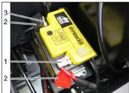
1NoIOXKeJIbHbI NOJIOC
2 PoiHcHbKoJIpaQok
3 OTPuataeHbHn noHoc
→ NocTabntb aKKMyJrTOp B depKaTeNb aKKMyJrTopa.
→ПочнОпрИВИNTИБФИКСАТОРБИHAДИЗЕAKKUMYЛТOPA.
→ Μοικηουήθ ΜοικόΗβγαχμΜ (κρa-ch𝑏ι καδεύβ) κνοικόγ (+).
→ ΠΟДΚΙΝΥΝΤΑ ΜΟΙΝΟχΗΜ 3αχΜΚΟΓημιατελβίνους ΜΟΙΝΟχΗΜ (−).
→ HadeTb konnaKneMM.
→ PpOBepuTb, HAdEeKHO Jn 3aunuaet Cma3ka NOnIOca aKKyMnyTopa n KJemMbI.
PpOBepntyypoBeHb3JKeTpoNtA B aKkMyJrTope nOTkoppeKtnPoBaTb erO (ToIbKO B MaIoo6cLyXnBaembIX aKkMyJrToPax C npo6kamn aKkMyJrToPbIx 3JeMeHTOB)
OCTOPOXHO
Onachocmb nopekdehura!
B akkymympax, e komopbte 3anu- 8aemc kucnoma, cneoyem peynpHO npoeepmb ypoeeH xudkocmu.
BbIBHTNb BCE npo6Kn aKKMyJrTOpHbIX 3NJEMEHTOB.
KNCJOTOMePOM B3aTb npo6bI n3 KaXdo-TO 3NEMEHTA.
-ПлOTHOCt bэлКТрОЛТа ПОЛНOCтьоЗapяжehHOrO aKKyMЛТopa paBHa1,28 Kr/π npT emNepaType 20 °C.
-П notHocTb 3neKtpoJnTa YaCTNuHo 3a-paJxHeHOrO aKKMyJrToPa paBa OTO1,00do1,28Kr/π.
-Bo BCEX 3IeMeHTax IIOHTHOCTb 3JNEKTPoNtA DOJXHa 6bITb OuHAKOBOJ.
PpO6bl 3JNEKtpoNTb1 BblNTb B Te Xe CAMble 3JEMeHTbl.
→ PnCINUKOM HN3KOM YPOBHE KINKOCTN 3aINTb B 3eMeHtBi DnCTuNlnpoBAHHyO BOY DO OTMETKn.
3apAaTb aKKyMnyTOp.
→ 3aBHTnTb npo6Kn aKkMyrTophix 3NEMEHTOB.
3apdka akkymyTopa
ONACHOCTb
Onachocmb noJyehnmaPmabM!
ONACHOCTb
→ Ppu o6paueHuu c akkymnyamopamu co6niodam npaeuna mexhuku 63- onachocmu. Co6niodam uHcmpykuu no 3Kcnnyaamauu, npedocmaeHnyu u3o0umem 3apdHO2O ycmpoUcmea.
Onachocmb noepexdehura!
3apxamb akkymnymop moIbKO c nOoubu cooemcmyoue20 3a-paHO2O ycmpoucmea.
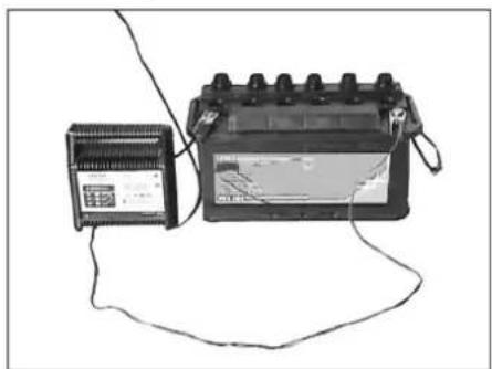
BbIBHTNb BCE npo6Kn AKKyMnyTOpHbIX 3nEMeHTOB.(TOJIbKO IIN HEO6CnyXnBAeMOrO AKKyMyrTopa)
CoeHNHTb NOJXKTeHbHn npOBd (+) 3apAHorO np6opa c noJXKTeHbHbIM NOJIOCOM aKKMyIaTopa.
CoedHHnHb OTpNAteJIbHbI npBOoD (-) 3apJHoro pnp6opacOTpNAteJIbHbIM NOHOCM AKKMyJrTopa.
→ BKNIOHTB Cetb WTeNCeJIbHyHO BNIKy IN BKNIOHTB 3apAHyI np6Op.
→ AkkyMylTOp CNeIyEt 3apJxKaTb 3a-pyHbIM TOKOM C MHNMaJIbHOI CNIOI TOKA.
→ Pocne 3apAkn AKKyMylrTopo OTCOeHNHTb 3apAHOe yCTpOJCTBO CHaYAnOT CETN, 3aTEM OT AKKMyIyrTopa.
3aBHTnTb npo6Kn aKKyMylrTophbx 3JIeMeHToB. (TOJbKO IIN Heo6cnyxuBaEMOrO aKKyMyIrTopa)
BbHytb akkymyIaTOp
OTKJIIOHTb NOIIOCHBn 3aXIM OT OTPNUateJIbHOro nonIOca (-).
OTKINHOUYTB NOHCHB3aXMMOTNOJXHTENbHORO NOHOCA (+)
Ocna6ntbΦKCaTopbHa dHnue aKKMyJrTopa.
BbHytbakMyJrTopn3depkataeJia.
→ NcnoJb3OaHHbI aKKyMyJrTOp cNeIy-et yTuIN3uPoBaTb CoNlacHO DeICTByHouIM PpeDnucAHm.
PpOBepnTb ypoBeHb TopMo3HoJ XNkOcTn I DOJIb TOpMO3HyO XNkOcTb
ONACHOCTb
Onachocmb nonyuehnmaaM!
Bceea npu noHmom peepeyape 4n c6opa mycopa ycmhaanueambnpedoxpahumelhble umahu.
3aumy bInonHmB moIbKO 3a npedamu onachou 3OHbl.
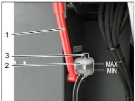
1 DepeKaeIb npedeoxpaHHTbHOH 7tAHn
2 Bauchok TOPMO3HON XINKOCTHI
3 3anopnna Kpbuika
→ПоДнЯТБунКердЯ MycopaВьерхиЗakpenNTb npedoxpaHntBhbie wTaHn,cm.лаву "OnopoxHeHne ByhkepaДЯ Mycopa"
PpOBepntb HauHne DoCTaTOHoro KOJIINueCTBa TOPMO3HOJ KUKOCTN B COOTBETCTBYOUEM 6aueke.
Yka3aHne
YpOBeHdoJKeH HaxoDnTbcMmMyOTMeTKamMIN (MnH.) n MAX (MaKc.).
→ Pn Heo6xOaMocTn DoJeTe NMeo- uOyocB npOdaKe DOT-tOpmo3HyIO XNdkoCTb.
PpOBepKa ypoBn IdoJIbKa MaCna △ONACHOCTb
Onachocmb oxoza!
→DambdeuzamenIOocmbmb.
→ PpOBepKy ypoBnMa Macna B DnRatene OcyuecTBnTb, camoe paHHee, yepe3 5 MInHyT NocJe BBkNIOHeHn DnRatEnr.
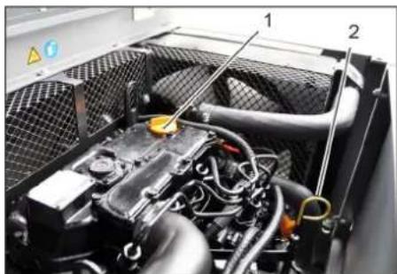
1 Kpbiuka MacnoHaJIINBHOI rOpNOHBi (DniratEnb)
2 YkaataIb ypOBH MaCna
→ BbITaHyTb yka3aTeNb ypOBHMaCna.
→ BbITEpeTb yka3aTeJIb N BCTaBNTb erO CHOBA.
→ BbITaHyTb yKa3aTeJIb ypOBHMaCna.
→ ChTb nokaahne ypoBHa macna.
CHOBA BCTaBtB MaCJIHbI uyn.
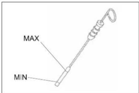
- YpoBHeb Macna DoJIkeH HaxOHTbcBcMeKdy OTMeTKamn MIN" n "MAX".
-EcIn ypoBeHb MacIa HnKe OTMeTKn MIN",doNTb MacNo. - He 3aJIbBaTb MaCNo BbIe OTMeTKN MAX".
OTBnHTMbKpbIuKyMaCIOHaJIINBHOI TROPOBHbI.
3aINTb MOTOPHoe MacNo. BnMacna yka3aB BrnaBe "TexHueCKne daHHble".
3aKpbItb KpbIuKy MaCIOHaINBHO rop- IOBInHbl.
→ NdoKdaTb, KaMmHmMy, 5 MmHyT.
PpOBepuTyPOBeHbMaCnB DnBnraTe- ne.
3aMeHbMaCNo DBuratEnI MaCnHaBmΦnBtp OCTOPOXHO
Onachocmb oxo208 oopum Momophbim MacnOM!
→dambdbuaamemioocmbimb.
→IIOJROTOBnTBMACNOC6OPHNKOBbEMOM HeMeHee6π.
→ TaTb DnRrTaTeNIO OCTbITb.

→ BbIBHNTnTb pe3b6oByIO npo6Ky.
OTBnHTNTb KpbIuKy MaCNoHaJIINBHOI ROPNOBHJI.
CnHbMacNo.
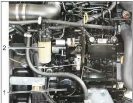
1 Filter motornog ulja
2ToNNBbHbIΦnIbTp
OTKpyTbMaCnHbIΦnTbTp.
OuNTb 3aKMM yNtHTeHbHbe NOBepxHOCTn.
→ ΠepeД yCTaHOBKо Cma3aTb MaCJOM yNIOTHHeHne HOBOrMaCJIraHOrOФЛь-Тра.
BCTaBnTb n BpyHyIO 3aTMyHb HOBbIMacnHbI qNtbp.
3akpyntb npo6ky-3aarrnyukdy nIBA macna BmecTe C HOBbIM yNIOTHHeHEm.
MOMeHT 3aTJKKn:25HM
3aINb MOTOPHOe MacNo. BnN KOINueCTBO MaCna yKa3aHbI B rJaBe "TexHnueCKne daHHbe".
3aKpbItb KpbIuKy MaCNoHaHnBHOr ropIOBnHbI.
→ДаыдИгателюпоработьВтуЕне пимерно 10 cekyн.
PpOBepuTyPOBeHbMaCnB DnBnTaTe-
PpOBepuTb TOnnBHyI pNtBtp
PPOBepuTb TOnnBnHbI ΦnltpHa npedmet 3arpa3HeHn.
→ Pn Heo6xOaMocTOn OuHCTNTb TOnNHBnΦnBtp N KOpNyCΦnBtpa,ecn Notpe6yETc 3aMeHNb TOnNHBnΦnBtp.
3aMeHHTb TOnnBHBbI ΦnBtp

1ToJIINBHykpan
2 TonJIINBHyI ΦnIbTp
3aKpbTbTOJIINBHykPkaH.
OTBHTbN3aMeHHTbTOnnBBbIM
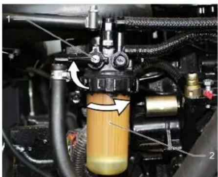
1ToJIINBHykpan
2 TonJIINBbHbI ΦnIbTp
YBELOMNEHNE
Ipepe ycmahOBKo 3aonHmmb monJueHbI qunbp d3eBbIM monJueOM.
→ PnKpyTb HOBBI TOINBBHbI ΦJBtp.
3aBnHTNb TOnNMBHbIΦnJIbTp c KpyTARUM MOMeHTOM 20HM.
OTKpbItbTOnnNHBbI KpaH.
CnB KOHcHcTa H3 BOOOTeNTeTnA 13eJbHOro TOnnBa.
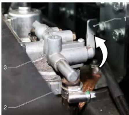
1 TOnJIbHbI KpaH
2Uawa macnooTdennten
3 BDOOTdJIITeJIb
→3aKpbItbToTOnnMbHbIKpHaH.
OTKpyNTb n onopoxHHt b hauy macno-OTdEnHTEJ.
→ Pnukpyntb yauy macnooTeiTeia.
OTKpbItbTOnnBHykPaH.
IpoBepntb ypOBeHb IdoJIHTb MacNo dIra rnpabnuecknx CnCTeM YBEDOMJEHNE
Pe3epeyap dna c6opa Mycopa He doJxeh 6bim npunodHm.
OTKpbItbKOxKydBnIaTeTna.
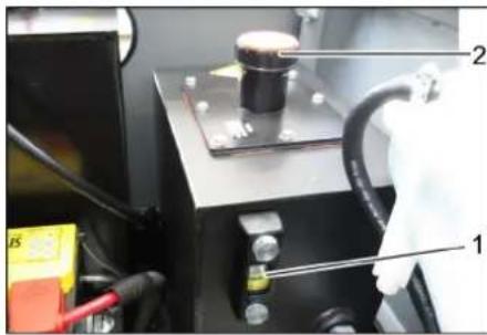
1 Macnomephoe cTeKIO dIy rIpaBnHecckoR O macna
2 Kpbilka, OTBepCTme Dnla 3aINbKm Macna
PPOBepntb ypoBeHb Macna B rnpabBnueckoCNCTeMe B CMOTPOBOM OKHe.
-уровь macnadoJikeH haoDntbceMeKdyOTMeTkamn MIN"u MAX".
-EcInypoBeHbMacJHnKeOTMeTKN MIN,DOINb MacNo.
OTKpyTntb 3anOpHyIO KpbIuKy OTBepCTnA J3aNNBKn MaCna.
OuNTb 06NaCTb 3aINBKn.
3aNTbMacnoIgIpaBnuecknx CnCTeM. Bm Macna yka3aH B rnaBe "TexnueCKne daHHble".
3aKpyTntb 3aOpHyo KpbuKy OTBepCTNA Dnra 3aNvKn MaCna.
PpOBepntb rnpaBnueckyo yctahOBky
YBELOMJIENHE
Pemohm zuopaueckou ycmaHOBku npoeodmb monbko c npueneeHEm cepEucho cnjkbu dpmbk Karcher.
3aФнкспуTe CTOrHouHbI TOpM03.
3anyctntb DnBraTeJIb.
PpOBepnTb repMeTNUHocTb Bcex 6e3 NCKJIIOUHeHnraIpaBnuecknx IJNaHROB n COeINHeHn.
PpOBepntb ypoBeHb oxnaKdaIOuee XIKKOCTN
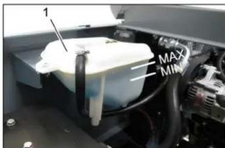
1 KomnHeHcauOnHHb 6aOpKaJaTaOpa KIOKoCTHO OXJaXeHnA
→ PpOBepnTb ypoBHe npx xOIOHOM DnRaTeNe.
→ PpOBepntb ypoBeHb HAnOnHeHnKOMneHcauOnHHoro 6aKa paDnaTopa XnKDocTHORO OXJaXKeHn.
YpOBeHb OxJaXdAHOuee XnKoCTn DOJIKeH HaxOOnTbcM EKdy OTMeTKa-MN MIN (MnH.) n MAX (MaKc.).
PpOBepntb nOuHCTnTb paHaTOp BOBblrnpaBnueckoro Macna △ONACHOCTb
Onachocmb nolyehua oxo2o u ownapueaHua!
→ Damb bdoHomy paduamopy ocmbimb meeHue He MeHee 20 MuHym.
YPOBHeOxJaKaDaIOueBBOBtOT BOJDAHOROPaNaTOpa npOBepaTeCnHa KOMNeHcAioHOHOM6aueKepaNaTOpa XNdkoCTHO OXnaKDeHn.
CM. rnaBy "PpOBepka ypoBn oXlaKdauue BODbl".
OuNTb nlaCTnHb paHaTopa. YcTaHb 3aRpa3HeHne C NOMoubIO MRAKO ueTK, CxAToRO BO3dyxA INI NOd He6oBbIM DaBJIeHNEM BObl.
PpOBepnTb repMeTNHOCb 7JNaHra paNAtopa u COeINHeHn.
OuHCTHTB BEHTNIArTOp.
PpOBepka noDMetaoero Bana
3anyctntbBnraTeIb.
→ПОДнЯТьdoynopape3ePByapdЯc6o-paMycopa.
BbIKHouThBdNraTeJIb.
3aФнксуTe CTOrHouHbI TopMo3.
YcTaHOBnTb IpeOxpaHnteNbHbIe WtAHn DnI ONOpOXHeHn NOHrTOpe3epByapa.
→ Ydannb c noMetaioo Ro Bana HAMOTabuiec JHeTbI N BepeBKn.
BbHyTbppeOxpaHHTeNbHbIe WtAHn.
3anyctntbDnurateta.
Onyctntb pe3epByap nIra c6opa Myco-opa B HauanbHoe noNoxKeHne.
BbIKHouHTb DBnraTeJIb.
3aMeHa nOdMeTaIooero BaIa
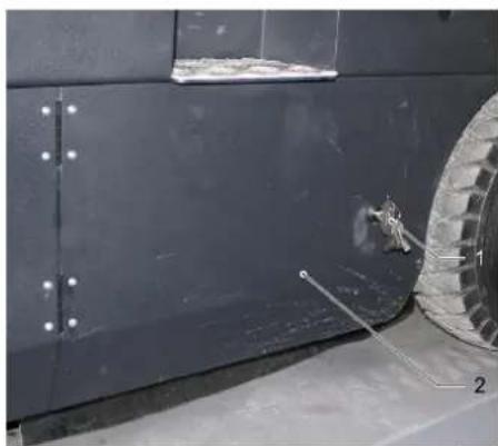
1 Kniou
2 BOKOBaB O6uNvBa
→ PONHHTB BBEpx 6yHKep DnMyMycopa NPOINEPETb C NOMOuIbIO NpeDOxpaHITeBHO WTAHN.
OTKpbTb 6OKOByIO nAHEnb C NOMOJIbIO KIOHA.
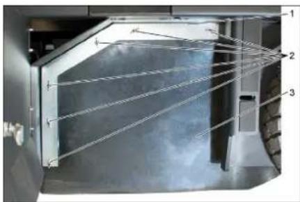
1 Ck06a
2 BapawkoBraKa
3 BokBoe yNoTHeHne
OTBHTb6apawkoBBieraKn.
CHIMMTECKo6y.
OTBnHTntb 6apaWkoBbIe raIKn, pacnoJIOXKeHHbIe Ha NIOCKO CTOnOPHOI WaiBe, OT 6OKOBOrO yNtOHEnHn CHaTb NIOCKyIO CTOnOPHyIO Wai6y.
OTKINHyTb HApyKy 60KOBOe yNIOHTHeHNE.
→ BbINHTnTb KpEnexKbI BNTH DepeKaTeJI NaDMetaUeBO Bana N nobepHytB HapyKy npneMHoe yCTpoNCTBO.
BbHyb noDMeTaIOU BaJ.
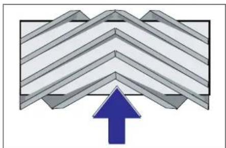
PacnoIoxKeHne IOnMeTaUoJero Bana npu yctaHOBKe No HAnpaBNeHIO DnIXKeHHN (BvD CBepxy)
Yka3aHHe: Pn yCTaHOBKe HOBOr NOIMTeAIOUeRO Bana CNeIbTb 3a NONOKeHNEM UeTHNbl.
YCTaHOBHTb HOBbI NOmTaHOUcHn BAN. Na3bI NOmTaIOUe BOA dONK HbI COBNaCTb C BbICTyNam6BaHaHCupa.
Yka3aHne: Nocne yCTaHOBKn HOBOr NOmMetaIOUeRO Bana Heo6XODIMO CHOBa OTpeRyIuPObAteNIOCKOCTb NOmTeHaHn.
PpOBepKa n KoppeKTHpOBka nIIOCKoCTn NOmTaHnA dNn NOmTaUoJero Bana
BbIKIOHTb BcAcbIbAOuN BeHTnJIa-Top
→ NocTaBtB NOMMetaIooyMoAunHy HaPOBbI rJaDKn NOn, NOKpbTbI BUNMbIM CNOEM bJIIN JIN MeJa.
→ C NOMOUIbIO pblHara ynpaBHeHnO nOyCTNTb NOdMeTaOuN BANIK N DaTb emY npa6oTaTb (OK. 10 c).
→ PnDnHbTb NpDMTaHouuBn BaJ.
→ DaTb annapaTy 3aHnH xoD.
→ PpOBepntb pIOCKOCTb NOmTaHnA.
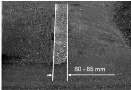
PpOΦnIb PNOMeTaHn DOnJKeH NmEe TB BnD paBHomePHO npMoyrOJIbHnKa WnpHoi 80-85 MM.
Perynpobknapoqnna noDmetaHn

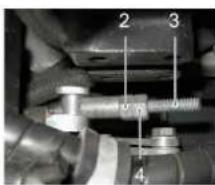
1Пукунна
2 PerynpoBouHa raKa
3KoHTpraIka
4 Pe3b6OBoI uTOK
OtperynipoBbT noJIOxHe npoOpnIy NOIMeTAHNI PyTEM nepeCTaHOBKn yCTaHOBOUHOrO BuHTa.
PpOBepuTb PNOCKOCTb NODMeTaHnA.
PpOBepKa N KoppeKtnpObKa npoФnna NOmTaHnA JI 60KOBbIX uTeOK
→ PpInnoDnHb60KOBbIe 1eTKn.
→ NocTabNbNIOMDaTcHIOUHO MaunHy Ha pOBHbI rJaDKn NOJ, NOKpbITbI BnIMMbIM CNOeMbIN NmMea.
Onyctntb 60koByo uetkn n daTbe en npap6oTaTb np6n.10 ckyHd.
→ PpInnoDnHb60KOBbIe 1eTkn.
→ DaTb annapaTy 3aHnXoD.
PpOBepuTb PLOCKoCTb NOmTeHaHnA.
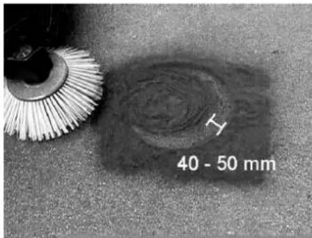
HpiHa npoФnna nOmdTaHn DaONKha coCTaBnTb OT 40 Do 50 MM.
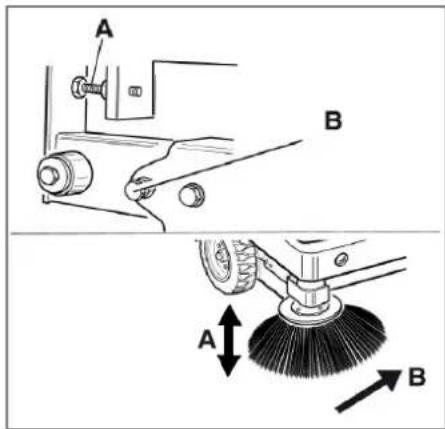
OTperyIInpoBaTb NIOJXeHne NIOCKOCTNIOMDTaHnC NOMOIbIO DByX YCTaHOBOUHbIX BHTOB.
PpOBepuTbPiocKoCTbPiMeTaHnA.
YcTaHOBnTb 6OKOBbIe yIIOITHeHnA ONACHOCTb
Onachocmb noJyuHua mpaem!
Bce2da npu noHjamom pe3epeyape 7c6opa Mycopa ycmhaenueambnpedoxpahumelhble umanzu.
3aumy 8binoHmB moIbKO 3a npedamu onaCHO 30hbl.
→ POnHrTb BBePx pe3epByap IJra c6opamycopa n 3aФuKcnpoBaTb C NOMOuBnPpeDOxPaHHTeBHOI uTaHn.
OTKINHyTb HABepx npdeoxpAHNTB-HyIO uTahry IaONOPOXHeHn NOHaToro pe3epByapa N BCTaBnTb ee B depXaTeNb (npdeoxpAHNTbHbI)
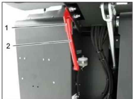
1 DepeKaeIb npedeoxpaHHTeJIbHOJ
2 PpeoopaHnteIbHaIaTaHa
OTKpbItb60KObyIO naHeJI, KaK OINcAHO B rnaBe ,3aMeHa IOMDetaUoeroBana" Bblie.
Ocna6ntb 6 bapaWkoBbix raeK ha 6o-KOB0I NIOCKO CTONOPHOI WaiBe.
Ocna6ntb 3raa (SW13)Ha nepe-dHei nlocko CTOnOpHoi waiBe.
Hakimatb6okoboe ynnotheHne BHN3 (npoonbHOe OTBepCTne) Do tex nop, noka erO kpaI He OKaKeTcHa paccto- 1-3 MM OT nona.
→PnBnHTb NIOCKyO CTONOPHyo 6v.
→ NOBTOPnTB nocneIOBATEbHOCTb dIpyro CTPOHb yCTPOHCTBa.
BpyHyO ouHCTnTb fNtbp dna nblnn
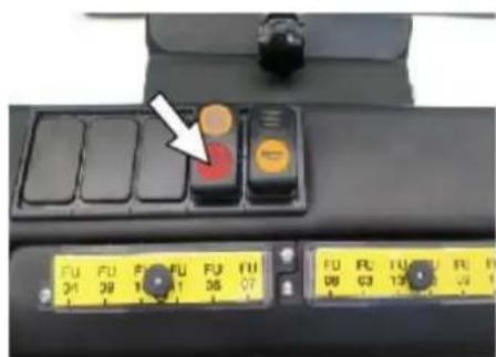
→ BKnIOuHTb YnCTKy CnIbTpa BpyHyIO,
PpOBepntb/3aMeHHTbΦnIbTp dnn nblnn
△NPEDyynPEXKDEHNE
Onachocmb nonyuhenmaPam!
→Ppu pa6ome c qunbmpoabnHOU ycmahOBKOHOCumb Macky dny 3auuMbI om nbiu. CobnoaBm npednucaHua no mexHuke 6e3onacHocmu o omHoweHuO obpaueHua c MeKoJ nbIbIO.
→ BbINOJIHHTb YNCTKy FJIbTpapJnBJIc n NOMOUsb KONKn OYNCTkFJIbTpA.
OnopokHNb pe3epByap nra c6opa mycopa.
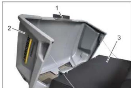
1Блokировka кршкynустяпства
2 Kpbuika npmbopa
3 Kpbiuka qnIbItpa
OTKpbIb 6JIOKNPOBky.ДЯЗTORO HeoBXOДIMO OTKpyTITb BnHT C rONOBKO BBNDE 3Be3DOHKn.
OTKmHyTb KpbIuKy npnbopa Bnepe
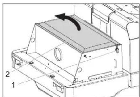
1 3amok, kpbuka qnibtpa (2x)
2KpbuHaKaΦnIbTpap
OTKpbItb 3AMOK.
OTkpblKpblUkyΦnIbTpα.
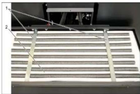
1 PonepeuHbe paonopkn
2ПьлевовФиЛТр
Yka3aHne
→ PpOBepntb qnIbTp nbIN, B cIyuae Heo6xOIMOCTN pON3BecT NcCTky INN 3aMeHNTb.
3amEny fnnbTpa nbinn pa3pewaeTc npBOOINTb TOJbKO COTpydHnKAM cepBUCHO CNyX6bl pnpMb Karcher.
HaTeB 3aФИКСИРОВАБТКрБИKKу ΦЛБТРа.
PpOBepKa n perynnpoBka KlnHOBOporpeMH

KlnHObbl pemeH npn daBneHN 10 kr. DOnJKe HnpOBncaTb npN5n.Ha 7-9 MM.
→ HataKeHne KInHOBOrpeMnYcTa-HabJINBaEeTcYyONHOMOeHHbIM pa-60THNKOM cepBnCHO cnK6bl.
PpOBepKa n 3aMeHa BO3dYuSHoRo fNbTp a
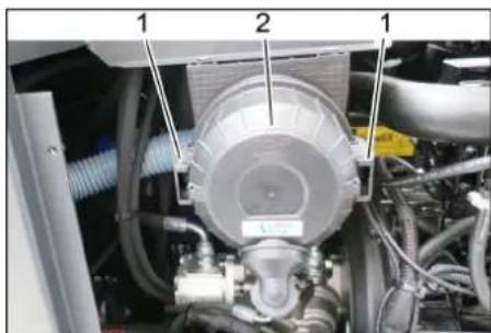
1 BloKIpOBka
2 Kopnyc Bo3dyuHoro qnilbtra
→ Chr8b 60KOByIO nHaHeJIb.
→ CHaTb KOpnyc Bo3DyUHoro qInhTpa.
3aMeHHTb nATPOH BO3dyuHoro qnIb- Tpa.
Yka3aHHe: MoTaxKHOe NIOXKeHHe - BeHTnIaIcNHOHHe OTeBepCTne HAnpaJIeHO BHN3 (CM. PNCyHOK).
OuHCTHTb ceHTpObeXhBc cenapaTop
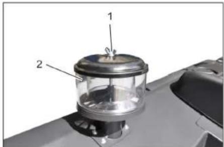
1 Bapaшковая тайka
2 ζεντροδεχκήν cεπαρατόρ
OTBnHTntb 6apaWkoBvIraIKyHaueHtpo6exHOM cenapatope.
OuHCTnTb ceHTpo6exKn bcnapaTop.
3aMeHa npdeoxpAHnteNei

1 Raika cnprmoHaKaTko
2 Kpbiuka ruiKa c npedeoxpaHITeIaM
BbIKpyTntb raiKy c npoJoBHOHaKaTkoI
OTKpbItb KpbIuKy Ha npedoxpaHnteH HOM RAUKe.
PpOBePnTb npEdoXpaHnteJI.
HeicnpaBbIe npedoxpaHntn 3ameHHTb.
Yka3aHne: IcnoIb3OBaTb TOJIbKO npeDoXpaHHTeN C OINHaKOBbIM 3HaYeHN-EM.
Yka3aHHe: PpeOxpaHntB FU 01 HaxoDNTcB NIOkAnOTHom IpocTpaHCTBe.
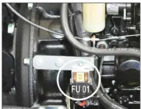

Chairman of the Board of Management
Director Regulatory Affairs & Certification
YIIOJIHOMOueHHbI COtpyDnIK NO BeDeHNO DOKymHeTOOBopota:
S. Reiser
Alfred Karcher SE & Co. KG
71364 Winnenden (Germany)
Tel.: +49 7195 14-0
Fax: +49 7195 14-2212
Winnenden, 2020/01/01
www.kaercher.com/REACH
Garancia
Chairman of the Board of Management

S. Reiser
Director Regulatory Affairs & Certification
71364 Winnenden (Germany)
Tel.: +49 7195 14-0
Fax: +49 7195 14-2212
Winnenden, 2020/01/01
www.kaercher.com/REACH
Záruka
Ovladaci panel Pedaly
ilustrace
2006/42/ES (+2009/127/ES)
2014/30/EU
2000/14/ES
Pouzité harmonizačni normy
EN 60335-1
EN 55012: 2007 + A1: 2009
EN 55014-2: 2015
2000/14/ES: Prlloha V

Chairman of the Board of Management

S. Reiser
Director Regulatory Affairs & Certification
Zplnomocnena osoba pro sestaveni dokumentace:
S. Reiser
Alfred Karcher SE & Co. KG
71364 Winnenden (Germany)
Tel.: +49 7195 14-0
Fax: +49 7195 14-2212
Winnenden, 2020/01/01
Splośna navodila. SL 1
Varstvo okolja .SL 1
Garancija .SL1
Pribor in nadomestni deli SL 1
Simboli v navodilu za obrovanje SL 1
Simboli na napravi . . . . . SL 1
Namenska uporaba.. SL 2
www.kaercher.com/REACH
Garancija
Zadevne directives EU:
2006/42/ES (+2009/127/ES)
2014/30/EU
2000/14/ES
Chairman of the Board of Management

S. Reiser
Director Regulatory Affairs & Certification
Pooblascena oseba za dokumentacio:
S. Reiser
Alfred Kärcher SE & Co. KG
71364 Winnenden (Germany)
Tel.: +49 7195 14-0
Fax: +49 7195 14-2212
Winnenden, 2020/01/01
www.kaercher.com/REACH
Gwarancja
2006/42/WE (+2009/127/WE)
2014/30/UE
2000/14/WE

Chairman of the Board of Management

Administrator dokumentaci:
S. Reiser
Alfred Kärcher SE & Co. KG
71364 Winnenden (Germany)
Tel.: +49 7195 14-0
Fax: +49 7195 14-2212
Winnenden, 2020/01/01
www.kaercher.com/REACH
Garantie
Directive UE respectate:
2006/42/CE (+2009/127/CE)
2014/30/UE
2000/14/CE
Norme armonizate utilizezate:
EN 60335-1
EN 55012: 2007 + A1: 2009
EN 55014-2: 2015
Norme de aplicare nationale:
Chairman of the Board of Management
Director Regulatory Affairs & Certification
71364 Winnenden (Germany)
Tel.: +49 7195 14-0
Fax: +49 7195 14-2212
Winnenden, 2020/01/01
VseobecnePokyny SK1
www.kaercher.com/REACH
Záruka
Ovladaci panel Pedale
Obrázok ③
1 Oblsuzna pacha Zdvihnut/spustit zametaci valec
2 Obsluzná páčka Zdvihnutie/spustenie zametaceho valca
3 Obsluzná páčka Zdvíhanie/spúst'anie bočnej kefy
4 Oblsuzná páčka
Otvorit' / uzavriet' klapku nádoby
5 Kontrolné lampy a displejej
6 Vypinač ventilatóra a Čistenia filtra
Stredné poloha: Čistenie filtra a ventilatór vyp
Poloha vzadu: Ventilátor zap
Poloha vpredu: Čistenie filtra zap
7 Spinač húkáčky
8 Poistky
9 Zámok zapalovania
Symbol vlákná ziarovky: Predhrievanie
Poloha 0: Vypnut motor
Poloha 1: Zapalovanie zap
Poloha 2: Naşartujte motor
10 Prestavenie otacok motora Plynovy pedal
11 Parkovacia brzda
Obrazok
1 Brzdvy pedal
2 Plynovy pedal dopredu / dozadu
Kontrolné lampy a displejej
Obrázok D
2006/42/ES (+2009/127/ES)
2014/30/EU
2000/14/ES
Uplatnovane harmonizovane normy:
EN 60335-1
EN 55012: 2007 + A1: 2009
EN 55014-2: 2015
2000/14/ES: Priloha V

Chairman of the Board of Management

S. Reiser
Director Regulatory Affairs & Certification
71364 Winnenden (Germany)
Tel.: +49 7195 14-0
Fax: +49 7195 14-2212
Winnenden, 2020/01/01
Opé napomene . HR 1
Zastita okolisa .HR 1
Jamstvo .HR 1
www.kaercher.com/REACH
Jamstvo
U svakoj zemplji vaze jamstveni uvjeti koje je izdala naša nadležna organizacija za distribuciju. Eventualne smetnje na stroju za vrijeme trajanja jamstva uklanjamo besplatno ukoliko je uzrok greška u materijalu ili proizvodnji. U slučaju koji podlijiže garanciji obratite se, uz prilaganje potvrde o kupnjni, Vašem prodavaču ili njablžoj ovlaštenoj servisnoj službi.
Chairman of the Board of Management
S. Reiser
Director Regulatory Affairs & Certification
71364 Winnenden (Germany)
Tel.: +49 7195 14-0
Fax: +49 7195 14-2212
Winnenden, 2020/01/01
Opste napomene. SR 1
Zastita zivotne sredine. SR 1
Garancija .SR 1
Pribor i rezervni delovi . . SR 1
Simboli u uputstvu za rad SR 1
Simboli na aparatu. . . . SR 1
Namensko korijscenje . . . . . . SR 2
Predvidiva pogresna
upotreba. SR 2
Prikladne podloge . . . . SR 2
Sigurnosne napomene .SR 2
Sigurnosne napomene
vezane za rukovanje...SR 2
Sigurnosne napomene
vezane za voznju . . . . SR 2
www.kaercher.com/REACH
Garancija
U svakoj zemlji vaze garantni uslovi koje je izdala naša nadlezna distributivna organizacija. Eventualne smetnje na uredaju za vreme trajanja garancije uklanjamo besplatno, ukolko je uzrok greška u materijalu ili proizvodnji. U slucaju koji podleže garanciji obratite se sa potvrdom o kupovini Vašem prodavcu ili najblioj ovlašćenoj servisnoj sluzbi.
Pribor i rezervni delovi
OPASNOST
U cilju sprečavanja opasnosti, popravke i ugradnju rezervnih delova sme izvoditi samo ovlašćena servisna služba.
- Sme se koristiti samo onaj pribor i oni rezervni delovi koje dozvoljava proizvodač. Originalan pribor i originalni rezervni delovi garantuju za to da urežaj moze raditi sigurno i bez smetnji.
Dodatne informacije o rezervnim delovima dobicete pod www.kaercher.com u delu Servis (Service).
Simboli u uputstvu za rad
△OPASNOST
Ukazuje na neosredno pretecu opasnost koja dovodi do teških telesnih povreda ili smrti.
UPOZORENJE
Ukazuje na eventualno opasnu situaciju koja moze dovesti do tešikh telesnih povreda ili smrti.
△OPREZ
Ukazuje na eventualno opasnu situaciju koja moze dovesti do laksih telesnih povreda ili izazvati materijalnu stetu.
PAZNJA
Napomena koja ukazuje na eventualno opasnu situaciju koja moze izazvati materijalne stete.
Simboli na aparatu
| Opasnost od opekotina na vrelim površinama! Pre obavljanja radova na uredaju treba sačekati da se izduvni sklop dovoljno ohladi. | |
| Radove na uredaju uvek obavljate noseci odgovarajuće rukavice. | |
| Opasnost od prignječenja uvlačenjem mevuPokretne delove vozila | |
| Opasnost od povredaPokretnim delovima. Zabranjeno zahvatanje rukama. | |
| Opasnost od požara. Ne usisavajte zapljene ili užarene predmete. | |
| Prihvatnik lanca i mesto oslananja krana | |
| Prihvatna mesta za autodizalicu | |
| Maksimalan nagib podloge prilikom vožnji s izdignutom posudom za prljavstinu. | |
| Dopušteno je savladavati samo uspone do 18% u smeru vožnje. | |
| Opasnost od oštećenja! Filter za prasinu ne sme da se pere u vodi. |
Namensko korijscenje
2006/42/EZ (+2009/127/EZ)
2014/30/EU
2000/14/EZ
Primenjene uskladene norme:
EN 60335-1
EN 55012: 2007 + A1: 2009
EN 55014-2: 2015

Chairman of the Board of Management
S. Reiser
Director Regulatory Affairs & Certification
71364 Winnenden (Germany)
Tel.: +49 7195 14-0
Fax: +49 7195 14-2212
Winnenden, 2020/01/01
O6u yka3aHnB. BG 1
Ona3BaHe Ha OKoJHaTa Cpea BG 1
Tapaun. BG 1
PpinaIeXHocTn pe3epBHN
chaTn BG1
CIMBOJN Ha YnbTBAHETO 3a
ynoTpe6a BG 1
CnmbonHa ypea...BG1
Ynotpe6a no npedHa3haueHne BG 2
PpeBnDnma rpeWHa ynoTpe
6a. BG 2
PoiDxoIaIuHacTnIKN..BG2
Yka3aHn 3a 6e3oNaCHOCT...BG2
Yka3aHna 3a 6e3oNaChOCT npn
obcnykbahe. BG 2
Yka3aHnna 3a 6e30anachocT npn
peKIM DnBxKeHne...BG2
UpeiC DnBnraTeN C BbTpew
HOrpeHe. BG 2
UpeDn C BVCOKO n3npa3BaHe BG 2
UpeDn CbC 3aunTeH nokpmb 3a
BODaHa BG2
Yka3aHn3a6e3oNaCHOCT3a
TpaHcnpTnpuHe Na ypeDa BG 3
yka3aHn 3a 6e30nachocT 3a
PnDpBxKa N TexHuecko 06
CnyXBaHe. BG 3
ФУнкця BG3
Yka3aHn 3a pa3TOBapBaHe .BG 3
06cnykBaunn yHKUHOHaHn
eJemeHTn BG4
1306paXeHne Ha MaunHaTa
3a MeTeHe BG 4
ObnykBaO none .BG4
Pepa.. BG4
KohtpOJIHnIaMnNnIduCnneB BG 5
IpeDn IyckaHe B EKcnnoataaBg 5
Блokиранe/ocbo6oxdabahe
Ha 3aCTOnOpraBaAsTa Cnnpa-
Ka. BG5
3aBnKBaHe Ha MeTaHata
Maunha 6e3 c06CTbeHo 3a
BnXBaHe. BG5
3aBnKBaHe Ha MeTaHata
MaunHa CbC CO6CTBEN XoD BG5
IyckaneBekcnnoatauia...BG5
06u yka3aHnB .BG5
KoHTpOJIHn IIOIbPjkaun
DeHocTn .BG5
3apejdahe BG5
Eknploatau .BG5
a ce hactpon cedankata Ha
BODaHa BG5
CTapTnpaHe Ha ypeDa..BG5
TbTuBaHe Ha ypeJa. .BG 6
PeknM MeTeHe. .BG6
Da ce n3npa3Hn pe3epBoapa
3a 13MeTeHTo. .BG6
N3KJIIOUeTe ypeJa...BG7
TpaHcnpr BG7
CbxaheHne/CnnpaHe .BG7
PnKn noDpBxka .BG7
06u yka3aHna BG7
Почиствае . BG7
INTEPBAnHaNoDpBxKka BG7
DeyHocTn no noDpBkKaTa BG 8
Iomou npn HennpabHocT..BG 14
TexHnueckn DaHHN BG 15
EC DeKnapaun 3a cbOTBeTCTBnE BG 16

Ppei nIbPBOTo I3nO13BaHe Ha BaWuYpeI pOChETe TOBa
HIO INHCTpykuzy 3a pa6oTa,
deIcTBaIe CnopeI Hero I ro 3ana3e 3a
NO-KbCHO N3N0L3BaHe NIN 3a CNEBaaun
PnTExkATEJ.
06u yka3aHn
Ako npa pao naKoBahe yctahOBnTe TpaHcNoptHa nOpeDa, yBeDoMeTe Mara3Ha, ot KOITcTe 3aKynnnypeDa.
-ПудунпсдгелнITEи yka3aTeHNTe Ta6eJKN Ha ypeJa daBaT BaXn HAnbTCTBn 3a 6e3onacha pa6oTa.
-OCBeH yKa3aHaNraTa B pKOBoDCTBOTO 3a ekCnIIOaTauN TpR6Ba Da CE cna3-BaT N O6UInTe HOpMaTINBHN npeDnica-Hn 3a 6e3ONaCHOCT N npeDnA3BaHe OT 3JNONOlykN.
Ona3BaHe Ha OKoHaTa CpeDa

ONaKOBbUHnTe MaTePnAIn MoRat Da ce peuKnIpaT. Monr HeXBpbIaIe ONaKOBknte Pnp DoMaunHnte OTnaDbu, a rnppeDaIte Ha BTOpUHn CypOBuHn CcIeN NOBTOpHa ynotpe6a.
CTapnte ypein cbbpkaat cehnn MaTePnAIn, noIeXaUHa peKnnpaHe, KOITo MOraT da 6bDat yNtpeBEn NoBToHpO. IopaTIOBaMOnr OCTpaHraBaiTe CTapnte ypei, n3NoJ3BaIKn IOxOJaUN 3a CenTA CnCTEm 3a cb6npaHe.
MToPtoMaTNo,IN3eJIbT N6EH3HbT He 6nBa Da nopaDat B OKoHaTa Cpea.MonpaTe NoyBaTa NOTcPaHraBaiTe CTapnte Macna ONa3BaKn OKoHaTa Cpea.
Yka3aHn3a cbcTabKnTe (REACH)
AkyaHa HOpMaun 3a CbCTaBKnTe 1e
HaMePHTe Ha:
www.kaercher.com/REACH
Tapaanu
Bb BcKa cTpaHa BaKaT rapaHcHnHnTe yCIOBn, Np6JIkyBaHN OT OToP3nPaHata OT Hac DnCTpn6yTopcKa fnpMa. EBeHTy- aHn NobpeN Ha BaIaN ypeN ue OTCpaHnM B pAMKIne Ha rapaHcHnHn CpOK 6e3PiAtHO, Ako ce Kacae 3a DeEkeKT B MaTePnaJIte nn npn npOn3BOvctBO. B rapaHcHNoHE nCnyAe Ce o6bPhTe KbM DnCTpn6yTopa nn Hau-6JI3KnO TOpN3nPAh cepBn3, KaTO npedCTabNt e KacOBaTa 6eJexKa.
PnHaIeJekHOCTn np3epBHN
actn
ONACHOCT
3a da ce u36e2ham ycnoxHeneu, peMOhmume u MOhmaxa Ha pe3epenu yacmu Haypeda da ce u36bpuweam cmo om omopu3upaHua cepu3.
-Morat da ce n3no3BaT caMo npHaJnEeXHOCTN IN pe3epBHN qaCTN, KOITo CaNo3BOJeH NOT pOnu3BOIDNTeJI. OpurnHAnHHTe PnHaJNeXHOCTN IN opuHnHaHNI pe3epBHN qactn rapaHTnpaT cnpyhata n 6e3np6nemHa pa6ota Ha ypeda.
-ДугИ Инфорmaци OTHOCH pe3epB-HHTeЧа'tN MoKTe ДЯ ПОЛУNTe Ha www.kaercher.comВoblaCT CepBu3
CnmboHnHa YnbTbaHeTo 3a ynoTpe6a
ONACHOCT
Ppeynpekdoa 3a Henocpedcmeho apo3uoa onacHocm, kOmo eodu do mexku meenechu noepdu unu do cmbpm.
△PENDyUNPEXKDEHNE
Ppeynpekdoaba 3a 6b3MOxHa onacha Cu myaun, kOmo 6u MoZna da doeede do mekku meeechu noepdu unu cmbpm.
△PENEIA3NIBOCT
Yka3aHue 3a 6b3MOxHa ONaCHA CUmyaUHA, KOJMo 6u Moana da doeede do Neku meNeCHU nopeDu unu MamepuanHu ueMu.
BHIMAHHE
Yka3aHue 3a 6b3MOxHa onacha cumya- uja, kOmo MoKe da doeede do Mamepu- aJHU uemu.
CnmboHa ypea
Yka3aHna 3a6e3oNaCHOCT
Yka3aHn 3a 6e30nacHocT npn 06cnykBaHe
YpebmcnpucncocbeHura3a pa6oma npedu u3non3eae da ce npoeepu 3a 6e3ynpuehO cbcmOHue u eknnoamaauonHa cueypHocm.Ako ypeBm He e o omluHo cbcmOHue, u3non3eaHemo My e 3abpaHeno.
Da ce cna3bam yka3aHura ma 3a 6e3o-nachocm npu pa6oma cypeda e onacHu 30HU (HaNPUMep Ha 6eH3uHocmaHuu). 3a6paHeHa p6omama ebe 83pu6oONaCHU nOmeueHua.
ONACHOCT
Onachocm om HapaHyaHe!
He u3non3eaume ypeda 6e3 3auumen nokpu npomue nadau npedmu e obnaemu, kbdemo cbuecmeyba 6b3- moxnocmma, ocbnykeaumn nepcoHan da 6bde 3acezham om nadau npedmu.
06cnyk8aumo nuce mpy6ea da u3- non3ea ypeda cnopep npednucnura ma. Ioo spe me ha paoba mo mpy6ea da ce cbo6pa3rae c okonhme npedMemu u da eHmua 3a mpemu nuza u oco6eho 3a deua.
Tp6ea da ce cnaeam ochoe Ho MepKume ha npednucnura, npaunama u npaeunHuime, koumo ca eanudhu 3a MomopHu npeeo3Hu cpedcmba.
Pnpdu hauanomo Ha paoba ocbnykbaaomo luue mpr6ba da ce yeepu,yeecuku 3auumhu npucnocobneHua nocmaeHu npabunho u fynkuohupam.
06cnykbaaomo nue ha ypeda e om2o8opno 3a 3nnonyku c dpyu nua unu c maxhomo umyuecmbo.
O6cnjxbao mo luue mpra6ea da e c nIb mno npunenHano o6neKNo. Hoceme 3dpaeu obyeku u36raeaume c6o-6oohomo o6neKNo.
→ Pnoeepaume npedu haenu3ane (ha np.deua).Poeuxeme ce 3a docma-mbyna buumocm!
Ypeobm Hukoza He mpr6ea da ce ocma8a 6e3 had3op,dokamo Momopbmpabomu.Obcnykaaomo nuce mokeda Hanycka ypeda edea mo2aabaKoama Momopbme yachan,ypeobmeocuayen npomue HnpedhamepeHu obxeknue u KIOUoym e U3adeH.
3a da ce u36e2he HeKOMnemehmHa ynompe6a Ha ype6a, da ce u3eaDu KIIO4a.
Ypeobmmpra6ba da ce u3non3ea ca mo om xopa, koumo ca obyuenu 3a ekc- nloamauyma My u Koumo ca doka3a-nu cnoocbncume cu 3a pa6oma C He2o, u ca Hamoeapenu u3puHNo C u3- non3eaHemO My.
To3u ypeD He e npedHa3Hauen 3a mo-ea, da 6bde u3non3eah om luua (eknouumelno deua) c oapanuenu Hfuzuecku, ceh3opnu uymcmeenu cnocobnocmu u nunca Ha onum u/uni lunca Ha no3haun, ocbeH ako me ca nod had3opa Ha om2oabapuo 3a maxHama 6e3onacnochm nuue unu ca nonyunu om He2o UHcmpkyu, kak da u3non3eam ypeda.
→ Deuama mpa6ba da 6bdaam noo HAD-30p, 3a da ce aapaHmupa, ye Hma da uapam cypeda.
Yka3aHna 3a 6e3oNaChOcT npu peXnM DnKHeHne
ONACHOCT
Onachocm om 3Jnononyka, onachocm om Hapahrahe!
→ Ckopocmma Ha deuxeHue mpr6ea da 6bde aadumupaHa KbM cbomeemHu me ycnoeua.
Onachocm om npoeobpuane npu mbpde 20nEMU HAKTOH.
NopocokaHa dbuxekHuemo npemuHa- eaume camo no haknoH do 18%
Onachocm om pneobpbuane npu heema-bunna ochoa.
Ypeobm da ce deuxku cmo Ha ykpeneHa ochoa.
Onachocm om npeoobpbuzane npu m8bpde 20nem cmpaHueh HAKJIOH.
→ HanpeuHo Ha nocokama Ha deuxkeHue da ce npemuhaeam camo haKIOHU do MAKcumaHNo 10%.
Ypei n c DnraTeN C BbTpeHOr opeHe
△Onachocm
Onachocm om HapaHraeane!
OmeopbIma omeekdahe Ha 2a3o6eme He mpr6ea da ce 3am6apra.
He ce haebekdaume had om6opa 3a ompabomenu a3o8e u He 20 Xbaaume c pbuce (onachocm om u3aapnHe).
→Да He ce dokoceea unu nuna 3adeuxkaa uua MOpop (onachocm om u3apnHe).
OpaobomeHume 2a3oe ca ompoehu u epeHua 3paem, me He mpr6ea da ce eouwam.
Momopbm ce Hykdae om npu6n. 3-4 cekyno 3a cnupahe ha xoda cned u3-2acnae. B mozu nepuod om epeme He-npemehno ce dpbxmte hadaney om obnacmna Ha 3aduxxahe.
YpeDn C BucOko n3npa3BaHe
ONACHOCT
Onachocm om HapaHaeBaHe!
→ Ppu pa6oma no eucokomo u3npa38aHe noeduaaime dokpa pe3ep8oapa 3a u3MemeHOMO u 20 nodcuypra8aume.
→ N36bpeaume obe3onacraeaHemoHa Opanachama 30ha camo om6bH.
Ypei n cbc 3aunTeH nokpNB 3a Bodaqa
YKA3AHNE
3aumnua m nokpu 3a 8oda4a (onu) npedna2a 3auma npomus no-epnu nada ucu am. Ypedume obae He npedna2am 3auma npomus npeobpuane!
Yka3aHnna 3a 6e3oNaCHoc 3a TpaHcnpTnpaHe Ha ypeDa
B3ememe nod eHumaHue meaHono 6e3 moBap (meaI npu mpaHCnpm)Ha ypea npu mpaHCnpmupaHe cpeMapKema uTu camoJemu.
→ 3a mpaHcnpmupaHe Ha ypeDa pa3ka-yaume akymyamopa u 3akpenBaume ypeDa cuayrho.
yka3aHnna 3a 6e3oNaChocT 3a NOdRpBxKka N TexHnuecko 06cnykBaHe
Ppeu noucmbahe u noopbkka Ha ypeda, cmaHa ha yacmu unu npemuhae KbM dpya a fyHKua da ce u3KnHO Yu ypeda u da ce u3eaDu knoia.
Ppu paBoma no eEnkmpuueckama ype6ba mpr6ea da ce omkayu akMy-namopbM.
He mpra6ea da noucmeame ypeda c Mapkyu unu c 80dHa cmpyra nod hnae (onacHocm om Kbco cbeDuHenue unu om dpyu nopeu).
→ Pemohmu mpr6ea da ce u3ebpweam camo om omopu3upaH cepu3u unu om cneuauncmu ma3u obnacm, Koumo ca 3ano3hamu c ecu4ku npednucanha 3a cu2yphocm.
Da ce cna36a npoeepkama 8be 6pb3ka cbc cuaypHocmma 6cbomeemcmue c eanudHume mecHpu paanopeo 3a CMeHau Mmcmomo cu npomuunehu ypeu.
13eBpueaume paBomama no ypeda c nodxodrau pu pkaeuu.
ФУHKUNA
MaunHata 3a MeTeHe pa6OTn no npHua Ha JOnataTa 3a MeTeHe.
-Bbptraunr Ce metraBnayk n3npaama MPbcOTnra DnapeKTHo B pe3epBoapa 3a N3MeTeHOTO.
-CTpaHnUHaTa MeTna NOuCtBa bflnte N KaHTOBeTe Ha NobbpXHOCTTa 3a MeTeHe N n3npauaMpbcOTnra B yner HaMeTAABnBaJk.
-ФИнгЯпax ce 3acMyKbIpe3 ФиNTbpa 3a npax c nOmoUta Ha cMykATEJIHnYyNobITeI.
Yka3aHnna 3pa3TOBaPbAHe
ONACHOCT
Onachocm om hapaHaeBaHe u noBpeDa!
Ppu pa3moeapae He umaime nped uod meanomo Ha ypeda!
He u3noI3BaUme bunKoe mpaHcnp-mbOp, npu moa ypeBm moKe da ce ypeDu.
BbtpeHNO nOuCTBaHe Ha ypeDaONACHOCT
Onachocm om HapaHaehe!
Da ce Hocm npaxo3aumHa Macka u 3aumHu OUna.
Ypea da ce nouchtn c napua.
Ypea da ce npoayacBb3dyx noHa-
BbHNo nouchTaBe Ha ypeDa
YpeBbT Da Ce NoUcN C BnAxeH, HatoNEH B Meka NoUcTBaUa Nyra napua.
Yka3aHHe: Da He ce n3no13BaT arpeCNBn NOUcCTBaUN cpeCTBA.
HInTeBaJIHaNoIdpbJxka
Yka3aHHe: BpOyBt Ha pa6oTHnTe yacObe DaBa BpeMeTo Ha INHTepBaIInTe Ha nOd- npbKka.
PpKka oT cpaHa Ha KnneHtA
Yka3aHHe: BcNcKn cepBn3H npabotn npabotn no nOdpbXkata npn noDpXkka oT KIneHTa Tp6Ba da ce N3BpWBat OT KBAJINΦuPAn CneuaNCT. Pnp Heo5xOnMocT NO BcKO BpeMe MoKe da ce npnbJeue CneuaNCT Ha Karcher.
EkeDheBHa noDpBxKa:
Da ce npOBepn HNBOTo Ha 3aIbIbaHe Ha pe3ePBOapa 3a rOpBIO.
a ce npOBepn HNBOTo Ha MOTOPHOTo MacNo.
→ PpOBepTe HNBOTo Ha 3aBnBaHe B n3- paBHHTJIHrCbD 3a aHTnФpN3.
→ MeTAAIINBaIHKNCTpaHnHInTeMeTII Da ce npOBepaBt 3a n3TpNaHe N 3a-BHTNJeHTN.
PpOBepeTe rOpBnHnΦnTbp.
→ PpOBepe ueHTpo6exHnOtJeIntTeN Bb3dyuHnHΦnTbp, npn Heo6xoDn-MOCT Tn NOUCTETe.
→ Da ce npoBepBa cyHKunraHa BCnKn 06cnykBaun enemeHTn.
→PpOBepeTe ypeDa 3a yBpeKdHaHn.
ExceMaHn noDpBkKa:
→ NoucTeTe BOOoxnaNTeJIa.
→Почирете oxладителязхдравиHOTOMACJO.
→PioBepTe xnpabnHnHaTa ype6a.
Da ce npOBepn HNBOTo Ha XnDpaBnH HOTO MacNo.
PpOBepe HnBTo Ha cnnpaHata TEHQCT.
→ YnIbTHraBauNTe nIaCTHnHa ce npOBepaT 3a N3HOcBaHe, npN Heo6xoOn-MOCT Da CE CMeHrT
→Поверети И сMaxete Kanaka Ha pe-3epBoapa.
IopdpbXkaHaBceKn50pa6oTHn Yaca.
N3nycheTe BOdaTa OT dH3eIOBnBaBOOOTdIITeN
PpKa cnope n3HocBaHeTo:
→ CmHa Ha ynBTHRAuN nlaCTuHn.
PerynnpaTe ctpaHnHTe yIbTHHeHHN IINr CMeHete.
→ CmHa Ha MeTuaBaJnK.
→CMraHa Ha CtpaHnHTe MeTJIN.
Yka3aHHe:OnucaHHeTOBxKTeBΓIaBa DeHocTn noNoDpBxKkata.
Ioppbkka OCTpHa Ha cepBn3HOTO 06cnykBaHe Ha KIneHTN
Yka3aHHe: 3a da ce 3ana3T rapaHTnHnTe npTeHn, NO BpeMe Ha nepnoHa raPapuNBA BCNUC cepBn3n N NoDbpxKaU n DeHocTN Tp6Ba Da CE N3BbPWBat OT OToPi3npan cepBn3 Ha Karcher cbrnacho KNkKkata 3a TEXHnuecko OcbnykBahe.
Iopnbkca cne 50 pa6oTHn Yaca:
→ AnraKpaIte cepBn3a c npBa nOДдрБЖka Ha ypeDa cbrnaCHO yeKlnCTa 3a INHcneKuIN.
Ioppbkca cne2 250/500/1000/1500/ 2000 pa6oTHn yaca:
→ AnraKpaIte cepBn3a c noIdpbJka Ha ypeDa cbrnaCHO HeKInCTa 3a INHcNEK- LIN.
DneHoctn no noOpdpbKkata
NoIroTOBka:
→ MeTaUHaTamauHaCeNoCTaBbpxy paBHa nIOCKOCT.
Klou 3anaIbaHe da ce 3aBbptn Ha "0" n Da ce N3BaDn KluOy.
Da ce 6nokupa 3actonopraBaata cnpaqka.
06uynka3aHnna 3a cnpypnoct
ONACHOCT
Onachocm om HapaH6aHe!
Bunau nocmaeime npedna3Hama uHa2a npu noeuaan pe3epoap 3a u3MemeHomo.
→N38bpueaume obe3oanacraeaHemoHa onachama 30ha cmo om6bH.
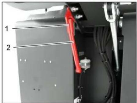
1 Hocaynpedna3haaHa
2 PpePna3Ha 1aHa
3aBbptete npedna3HaTa 3a nbHNO n3npa3BaHe HArpe nI Noctabete B Hocaya (NoCDnrypeHa).

Mona He donnyckaite B OKonHata cpeda da nonadat MToTropHo Macno,Hafta,IN3eN 6eHN. Moia na3ete noyBaTa nOTcpanhaBaiTe CTapnTe MaCJa Ona3BaKn OkonHaTa CpeDa.
Yka3aHn 3a 6e3oNaCHOCT akymyIaTOPn
Ppi pa6oTa c akymyIaTOPnTe HennpeMeHHo Cna3BaIe CnEHNrTe PpeDynpEnTENHy yka3AHN:

Cna3eaume yka3aHnma Ha akymynamopa, e YnbmbaHem 3a ynompe6a u E Ncmpykucma 3a ekcnnoamaua Ha npeeo3Homo cpecmgo!

Hoceme 3auuma 3a ouume!

Дрьхме deuama HacmpaHU om kucelenhu u om akymyamopu!

Onachocm om ekcnnoia!

3a6paHraam ce o2bH, uckpu, omkpuma ceemnHa u nyweHe!

Onachocm om pa3aJdahe!

Tbpea nomou!

Yka3ameJHa 3a6eJexKa!

V3xEbpynHe!

Akymynamopa da He ce xebpIa E Kofama 3a 6oknyk!
ONACHOCT
Onachocm om ekcnnoia!
13non3eaumcama6amepuu c nokpu-mueHa nolnoa.Ppu 3a2y6a cmeheme nokpuemuHa nolnoa.
ONACHOCT
Onachocm om ekcnlo3u!
He nocmaeune uhcmpymehmu ebpxy akymylamopume. Kbcocbeduheue u onachocm om ekcnno3u.
ONACHOCT
Onachocm om HapaHaahe!
Hukoza He donyckaumedeonup Ha pa Hume do onofo.Cnepaoma no ay Mynamophume bamepuu euaeu no- yucmeaume pbueme cu.
ONACHOCT
Onachocm om nojak u ekcnnoa!
3a6paH8am ce nyuehe u omkpum 02bH.
→ NomeeHura, e Koumo ce 3apek- dam akymyamopu,mpa6ba da ce npoeempraea do6pe,mbu kamo npu 3apekdahe ce o6pa3yeam eucokoeKcno3ueHU a3o8e.
△ONACHOCT
Onachocm om pa3jdahe!
→ Πρβκιον Kucεπινιδούme unu no κοχama da ce u3nnaekam pecn. u3mu-eam c yucma eoda.
Cne moa He3a6a6Ho da ce nombpcu nekap.
3aMbpeHomo obneKno da ce u3npe c 0da.
NoctabeTe akyMaTopa n ro NOdBpbKeTe
YpeBte oobopydban cepnHo cakymyataTOp, KOITo He ce Hxkdae OT noDpBkka.
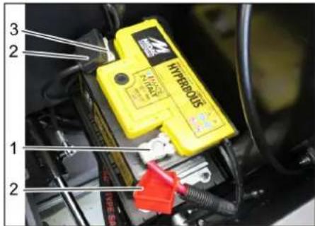
1NoIOXKITEnEHNOHOC
2 Nokpntne Ha noJIocnTe
3 Otpuataeien noHoc
→ Nocabete akymnatopa B Hocaya 3a akymnatopa.
Da ce 3aBnT 3npBO nbpKaHrTe Ha noDa Ha akymyNaTopa.
→ Μούηchata κηεma (черьен кабел)да ce nodBpxe Ha nIIOCOBnO nIoIC (+).
Ae noBbpxe nonIOchata KneMa HAMHycOBnnoIoc(-).
NocTaBeTe nokpTuTnTaHa noIIOcUte.
→ПОЛСИТЕHaakymynaTopaиNOJIOCOBITEKJEMNdaCEnpOBepRT3aDOCTaTbUHa3aUNTaCBCCMa3ka3aUNTaHaNOJOCN.
PpOBepTe HNBTo Ha TeuHocTtHa aKymlaTopa n ro KopnnpaIte (cAmO npn aKymlaTopn, KOITo CE HyxdaT OT MaKa NoDpBxxKa C KanaeTa Ha KJeTKnte).
PNEI3NBOCT
Onachocm om nopepa!
→Ppu HanbJIHeN C KUcEJIuHa aKymJa-mop peo6Ho npoepeaume HueomO ha meHocmma.
Pa3BnBaIe BCnKn KanaHeta Ha KNETKe
OTBCaKaKNeTkaDaCeB3eMe npo6a c KOHTpoNbOp Ha KInCeINH.
- KncenHaTa Ha n3uNo HanbIHeN aky Mynatop npn 20 ^ C Nma cneunqnuHo Terno ot 1,28 k/π.
-KnceHnHaTa Ha qactuH0 3apeH akyMynatop nMa CneuΦnH0 Terno MeKdy 1,00 n 1,28 kT/n.
-BBBCNUKKNKeTKNcNEUΦNHOToTe-rrnoHa KnceJINHata TpR6Ba da 6bde eHaKaBO.
PpobataOTKNCENHATAOTHOBAce BbpHEBCbuaTAKETKa.
→ПиТБьрднИСКОНBOHaTeHOCCTTДONBJINHETEKIELTKITEcDECTUNIPaHA BOdadoMapKnipOBkata.
3apeTeaKMyNaTopa.
3aBnTe kanaeTaHa KneTKnTe.
3apepeakymyatapopa
ONACHOCT
Onachocm om HapaHaahe!
→ Cna3aume npednucanura 3a 6e3o-nachocm npu 6opaeene c akymnampu. Cna3aume ynbmeahemo 3a yno-mpeba na npou3eodumela Ha 3apdHomo ycmpoicmo.
ONACHOCT
Onachocm om noepeda!
→ Akymyamopa da ce 3apedu c noxdoxo-0a0 3apno ycmpoucmeo.
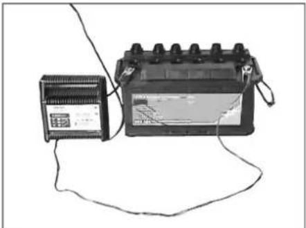
Pa3BnBaIe BCnKn KanaeTa Ha KneT-KnTe. (cMo npn akymyIaTopn C MaIka NODpBxKa)
Kaben nooxktenen noioc Ha 3apnHOTO yctpoNCTBO da ce Cbpxe c n3BODa Ha nooXkTeHNn NOIC HA akyMnyatopa.
Kaben OTPuataTeH noHoc Ha 3apHnHO YoCTPOIcTBO Da CE CBpXe C n3BODa Ha OTPuataTeHnnoIoc Ha akyMnyatopa.
→ Da ce noctabn MPekOBn Iuekep n da CE BKNIOH 3aprIHOTO yCTPOINCTBO.
3apeTe akyMynaTopa C Bb3MOxHO Hn-MaTbK 3apJeH TOK.
Korato akymyataopbTe 3apehen, 3apnHOTo yCTPOINCTBO Ce OTKaHa NpBPOOT MPekata, CneT TOBa OT akymyataopa.
3aBnTe KanaeTaHa KNeTKeT (cAmO npn akymynatOpn C MaJka NoD- dpbXkA)
DemoHTax Ha akymynaTop
OTkayeTe NnIOCHATA KEma OT MHyCOBNA NOJIOC (-).
OTkayete noJIIOCHATA KneMa OT nIIOCOBnI NOHc (+)
Ocbo6oTe HocaHTe Ha nOda Ha aKyMynataopa.
→ CbaTe aKymyNaTopa OT Hocaya 3a aKymyNaTopa.
OTctpaHete n3pa3xoDeHnAkyMylaTOp KaTO OTnaBbK cbrIaCHO BaINdHnTe pa3npoe6n.
PpOBepTe HnBToHa cnnpaHaTa TeuHOCT ndoJeTe cnnpaHa TeuHOCT △ONACHOCT
Onachocm om HapaHbaHe!
Bunau noocmaeime npedna3hama uHa2a npu no8duham peepoap 3a u3MemeHOMO.
→ N3eBpuEaume oBe3oNaCraeaHemo Ha Onachama 30Ha cAmO omBn.
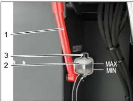
1 Hocay npedna3Ha aHa
2 Pe3epBoap 3a cnpaunHa TeuHocT
3 3aTbapau Kanak
→ПиДВИЖЕТе pe3ePBOapa 3a n3MeTeHOTO Harope n ro obe3onacete c npednA3HaTAtu aHaRa, no TO3n Bbnpoc BIXKTeB rnaBa "I3npa3BaHe Ha pe3ePBOapa 3a n3MeTeHOTO".
PpOBepeTe,daJIbBpe3epBoapa 3a cnpaUHa TeHOCmHa HauuHa DocTaTbUHO CNpaUHa TeHOCt.
Yka3aHne
HnBToHa HnBbIbAne TpR6Ba da e MExdy MapKnpoBknte Min. nMax.
→ Hnyka doneTe cnnpaHa TeuHOCT DOT, KOrTo MoKeTe Da 3aKynIe OT TbproBcKaT a MpeKa.
Ja Ce IPOBepn HNBOTo Ha MOTOPHO MACNo N da Ce DoJee MacNo OJACHOCT
Onachocm om uzeapnHe!
Momopa da ce ocmau da ce oxnau.
→ PpOBepKa Ha HnBOTO Ha MOTOPHO MTACNO Da ce N3BbpHn Hau-paHO 5 MHTN CNEI N3KIOUBAHe HA MOTopa.
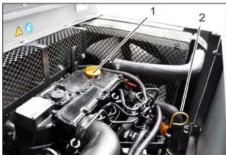
1 Kanak 3a nbnHe He Ha MacNo (Bnra-TeN)
2 Macnon3MepnteJHa npbuka
Da ce n3BaI MAcNON3MepuTeJIHaTa npbka.
Da ce n3tpne Macnon3mepntenHaTanpbka n da ce nbxHe.
Da ce n3BaMn Macnon3MepeHHaTa npbka.
OTHTaHe Ha HNBOTo HA MacNoTO.
→ ΠbXHETe OTHOBO MACJION3MepNTeHa-Ta npbka.
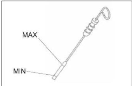
-HNBOTo Ha MacNoTo Tp6Ba Da 6bDe MeKdy MapKnOpBka, MNH" - n, MAKC".
-AKO HNBOTo Ha MacNoTo e NoI MapKnPOBkata "MnH", da ce DonbInu MOTOpHO MaCNo.
-Motopa Da He Ce nblHn Haid MapknpoBkata "MAKC".
Pa3BnHTeKe Kanaka 3a NbJIHe He Ha MacNo.
Da ce HanaHnH MoTOpHO MaCNo. BnKTe BnDa MaCNo B rJaBa TexNueCKn DaHHN.
3aTbOpTe Kanaka 3a nbHHeHa MacNo.
Ja ce n3yaka MNHIMMy 5 MNHYTN.
a ce npOBepn HNBOTO Ha MOTOPHO MTNO.
CmHa Ha MOTOPHOTo MaCNo I MacJeHnIe HnITbP Ha MOTopa IPEJNA3JIHBOCT
Onachocm om uzaapnne nopadu opeuo macno!
Momopa da ce ocmaeu da ce oxnau.
→ PnroTBeTepneMeHcBd3aMnH.6 NHTbp MOTOPHO MACNO.
→MToTopa da ce ocTaBn da ce oxnaI.
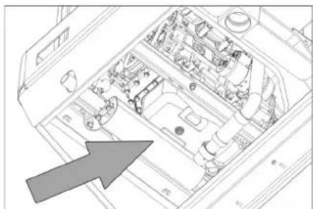
a ce pa3Bne BnHTa 3a n3nyckaHe Ha macno.
Pa3BnHTe Kanaka 3a NbHe He Ha MacNo.
Da ce n3nyche MacnoTo.
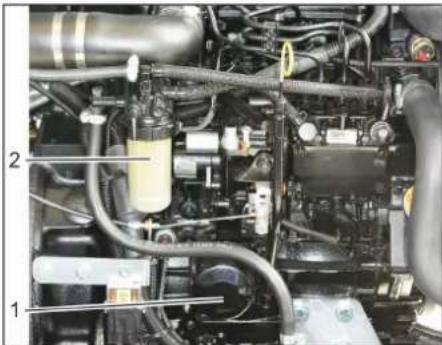
1ΦnntbP ha MacNtOHa DnBnFaTeTn
2TopinBEnΦnITbP
Da ce pa3Bne MacnHeHna qntTp.
→ NOnCTBaHe Ha MRCTO3a NOCTABRHe INNtHTNE NOBpXHOCTH.
→ Hamaxete C macNo ynTbTHEHneTo Ha HOBNA MacNeH pntTbp npdeM MOHTaKa.
→ MoHTnpaIte HOBnMaCJIeH φnITbP n IRO CTERHeTe Ha pKa.
3aBnIe BnHTa 3a HnyckaHe Ha mac- nOTO 3aEINO C HOBOTyNtBTHEnHe. BbptT MometH Ha 3aTrahe:25 Nm
Aa ce HAnbHnMOTOpHO MacNo. Bnda Ha MacJIoTO N KOJIueCTBOTo Ha nBHe He BxKTe B rnaBa TexHueCKn DaHHN.
3aTbOpTeKaNaKa3aMbHeHaMaCNo.
OCTaBeTe MoToPa Da pa6oTn npu6n. 10cekyHn.
Da ce npoBepn HNBOTO Ha MOTOPHOTo MACNo.
IpoBepKa Ha roPbHnA qntTbp
→ PpOBepeTe rOpBnHnAΦnTTbp 3a 3a-MbpcraBaHe.
→ Pn Heo6xOIMOCT NOHCTeTe RopNB HnA KOpNcHa HnTbpa, aKo Tp6Ba, CmHeTe RopNBnHnTbP.
CMHa Ha roPbHnHnΦnTbp
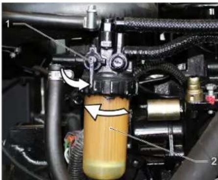
1KpaHrnpBo
2TopnbEnΦnITbp
3aTbOpTe KpaHa 3a ropuBO.
Pa3BnTe roPnBnHnΦnTbnpro CMe- HETe.
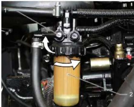
1 KpanrnpBO
2TopBENΦnITbP
YKA3AHHE
Ipedu MOHmaxa HanbInheme zopueHua unmbp c duzen.
→ 3aBHTeTe HOBn rOpNBENHPTbP.
3aterheTe ropNBnma qnTbp C BbpTMA MOMEHT OT 20Nm.
OTBopeTe KpaHa 3a roPBO.
N3nycheTe KOHde3HaTbOdaOT BOoOTdEniTEnHa DN3eNOBOTO ropuBO
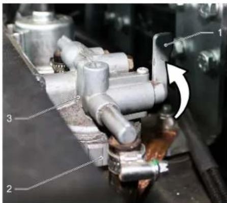
1KpaHrOpINBO
2 Tpace hacenapaTop
3BDOOTdJIHTeI
3aTbOpTe KpaHa 3a roPnBO.
Pa3BnHTeTe n 3npa3Hete Tpaceto Ha cenapaTopa.
3abuHTe TpaceTo Ha cenapaTopa.
OTBopeTe KpaHa 3a roPnBO.
PpOBepKa HVBOTo Ha XnDpaBnHOTOMacno IOnbIbAHe Ha XnpaBnHOMacno
YKA3AHHE
Pe3epoapb m 3a u3memehomo He bua a dboe noeduham.
OTbopete Kanaka Ha DnBraTeJra.
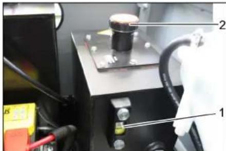
1 Macnoyka3aTeJ Ha XnDpaBnHOTo MacNo
2 3aTbapau Kaapan, OTBOP 3a NbHe He Ha MacnO
PpOBepeHnBToHaXnDpaBnHHTo MacNo BHa6nOdaTeHnHOTcTbKnO.
-HBOTO Ha MacNoTo Tp8Ba Da 6bDe Mekdy MapknOpBa ,MnH"- n,MAKC".
-AKO HNBOTO Ha MaCnOTo e NOD MapKn-POBkata,MH",da ce donbHn Xndpa-BNNUHO MacNo.
Pa3BnTe 3aTbapraunKaanKaHaOTBo-pa 3a nJIHeHe Ha MacNo.
→ NOnCTeTe Dnana3OHa Ha TbJIHeHe.
→ DOnbHHeTe XnDpaBnHNo MaCNo. BnKTe BnDa MaCNo B rnaBa TexHnueCKn DaHHN.
3aBnTe 3aTbapuua Kanak Ha OTbopa 3a NbHeHa MaCNo.
IpoBepkaHaXnDpaBnHnHaTa ype6a YKA3AHNE
Iodopbxxka Ha xudpaenuhama ype06a camo om cepu3a Ha Karcher.
a ce 6nokupa 3actonopbaaata cnpaqka.
CTapTupaHe Ha MoTopa.
→ BcunxuapBnHm MapKyu n3BO- dna ce npoBepr 3a xepMeTuHocT.
PpOBepKa Ha HnBOTO Ha oxJaXdaUTo CpeDCTBO
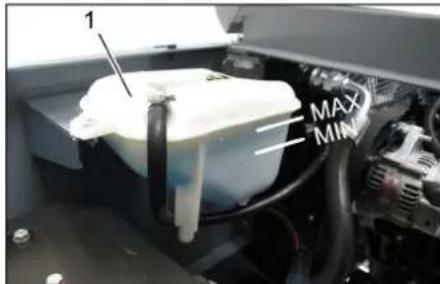
1I3paBHTeHcBd3a aHTnФpN3
→ PnpOBepTe HnBTo Ha 3aIbIbAhe npn CTyDen DnRaTeJ.
→ PpOBepeTe HNBOTo Ha 3aIbJIbaHe B n3-paBHnTEJIHnCbJ3a aHTnΦpn3. PpaBnIHOTO HNBO HA aHTnΦpn3a Tpr6BaJa e MEXdy MapKnpoBknte MIN mMAX.
IpoBepka INouchTbaHe Ha BODHOTO OXJaXdaHe INOXAaXDaHETo Ha XnDpaBnHOTo MaNo
ONACHOCT
Onachocm om u3zapareu nonapbahe!
Ocmaeeme eodnpaadamop da ce oxnaodu MUHUMYM 20 MUhymu.
HNBOTHOxJAAaataBOHaBOHOTO OXJAAHe CE npOBepBa Ha H3paBHnTeJIHnCb 3a aHTnΦpN3.BKTe InaBa ,PobepKa Ha HNBOTO HaoxJAAaata BOa".
→ NOnHCTe IaMeIInTe Ha OxJaNTeJIa. OTCpaHete 3aMbpcBaHNrTa C MeKa HETka, Bb3dYx NOI HaJraHe INN HNCO HAnraHe HA BOdaT.
PpOBepeTe MapkyuHTe Ha OXnAaNTeTnI N3BODn 3a XepMeTnHOCt.
→ NOpHCTeTe BHTnlaTopa.
PpOBepKaHaMeTAnBaJAK
CTapTupaHe Ha MOTopa.
→ NOBUNHETe pe3epBOapa 3a n3MeTeHO-TO DO KpaHOTO NOJIOXHeH.
Da ce N3KJIIOH MOTopa.
Da ce 6Iokupa 3actonopbaaata cnpaquka.
Ae noctabn npedna3HaTa 3a BnCOKO n3npa3BaHe.
OTctpaHeteJeHTteUHypobTeOT METAUNBAJK.
→ 3BaTe npeDn3HaTa 4Ha.
CTapTupaHe Ha MoTopa.
→ CnyckaIte pe3epBoapa 3a n3MeTeHOTo DO KpaHOTO NIOJOKeHHe.
Da ce N3KJIIOH MOTopa.
Da ce CmEn MeTzua BnAe
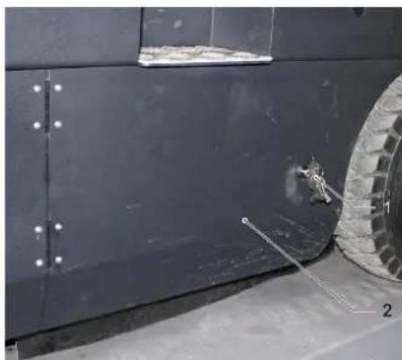
1 Kniou
2 CtpaHnHa o6JIuOvBa
→ N3HeceTe Harope pe3epBoapa 3a n3-MeTeHOTOnoNoCDnrypeTe Cnpedna3-Hata uHaHa.
OTBOpTe cTpaHnUHaTa 06nIOBka C KIHOY.
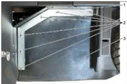
13aIbpxkaa cko6a
2 Kpunuata raika
3 CtpaHNo ynTbTheHne
Pa3BnTe KpNHTe RaKn.
→ Cbaane 3aBpkaaata cko6a.
Pa3BnHTeTe KpUHaTte raKm OT 3a-DbpxkaTaI naMapuHa Ha CTpaHnHTo yPbTHHeHne n CBATe 3aDpbKa-uaT aI naMapuHa.
O6bpeTe ctpaHnHTo ynTbTHHe HABbH.
Pa3BnTe 3akpenBaunBnHT Ha 3akpenBaHeTo HA METaUNBaJIaK N HAKIOHeTe 3akpenBaHeTo HABh.
→ CbaTeMeTaeBnA BnAeK.
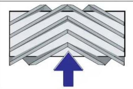
MOHTaxHo NOLOXeHHe Ha MetaunBaJAK No Nocoka Ha DnBxKeHneTo (NorIeD OTrope) Yka3AHne: Pn MOHTaxKa Ha HOBn METAu BAJIk BHHMaBaIte 3a NOLOXeHNeTO Ha KOMINKTEA YETK C YeTNa.
→ MoHTnpaIte HOBNI MTeA BANK. Tlb-6OBeTe Ha MetraUNBaNk Tpr6Ba Da ce NoCTABT B ONOPTE Ha MetraUNBaNk HA CpeUyNoJIOXHHaBanHaCnP.
Yka3aHHe: CneM OMTaxKa Ha HOBnMaTeTtBaIaK OTHOBo TpRbBa Da ce HAcTpOnpePfNeKTopbT 3a MeTeH.
PpOBepKa nHaCTpoKa Ha peΦJIeKToPa 3a MeTeHe Ha MeTuaBJIaK
→ N3KJIIOUbaHe Ha CMyKaTeJIHHa YIIOBNTeI.
→MeTaHHaMaUHnHa da ce 3akapa Ha paBHO n rnaKO macto, KOeTo e NOKpI-TO c npax nn Te6eunp Taka, ye da ce BnKda.
→ CnyscheMeTaeBaanKcIOCT3a 06CnykBaHeIroOCTabeTe da pa6oTt (ok.10ceK).
→ПовдоганHaMeTЯиBaJЯK.
KapaTe ypeHa Ha 3aDen xoI.
PpOBepepepeEeKTopa3aMeTeHe.

ΦopMaTa Ha peФЛeKTopa 3a MeTeHe TpIbBA Da O6pa3yBa IpaBUNeH IpaBObIbJIHK C WIPINHa OT 80-85 MM.
HactpoTe peΦneKTopa 3a MetHe
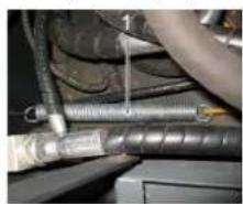
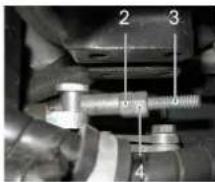
1Пукунна
2 Raika 3a peynpahe
3 KOnTparaKa
4LHaHra cpe36a
HactpoTe nIOJKeHHeTo Ha pePneKTopa 3a MeTeHe NOpCeDCTBOM peryIpaHe Ha 6oNTa 3a HactpoKa.
PpOBepepepeekTopa 3a MeTeHe.
PpOBepka HnacTpoKa Ha peFNeKTopa 3a MeTeHe Ha CTPaHnUHaTa MeTJa
→ NOBnraHe Ha cTpaHnHHTe MeTJI.
→MetaHata MaunHa da ce 3akapa Ha paBHO nIpaKo MRCTo, KOeTo e NOKpTTO C npax nn Tebeu np TaKa, ye da ce BIXkDa.
Cnychete ctpaHnHata MeTna C noCTa 3a ynpabJIeHne n octabeTe da pa60- TN np6n.10 cekyHn.
→ NOBurareHa cTpaHHTMeTIN.
KapaiTe ypeHa Ha 3aJeH xoI.
PpOBepepeepnEeKTopa3aMeTeHe.
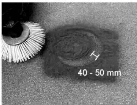
HInpoHHaHa peΦneKTopa 3a MeTeHe Tp6Ba Da 6bJe MeJy 40-50 MM.

KopunpaTe peoNKeTopa 3a MeTeHe c Dbata 60TTa 3a HAcTPOka.
PpOBepepepeKTopa3aMeTeHe.
HactpoKaHaCTpaHnHnHTe YNJIbTHeHn
ONACHOCT
Onachocm om HapaH8aHe!
Bunau nocmaeune npedna3nama uHa2a npu noeuaan peepoap 3a u3MeHOMO.
→ N38bpueaume o6e3oanacraeaHemoHa onachama 30Ha cAmO om8bH.
→ N3HeceTe Harope pe3epBoapa 3a n3-MeTeHOTOnoNoCDnpypeC npedna3-Hata uHaHa.
3aBbptete npedna3HaTa 3a nIbIHO n3npa3BaHe Harope nNoctaBeTe B Hocaya (noCnrypeHa).

1 Hocaynpedna3HaaHa
2 PpeDn3Ha 7aHra
OTBOPETeCTpaHnUHATAOBnIOBka KaKTo e OnUcaHO B rIaBa CMHa Ha METAUNBAJAK
Pa3BnTe 6-Te KpUHTa rAkn Ha CTpaHnHaTa 3aDbpKaua JAmapHa.
Pa3BnTe 3-Te raikn (SW 13) Ha npedHata 3aNbPkaaI naMapina.
→ PnTUCHETe CTPaHnUHnTE yNtBTHHeHnI DOTONKOBa HADONY (HaDINbXeH OTBOp), He da ce noJy np3CToRnE oT 1- 3 MM Do nOda.
3aterHeTe 3aBbpxKaUte JamaHn.
→Повторе операцьта Ha pyraTa CTpaHa Ha ypeda.
PbHNO NOuNCBaHe Ha fHNTbpa 3a npax
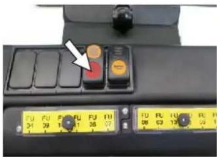
BKNIOVAHe Ha pBpHOTOnoNCTBaHe HnTpa.
PpOBepKa/cmHa HaΦnTTbpa 3a npax △PpEDyPPEXDEHNE
Onachocm om HapaHaahe!
→Ppu pa6oma nO cuememaHa qunmbypa Hoceme npaxo-3aumHa macka.Cna3aume Mepkume 3a 6e3onac-Hocm npu pa6oma c pUn npax.
→ Μούπετete φιπήtpa 3a npax c 6ytoHa 3a NOUHCTBaHe Ha φιπήtpa.
a ce n3npa3Hn pe3epBoapa 3a n3Me-TEHOTo.
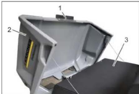
1БлokировkaHaKanakaHa ypeda
2 Kanak Ha ypeda
3 Kanak Ha qnItbpa
OTBOpTe 6JIOKIpOBKaTa,3a CEITpa3BnTE 60JIa CbC 3Be3Doo6pa3Ha dpbKKa.
O6bpHete kanaKa ha ypeHa Hanpei.
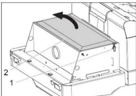
1 3akonyana,kanakHaΦnTbpa (2x)
2 Kanak Ha qnItbpa
OTBopeTe 3aKnHbHaHeTO.
OTBopeTe kanaKaHa qnntbpa.
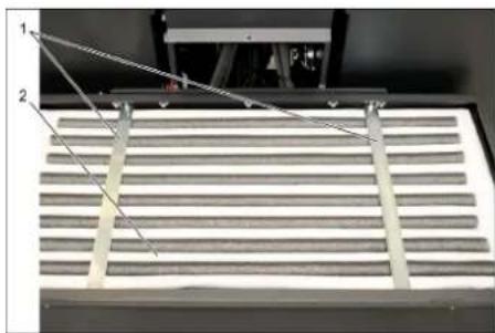
1CTpaHnHn pa3nopKn
2Филтbp3a npax
Yka3aHne
PpOBepTe fHNTbpa 3a npax, npn He-06XoDMOCr rnoNCTe ININ CMeHe-Te.
CmHaTa Ha qnItbpa 3a npax e no3BoJieHa cAmO OT OToPn3npaH cepBn3 Ha Karcher.
→ ΠοctaβeTe n 6JIokpαηte KaIaKa Ha φιπTpα.
PpOBepKa HAcTpoKa Ha KnHOBnpeMbK

KlnHOBnT peMbTk Tp6Ba Da nOdaBa npn Hanahe OT 10 Kr OK.7-9 MM.
HactpoKaTa Ha HataRaHeTo Ha KInHOBnpeMbK Tp6Ba Da ce N3BbPwBa OTOtopu3npaH cepBn3 Ha Karcher.
Da ce npoBepn n CMeHn Bb3dyuHnna

13aKnUoyBaHe
2 Kopnyc Ha Bb3dyHnHnΦnTTbp
→ CbaeneTe ctpaHnHnHaTa 06nHnObKa.
→ CbaTe KOpnyca Ha Bb3dUnHnA φnTbp.
→ CmeheTe BnOxKkTa Ha Bb3DyHnHaΦnTbP.
Yka3aHHe: MoTaxHa no3nC nO TBOp 3a npOyXbaHe HAnOly (BnK n3o6paKeHneTo).
NouctBahe Ha ceHTpo6exHnOtJeNTeI
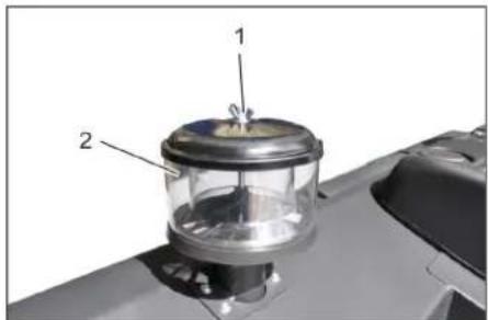
1 Kpunuata raika
2LeHTpO6ExeH OTeJInTeI
Pa3BnTe KpIyataTa raKa OT cHtpo6eKHHr OTDenHtJ.
Pa3BnTe ueHTpo6exHnOtDeHnTeJ.
CmHa HnpeDna3nteH
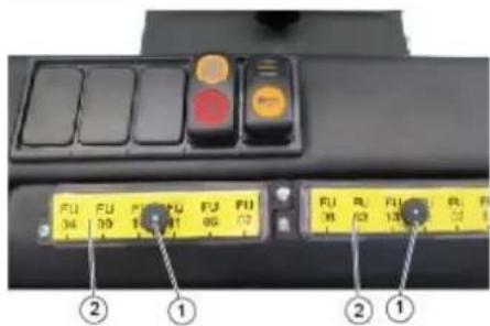
1TaiKa cHa3b6ka
2 Kanak Ha tabno npedna3nte
Pa3BnTe raKaTa cHa3b6ka.
OTBopTe KaNaka Ha Ta6No npeDna3n-TEH.
PpOBepeTe npEpa3nTEJIte.
→ CMeHete DepeKTHIe npEJa3HTEN. Yka3aHHe: N3NoT3BaIte cAmO npEJa3HTEN CbC CbUata npEJa3Ha CTOnHOCT.
Yka3aHne: IpeIpa3ntenrF U0 01 ceHa-Mnpa B OTdeIeHHeTo Ha DnraTeTn.
| FU 01 Га | авен пedingител 60 A | |
| FU 02 Кп | akson Охладител на*xидра- Влично Тмсno | 20 A |
| FU 03 Прedingио рeled Мулtnфункюналha Инданьяя | 10 A | |
| FU 04 Авагийна ламма за сbesе не сухочу | 5 A | |
| FU 05 Прedingио рeled Забавяne вов Вразимe- TO | 25 A | |
| FU 06 Осветлени в кабина- Та Чисда за настклata | 10 A | |
| FU 07 Гор�ва пома 10 A | ||
| FU 08 Реце за вруе ПрекльCBач на седал- Ката | 3 A | |
| FU 09 Осветлени OTлво 7,5 A | ||
| FU 10 Осветлени OTДяно 7,5 A | ||
| FU 11 Робъно освettingи: OTпразд (Кьси CBetлп- Ни) | 10 A | |
| FU 12 Вибрираши сисема 20 A | ||
| FU 13 Сигал за пindвожва- пес назад | 5 A |
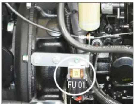
PpnooxmHaohoHaHnCTaHdaptN
PpINOxeh MeToI 3a OueHka Ha CbOT-BETCTBNETO:
2000/14/EO:Прилwxкене V
HnBOHaWym dE
NImepeHo: 96
TapaHTnpaHo: 98
IopnncBaunTe Iuca DeeCTBaT OT IMeTo n KaTO PbHOMOUnHu Na ynpabntenHn opraH.


Пьномошник NO ДOKум entaцята: S. Reiser
Alfred Kärcher SE & Co. KG
71364 Winnenden (Germany)
Tel.: +49 7195 14-0
Fax: +49 7195 14-2212
Winnenden, 2020/01/01
Uldmarkusi. ET 1
www.kaercher.com/REACH
Garantii
Uldised ohutusnouded
△OHT
Vigastusoht!
Toode: Imur-puhkija istmega
Tuup: KM 130/300 R D Classic 1.186-139

Chairman of the Board of Management
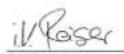
S. Reiser
Director Regulatory Affairs & Certification
71364 Winnenden (Germany)
Tel.: +49 7195 14-0
Fax: +49 7195 14-2212
Winnenden, 2020/01/01
www.kaercher.com/REACH
Garantija

Chairman of the Board of Management

S. Reiser
Director Regulatory Affairs & Certification
Pilvarotais sagatavot dokumentaciju:
S. Reiser
Alfred Karcher SE & Co. KG
71364 Winnenden (Germany)
Tel.: +49 7195 14-0
Fax: +49 7195 14-2212
Winnenden, 2020/01/01
Bendrieji nurodymai. LT 1
www.kaercher.com/REACH
Garantija
71364 Winnenden (Germany)
Tel.: +49 7195 14-0
Fax: +49 7195 14-2212
Winnenden, 2020/01/01
3araJIbHi Bka3iBKN. UK 1
3axnCT HABKoJIuHbO rcepeDo
Bnua UK 1
Tapaantia. UK 1
O6naHaHHa Ta 3anaChi YacTHHn UK 1
3nakny nocijnky UK 1
CnmbonHa npncTpoi..UK1
PpabnIbHe 3acToCyBaHHa. UK 2
YMNCHHe HnpeBaBJIbHe 3aCTOCy
BaHHa UK 2
PiiXoJnI noBepxHi .UK 2
Ppabuna 6e3nekn UK 2
Bka3iBkn 36e3neKn nД yac ekCnnyatauii ... UK 2
Bka3iBkn 3 6e3neKn B pexkmi pyxyUK 2
Pnncptoi 3 DBnryHaMn BHy
TpiuHboro 3ropaHHa. UK 2
MaunHn 3PiJIOOMHNKOM KOHTeHepa. UK 3
Pnncpi i3 3axnCHm daxom
BODIa UK 3
Bka3iBkn 3 6e3neKn iN ac tpanCnOpTyBaHnHaMunH..UK 3
Bka3iBkn 3 6e3neKn iid yac dOrnny Ta TexHicHoro o6cIyroBvBaHHaUK 3
Pn3NaueHn. UK 3
Bka3iBkn npn po3BaHTaxeHHI. UK 3
ElenmEnTu npablinHn i ykuio
HaJIbHI By3nn UK 4
306paXeHHn iDmitaIbHOi MaHn. UK 4
Pahenb ynpabnHH. UK 4
PegaJI UK 4
KohtpOJIbHI iHnIkaTOpN Ta dN-
CPIIeI .UK 5
Ipeep nooyatkom po6oTu. .UK 5
3aφikcyBaTN/BiDnyCTNTn CToH-KOBe raIbMo. UK 5
IpecybaHHn iDmitaJIbHOI MaHINH 6e3 BlaCHOrO npBoda
IpecybaHHn iDmitaJIbHOi Ma- uHHN 3 Bnachm npuBODom
BBeHnB E KcNlyatauio UK 5
3araJIbHi Bka3iBKn .UK 5
Ipebeipka iTexhihe obcnyrobyBaHHa UK 5
3anpabka UK 5
Ekcnnyataia. UK 5
Hactpoitn noIOXeHHcNdiHH
BODIa UK 5
3ayncttn npncptpi. UK 5
PepecyBaHHHa npuIaI
PiimitaHHa. UK 6
CnopoKHTn pe3epByap dny
CMITRA. UK 6
BmKHy npictpi..UK7
TpaHcnpTyBaHHa. UK 7
36epirahnH/BuBeDenHH3eknnyata
Lii. UK 7
Dorra Ta texiHne o6cnyroBaHHaUK 7
3araJIbHi Bka3iBKn .UK 7
UK7
PepioHnHCTbTexHnHoro 06cny
ROByBaHHa UK 7
PpOphiKaTHuHi po6oTu. UK 8
Dionomora y BnnaKny HenoJaOK
Texhihi xapaKtepcntu .UK
3aBaBn BiDIOBbHicTb EbponeCb
KORO CnIBTOBAPcTbA .UK

IpeepnIm 3acTocyBaHHMa Baworo npncTropo npouHTaTe
IO opRHaIbHy IHCTpyKUIO 3 EKcnNyatauii, nicra cIbO rDiTe BiIDNOBIDHO He Ta 36epexiTb II dNn noaIbWoro KopnctyBaHnA bdo nna HAcTyNHOro BlaChnka.
3araabhi Bka3iBkn
Ku npo pO3nakyBaHHi 6ynBnBnBneH noKoKeHHN Bi TpaHcNoptyBaHH, Hea HcNoBicItb npo ue Mara3n, De Bn Kynn npnaad.
HaHeceHi Ha npicpti nonepdxyBaIbHi 3nAkn Ta Ta6nUKn DaHOb BaKnBi BkazBKn Dny Be3neHoE kcnlyaTaui npictpo.
-Pa3om i3 Bkazibkamn B ciin HcTpykuii Dnra ekcnnyatau cniB bpaxobyBatn 3araIbHI npabNna TexHNI 6e3neKn Ta HOpMN dnnnonepdXeHHHeUacNHx BNnAdkiB 3akoHODaBvIX opraHIB.
3axnCT HABKONHboro cepeOBUca

MATEPIAIN ynakOBKN iIDaIOBcra nepepO6i Dnna NOBTOHORBVKOPNCAnH.NyDb NACKa,HeBKNDAIte nakyBaNbHi MaTEPIAII pa3OM i3 DOMaUNHIM CMITTM,BIDaAIte ix dNnHa nepepO6ky.

CTapi npncptoi MicTb ciHHi MaTepiAIn, kki MoKyTB nepepo6nTa nPiIraToB nepeaHi BnyHKTI npinyomByBtopHHoI CPOBHN. Tomy, 6ydb nacka, yTuNl3yIte CTapi npncptoi 3a doNOMOROIO cneiaJIbHnx CnCTem 360py CMITTA.
He donyckatn noTpannnHn H MToPHoro MaCTnla, n3eIbHorO naIINBaTa 6eHNHy B OTOuyUcpe cepedobuie. Bepexitb 3emIIO Ta yTNi3yIne BiDnpaCbObaHe MaCTnlo 6e3 uKoNn HabkONnHbOmy cepedobuIcy.
IHCtpykuii i3 3actocybaHHKOMNOHHTiB (REACH)
AkyaIbHi BiOmoCTI Ipo KOMnoHEnTn HabeHei Ha Be6-By3JI 3a aDpecoH:
www.kaercher.com/REACH
Fapantia
YKOxHi KpaIHI DiIOb yMOBn rapaHTi,Ha daHOI BiINOIBHOO fipMOIO-npOaBcEm. HenoJaKn BpoBoTI npICtpoM M yCyBaMo 6e3KoUToBHO nPoTAROM TepMIHy dI rapaHTI, kXIO BOH NBIKNKaHI 6paKOM MaTePiaJy NH NOMIKAMN BFOTOBHeHHa. Y BnnaDky HnHoi rapaTII 3BepTitbcrdo npOaBzry H NaB6JIuXh ABTop3OBaHn CepBicHNI CEHTp 3 DOKyMeHTaNbHM NiIDTBepXeHHm NOKyKn.
06naHnHa Ta 3aNaChi YacTHN
HE6E3NEKA
Uo6 yHukhmu He63neku, pmoHm i ycmaHOky 3anaChux demaneu noBuHHi eukohyeamu minbku aeMOpuzoeaHi cepiChi ueHmpu.
-MoKHa BnKOpNCToBvBaTn NmIe Te 0bnaHnHH Ta 3aNaChi YacTHNn, IIO Do3BOJIeHi DnBnKOpNCtAHn BnPo6- HNKOM. OpiRiHaJIbHe ObnaHnHH Ta opRiHaJIbHi 3anachi YacTHNn E rapaH- TiEo TORO, IIO npncTpiB 6yde npauObaTn 6e3neuHO Ta cnpabHo.
-Падьша inhфорmaця no 3anachmчactnham e ha caNTi
www.kaercher.com B po3dini Cepbic.
3HaKn y noci6Hnky
HEBE3NEKA
3anobiae npo He6e3neky,ka 6e3nocepehbo 3aapoxy ma npu3eodumb do mxxmpaem Yu cmepi.
△NONEPEDXEHH
3anobiae npo nomeuHMOxuuy He63neHy cumyaui, uO MOKe npu38ecmu do mkkuxmpaM Yu Cmepmi.
△OSEPEKHO
Bkaieka eiohocno nomenuho moKnueoi Hebe3neuHoi cumyaui, uo MOKe npu3Be-cmu do ne2kux mpaem Yu cnpuunum Mamepiabhi 3bumku.
YBATA
Bka3ieka 0do moKluoI nomHe He63neHiu cumyaqii, zo MoKe cnpuHuMu mamepiAnbHI 3bumku.
CnMBOJI Na npncTpoi
| SSS | Hebe3neka oniky ob zaporuy noeepxHIO!! Paped noyam- kom o6cnyuobyeaHnry npuna- dy cnid damu euxlonniü mpybi oxonodumcub. |
| Pobomu i3 pucstpoem cnid zabkdu npo8odumu minbku y eidnoeiedhux zaxuchux py- kauzex. | |
| Hebe3neka zamuckanhy puxlubumu demalaymu ab- momobiln | |
| Hebe3neka odepjahanhy mpaemu biD puxlubux ya- cmun. He mopkamuc. | |
| Hebe3neka nojeki. He do- nyckamu BCMokmyeaHnry na- naioychx abiO mniouchx ppeh- memie. | |
| 3amuck对外开放和0a/moc- ka po3ma7ybaHnry kpany | |
| Tochu niðomy对外开放和0mKpa- ma |
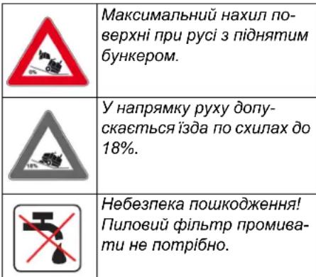
PpabunbHe 3actocybaHHa
PiimTaIbHy MaunHy npn3Haeyo DnnpocecinHoro BnKOpncTahnhy nid cac npnbipanHH noBepxOHb, HanpNKlaD, B TaKnxrany3x 3actocyBaHH:
CTOHHK
Bupo6nHi cnpuyd
TepuTopi IorictnHnx cnyx6
ToreJI
Pozdi6Ha Topribna
Tepntopitcklaicbknx npmiueHb
TpoTyapn
→ BnKOpNCTOByIe TIO nIMiTalbHy MaHInHy TiIbKn 3riINO 3 IHCTpykciio NO ekCnnyataui. ByNb-Ke iHwe 3actocyBaHHB BAaTcR He npabINbHM. Bnp6Hk He Hece BiNObiAnbHOcti 3a 3bNTKN, 3aBdahi HnpabINbHM 3actocyBaHHM, 3bNTKN 6pe Ha ce6e NlWe KopNCtBuA.
3a60pOHaETbCBAHOCHTN3MiHNB npnna.
→ΠiMItaJIbHa MaunHa npn3HaYeHa TINbKn Dnra pO6Ot Ha noBepxHx NiI-Nor, 3a3HaueHx y daHomy noci6Hky 3 ekCnnyataui.
→ PnlaM OKe nepeCyBaTcN TIlbKn nO nobepxHx, DOnyueHnx dIa BnKOpnCTAHHa NIMiTaNbHnx MaunH KepiBHNCTBOM NiINpneMCTBa a6o IxHimnpedCTabHkOM.
Raarabhe npabnlo die HactynHe: He donyckaTN 3iTKHHeHH npunaTy 3 nerko-3aIMNCUMpeoOBnHAMn (He6e3neka B6xy/noKexi).
YmncHe HnpaBnblbHe 3actocyBaHHa
3a6b0pOHHcPiD6bpaHnH/BCMOKtYBaHH BvBxOHe6e3neuHnx piHN, roPioHx ra3iB, a TakoH Hepo3BeJeHNX KNCLOT Ta po3unHHNKIB! Ce CTocyeTbc8eH3nHy,po3piXyBaiv dp6n Ta Ma3Ty, kki MOxyTB CTBoHOBaTH BvBxOHe6e3neuHi ra3n abo cymi, 3miuyuChb 3i BCMOKrTaBHm NOBITpAM, a TaKox aUeTOHy, Hepo3BeJeHX KNCLOT Ta po3unHHNKIB, OckIbKn BOH NOWKOJKyOTb MaTePiAn npncTpO.
3abopohraTbC npn6bupaHHB/BCMOKtyBaHHpeakTNBHORMeTaeBOrO Hny(HapnKnAd,aniomHIO,MarHIO,uHKy)B3'EdHaHHI 3CNJbHMn JyKHMn a60KNCIOTHMn 3acobam nJyUeHHN.
He donyckaTNIiIMiTaHHa/BCMOKtYBaHn HnanaIOuNX a6o TIIIOUX npedMeTIB.
LcH npncpii He npn3naeHO dIra 36npaHH He6e3neuHX dIra 3doPoB'peOBOH.
3abopohraetbcraekcnnyataaipn-CTPOB B3akpntnx npmuiueHHx.
3abopohraetbcrno36epirahnnyhe6e3neuHnxmicx.3abopoheno BnKOpncTOByBaTu npucptpiyBb6yxOHe6e3NeuHnxnpimiuueHHX.
He do3B0JAEb86paTu 3 co6oH cynpoBIDHX oci6.
He Do3BOJRAETBCIaTOBxATN/TaHTHyTN a6o TpaHcNoPTyBatn npEaMeTn 3a DO-nOMorO DaHOrO npCTpO.
PiiXoJaui nobepxhi
AcbabT
Ppomncnoi niDnorn
CuyilbHa (HaMbHa) niDnora
BetoH
BpyuataKa
IpaBnna 6e3neKn
Bka3iBkn 3 6e3neKn niq yac ekcnnyatauii
→ Paped bukopumannnnepeipme Hanexku cma ma 6e3neky npucmpo ma obadha. Kaio obadHaHna 3haxodumbcy He6e3doaHHMy cmahi, U0zo He moXha buKOpucmoeyama.
Y pa3i eukopucmaHH npucmpo y he6e3neuHdiHui (HanpuKnad, 6en30koNoka) Heo6xioH oompumyeamcua biodoHux icmpykuu 3 mexhiku 6e3neku. 3abopoHeHO eukopucmoeyamu npucmpiu y 6u6yxone6e3neuHX npumiuueHHax.
HEBE3NEKA
Hebe3neka mpaemybaHHa!
→ He eukopucmooyamu npucmpiu 6e3 3axuchozo daxy e 3oHax, de ichye He- 6e3neka nadoHHn ppeMemie Ha onepa-mopa.
Kopucmyeaunouhen bukopucmo- eyamnpucmpiyybiinobidnoihocmi do ihcmpykui.Boha noeunha epaxoebyamu ymoeu micueoemni qac pobomu 3 npucmpoem Heo6xioHO 3eepmamu yeaay Ha mpemix oci, oc0bneoHa di meu.
→TakoxcnidompumyamucacixnpaBun i Hopm cmocobmo pahcnopmhux 3ac06ie.
→Ipeod noamkom pobomu onepamop nouehen nepekohamuc8 momy, 06ci 3anobixhi npucmpoi 3haxodmbcna Micui i npauoiob HanexxHm U-HOM.
→Onepamop npucmpoHece eidno-eidaNbHicmb 3a 6uHKHeHH HeuaChux BuNaAdKie 3a yacmIo Hux Iioeau abo MaHa.
Cmexumu 3a mum, uo6 onepamop hocu8 uinbno npune2nui oya. HocumuMiHe 63ymmra yHukamu Hocinna eInbHOO ORAy.
→ Pēpeo noyamkompuyx nepeepumu Mepmey 3ohy (HappuKnaD, Ha Hare-HicMb dime). 3a6e3neyu mu docmamHiou o2nro!
He moxha zanuwam npucmpiu 6e3 Haanay niac pobomu momopa.Ob Cnyooyoumy nepcoany do3eOnmbca zanuwam npucmpiu minku nicna mzo, kdoueyn 6yde 3ynuHeno, npucmpiu 3axuueenu iid bunaekoo nepemueneHH i KIOU eunrmaui.
Ulo yHuKHymu HecaHKuioHOeAo2o EukopucmaHnI npucmpoIO cnId eUImaMu KJIIOU.
→ Ppucmpiu MaE eukopucmoeyamucocobamu, uo npouuIncmpykmaxuoo 0o0o uo2o eukopucmaHHa 6o nIdmeepduu CBOI 3dibnocmi dna ocbnyooyeAHn npucmpo, a makox ynoeHOBaxHe eukopucmoeyamu uo2o.
Lijnpucmpiu He npu3haueHu dnaeukopucmaHnIOdbMU (BKNIOUauOduMeu) 3 O6mKeHUMo fI3uHUMu, cEHcOpHUMu a6o po3ymoBum 3dAmHoCmru a6o 3 iOcymHicMn doceidy u/ a6o iOcymHicMn 3HaHb, 3a eunrkmOBunaKie, KOnu 3a HUMu cmexkmb iNoiDaNbHa 3a 6e3neky oco6a 60HU Odepjyomb bId He bKa3iBu no 3acmocyeaHHIO pucmpo.
Heo6xioHo cmexumu 3a dimbmu, uo6 eoHu He apanu i3 npucmpoeM.
Bka3iBkn 3 6e3neKn B peKmipyxy
HE6E3NEKA
He6e3neKa HeuacHo2o BuNaDky, He6e3neKa yUkoJxHnHa!
Ⅲeudkicmb nepecybaHna noBuHa 6ymu eioBIOHO do omouyOux yMO8.
Hebe3neka nepekuadHn npunady Ha 3aHaado Kpymux cxunax.
Y Hanpmy pyxy donyckaembcj i3da no cxunax do 18%.
He6e3neKa nepekuOaHHa Hecma6inbHomy rpyhmi.
→Доэгясьа repemiama npunaad minbku ha miuhi niocmaeui.
He6e3neKa nepekuadaHn npunady npu benuKomy 6iHOMy KpeHi.
→ Y haprmaKax, nonepuehux do haprmaKy pyxy, donyckaembcra nepecyeaHna anapa-ma minbku no cxuTAX do maKc. 10%.
Pnucpto 3 dBnHyhamn BHyTpihboro 3ropaHH
△OepeKHo!
He6e3neKa mpaamyBaHHa!
Buxid a3ie He noBuHe 6ymu 3a6noko-8aHUM.
He haxunmucdo buxlonnoo omeopyi He mopkamucdo Hb02o (He6e3neKa oniky).
He domopkaimec u He hepimbc3a npueoohu deuyh (he6e3neka oniky).
BuxnonHi 2a3u ompymHi ukiDnei
dna 3dopeo8,ix 3aboponeHo eduxamu.
→ PicnB EumukHn deuyno oepmaembc u3-4 ckyhdu 3a ihepuieo. B ueyac cnio 3anuwanucn no3a 30ho npu60da.
MaunHn 3 niDnOMnKoM
KoHTeHepa
HEBE3NEKA
He6e3neka mpaemy6aHnHa!
NiD yac po6im 3 niDioomHukom KOhmeu-Hep Heo6xioHO noEHiCmIO niDhamu ma 3aqiKcyBamu.
Bukohyeamu 3axum minbku 3308hi He63neuhoi 3oHu.
Pnucpii i3 3axncnM daxom BOia
NOBIDOMJIENHRA
3axuchu dax (onui) 3a6e3neyu 3axum eodia bi nadiHHKpynHux npedMemie. Aine H He moke 3axucmu npu nepeepmaHH!
Bka3iBkn 36e3neKn niD yac TpaHcnopTyBaHH MaunHH
3eepmamu yeay Ha enachy macy (mpaHcnpma haa) npucmpo no ndacmpnO ppaHcnpmyeaHna Ha mpumaia 60Ha mpaHcnpmhux 3acobax.
Pio yac mpaHcnopmyaHa npucmppoi biOcHamu KneMu aKymyamopHO6a-mapei ma HadiuHo 3akpinmu npu-cmpiu.
Bka3iBkn 3 6e3neKn niD yac DOrnAy TaTexHOro 06cnyroByaHHa
→ Paped ouuueHHm i npoeedeHHm mexHicnoo ocbnyoeyeaHn npucmpo, 3amHO demanea a6o hcmpoobAHHa iHui cyHKui, npucpii cnid buKnOohmu ma buHarnmu KIOU.
Ppu pobomi 3 eenekmpuuchno ycmahoeKOIO Heo6xioHO eio'edhamu akymynarmopHy bamapeio.
→ He do360jIembca yucumtu npuna3 6o8aHO2o wnaHea a6o cmpyMeHem 6odu nio bucOKUM muckom (He6e3Neka KOpOMKO2O 3aMuKaHHra ma iHuux nowKoXKeHb).
→ Pemohmhi pobom mojymnb npo8odu mucra nuwe aemopuzoehumc cepi-chumu cnyx6amu abo cneuianicmu yui cfepi, kki o3haoumehi 3 ycima baxnubmu npabunammu mexhiku be3-neku.
→Poobumu nepeepky ha npedmem 6e3neku y biiohoHocmi do iioxmuceux dupekmue nra hecmaiohaphux npucmpoi, uo bukopucmoeyombcy npomucnoocmi.
Po6omu 3 npucmpoeM Heo6xidHO 3a-6kdu npoeodumy cneuaJbHux nepayamkax.
Pn3HaueHn
Maunha, uo niDmitae, Hanpabncre cmTTB6eNocepEnbO B pe3epByap dna 36opycmTTA.
-ObepToBn BaI, 10 NiIMiTae HAnpaBIIe CmTTI npRA MO B pe3epByap IIN36OpY CmTTI.
- BiHa uItka niDiMaTc Kytu KpaI nobepxhi, 0o NiDiMaTeBcra, i DocTaBncreMiTTB 3OHy po6Ot BA, 0o NiDiMiTae.
-Дpi6HnI NJI BCMOKTyEcBcMOKTyBaJIbHm BEHTNJaTOpOM Yepe3 φiJIbTpДЯ NJIy.
Bka3iBkn npn po3BaHTaXeHHI
HE6E3NEKA
He6e3neka mpaem ma nowkoxdxeh!
→ Ppu eanmaxKeHHi cnio 3eepHymu yeay Ha bay npucmpoio.
→ He 3acmocoeyamu eunkoeuHaeaHmaxyea, ockinbkn npucmpiu npu uboMy moKe 6ymu nowkodxeno.
PonopxHbara (6e3 MOHTaXnX 920 kg* KOMJIeKTIb)
- 3i BCTaHOBHeHM MOHTaXHIM KOMJIeK-TOM Bara npICTpO, BiIOBjIDHO, CTAc ue 3NaUHiI.
→ПиЗаВаHTaXeHHi npIcTpOu BnKOpNCTOByBaTn BiIIOBiDi CXoHNi a60 KpaH.
→ PnBVKOpNCaHHcXoJeHb CnI3BepHyTN yBary Ha HAcTyNHe: DopoxHi npocBt 70 MM
EnemEny npablinn i yHKioHaIbHi By3nn

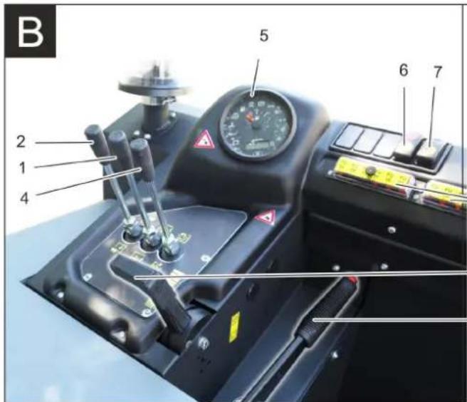

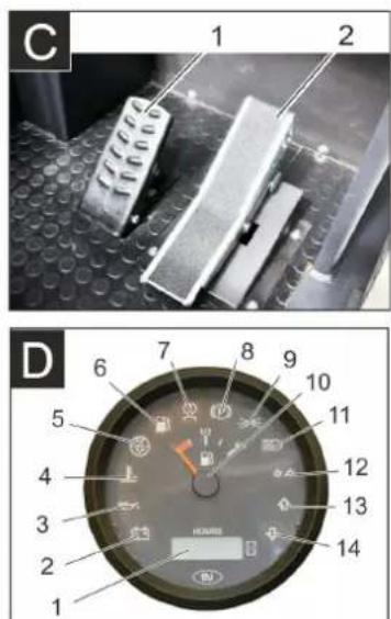
3o6paXeHHn iDmitaIbHoI MaunHn
MaJIHOHOK A
1 3amok 6aka
2 CnDinHHa (3 KOHTaKTHM nepemNkaayem cnDinHHa)
3 KepMoBe KOleco
4 BiDcHTpOBm cenapatop
5Блokувань кршкп псстpo
6 KpnuKa npncTpoH
7 BiuH iuTkn, npabopuy
8IpeepneKoIeCo
9 BxidnnoTbipBaNy, 10 niDmitae
10 CtiKe Micue KpInnHeHHa
11 3aBODcbKa Ta6nUka
12Поблесковий Маячok
13 Kpnuika npncTropo cnpaBa
14 KpnuKa, npaBOpuy
15 3aŋnii kɔkuyx
16 3aHHe KOleco
17 Kpnuka, nibopyu
18 Kpnuka 3niba (Kpnuka DnryHa)
dOdaTKoBe yCTaTkyBaHH
Peped noaTkom po60tn
3aΦikcyBaTN/BiDnyCTNTN CTORHKOBe rAJIbMO
BidiNyCTHTN CTOrHKOBE rAJIbMO,HaTNCkyOuN npuCbOMy Ha neJaIb rAJIbMa.
3aqiKcyBaTN CTOHKOBe rAInMo,HaTnCKyOuN pN Ucbomy Ha neJaBraIbMa.
IpecyBaHHn iMmitaJIbHoI MaunHn 6e3 Blnachoro npNbOda
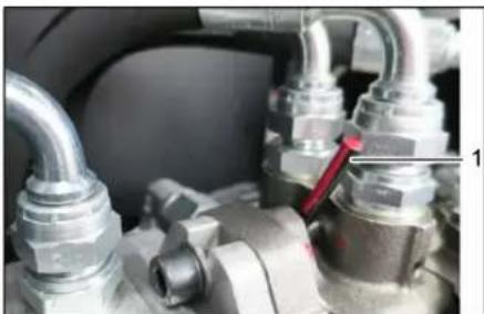
1 Bepxhe noJoxKeHHa BaxeJe BInbHoro xOdy - npucpiMoxHa nepemiuatn
BikpnKoxkxDnHyHa.
→ NObepHytn BaxeIb BiJbHoro xOdy (uepboHn) y BepxHe noIOKeHH
YB4A
He donyckacmbca nepecyeamu Mauunhy, uo niomimac Ha eenuki biocmahi ma wbuode, HIX 10 KM/4.
→ NicnnepeMieHnnoBepHyn Baxinb BinbHorO XoDy B NOaTKOBe noJoxKeHNr.
IpeceyBaHHn niIMtaJIbHoI MaunH3 Bnachm npNBODOM
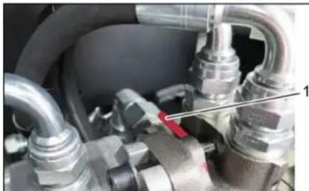
1 HnKHe noJoxKeHH BaxKeI BiJbHoro XOdy - npucpi roTOBn do nepeMiueHHa
πicn nepemiueHHMaunH BilbHni xi ndpabniHoro Hacoc a NOBepHyTN 3HOy HAnpMy rOuHHNKOBoi CTpiKn Do ynpoy.
BBeHnB Eeknnyataciu
3araJIbHi Bka3iBKN
→Ipeedeknnyataueio npoHTaTNO ciHK 3 ekcnnyataii Bnpo6Hnka npi- cpoIO i oco6JnBO npHnTo DO yBarn Bka3iBKn 0do 6e3neKn.
BctaHOBNMaHHy,IO NiIMiTae,HapibHI NOBepxHi.
BHTaHryTN KIOU 3anaIOBaHHra
3aφikcynte cTOrHOHy rAJIbMiBHy cnCTemy.
Ipebipka i TexhiyHe 06cnyroBybaHHa
UoJeHNo nepei noaTkom eknnyatauii
→ IpeBipuPiBeHb 3aOBHeHH na-NiBHOrO 6aka.
→ IpebeipntPiBHeMb MaTnua y DnBryHi.
→ NepeBipNTPiBHe3aONOBHeHHKOMneHcauiHoro 6aUka paiaTopa pIDHHOO OxOnODKeHHA.
→IpeBipNTn BAN, 10 NiIMrAe i6iHi 1uTkn Ha 3HOuYBaHHa HArBHiCTb CTpiHOK, 10 HAOTAJNC.
→ NpeBipNTKoJecaHaHaeBHicTbCTpi-OK,IOHAMOTAJNCR.
→ Penebipntu BIDueHTpOBN cenapatop Ta nobITpaHn FInbTp, npn Heo6xIdHOCTi ONUCTNTN.
→ Ipebipntn CTan BCix enemehtib ynpabJIHH.
→ IpeBipTu npuaHa npedMeT nou-KoJKeHb.
→ BnKoHaTn YIuSeHnHnΦiNbTpY dnnnny 3a DOnOMorO KHOJIKn YIuSeHnHnΦiNb- Tpy.
BkaibKa: DoknaHWe nB. po3in "Dorra Ta texHicHe 6cnyroByaHHN".
3anpaBka
HE6E3NEKA
Hebe3neka 8ubxy!
Heo6xioHO uKOpucmooyamu nuwe mou mun naHbO20, 0o 3a3Haeyu y ihcmpykuii 3 eknnnyamaui.
3a6boponembc3appaKaMaunuH6 3akpumux npumiuenHHX.
→ 3a60pOHaembca naiHH u po3eedeH H eikpumoo BOaHIO.
→ Cmexme 3a mum, uo6 naneuho He no-nadano Ha zapayi noepxhi.
→ Πηρεβίπιν εΜΗICTβ παλίνα no iHπκa-Topy pIBH naJIbHOrO.
BmKHyTN DBnHyH.
BIDKpTN KpnuKy 6aka.
3anpaBnDn3eJbHe naJbHe
Bnteptn nannBO, 10 nponnoCn, n 3a- kptn Kpuuky 6aka.
Ekcnnyatauia
Hactpoitn noJoxeHHcuiHHBODi
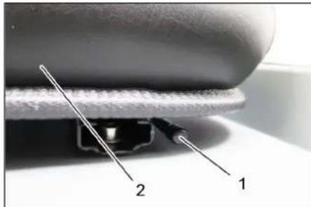
1 Baxinb perynboaHHcuiHH
2CnDHHBODI
→ Notarynt y6ik Baxinb perynioBaHHcNdiHH.
→ IpecyHyTu CnDInH, BiDnyCTTuBaXjIb i DaTu Nomy 3aΦikCyBaTncr.
→ NepemiuueHHm cnHnBnpeD/na3aI nepeBipuTu Ioro pfikcaio.
3anyctnt npncptpi
BkaibKa:PpnaOcHaueHm KOHTaKTHoIO HactnIKoIO CndHH. Ppi BCTabaHHi 3CndHHBOID npncpti BiKnHouacTbcra.
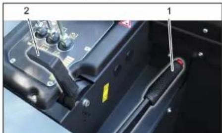
1CTOHOHnIraJbMa
2 PeryIIOBaJIbHnK YnCna oBeptIB DnBryHa
3aHnMiCneHa cnDinHIn onepaTopa.
3aφikcynte cTOrHOHy rAJIbMiBHy cnCTemy.
→ ΠepeCyHyTn BnepeIHa 1/3 peryIIO-BaJIbHnK Yncna OeptiB DnBuYHa.
PonepeDHe nporpibHn
BCTaBtN KJIIOU B 3AMOK 3aJaJIeHHA.
IpeBecTn KInOu 3anaIeHHa B noIooXeHHa, CnpaJIb po3xapIOBaHHa". 3aropitncn lamna nonepedHboro nporpiBaHHa.
3anyctntn Dnryh
→ДяЗanyckyДВИryHa Heo6xioHnHaTnCHyTN Ha ndaJIb ralbMa.
Toro, k lamna nonepedhbo nporpibaHH 3rache, o6epHyTN KnOy 3anaeHHB NOJIOKeHH. II".
→ Picra toro k npnla3a npauoe, BiNyCTHTN KIOU 3aJIIOBaaHH.
Bka3ibKa: He HataNcKaTu Ha cTapTepe 6iNb-ue 10ceyH. Peped noBToPnHM BkIIOyeHHaM cTape pOeKaTu npHaami 10ceyHd.

IpeecyBaHnHa npnadi
1IeanaIraIbMa
2 Pediakcelepatopa "Pepehni xi
3 Pediakcelepatopora "3aHni xi
→ PerynloBaIbHnK Yncna OeptIB DnBryHa nobHcTIO nepeCyHyTN BnepeD (Po-6oHe YncNo o6opotIB).
HaTnCHyTu Ta yTpmyBaTu neaIb raIbMa.
BidiNyctnte cToaHkoBe raIbMo
IxatnBnepe
Kuio nIdmitaIbHa MaunHa He BnKOpncToBcYbcra npOTAROM TpNBanoro yacy,doataKOBO cnID DotpmyBaTNC:
3amHHTMOTOPHE MACTNJIO.
→ Pn YekahHm Opo3iB cnYCTNTN BODy DnToro, 0o po3nnraio i nepeBipntu, nIOcHTb aHTnOp3ny BOdi, 0o oxoJNOJkyC.
→ NOnCTnMaunHy, 0o nIdmita3cepeHHH 3OBHI.
Bi'ειητι Κλεμησι Ακυγήτορθοῖ 6a-tapei.
AkymyIaTOpBAPTo3apdNtAn,aNOTOM cnid 3apdKaTH np6n. KOKHi DBaMciu
OorJaTaTexHiYe 06cnyroByBaHHa
3araJIbHi Bka3IBKn
YBATA
Hebe3neka nowokkeHHra!
→Πιούου φίπυmp προμεμαμη He nɔ-mpiδHo.
Pemohmipobomumoxymnbnpoobumucnueaemopuzo8anmu cepicHumu cny6amu a60 cneuiiancamu yui cpei, kci 03naoumehi 3 ycima eaxnubmu npabunammu mexhiku 6e3neku.
→Ppucmpoi,uo eukopucmoeyomcbc KomepuuHo y eidnoeHocmi do Micueux Bumoa, nidaaomb npoeedeHHo nepeepku 3 mexhiku beaneku 3iaho VDE 0701.
BcTaHOBnMaunHy, 0PiMItae, HapibHni nobepxhi.
→ Knou 3anaIOBaHH NOBepHyT B No3uio "0" i BNTaHyT NOro 3 3Amka.
3aΦiKcyIe CToHouHy rAJIbMiBHy CNCTEmy.
UH
OBEPEXHO
He6e3neKa nowkoDeHHH!
→ He do3e0bma cyaummu npunad 3 8o0ra0o wnaea a6o cmpymehem 8odu nio bucokum muckom (He6e3neka KOpomko2o 3aMuKaHHma iHux nowKo0xeHb).
UHnHn anapata 3cepeHHn HHE6E3NEKA
He6e3neka mpa8MyaehnHa!
Odaume 3axuchy macky npomu nuny i 3axuchi okynpu.
→IpoTePtn anapat raHuyipkoIO.
O6dyTu anapaT nobITpM niD TnCKOM.
UHnnaapata3OBHI
OuHCTHTn anapat, BIKOPNCTOByoHn Dnla 0BOrO BOIORY raHcy, IpocOeHy Cna6kM JyXHM PO3HNOH.
Bka3iBk: 3a6b0pOHaETbcra BnKOpNCaHH aRpeCNBHX MmHNX 3ac06iB.
PepioHnHCTbTexHIOHO6cnyroByaHHA
Bka3iBka:JIiHnBnKpo6OuXrOINH NOIbOMJIe nPo MOMENT npoBeDeHHaOBcny-ROByBaHH.
TexHie He6cnyroByaHHn, 3diCHIOCTbcra KIncHtOM
Bkaibka:Bcipo60tn3TexHnHOro6cnyrobybaHHa 36oky kIneHT noBnHH npOboDNTnc KBanlqioBaHm qaxibcem. B paziNotpeBn B 6yNb-kynn MOMENT MOXHa 3BepHyTNCnNo Donomory Cneuii3OBaHy ToproBeIbHy opraHiauio fipMn Karcher.
UoJHeTexHicHe 6cIyROByBaHHa:
Pepebipu npieh3anOBHeHH naIINBHO 6aka.
→IpeBipuPiBeHbMaTnua y DnHyHi.
→ IpebipntPiBHe3aNoBHeHHKOMneHcauiHoro 6aKa paiaTopa pIiH-Horo OXoJIoDxKeHH.
→ Ipebeipntn BAN, 0o Niimtae i 6iHy HtKn Ha 3HOuYBaHHa HArBHiCTb CTpi-OK, 0o HAMOTaJIcR.
→Ipeebiptnn naibBnH φinbtp.
→ Ipebeipu NT BIDeHTPOBn cenapatop Ta nobITpHn FInbTp, npn Heo6xIdHOCTI ONUCTTu.
→ Ipebipntu CTAH BCIX eIeMeHTIB ynpabJIHH.
→ IpeBipTu npnaHa npedMeT NOI-KoJKeHb.
LToNkHeBTEXHiyeO6CnyroByaHHa:
OuHCTHTB OBOJHn paiaTOp.
OuHCTnTn rIpaBniHm MacJHn paiaTop.
→ NpebipntriipabniHy yctahOBky.
PpeBipuPiBeHb rIpaBnHoroMaCTUa.
→IpepeipntpiBeHraBmIBHOiPiHN.
→ ΠepeBipu yuiinbHOBaBnHn nHa 3HOseHcT Ta npn Notpe6i 3amHInT.
→ Πepebipu i 3maCTnKpnu KpEepByapy.
TexHne 06cnyroByBaHHKoXHi 50 roDnH po60Tu:
→ Cnycnttu BDOy 3 BOOBIcTIuHnka (JN-3eJbHn DBNrHy).
TexHne 06cnyroByBaHHaCTnH, 3HOuyOTbc:
3amHITb yuINbHIOBaIbHi nHaKN.
BiperynIOBATn a6o 3amHHTN 6iHi yIbHeHH.
3amHItbBan,0nNiDmitae.
3amHtB6uH uITKN.
Bka3iBa: DoknaDiHne dNb. po3di "TexHiHHe 06cnyroByBaHHa".
TexHne 06cnyroByBaHH, 3dHcHcTbCnK6oO 06cnyroByBaHH cNoKBaivB
BkaizbKa:ДЯЗБЕРЕЖENHa Ra paHTiHne OBCnyROByBaHHa Bci po6oTn 3 texHINoro INpOΦiAInaTKuHoro OBCnyROByBaHHa npOTAROM rapaHTiHoro nepioy noBHHI npOBODITNcBnOBHOBaKeHO cepBicHO CnyK60O pIPMn Karcher BiINOBiDHOdo 6poUpyn NO texHInHomy OBCnyROByBaHHO
O6cnyroByBaHHy uepe3 50 roHn po6oTn:
→ 菲西泰赫尼哈克布纳CINBHKOHyBaTN BIDNOIBHO DO φoPMyIpyTexHIO ORNAYCEPBICHO CNYK6N.
Texhne 06cnyroByBaHHn nicna 250/ 500/1000/1500/2000 rOdnEcknnyatau:
TexHicHe 06cnyroBvBaHH CnID BnKOHyBaTN BiNObiINO Do opMynpTyTexHiHOrO orJMy cepBicHOI cNyXbN.
PnpoiakTuHi p6oTu
Iirotobka:
BCTaHOBHTMaHHy, 10 niDiMiTae, Ha pIBHi NOBepxHi.
→ Knou 3anaIIOBaHH NOBepHyT B No3uio "0" i BNTaHyT NOrO 3 aMka.
3aφikcyTe cTOrHOHy rAnbMiBHy cnCTeMy.
3araJIbHI Bka3iBKN 6oO 6e3neKn△HE6E3NEKA
Hebe3neka mpaemybaHnI
3a8xdu npu nIDHamy pe3epeyapi 360py cmimma cmaHOBIOBamu 3ano6ixhi umaHau.
Bukohyama 3axum minbku 3308hi He6e3ne4hoi 3oHu.

1 Tpmaay 3anobixkhoi wtaHn
23anobixhna shaHra
BiiKHyn HabePx 3anobixHy tTaHry dIa cnopoxkHeHH nIHrToPo 3epByapy i BCTaBHTIy TpIMaH (3anobixHni)

BydnaCkA,HeDonyckaTe NOTrpannHnMoTOpHnx MaCTnI,Ma3yTu,IN3eJIbHOrO naJINBaTa6eHNHy B HABKOINHe cepedobuie. Byd naCk, 3axuaiTe rpyHT Ta ytunizYe BinpaBoBaHI MaCTnla, He 3aWKoJxuyOn HABKOINHbMy cepedobuIy.
Bka3iBkn 3 texhikn 6e3neKn 0do akymyIaTOpIB
Ppi p6o3 akymyIaTopamcn iD oToPmMyBaTnCnHAcTyTHnx nonepdKByBaIbHnx BkazBOK:

Dompumyeamucr ekazieok Ha akymnamopi, 8 iHcmpyku3 KopucmyaHa ma y noci6Huky 3 eknnyaamaui npucmpo!

Hocumu 3axucm dny ouey!

He donyckamu dimeu do enekmponimy ma akymnopie!

He6e3neKa 8u5yxy!

3abopohembpc03e00HH eikpumozo 02HIO,ickPINHc cmeOpenhH eikpumux dpeen ceimna ma naninHn!

Hebe3neka ximiuhux onikie!

Tepu donomozla!

PonepeOxyeAJIbHe MapkyeaH-Ha!

Ymuniziaj!

He bukuadamu akymyarnop y KOhmeHep dna cmimma!
HEBE3NEKA
He6e3neKa 8u6yxy!
Bukopucmoyeamuminbku6amapei3 3axuchum Hakpumm noniocie.3axu- che Hakpmm e pasi empamu 3amihu mu.
HE6E3NEKA
He6e3neka 8ubxy!
He Knaemu Ihcmpymemu a6o nodhi npedmemu Ha akymyarnop. He6e3neKa Kopomko0e 3aMukahn u eb6xy.
HE6E3NEKA
Hebe3neka mpaemyeaHnHa!
→ He donyckamu konhmakmy paH 3i cBuHueBmu enEmeHmAmu. Iicnpaobim 3akymyramopm 3a6xdu Mmu pyku.
HEBE3NEKA
Hebe3neka 3a2opHHn u budyx!
3a60pOHaembca naiHH u po3eDeH H bdkpmo2o 80aHIO.
→PumuueHHy, ykomy 3apxiaombca akymnamopu, noBunHe do6pe npoeimpuoamucm, momy npu 3apxdui eudinemcbc a3, uo neko bubyac.
HE6E3NEKA
Hebe3neka ximiHux onikie!
→ Ppu enyuehnbi puzkie enekmponimy oqi a6o Ha ukipy npommu benukoio kinbkicmo yucmoi bodu.
→PiCnya0o HeaauHo 3eepHymucdo nikapra.
BpydHu o8e 3anpamu.
YcTaHOBHTn akymyIaTOp i nIDKIOHHTN noRo
Pnncpi cepinHO OchaueHO akymyIaTOPO 6batapee, 0ne He 6cnyroByeTbcra.
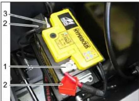
1No3HTNHBHNOJIOC
2ПОЛЮСМКOBNAЧOK
3 HeraTnBn noJoc
NocTabuNTn akyMnyTOp y TpMaay akyMNyTOpa.
3aTn TpMaHi Ha dHi akMyIaTOPHOI 6atapei.
→ПлкючNTN NOIOCHNI 3aTNCaU(YepeBOHNI Ka6JIb)do noJIocA (+)
→Πικλίουητινούσχη 3aικκαγ Φοῦνος (-).
YCTAHOBHTN KOBNAKNIEM.
→ ΠepeBipu, uH aHdiHo 3axuac MaCTNUIO NOIOCU akMyTTopa Ta KJEMN.
IpebeipnpiBHe eJekTpOiTy B akymjTOpHoi 6atapei Ta BiKopekTyBaTu NOro (TiNbKn B akymjTOpHnx 6atapex, 10 He NOTpe6yOtB TexOcnyroByBaHHa 3 npobkamn akymjTOpHnx eemeHTiB).
OSEPEXHO
He6e3neKa nowkodxehnHa!
Bakymnopax, yaki zanueaembcra Kucnoma, cnippeaynpno nepeepmu pieeHb piuHu.
BnBHTNTBcipno6knakymyraTOpHnx eIeMeHTIB.
KNCNOTOMIPOM B3AHTn npo6n 3 KOxHOrO enemeHTa.
-ⅢiNbHicTb eNeKtpOnity NoBHiCTo 3apxJKeHO rAkyMylrTopa DopIBHoE1,28 K/π npu Temnepatypi 20°C.
-ⅢiNbHictb eNeKtpOnity YactKOBo 3apRJaKeHOrO aKymyIaTopa DOpIBHIOE BiD1,00do1,28Kr/II.
-Y BCix enementax iinbHictb eek-TPonity noBHHa 6ytn OndaKoBOIO.
PpO6n eneKtpoJITN BUNHTB Tk cami enemeHTN.
→ПиЗанадTo Hn3bKOMy pIBHi piINHn 3aJIHTN B ENEMENTn DnCTnIbOBAHy BOY DO BiIMtKN.
3apnAkyMnyTOp.
3aBHTn npo6Kn akymyIaTOPHX enemehtB.
3apnntaakymyTOp
HEBE3NEKA
He6e3neka mpaemyabHnI!
HE6E3NEKA
Ppu pobomi 3 akymyramopamu cnid dompumyamucn npabun mexhiku be3neku. Dompumyamucn iHcmpykui 3 ekcnlyamaui bupobnka 3apdHO20 npucmpoio.
He6e3neKa nowokxeHH!
3apxamukymnop minbku 3a donomooi eiohoiaHO2 3apdHO2 npucpo10.

→ BnHTn Bc np6knyTOpHnx eMeHTB. (TINbKn dNn akymyIaTOpIB, 0o He 06CnyrobyIObc)
3'ειHαπιKa6eβb(+)3apAηHOro npi-CTPOIO 3no3nTnBnM nOJIcOM aKMy-ⅡrTOpa.
3'εdHaTn Ka6eB (-) 3apAHHoro npi-CTPOI 3 HeaTINBHIM NOnHOCM aKMyJrTopa.
BCTaBHTn 7TeNceBHy BUNky y MepeKxy iYBMkHyTN 3apAHN pncTpI.
→ AkymyIaTOp cni3apJkaTu 3apJHUM CTPYMOM 3MiHimaJIbHOO CnHO.
→ПиязардкakymлтopaBID'EDHyBaTN3apdHn npctpi cnoatky BiDМepeki,NotIMBIDakymltopa.
3aBHTn npo6knyakymyIaTOPHnx enemHe. (TINbN DnA kMyIaTOPiB, 0 He o6CNYROyIOTBc)
BnHrtn akymyIaTOpHy 6aTapeo
BiiKIOHHTN NOIIOCHNI 3aTnCKaY BiD nOIIoca (-).
BiiKIOUHTN NOIIOCHNI 3aTnCKaY BiD nOIIoca (+).
NocnaBtu TpMaHi Ha DHi akMyIaTropHoI BaTaPei.
→ BnHrTa n akymyIaTOp 3 TpImaHa akymyIaTopa.
BukopncTahn akymyIaTOp cnId ytni3yBaTu BiNobiDHO Do iIOHx HOPM.
IpebeipntPiBeHbraBmBHOi piHH Ta donHTn raBmBHy pidyH
HE6E3NEKA
He6e3neka mpaemyehnHa!
3a8xdu npu ndharnomy pe3epeyapi 360py cmmmbcmaHOBnOBeamu 3ano6ixhi umhaue.
Bukohyama 3axum minbku 3308Hi He6e3neuHOi 30HU.
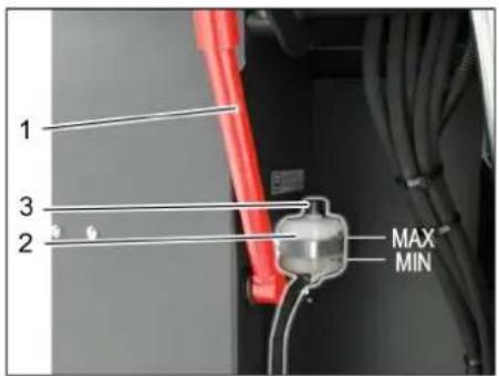
1 Tpmaay 3anobixkhoi utAHn
2 Pe3epByap raIbMiBHOi piINH
3 3anipha kpiuka
→Пднгп pe3epbyap ДЯ CMITTA 3a-ФICyBATN 3a DONOMORO 3anobixhoi wTaHn,ДИВ.ГNaby,CnopoKHeHHpe3epByapy DnA 360py CMITT"
Ipebipntu y doCTaTHbO ralbMIBHOi piHn y BiIOBIDHomy pe3epByapi. Bka3IBka
PBeHb piDnH NOBHeH 3hAxOaHTncMIX No3HaKamN MIN (MiH.) n MAX (MaKc.).
→ Pn Hno6xIDHOCTI DOnHTN DOT-raJIb-MIBHy pIDHny, yO icHy e npoJaxi.
Ipebeipka pibH i doJIbAHn MaCTnla HE6E3NEKA
Hebe3neka oniky!
Damu dbueyHy oxoNohymu.
→ Ipebeipky pIBH MaCTnA y DbIryHi 3diChHOBATN OOHaMHeMeYepe35 XBNINH NICRA BUMNKAHNA DBIryHa.
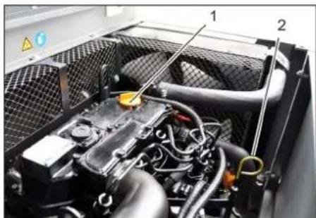
1 MacTINHOJINBbA KpnIka (DvNHyN)
2 Pokachuk pibn MaCTnla
→ BntTHyTn NOKaXnK pIBH MaTnJa.
→ Bnteptn nokxuk i 3HOBy noro BCTaBNTN.
→ Bntarhytn nokakquk pibn MaTuna.
3HrtnnokaaHHpBbMaTna.
3HOBy BCTaBnTn NOKKqNk PiBHa Ma-CTnla.
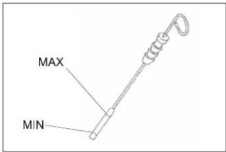
-PiBeHb MaCTnIa NOBHeH nepe6yBaTm MIX BiIMtKamN MIN" i MAX".
-ⅡKIO pIBeHb MaCTnla HIXKYe BiIMtKn "MIN",doJNTn MaCTnIO
- He 3aJIbBaTn MaCTIno BnIe BiIMiTkn "MAX".
BiDrBnHTnTnMaCTNoHAnHBHyKpnuKy.
3aHTMOTOpHeMaTNo. BnrrJaMactnBkazHnBraBi "TexHiHdaii"
3aKpTnMaCTnIOHaINBHy KpnUKy.
3aueknt npHaMIM5XBnH.
→ IpeBipuPiBeHb MaTnJa y DnRhyi.
3amHnB DnHyI MaTnIO Ta fInbTp. OSEPEXHO
Hebe3neka onikie zaprum Momophum MaCnOM!
Dama duayhy oxonohymu.
→Πιρογυβανε ΜΜΗΙCΤβ ΑΝΑ 3ΟΥB MyiHIMyM 6 Μιπριβ MaCTηλ.
→ DAtn DBruryHy OXOIOHyTN.

BnBTHTn npo6ky MaCTNoHANBHO- ro OTbopy.
→ BiBnHTnMaCTNoHAnBHy KpNkY.
3JNTMACHTNO.
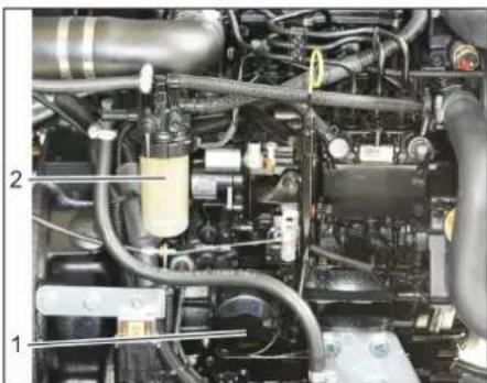
1ΦijbtpДЯ MToPpHOro MaCTnla
2 PanBnHm fInbTp
→ BURBHTTN MACTNJIbHNI φINbTp.
→ PpoHCTnTn KpInnHeHH Ta yuJIbHIOBAJIbHI NOBepxHi.
→ ΠepeBCTaHOBJEHHrM 3MaCTnTm MaCTNJOM yuINbHEHr HOBOrMaCTNJb-HoroΦinbTpY.
BCTAHOBHTHOBMMACTNJBHNIΦINbTp Ta MiHCHO 3aTJTN.
3akpyntnpo6ky-3arnyukydny 3nBy MaCTnla pa30m 3 HOBIM yuiIbHeHrM.
Moment 3atarybaHHa:25Nm
3aHTMOTOPHeMaCTnIO. MapKmactTnTa pBeHb 3anOBHeHHa 3aHaehiB rnaBi "TexHiHaH"
3aKpTmMaCTnIOnHaINBHy KpnUKy.
→ДатиNonpaцюВатиДвигуHy npu6n3-Ho 10 cekyHd.
→ IpebeipuPiBHeMaTnua y DnBnyHi.
Ipebipntn naibBnHn pijtp.
→ Ipeebipntn nannBHH pInbTp Ha ha-RAHbCTb 3a6pydHeHb.
→ Pn Heo6xIDHOCTO uOCTHTN naINBHN pIbTp i Kopnyc pInbTpA 3a Heo6xIDHOCTi 3amHNTn naINBHN pInbTp.
3aHa nHbHoro fIbtpy
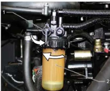
1 PanBnKpaH
2 PanuBnHm qilbTp
3akpnTn npBHH KpaH.
BidrBHTnTa 3amHHTn naHBn
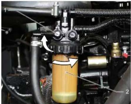
1 PanBnKpaH
2 PanBnHn fJbTp
TNOBIDOMJIEHH
IpeoecmaHOeHnHm3aIObHUMn naJueHuqinbpdu3eHbHMnaJueom.
→ PnKpyTHTN HOBn naNBHn φiNbTp.
3aBHTnTn naINBHH pIbTp 3 kpyTNbHM MOMEHOM 20 Hm.
BIDKpTNnAINBHN KpaH.
3NIB KOHDeHCaty 3 BOOBIdINbHNky Dn3eJbHoro nJIbBa
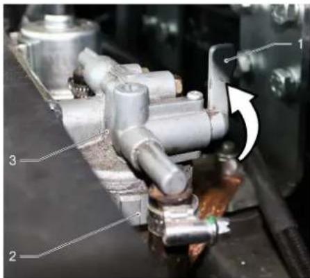
1 PanBnKpaH
2UaBaBidJbHnka
3 KOHDeHcaJIHH TOpIuK
3akpnTn naHHN KpaH.
Bikpyntu auy biinbHnka i cno-poXHTN.
→PnurBnHTnTuayBiDinbHnka.
BIDKpTNnAINBHN KpaH.
Ipebeipnti piBHeB ridaPbNIOHoro
MaCTnJa Ta DoJInr NOrO
NOBIDOMJIEHH
Pe3epeyap 36bopy cmimn He mac 6ymu nihmua.
BikpnKoKxyDnryHa.
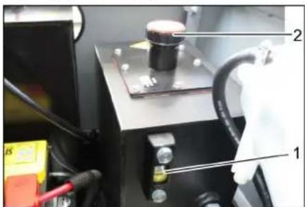
1 OINBOMIPHE cKIO dIg rIpaBNIuHOro MACTnla
2 Kpnka, oTbip nIaIINK MaCTnla
→ Ipebipu npiBHe MaTnA B ripabNiiHn CNTeMI B ORJIOBOMY BIKHI.
-PiBHeb MaCTnIa NOBHeH Inepe6yBaTm MIX BIDMIKAMN "MIN" i "MAX".
-ⅡKIO pIBeHb MaCTnJIa HIXKYe BiIMtKN "MIN",doJNTnMaCTnIO.
→ BiKpyTnTn KpnuKy OTBOPy dna 3aNB-KM MaCTnJa.
OuHCTnO6NaTb3aNBKN.
DOnITn rIpaBNIyHe MaCTNIO. BrrrJaMactNla Bka3aHm B rnaBi "TexHiJi DaHI".
→ HarBnHTnTn KpnuKy OTbOpy dIra 3aJNBKN MaCTHJa.
IpeBiptn ripabniHy yctahOBky IOBIOMJEHH
Texhihe 0cbnyooyeaHn yidpaBniHoi ycmaHOeku Ma3diuchouamu nuwe cepi-cha cnkyka.
3aφikcynte cTOrHouHy rAJIbMiBHy cnCTemy.
3anyCTnDnHyH.
→ IpepeBipu ripabniHhi JhaHn Ta 3cHaHH Ha repMeTnHiCTb.
Ipebipka pibn oxonodkyBaNbHOi piHn
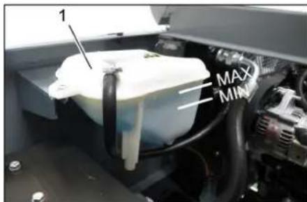
1 KomnHcauiHm 6aohK paiaTopa piHHHOrO OXoJIOxKeHH
PibeHb oxoOnOxyBaNboi piINHnpepeBiprtn nIwe 3a xonoHoro DBruryHa.
→ IpebipntpiBHe3aONBHeHHKOMnHcauiHoro 6aKa paiaatopa piHHoro oxoJOnKeHH. PBeHb oxoJOnJxByaBbHOi piINn NOHN He 3hAxOHTncr MiaN03HaaykamMIN (Min.) n MAX (MaKc.).
Ipebipnt Ta oynctn npiaTop BOIN/riPabNCHORo MaCTnla
HEB3NEKA
Hebe3neKa oniky o6 zapny noeepxHIO i Hebe3neKa onikie npoio!
Bodru padiamop noeuneh ocmyu-mucr Minimym 20 xeuun.
Pibehb oxonodjybanbHOI BOH BpaiaTopa BOIN nepeBipraTcRa HAKOMnEHCauHOMy 6aay CnCTeMn OXoJNOJKeHH.
INB. rnaBy "IpeBipka pIBHr oxonodjkyBaJIbHOI BOH".
OuHCTnI pIaCTnH paIaTopa. YcyHyTN 3a6pydHeHH 3a DOnOMoIO M'koI uITKn, CTNCIoro NOBITpA a6o HeBENIKORTO TCKY BOHN.
→IpeebipuTu wnaHru paiaTopa Ta 3'eHaHHHa uinbHicb.
OuHCTHTNBEHTNJTJTOP.
Ipebeipntn Ban, 0o nidaTae
3aynctntn DBNyH.
→Пингпpe3epByapДЯЗ6opycmITBA NOHTKOBE NOJIOXeHH.
BIMMKHyTN DnBuYH.
3aφikcynte cTOrHOHy rAnbMIBHy cnCTEMY.
BCTAHOBHTN 3aNO6iXHII WTAHNn DnA cnopoxHeHHn iINHrTOIpeepByapy.
→ BuaNTn 3 BaNa, 10 NiMItaC, CTpiKuN MOTy3KN, 10 HAOTaJIcR.
BnHrTn 3anO6jXhi TtAHn.
3aynctnTn DBNyH.
Bidiynyctntn pe3epByap dna 360py cmiT Ta B NOaTKOBe NNOXeHH.
BIMKHTN DBNHyH.
3amihabana,0o niimitac
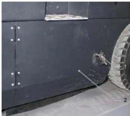
1Kniou
2 BoKobi naheJI
→Пинги Habepx pe3epByap nIg 36opy CMITTA Ta NiDneptn 3a Donomoro 3a-nobikhoJ uTaHn.
Bikpn 6iHy nHaHb 3a Donomoroh KIOUa.
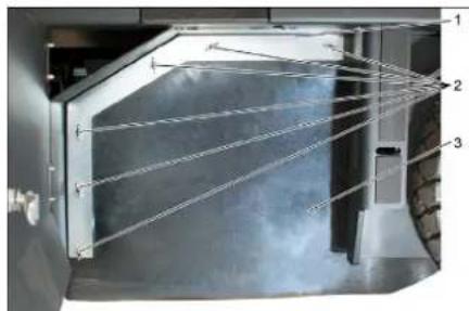
1Плдтуючсokобу
2 CmyuKoBa rauKa
3 Biyuye yujiIbHeHHa
BjrdbHTnTcMyuKoRaikn.
3HIMiTbPiDTPMMyOHyCKo6y.
BidBnHTn CmyKoBi raKn, po3Ta- WOBaHi Ha nlocki CTOnOpHi wa6i, BID 6iHoro yuiJIbHeHH Ta 3Hrtn nnocKy CTOnOpHy wai6y.
BidKHyTu Ha30BHi 6iYe yuiinbHeHHa.
→ BnBHTNTn KpInnBnHn TBnHT TpMaHa Bany, nio niDmita, Ta oBepHytn Ha30BHi npnMaBnHn pncTpI.
BntyHnyBaJ, 0n nIdmitae.
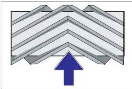
Po3TaUyBaHnB Bana, 10 NiDmitaep npu yctahOBuI no HApymky pyxu (Bnrrnd 3Bepxy)
Bka3iBa: Pnp yctaHOBuHOBO Rana, no niIMiTae, 3BepHyTuYbary Ha noJIOKeHHa TeHH
YCTAHOBHTHOBNBAJI,IOIiIMITAE. Na3n Bany,IOIiIMiTae,NOBHHI 36irTNC3BNUCTyNam6banaHCupa.
Bka3iBaK: NcIy yCTaHOBKn HOBO rNIMiTaNbHOro Bany Heo6xIDHO 3aHOBO BipeRyIOBAtn PNOuHny NiMItAHHa.
Ipebeipka KopektyBaHH nlounnn niIMiTAHn DnB aJa, 0o NiIMiTae
BIMKHYTN BCMOKTyBaJIbHn BEHTNJTOp.
→ NocTaNMaHHy, uO NiIMiTae, HApBHy rIaKny iNOry, NOKpTu BUNMM WapOM NITy aO MeJa.
Onyctn3a donomoroBaxkeIO nIKepyBaHHBaJ, 10 niIMtae i dAtn npnaDy nonpaQOBATn (np6I. 10 c).
PiHnBn, nO niMiTaE.
→ DAtn npncptpo 3aHi xi.
→ Ipepebipntn nloosHy niDMiTahHna.

PpOJIb NiIMiTAHH NOBHeH MaTn BnTnI pIBHomipHO npMOKyTHnKa uNpHNO 80-85 MM.
MOHTyBaHH npophiIO nIdmitaHH
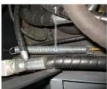
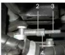
1Пужина
2 PernylIOBaJIbHa raIka
3KoHTpraKa
4PizbboBmUToK
BidperyIOBaTHNnonoKeHHnnpoepiHIO nIMiTAHNNIINXOMnepeCTaHOBKn peRyIOBAHBOHO TBHHTA.
→ IpeBipu nnnoHny niMiTaHHa.
IpeBipka Ta KopeKryBaHn npoPijIO nIDmitaHH dA Bana, 0n iDmitae
→PiHaTn 6iHi uItkn.
→ NocTABUN MaunHy, 10 NiIMiTae, HApBHy rnaKy niDnory, nOKpTu BnINMM Wapom nny a6o mea.
Onycttn6iHy iItky iDatni nonpa- tOBaTN np6n.10 cekyHd.
→PiHaHTn 6iHi uTKn.
→ DAtn npncptpo 3aDHi xiD.
→ IpeBipuTn nIoUHny niDMiTahHH.

HINHA npophiNIO nIDMITAHNHOBHHCA tAHOBHTN BiD 40 Do 50 MM.
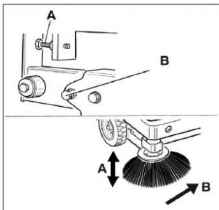
→ BiDperyIIOBAtn noLoXeHn nnocKcTi nIMtaHHa 3a DOnomOrHO DBOx perYIOBaIbHX TBnHTIB.
→IpebipuTnPiouunHy NiMiTaHHa.
BctahOBHTn 6iHi yuihHeHHr
HEBE3NEKA
Hebe3neka mpaemyeaHnHa!
3aexdu npu niohymomy peepeyapi 07360py cmimmae moeobamu 3ano6ixhi umhaue.
Bukohyeamu 3axum minbku 3306Hi He6e3neuHOJ 3OHU.
→ΠiHЯтн Habepx pe3epeByap nIЯ 360py CMITRA Ta 3aФICKYBAtn 3a DOnOMORO O 3ano6ixHOUtaHn.
→ BiKHyTu HABepx 3an06ixHy wTaHry DnA CnpOpxHHN iDnHrTO pe3epBy- apy i BCTaBtTu ii y TpMaay (3an06ixHn)

1 Tpmaay 3anobixkhoi wtaHn
23anobixha uTaHra
→ BiikpnTn 6iHy naHEnb, kONuCaHO B rIaBi "3AmHa BAly, uO niDMiTae" Bu- ue.
Ocnabnt6cmykoBnxraokHa6iHn nlockcnctonophiu6i.
Ocna6ntn3raaKn(SW13)Ha nepeDHi nnocki ctonopHni wa6i.
→ HatnckyBaTn 6iHHe yuINbHenHbHN3 (noDOBXHi OTBip),NOKn Noro KpaH He BnABtbcHa BiCTaHI 1-3 MM BiD NiID-NOR.
→ PnRbHHTttn nNoCKy cTOnOpHy wai6y.
→ NOBTOPIN NOCIIDOBHICTbIaIHWOI CTOPOHnPnCTPOU.
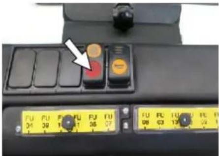
OuichiHnHnΦinbTpynny npnyypyHy
→ YbIMKHyTN pyHne OunuEHHN HcIbTpA: IpeBepHTN/3aMInHTN pINbTp dna nnny △NONEPEDXEHH
Hebe3neka mpaemyeaHnHa!
→ Ppu pobomi 3 φinbmpyéanbHIO ycma-HOBKOIO Hocumu Macky dny 3axucmy bID nuny. Dompumyeamucn npunucnb no mexhiü 6e3neku bIDHOO obiy i3 dpibHum nIOM.
→ BnKoHaTn YIeHnH φiNbTpY dIa nIy 3a DOnOMorO KHOKn YIeHnH φiNbTpY.
→ CnpoxhntpupeepByapI36opy CMITTA.

1 BnokyBaHHKpnuK npncTpoH
2KpnuKa npncTropo
3 Kpnska qinbtra
→ BiKpnTu 6nOkyBaHHa. Dna UboRo He-06xHOb BiKpyTtTu TBnHT 3 roNIBKOHO y BuRnJa 3ipOuKn.
→ BiKHyTn KpnuKy npncTropo Bnepei.
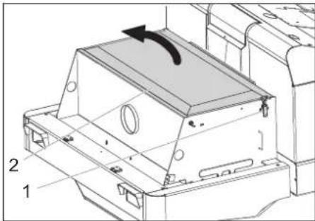
1 3amok, kpnuka fiNbtpa (2x)
2KpnuKaΦinbTpa
BjdkpnTn 3AMOK.
Bikpnkpiu kipu kipnbpa.
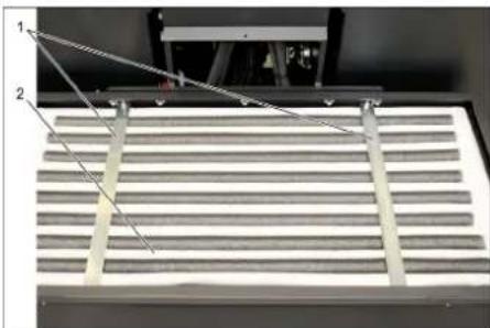
1PonepeHi nlaHKn
2Пиловифытр
→ ΠepeBipuTn φiNbTp dna nny, npu He-06xHocTi Ouchntu N 3amHHTN.
Bka3iBka
3amHy pInbTpA dnn nny Do3BOnrReTbc npoBoaHTn TInbKn cnIBpObiTHnKaM cepBicHOi cnyK6n fipMn Karcher.
BcTaHOBIb Ta 3aΦiKcyTe KpUkky φinbtpa.
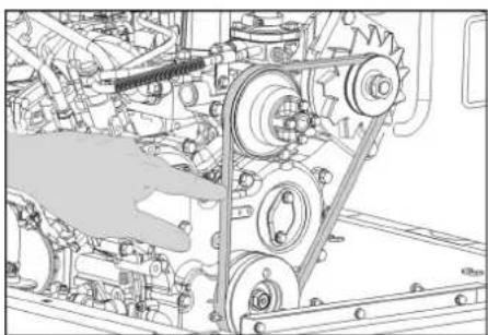
Ipebeipnt Ta BiDperyIHOBaTn KINHOBpuMihb
KJIINHOBNIpeMHb npn TNCy 10 KI NOBUNHeH npOBncATN 6NI3bKO Ha 7-9 MM.
→ HataHHHKNHOBOPOpeMeHA BCTAHOBIOEbCnYNOBHOBAKeHM npauiHBNKOM cepBicHO CIyKoN.
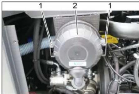
Ipebeipka 3amHa nobitpHoro
fInbtpa
13aTnckau
2 Kopnyc nobitprnofoinbtpa
3HrTu 6iHy naHenb.
3HrTu Kopnyc noBirpHoro fInbtpy.
3amHHTn nATPOH NOBITpHoro fInbTpy.
Bka3iBa: MoHTaxHne NOIOXeHHa -BEHTNJIcIHn OTBip HapabJeHH BHN3 (INB.MaJIOHOK).
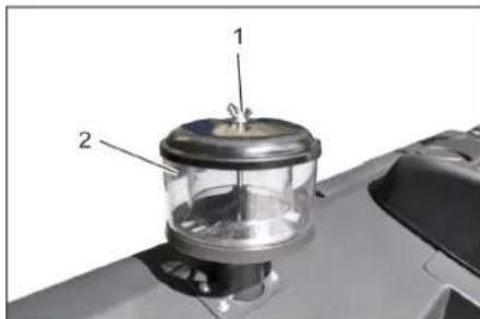
OuHCTHTN BiDuceHTPOBn cenapaTop
1 Cmyukoba raika
2 Biüntpobn cenapatop
BidiBnHTn CMyKOBy raKy Ha BiD-ueHTPOBOMcnapaTopoBI.
OuHCTnB BIDueHTpOBn cenapatop.
3amihntn 3an06ixhkn
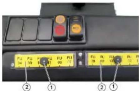
1TaNka3HacikkoIO
2 Kpnka 6IOKy 3anobixhnikiB
→ BnKpyTtN rAky 3 NOOBXHbOHO HAKaT-KOIO.
BikpnKpNkUHa 6nOci 3anO6iHNKIB.
→IpebeipTu3anO6iHKn.
Hecnpabhi 3anobixHHNK 3amHHTN. BkaibKa: BnKOpNCTOBByBaTn 3anobixHHKN JIiue 3 OHaKOBUM 3HaueHHM.
Bka3iBka: 3anobixnK FU 01 3haxoJtbcra B nikanoTHOMy npoctoPI.
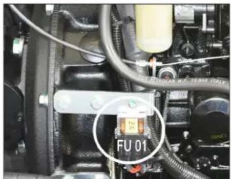
Chairman of the Board of Management

S. Reiser
Director Regulatory Affairs & Certification
YnOBHOBaXeHHn CnIBpO6iTHNK NO BeDeHHIO DOKyMeHTo06iRy:
S. Reiser
Alfred Kärcher SE & Co. KG
71364 Winnenden (Germany)
Tel.: +49 7195 14-0
Fax: +49 7195 14-2212
Winnenden, 2020/01/01
www.kaercher.com/REACH
质量保证
aous Jus Jus Jus Jus Jus
Karcher eLac
aLg jlll csc
logall wll baojao
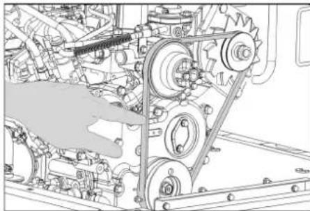
laia,paieZ,logaJl
a ≥ 5100j12
aagaaal a a>lae
.0ai 0e 1oc a025 jy0sJ
0ggl
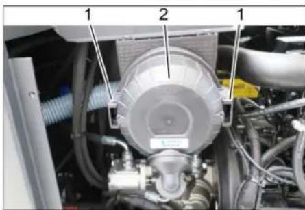
01
olgal 2
auiuiooosJgij
glgl 2d3 a. c
clggljwlaawgbjx
a29 ogS i 100 wS jll gog kabbzdo
y aill. (o)
sallal oag Jolal Jolal cbb
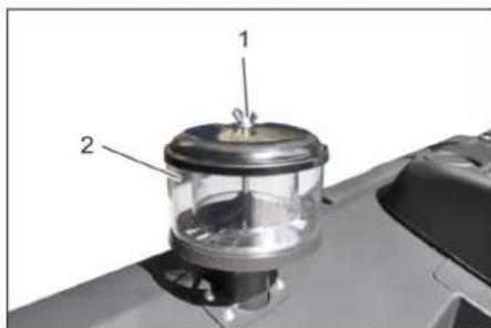
aixialgolal 1
sJall jll oJol Jol 2
0g>gol all algoal alp
sJrallalol oag Jolal Jolall
JallogjJolll Jolll aai
.
gaaa a
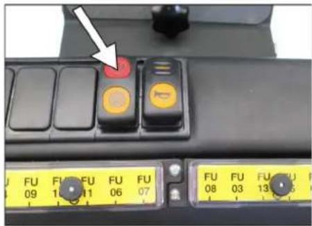
Jssu ssu uusu
a) 100
x1 = -b - ^2 - 4ac2a,x2 = -b + ^2 - 4ac2a
y1, bx=la lo
Jlac/1jx/ xic Jell/oo a Lg// fLg ij
b_2 = 1
<aaolai
<20g
yss
090).(
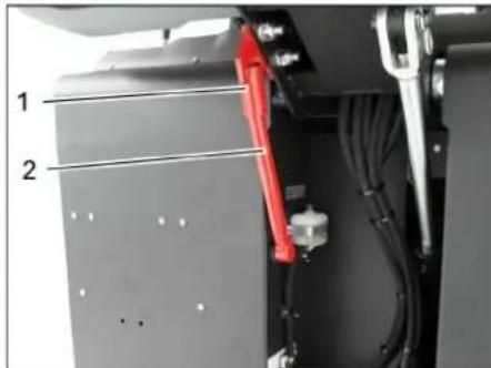
100 100
2
Jg 929wogoslos auiologss
"0jglJ 1
g>galll a>all Jolgal Jp
y
g>gall (SW 13jolgal j
wllpksiaicbciaill
aai aai jll (ajgall axial) Jaa
3-1gJgJy
cui|la|b2pss
jglj jilwla 1a
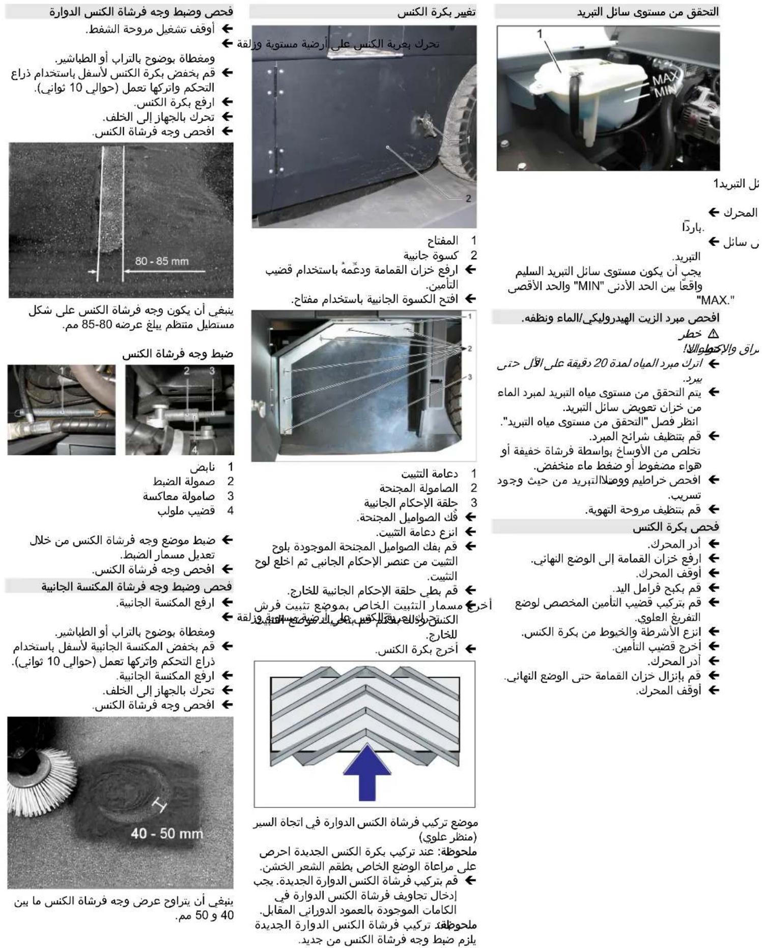
jla clal Jolai csiall clal aai p 1ggl
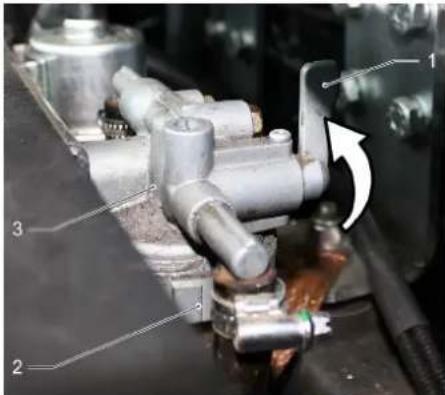
ggl 1
2
clll 3
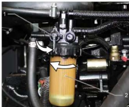
ggl 1 ggl 2
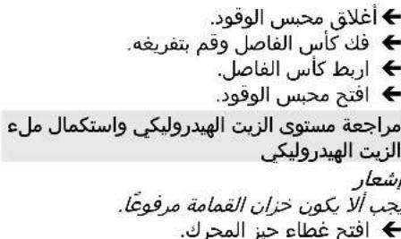
2Jolal
ggl 20 gcl <0ggl
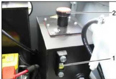
Sgljllwjjaa 1 wjjcJg2
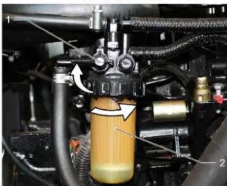
ggl 1 ggl 2
aill adlc cuiy ci jil yaiMol
XI, MAX.
<.wJl
∈Jol.J
alolgall jjbjcjj aegn aed
.0jll
E
j011wjjgmo a>J
Jjll jjIg jjll
4
1.5lu/2al/2j 1.5u/2j
6 120 aagaaal aggaaaag a< jll Lc JrJrJrJrJrJr
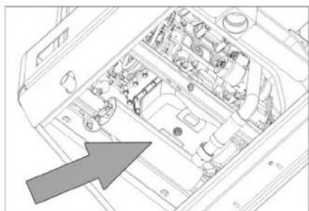
cui jai 1
←.wJL
Cjll Cuiu
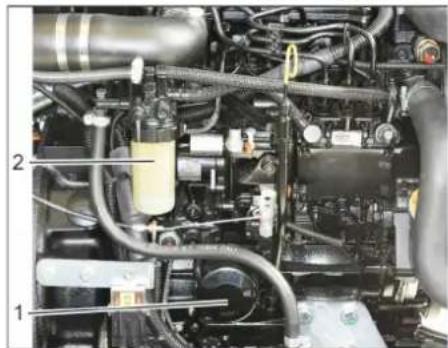
Jzall Cj 1
2gglj 2
. 1
Cjlll Cjll j0s> aic 0
1g 2jll j
25:
<Jol.
J29 j21 cJall aasg cuJll aegj 89al
cujll
10 10 10 10
←
gaggl
L 1000000000000000000000000000000000000000000000000000000
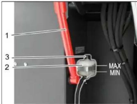
1000000000000000000000000000
JolaljIwag2
3
aolal aolal 1 j 10
[1]J 10 10 10
"olaal
jIw aIg> 1gio 151 lo gao
Jolal Jilw no a95 aos Joljell abgdo
J 1
Joljll jilw 100d.0gall all> .U> UJr jgdiDOT
jill Jo JalSsiug jzall cuj sGsinu a>Jro
S = S
- 1 ≤ ( a + b) ( a + b) y ≤ 1 , b > 0
2a//j
Jzall Cj sGaiol a>Ja ulac cJg JJIe gJd jax Jzall

a aae 1000000000000000000000000000000000000000000000000000
JooJooJooJooJooJooJooJoo
j>wwjg>JaaJbll>wpi
aJlll j0yg| aRgSll asll no
LjzJyJyJyJyJyJyJy
JU 112aJI aJI 10a9)
aJbUd
(-)JlllIaill Jgjbdlae
.(+)gall sbal Jgj bJ 0
aJbll oedc golgo
aJbllcogoo aJbllglsl
glll aab asglwal aJbll no abti
.
Jilw eJo oJol jol all Jilw sGss a>Jol
1 = 2
y1,y2
cogloicolil cui29pulwla lalps
y1( 1,2) = 1,y2( 2)
sll2,02gjall llllal 109puiu
a/la9 aI> 9 baiell cia Juiw Jaiell
2ab ≥ 4
y1( x) = y1( 1 - x^2)
y aLw
y1,12≥a|l,1g≤a|2.
4a
y1y2 = y1y0
x_0 < x ≤ 100
11
y1.j2y
gucu/ uagj/ jui/ jz 10021 / ggi// o w j dlu cai
Lai, aIblll 2w lq pui jlc
uulc u19 s. uull aula
k_2 =
y1( x2 + 1) = y1( x2)
0g9aaS;0u//g u//c/1
jaa//1/la9 jll all
.0w//j/ jie//Jc
gall lcl aalll oj jlc 1d1e
Jauu
gugogag aIbail
auiu jglzuy auiiuy uulg jge
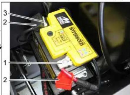
gall 1
ab 2
JwJb3
aJbllcogooaJbll
cillgolgo 1yllb> y
aJbUdd
aill(a>JLJI)Jgjb Jogg
( +) > 0 1
.(-) JL
aalaae
N>0a1sla>g>g0ssllg
aJlll lal 11111111
a
go b@) aagj yll Jilw gssaa>J
aaialln mnnn nnnn nn nnnn
(1)
a
m = 311 或 m = - 4
a22/ll ooglaal /yllla//
aioo ojag jIuIgGuo a>J
JgjIg jyI yIyI Jgge
wuao piauuiy a15 joo auc uauo 9
ai + 1ai = 1
a2jg bao aigaa jlll lloic
1.28jaa>Jggljgglg0°20JrJ>JI
10>5
a> a>aa>aa>aa>aa>aa>aa>aa>aa>aa>aa>aa>aa>aa>aa>aa>aa>aa>aa>aa>aa>aa>aa>aa>aa>aa>aa>aa>aa>aa>aa>aa>aa>aa>aa>aa>aa>aa>aa>aa>aa>aa>aa>aa>aa>aa>aa>aa>aa>aa>aa>aaa
1.28g1nJaaJooJooJoo
即 p_2 > 5
a a aLw
如:
a_i a j
gss lssuill u29 p/uuiw, la3p
lo9o aoiaolj
aia 2y y/10w//p> y
k > 2

1
2
gogj aasall jolll 9
Jalal jal alg jgl g jglg jglg jgl
(oo)
Jz all 1g E 2dall 20
Jz jll g Jdall g aifll w g
aill cgl pge y. aill
y aai jll 2dall w jll no all
. ai jll

aJyIaIyI aJyI aJyI aJyI
Jolal 1i ailll l 10
:JbJg
1dLwylolcJc J 00rjg jlll 1000

a/90j/la/cj/1,
.
Jb

y1( x1,y1) ,y2( x2,y2)

gogj jw gjjL Wai j2x

10/12


lJy/1JzLw/

a1 + a2 + a_3 = 6

15

g210 9 a/la// clal y

jll aai 9 aai 9 pssw
"0" 0000000000000000000000000000000000000000
.8aall Jg no a2w|g
←.Jl
J 10
oJgulss 2c p1s w
aJlll aIbIyI bIaIolcI rJ
Jjwj
aagg aogg ggggall
0slo, 0a 05 aos ,0g, 0s8g wll
aai
jIgJ1J1J1J0JusJiae aai
.
0g 2e 1
y
aIulalgl aIizll
aolc|dawj
4
- all 2. all
jLJU2yE
a_0 > 0, = 1
aaxo a 109 10g/82
← gjmaill jggsjbs) biaill lcl
(1)
<.Jolj 25
kx
a1 = 23,b2 = - 43,b_3 = - 13
a/90jIb1gJl/100gE/1/
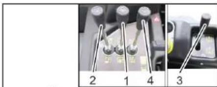
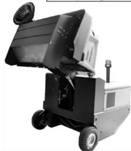
pLxwLy aJyIaIyIaIyIg yIyIyIyIyIyIyIyIyIyIyIyIyIyIyIyIyIyIyIyIyIyIyIyIyIyIyIyIyIyIyIyIyIyIyIyIyIyIyIyIyIyIyIyIyIyIyIy
gJgSsU 1uJgUeU (4)
gj jg jolg aalall jgs
alll jxall lal sbc bao alwog wol
1g bai>lg Jolal aWg 1c baoi .abgs
Jol9
0"gogll jjol oJzao 1
jlll eae sccg
c:poU(4)ulssllae pseglj
aolaluljusuuljlll
glu:alU (4) uljull elacpse jgj .aolall jss uuljull elac
aJbJI aJbJI
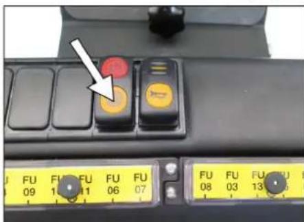
a0gjz
:ablll 1
jssw:poUJ(1)wsUoSsE
Jawyogajgllwslal
cai:pouU(4)uljolllalacpsgj 1
aJgJgJgJgJgJg
:loU (3) aWbI aWscal pSsEj
Jawy jaoa aai all
aiillgaiabll aiojll
a>gjll 1
:
Jz:poU (1) jssj oR sEg JwOgJU
a:paU (4)uljall elae pssg j
aJgJgJgJgJgJgJg
:olU (3) aIulI aIusall sEgj
Jawy jaxw axlal axisall
aolaliljg
2ds
y1( k > 0)
olw/sdsgaaaygulaccl
. aolal/1j> j> aebio g 1
sul,9 aguuauo uo/1 dc jg21 lglu p
.
2
a + b = 2
aill aolll jiaai laiag y Jy aiY 8gjogjll Jawl cei y. gail
4u
- | x,y| = 10 .
o oalio 100 100 100 100 100 100 100 100 100 100 100 100 100 100
a95 a9luai, 1u, sla/
Jll
42
y1, jas^1jal_0
ydl//gj ydl/1c 0g
1j aui//aig jfo sb s /dc ogb> s/
yj,
oalilas
<9
Lw wll acw.aW
←yεJw
sulg jall pailll lla 1
<11J20
.aaJgOe 00000000000000000000000000000000000000
al
aloo ggl aolg cdoa oao 1i jia
.
JcIb2aill Jolal aIe joo Saa:abgdo
Jolalaw
gillglj
70 Jgglb jy jyjg jy
gglalbljlaI xicovrJgcbu, pjjl
:70 1gbsy jil yll gilgjIz
aio piaowy jgjgljgjy
auiio 2gso
#
4
log17Lw/1g aaow/1abpaw/1wosy
uuiI LsLs o joo 003 uuuu 189,4w
m : x = 1 或 3x + 4y + 1 = 0
yai yai 10000000000000000000000000000000000000000000000000000
aJil9 aai jiai uli:abgdo .aaoo aoj o
aill jell aebio jjll Jss i: sJ 50
a=11
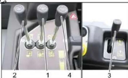
1
aolaluljdsps2g1j 2
aaiJJI aaiSall pS> 3
1j jlllbae aSx 4
aui oS, pS> EJ3
jao:poU(1)uSUIoSxE
Jawjgdlwssllol
gj:cll (1) jssj sscj
JeJgJUwSILdW
aolall jj sss
jao:oluU (2) aooll ulj sOx elj
Jawy aolaoall jss
gjy:al2l (2) aolall 1j> s<glj <y aolall j
aull aaiSoll aS> 1j
:poU (3) aJJI aSall s
Jawj Jaaa aJll aaSall
1 1
"oJU" 2
"alil" 3
pUJall lal ssc bao alwog J. (Jjall lal ssc) loai
abgsioa
Jol Jolg jolp 0
Poi Jl Oda
c.bw"poL"EjawllawgJc baoi
ailllll Jace
J 1
ggljgJo gssg>
j>all wj sgimoo a>1rρ
jIw jgszuljscJall sGswu
.
aaiI aasalg wssll oJ a> a< aiao abjai g> gJ 5Jg> g a9galo abjai g> g> jzai
sJall jolll Jolll Jolll 1
.0gjll ic lagabu, gglg jilg
oic akl glbgl llaa 1
JLAsWJ
jgljlllglggeo 000
aai 150 150
1 = 2
1,12,12,11,12,12
yolaijio ygsia//gog/
Jueui/
aiaea/1sloV1 28g/2g
gagco gjg jg jg j111
a2w/1//2g9//JgogpocLc0
. a > l_ 11
a a
.8g9g11 a
JJJJIgI
.0g0|1j>0s1swz
.1JzJl 0sJw
#
jll 1
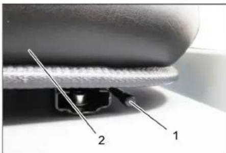
2021高考真题解析
jlll 2
111111111111111
a g jj j j j a a
ploW asN> no aal 5
<1g.baiolgJoljellawlglaBaiol
Juswll Jss
gagol jolr
Jolalawgs Jc baoi
←y
y1
Jc slaicll 0g gglw wss aegd j

1V aIwll
jLd
<.
←
gglglggl
yacagalgbolua/ jll/gjllc
例 10. 如图
gao jj ojjgljll ojjol jcljll
.
yLgJl,us a,e,dy,de
( 0, 4) ± 1 ②
1
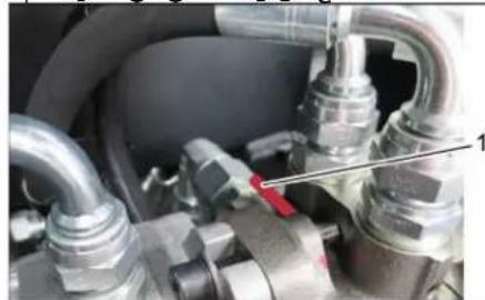
20g-JawWaiWll alxg 1
0jllg jll 0jll jll l jll 0jll lglg jll g jll aall 0jll g jll g jll g jll g jll
#
aolc
J 1 J 1 1 1 1 1 1 1 1 1 1 1 1 1 1 1 1 1 1 1 1 1 1 1 1 1 1 1 1 1
←
aagua aiojIe uuSJI aue 1
<.
Jolj0s
aLg/1j9y4i/y.425u//oJSLI 3y
jglll jai aolll aoaowll o
aIg aIglll aolll aolll
Jglia//wgljg//jai
g/aclj>glu g/auuogjge//a,b
.5.1/4.6.69//
Jlac/sj>1uc a/la//
.
jglpobj,polaiwlpjzllcui jg
91,aailljg32022)laiaI/llc slo
(1)①②③④
a1 = 2,a2 = - 4, b_2^2 = 4a
uuuuaio uuii juo g o g i
a15, aewg ayjuy gria Jzai/1i
a11111111111111
y/lu//2g/8u@g/0s/1/2g/0c/1
aalall alalai jgjglwll aes
Jai Jc oJgJU wSJI oJoo
a a a a a a a a a a a a a a a a a a a a
.
jzJJJJzJdzJz
j_S =
1.2xUg4LdU 2.2xU
1jz//sic jgl//jjg ocl/
1Sgawglo sIoo
jgl/111111111111
*a8920 (wlll 100)
[1]
.
wiojxio|xiw|jglxllxw
laolgl
Llooljo yjdoipwuiic
70 00yll yolulgla
lagjla//Jaaiw/ jia//Lc
ool 104xlc yas lo5.oo2o/1010a
90,211,2g;0g;0g 8a,b/2a//
abw/gjg≥1/0.12iWjJas/ol>ai
Jlaby aobg, JI p
1g/1g lalsteill oclj ydawl/ adog
LJAL/1Lc aJluw//gJyUg
g> 1/25jJ Jae//cJ
Jaoi g 150 o a cgo go a la21 /
J
//g2//g9gC//jina//j@//jia
15Xiaall 9/2011 jxw/1go
ylo o/olc/o fua/ y
wll JaeI e i d eiv jaiia
//i2g.a
()w/1Jzal/Jz9/Jz/
a/10 1010
1a0c//
1/laIb a910 993 1g21 /j, j, j, j, j, j
oo 0joo 0jioaWJg2y, Jioo Jzll
Jolol J2al/09g 1y j
ωg ωgaaa/1 μc 152/120 j42/1
J201/ooj/s
jolw/ j0o j111 /p111
0121212 0000000000
J>aII
pIwJyjgJy
gwl/olw/g102w/
aegs; gjg/1jg>11p012wU, 9 aqj1.29
a012xwl, a>1,0
0j0j0j0j0j0j0j0j0
a/00gile 11111111
guy gj aXg j aau> g aui Lolc
jWy1p11j1y1a9eao//g/9o
gipduu wiaa/ aiai / 10 p
aill iio o lae ie 10g> 10
jz//1i0/12w/4a5
puc pco 5u/laab/ afo
j( q) ≥ 14
aJdla aL
A//1 - n 为 AQ//A
a1 = 23,a2 = - 43,b1 = 56,b2 = - 38
.0sul//gjla//oJla//acwpi:
jaw, mss, jla211 plaaewu 12
Jlssu aI Jg jgljg o jll
gio9.1yaiol gl aiaiaiaa ylaalgl
gl jll llae ggl jll Jll Jw
jai jia jia aabio 2gill
jzjzjjzjjzjj
c0001 2g
aJai gJgJ a>Jj 2gawu
jIJI1iO pU2sawuL
J
auiuaiy
a>Jd
wJ
aJl
aLwlll
pIaWyI aosw 1sIw]
aioiua//jjgl//gojgl//229
aio 10o o d jg pio
aI>11SjA13jFauuI aSuaq aI>1
j01,0x2xw/ 1xLc 4aLw
jio)0jbs jblio jglj11p1suiw/sic
a0sU//1c/gaypuiy/2(gog//
jgljjwliqjz.
12x + 5 = 1
A//1 - n 为 AQ//S
14/12,11/10
jla>aaW jg2//pddiiu
j//jblia//j//jg,la/lu//j
abolw/ jcyl JeJ JuaI
| الله صَبْرِّة الحَلَّهُ لَالعَلَّة الحَلَّة الحَلَّة الحَلَّة الحَلَّة الحَلَّة الحَلَّة الحَلَّة الحَلَّة الحَلَّة الحَلَّة الحَلَّة الحَلَّة الحَلَّة الحَلَّة الحَلَّة الحَلَّة الحَلَ�دِي الله صَبْرِّة الحَلَّة الحَلَّة الحَلَّة الحَلَّة الحَلَ"الله صَبْرِّة الحَلَ"الله صَبْرِ"الله صَبْرِ"الله صَبْرِ"الله صَبْرِ"الله صَبْرِ"الله صَبْرِ"الله صَبْرِ"الله صَبْرِ"الله صَبْرِ"الله صَبْرِ"الله صَبْرِ"الله صَبْرِ" الله صَبْرِ"الله صَبْرِ"الله صَبْرِ"الله صَبْرِ"الله صَبْرِ"الله صَبْرِ"الله صَبْرِ"الله صَبْرِ"الله صَبْرِ"الله صَبْرِ"الله صَبْرِ" |
| الله صَبْرِ"الله صَبْرِ"الله صَبْرِ"الله صَبْرِ"الله صَبْرِ"الله صَبْرِ" |
| الله صَبْرِ"الله صَبْرِ"الله صَبْرِ" |
| الله صَبْرِ"الله صَبْرِ" |
| الله صَبْرِ"الله صَبْرِ" |
| الله صَبْرِ" |
| الله صَبْرِ" |
| الله صَبْرِ" |
| الله صَبْرِ" |
| الله صَبْرِ" |
| الله صَبْرِ" |
| الله صَبْرِ" |
| الله صَبْرِ" |
| الله ص⁄طَم⁄طَم⁄طَم⁄طَم⁄طَم⁄طَم⁄طَم⁄طَم⁄طَم⁄طَم⁄طَم⁄طَم⁄طَم⁄طَم⁄طَm⁄طَm⁄طَm⁄طَm⁄طَm⁄طَm⁄طَm⁄طَm⁄طَm⁄طَm⁄طَm⁄طَm⁄طَm⁄ط⁄t⁄t⁄t⁄t⁄t⁄t⁄t⁄t⁄t⁄t⁄t⁄t⁄t⁄t⁄t⁄t⁄t⁄t⁄t⁄t⁄t⁄t⁄t⁄t⁄t⁄t⁄t⁄t⁄t⁄t⁄t⁄t⁄t⁄t⁄t⁄t⁄t⁄t⁄t⁄t⁄t⁄t⁄t⁄t⁄t⁄t⁄t⁄t⁄t⁄t⁄ t⁄t⁄t⁄t⁄t⁄t⁄t⁄t⁄t⁄t⁄t⁄t⁄t⁄t⁄t⁄t⁄t⁄t⁄t⁄t⁄t⁄t⁄t⁄t⁄t⁄t⁄t⁄t⁄t⁄t⁄t⁄t⁄t⁄t⁄t⁄t⁄t⁄t⁄t⁄t⁄t⁄t⁄t⁄t⁄t⁄t⁄t⁄t⁄t⁄t⁄ |
| a#ll a#ll a#ll a#ll a#ll a#ll a#ll a#ll a#ll a#ll a#ll a#ll a#ll a#ll a#ll a#ll a#ll a#ll a#ll a#ll a#ll a#ll a#ll a#ll a#ll a#ll a#ll a#ll a#ll a#ll a#ll a#ll a#ll a#ll a## | |
| a#ll a#ll a#ll a#ll a#ll a#ll a#ll a#ll a#ll a#ll a#ll a#ll a#ll a#ll a#ll a#ll a#ll a#ll a#ll a#ll a#ll a#ll a#ll a#ll a#ll a#ll a#ll a#ll a#ll a#ll a#ll a#ll a#ell a#ll a#ll a#ll a#ll a#ll a#ll a#ll a#ll a#ll a#ll a#ll a#ll a#ll a#ll a#ll a#ll a#ll a#ll a#ll a#ll a#ll a#ll a#ll a#ll a#ll a#ll a#ll a#ll a#ll a#ll a#ll a#ll a#ll | |
| a#ll a#ll a#ll a#ll a#ll a#ll a#ll a#ll a#ll a#ll a#ll a#ll a#ll a#ll a#ll a#ll a#ll a#ll a#ll a#ll a#ll a#ll a#ll a#ll a#ll a#ll a#ll a#ll a#ll a#ll a#ll a#ell a#ll a## | |
| a#ll a#ll a#ll a#ll a#ll a#ll a#ll a#ll a#ll a#ll a#ll a#ll a#ll a#ll a#ll a#ll a#ll a#ll a#ll a#ll a#ll a#ll a#ll a#ll a#ll a#ll a#ll a#ll a#ll a#ll | |
| a#ll a#ll 1/2 a#ll a#ll a#ll a#ll a#ll a#ll a#ll a#ll a#ll a#ll a#ll a#ll a#ll a#ll a#ll a#ll a#ll a#ll a#ll a#ll a#ll a#ll a#ll a#ll a#ll a#ll a#ll a#ll a#ll a#ll a#ll a#ll a#ll 1/2 a#ll a#ll a#ll a#ll a#ll a#ll a#ll a#ll a#ll a#ll a#ll a#ll a#ll a#ll a#ll a#ll a#ll a#ll a#ll a#ll a#ll a#ll a#ll a#ll a#ll a#ll a#ll a#ll a#ll a#ll 1/2 a#ll a#ell a#ll a#ell a#ell a#ell a#ell a#ell a#ell a#ell a#ell a#ell a#ell a#ell a#ell a#ell a#ell a#ell a#ell a#ell a#ell a#ell a#ell a#ell a#ell a#ell a#ell a#ell a#ell a#ell a#ell a#ell a#ell a#ell a#ell a#ell a#ell 1/2 a#ell a#ell a#ell a#ell a#ell a#ell a#ell a#ell a#ell a#ell a#ell a#ell a#ell a#ell a#ell a#ell a#ell a#ell a#ell a#ell a#ell a#ell a#ell a#ell a#ell a#ell a#ell a#ell a#ell a#ell a#ell a#ell a#ell | |
| a#ll a#ll a#ll a#ll a#ll a#ll a#ll a#ll a#ll a#ll a#ll a#ll a#ll a#ll a#ll a#ll a#ll a#ll a#ll a#ll a#ll a#ll a#ll a#ll a#ll a#ll a#ll a#ll a#ll a#ll a#ll a#ill a#ll a#ll a#ll a#ll a#ll a#ll a#ll a#ll a#ll a#ll a#ll a#ll a#ll a#ll a#ll a#ll a#ll a#ll a#ll a#ll a#ll a#ll a#ll a#ll a#ll a#ll a#ll a#ll a#ll a#ll a#ll a#ll a#ll a#ll a#ll a#ll a#ll a#ll a#ll a#ll a#ll a#ll a#ll a#ll a#ll a#ll a#ll a#ll a#ll a#ll a#ll a#ll a#ll a#ll a#ll a#ll a#ll a#ll a#ll a#ll a#ll a#ll a#ll a#ll a#ll a#ll b## | |
| a#ll a#ll a#ll a#ll a#ll a#ll a#ll a#ll a#ll a#ll a#ll a#ll a#ll a#ll a#ll a#ll a#ll a#ll a#ll a#ll a#ll a#ll a#ll a#ll a#ll a#ll a#ll a#ll a#ll a#ll a#ll a## | |
| a## | |
| a## | |
| a## | |
| a## | |
| a## | |
| a## | |
| a## | |
| a## | |
| a## | |
| a## | |
| a## | |
| a## | |
| a## | |
| a## | |
| a## | |
| a## | |
| a## |
| AR | ... | aill ala |
| AR | ... | aill ala |
| AR | ... | aill ala |
| AR | ... | aill ala |
| AR | ... | aill ala |
| AR | ... | aill ala |
| AR | ... | aill ala |
| AR | ... | aill ala |
| AR | ... | aill ala |
| AR | ... | aill ala |
![Kärcher KM 130300 R D Classic - pIaWyI aosw 1sIw] - 1](/content/2026/03/555201/images/dc8d1ab047206b71a6f968a4ef6ea52f3f6f787ba9b67b59548e0f9152b16a81.jpg)
THANK YOU!
MERCI! DANKE! iGRACIAS!
Register your product and benefit from many advantages.
www.kaercher.com/welcome ★★★★★
Rate your product and tell us your opinion.
www.kaercher.com/dealersearch
Alfred Kärcher SE & Co. KG
Alfred-Karcher-Str.28-40
71364 Winnenden (Germany)
Tel.: +49 7195 14-0
Fax: +49 7195 14-2212