RS PRO P1 Flat S - Lamp STEINEL - Free user manual and instructions
Find the device manual for free RS PRO P1 Flat S STEINEL in PDF.

User questions about RS PRO P1 Flat S STEINEL
0 question about this device. Answer the ones you know or ask your own.
Ask a new question about this device
Download the instructions for your Lamp in PDF format for free! Find your manual RS PRO P1 Flat S - STEINEL and take your electronic device back in hand. On this page are published all the documents necessary for the use of your device. RS PRO P1 Flat S by STEINEL.
USER MANUAL RS PRO P1 Flat S STEINEL
GB.....15 Follow written instructions!
RU.....181 Co6nOaTb TeKcToByo HnCTpyKcnIO!
1.1 P1 $/P2 S


1.2 P1 $ FLAT / P2 S FLAT


1.7 P2 $ / P3 S / P2 S FLAT
1.9 EM
1.8 P2 $ EM / P3 S EM / P2 S FLAT EM
1.10
1.1
2.2
2.3

2.4
2.5
2.1
DE
Please read carefully and keep in a safe place.
- Under copyright. Reproduction either in whole or in part only with our consent.
- Subject to change in the interest of technical progress.
Symbols

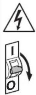
Hazard warning!

Reference to other information in the document.
2. General safety precautions

Disconnect the power supply before attempting any work on the unit.
- During installation, the electric power cable being connected must not be live. Therefore, switch off the power first and use a voltage tester to make sure the wiring is off-circuit.
- Installing the sensor-switched light involves work on the mains supply voltage.
This work must therefore be carried out professionally in accordance with national wiring regulations and electrical operating conditions. (e.g. DE-VDE 0100, AT-OVE / ONORM E8001-1, CH-SEV 1000)
- Only use genuine replacement parts.
- Repairs may only be made by specialist workshops.
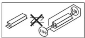
- The light source of this luminaire cannot be replaced. If the light source needs to be replaced (e.g. at the end of its service life), the complete luminaire must be replaced.
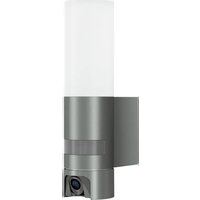
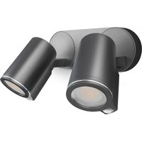
3. RS PRO LED P1 S / FLAT RS PRO LED P2 S / FLAT RS PRO LED P3 S / FLAT
Proper use
- Sensor-switched wall / ceiling light with active motion detector. Limited suitability for outdoor use as a result of detection sensitivity
- Combined emergency light luminaire with single batteries and sensor function which, in compliance with EN 60598-2-22, automatically switches ON an LED emergency light for 3 hours in the event of power failure. (P2/P3)
Note:
When installing, please always allow a distance of at least 3m to Wi-Fi routers or access points.
The integrated HF sensor emits high-frequency electromagnetic waves (5.8 GHz) and receives their echo. The change in echo caused by the slightest movement within the detection zone of the light is detected by the sensor. A microprocessor then issues the switch command "switch light ON". Detection is possible through doors, panes of glass or thin walls.
Note:
The high-frequency power of the HF sensor is approximately 1mW - 1,000 times less than the transmission power of a mobile phone or microwave oven.
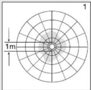
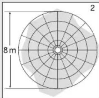
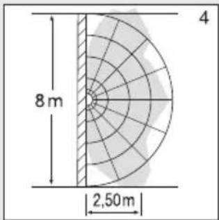
Detection zones for ceiling mounting:
1) Minimum reach (0 1 m)
2) Maximum reach ( 8m)
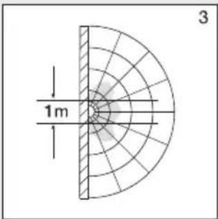
Detection zones for wall mounting:
3) Minimum reach ( 1m)
4) Maximum reach ( 8m)
Package contents for P1 / P1 FLAT / P2 / P2 FLAT (Fig. 1.1 / 1.2)
- Sensor-switched light
-3 spacers
-2 slot-in shrouds
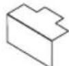
Package contents for emergency light P3 (Fig. 1.3)
- Sensor-switched light
-3 spacers
-2 slot-in shrouds
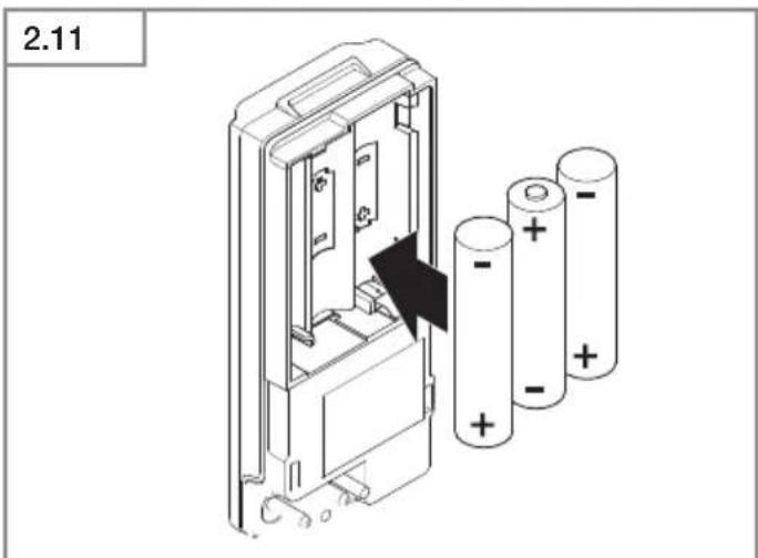
-1 emergency light module (EM)
-3 batteries
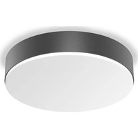
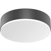
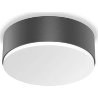
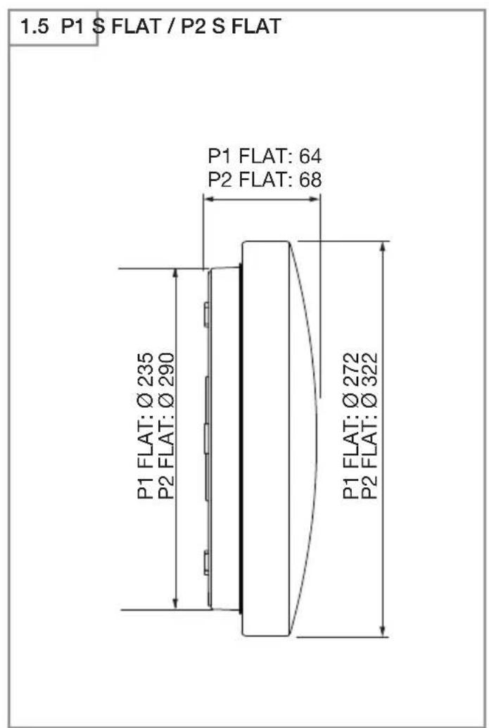
Product dimensions for P1 / P2 / P3 (Fig. 1.4)
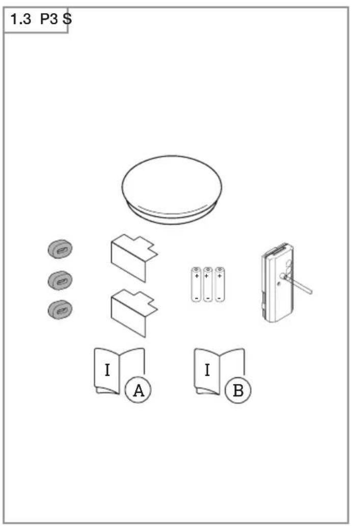
Product dimensions for P1 FLAT / P2 FLAT (Fig. 1.5)
Product components
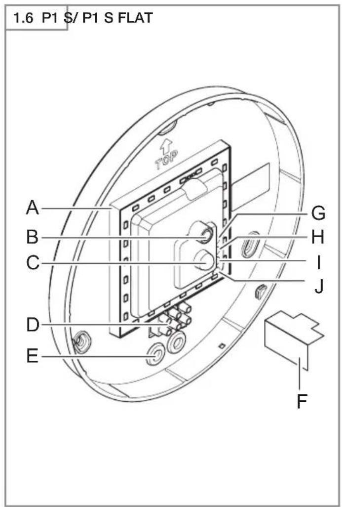
- RS PRO LED P1 / P1 FLAT (Fig. 1.6)
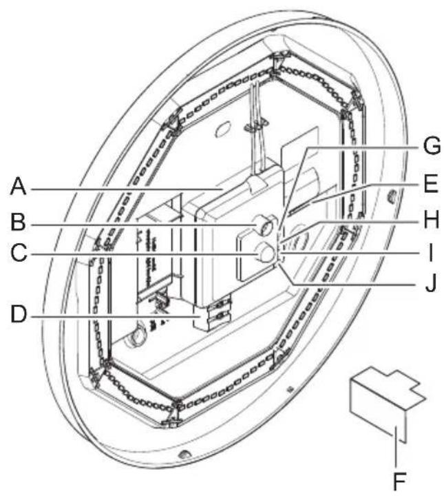
- RS PRO LED P2 / RS PRO LED P2 FLAT / RS PRO LED P3 (Fig. 1.7)
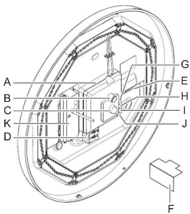
- RS PRO LED P2 emergency light (EM) /
RS PRO LED P2 emergency light (EM) /
RS PRO LED P3 emergency light (EM) (Fig. 1.8)
- RS PRO LED emergency light module (EM) (Fig. 1.9)
A Electronics enclosure
B Light sensor
C HF sensor
D Connecting terminal
E Sealing plug
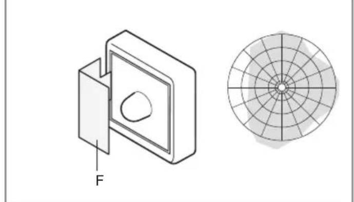
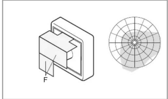
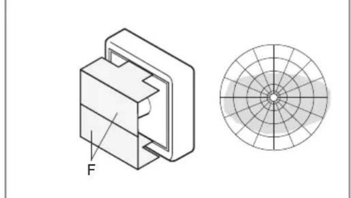
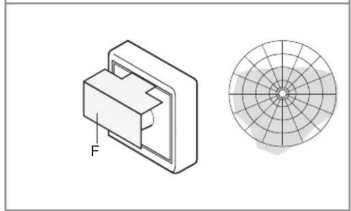
F Slot-in shroud
G Basic light level setting
H Time setting
Reach adjustment
J Twilight setting
K Emergency light module (optional)
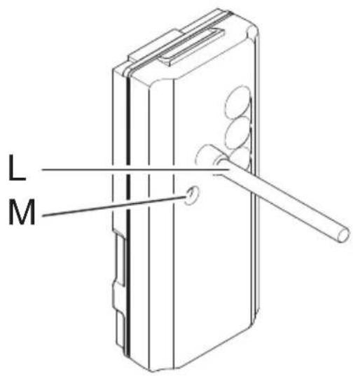
L Status LED
M "test" button
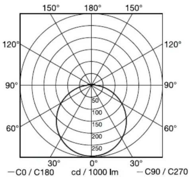
Luminous intensity distribution (Fig. 1.10)
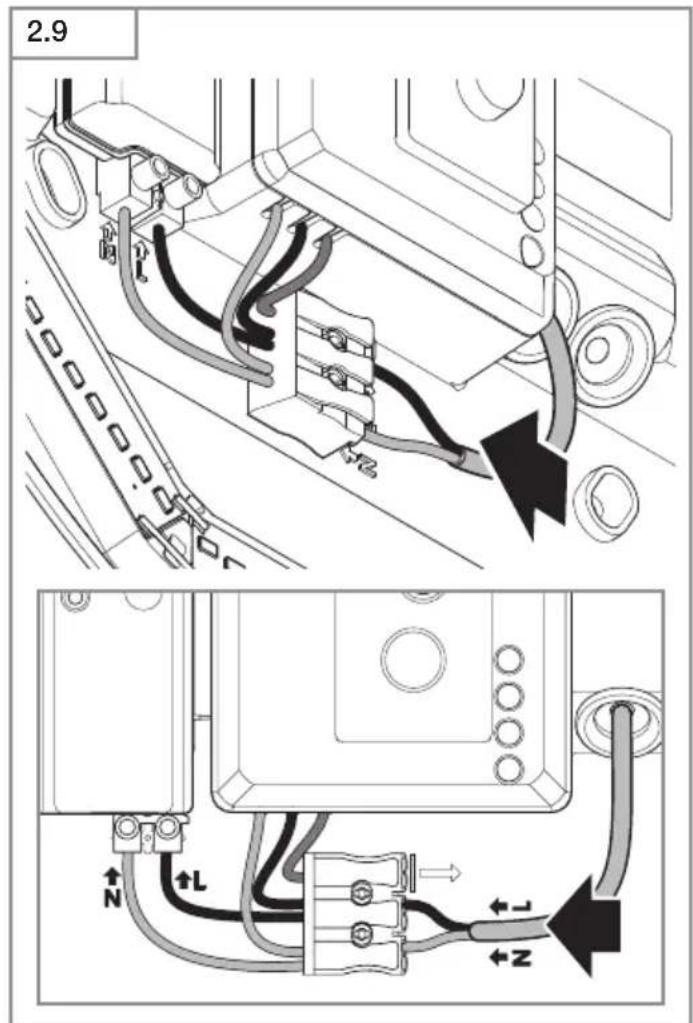
4. Electrical connection
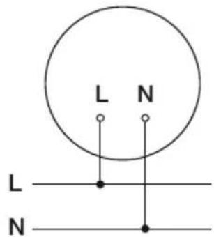
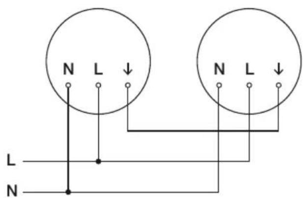
Wiring diagram (Fig. 1.1)
The mains power supply lead is a 3-core cable:
L = phase conductor (usually black, brown or grey)
N = neutral conductor (usually blue)
PE = protective-earth conductor (green / yellow)
= switched phase conductor (usually black, brown or grey)
If you are in any doubt, identify the conductors using a voltage tester; then disconnect from the power supply again.
Connect phase (L), () as well as the neutral conductor (N) to the connecting terminal.
Important:
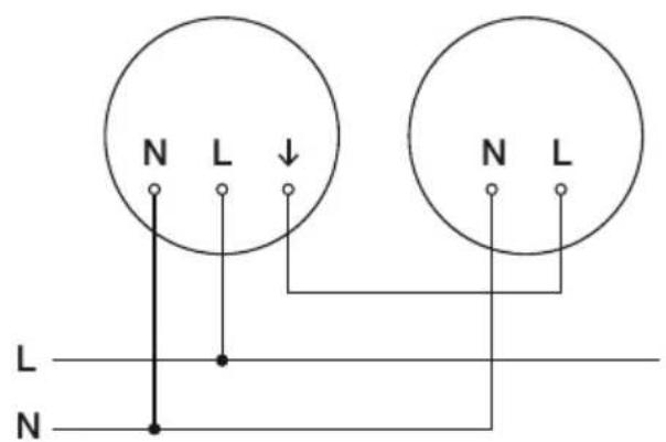
Incorrectly wired connections will produce a short circuit later on in the product or your fuse box. In this case, you must identify the individual conductors once again and reconnect them. A mains power switch for turning the unit ON and OFF may of course be installed in the mains supply lead (in applications without emergency light module).
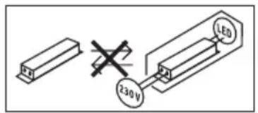
Connection to a dimmer will result in damage to the sensor-switched light.
Note:
Do not make direct contact with the LED.
Note: The light source in this light cannot be replaced. If the light source needs to be replaced (e.g. at the end of its service life), the complete light must be replaced.
5. Mounting
- Check all components for damage.
- Do not use the product if it is damaged.
- When installing the sensor-switched light, make sure the installation site is not exposed to vibration.
-
Select an appropriate mounting location, taking the reach and motion detection into consideration.
-
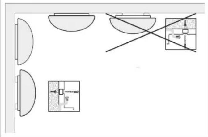
Not suitable for ceiling mounting with surface-mounted power supply lead. (Fig. 2.1)
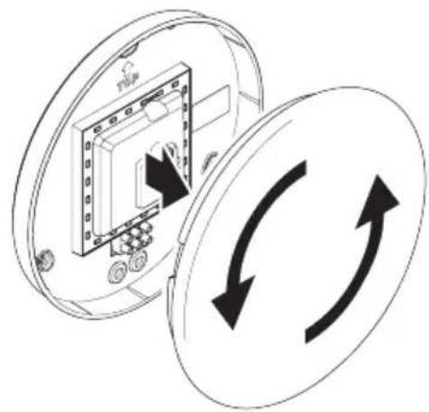
Installation procedure
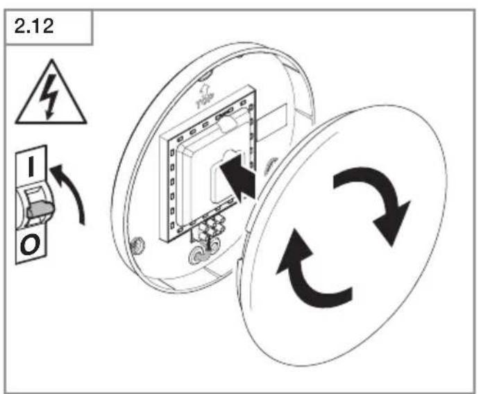
- Switch OFF power supply (Fig. 1.1).
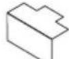
- Detach shade from enclosure (Fig. 2.2).
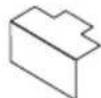
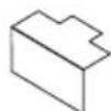
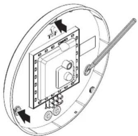
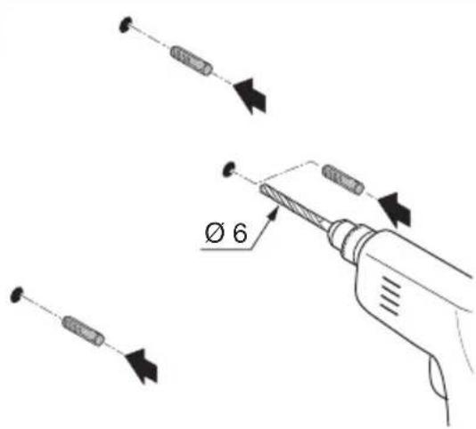
Mark drill holes (Fig. 2.3). - Drill holes and insert wall plugs (Fig. 2.4).
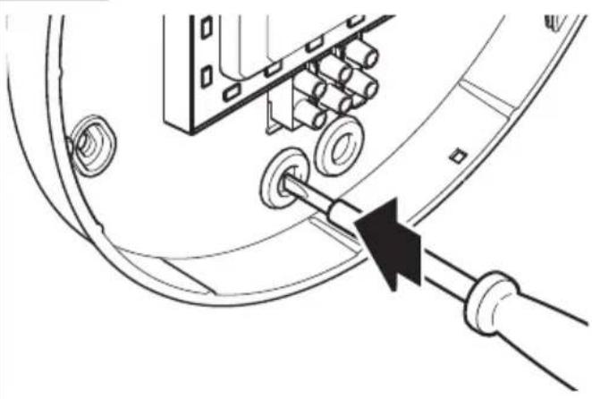
- Pierce sealing plug for power supply lead (Fig. 2.5).
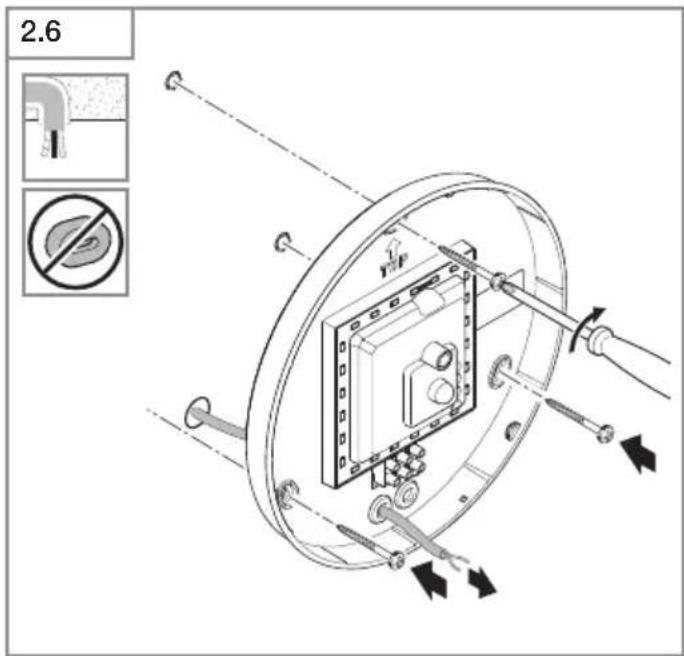
- Installation with concealed power supply lead (Fig. 2.6).
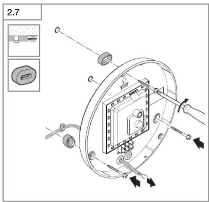
- Installation with surface-mounted power supply lead (Fig. 2.7).
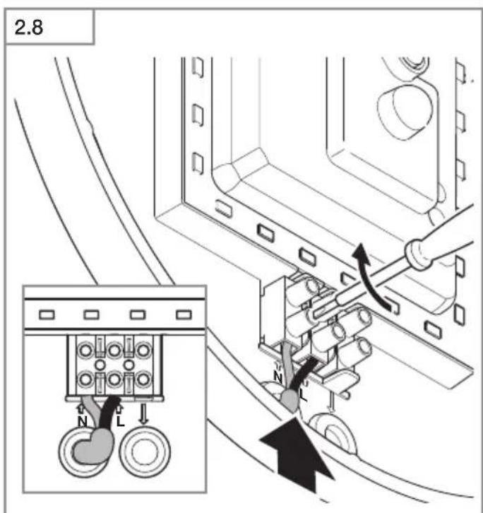
- Connect conductors (Fig. 2.8-2.9).
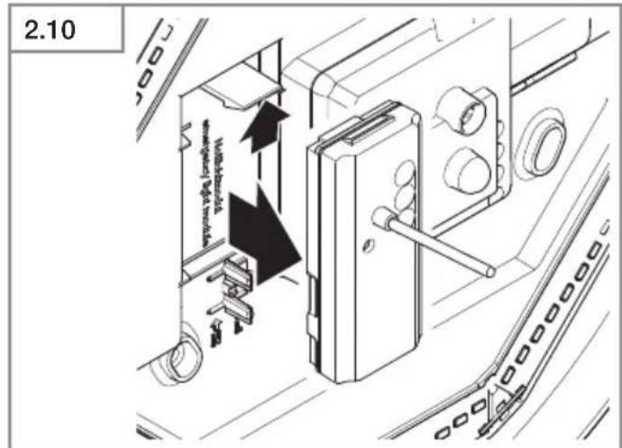
- Remove emergency light module (Fig. 2.10).
- Replace batteries (Fig. 2.11).
- Switch ON power supply (Fig. 2.12).
- Make settings "6. Function".
- Fit shade (Fig. 2.12).
6. Function
Factory settings
Twilight setting 2,000 lux
-Reach setting 8m
- Time setting 5 seconds
- Basic light level function Off
The sensor-switched light can be put into service after mounting the enclosure and connecting to the mains power supply. When putting the light into operation manually at the light switch, it will switch OFF after 10 seconds for the calibration phase and is then activated for sensor mode. It is not necessary to operate the light switch a second time.
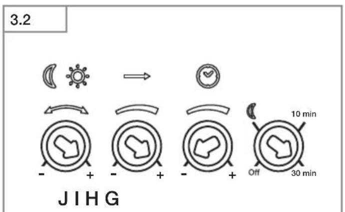
Control dials (Fig. 3.2)
Twilight setting (response threshold) (J)
The chosen response threshold can be infinitely varied from approx. 2 to 2,000 lux.
Control dial set to + = daylight mode (depending on ambient brightness)
- Control dial set to = twilight mode (approx. 2 lux)
The control dial must be turned to + when adjusting the detection zone and performing the functional test in daylight.
Reach setting (sensitivity) (I)
Reach is the term used to describe the diameter of the more or less circular detection zone produced on the ground after mounting the sensor-switched light at a height of 2.5m .
- Control dial + = max. reach of 8 m
- Control dial = reach of 1 m
Time setting (stay-ON time) (H)
The light's ON time can be set to any period from approx. 5 seconds to a maximum of 15 minutes. Any movement detected before this time elapses will restart the timer.
- Control dial set to + = longest time,approx. 15 minutes
- Control dial set to - = approx. 5 seconds
Note:
After the light switches OFF, it takes approx. 1 second before it is able to start detecting movement again. The light will only switch ON in response to movement once this period has elapsed.
The shortest time setting is recommended when adjusting the detection zone and performing the functional test.
Basic light level function (G)
The basic light level function provides illumination at approx. 10% light output when the brightness setting is reached. Movement in the detection zone switches the light ON at 100% brightness for the time selected. Light switches OFF completely after the selected time has elapsed. If the brightness setting has not yet been reached, basic light is switched back ON again.
- Control dial set to = basic light ON
- Control dial set to Off = basic light OFF
- Control dial set to 10min = basic light for 10 minutes
- Control dial set to 30min = basic light for 30 minutes
Basic light is ON when the level of light falls below the brightness threshold. Basic light is always ON when daylight mode is activated. Basic light switches OFF every hour to measure ambient brightness. Basic light switches back ON again after a short period.
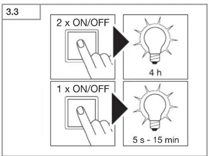
Manual override function
If an optional mains switch is installed in the mains supply lead, the following functions are available in addition to simply switching light ON and OFF:
Manual override (Fig. 3.3)
1) Activate manual override:
Switch OFF and ON twice. The light is set to manual override for 4 hours. Then it returns automatically to sensor mode.
2) Deactivate manual override:
Switch OFF and ON once. Light goes out or switches to sensor operation.
Important:
Switching must take place within 0.2 to 1 second.
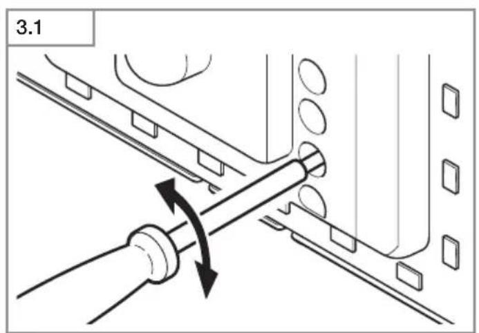
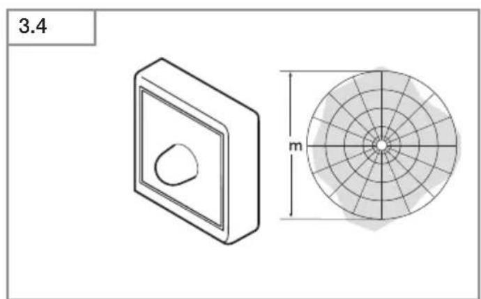
You can reduce reach in four directions by fitting the slot-in shrouds included. (Fig. 3.4)
Operating emergency light module
The emergency light test must always be performed before use.
- Press "test" button, emergency light LEDs ON.
- Release "test" button, emergency light LEDs OFF.
- Optional additional test: disconnect supply from luminaire.
- Emergency light module must switch ON.
- The emergency light module can be changed during normal luminaire operation.
- The status LED must always light up after fitting emergency light module, also when performing emergency light test. The optional additional test (disconnecting from the supply) is no substitute for testing using the "test" button.
Emergency light module malfunctions
Green LED charge indicator not lit:
Emergency light module not properly engaged
- Check mains power connection
- Make sure all rechargeable batteries are fitted and inserted the right way round
Green LED charge indicator ON, emergency light LEDs do not switch ON in response to pressing the "test" button: - Rechargeable batteries very low
- Rechargeable battery cell faulty or fitted the wrong way round
- Check mains power connection
- Make sure rechargeable batteries are fitted the right way round and check state of charge, changing rechargeable batteries if necessary
Green LED charge indicator OFF. On pressing button, switches ON together with emergency light LEDs
- Make sure all rechargeable batteries are fitted and inserted the right way round
Emergency light LEDs immediately go out on pressing the button
- Rechargeable batteries empty or faulty
- Check emergency light module's mains power connection, green LED charge indicator must be lit
7. Accessories (optional)
- Replacement rechargeable battery emergency light module (3 pcs) EAN 4007841 006457
8. Maintenance and care
The product requires no maintenance.
The luminaire can be cleaned with a damp cloth (without detergents) if dirty.
The emergency light luminaire must be serviced at regular intervals in line with national regulations.
Important note: The control gear cannot be replaced.
9. Disposal
Electrical and electronic equipment, accessories and packaging must be recycled in an environmentally compatible manner.

Do not dispose of electrical and electronic equipment as domestic waste.
EU countries only:
Under the current European Directive on Waste Electrical and Electronic Equipment and its implementation in national law, electrical and electronic equipment no longer suitable for use must be collected separately and recycled in an environmentally compatible manner.

Do not throw devices, rechargeable batteries / batteries into household waste, fire or water at the end of their useful life. Rechargeable batteries /
batteries should be collected, recycled or disposed of in an environmentally friendly manner.
For EU countries only:
In accordance with Directive 2006/66/EC, defective or spent rechargeable batteries / batteries must be recycled. Waste rechargeable / non-rechargeable batteries can be returned to the point of purchase or to a collection facility for hazardous substances.
10. Manufacturer's warranty
Manufacturer's warranty of STEINEL GmbH, Dieselstrasse 80-84, DE-33442 Herzebrock-Clarholz, Germany All STEINEL products meet the highest quality standards. For this reason, we, the manufacturer, are pleased to provide you, the customer, with a warranty under the following terms and conditions:
The warranty covers the absence of deficiencies which are proven to be the result of a material defect or fault in manufacturing and which are reported to us immediately after detection and within the warranty period. The warranty shall cover all STEINEL Professional products sold and used in Germany.
Our warranty cover for consumers
The provisions below apply to consumers.
A consumer is any natural person who, on entering into the purchase transaction, neither acts in exercising their commercial nor their self-employed activity.
You can opt for warranty cover in the form of repair or replacement which will be provided free of charge (if applicable, in the form of a successor model of the same or higher quality) or in the form of a credit note.
In the case of sensors, floodlights, outdoor and indoor lights, the warranty period for the STEINEL Professional product you have purchased is: 5 years
for hot-air and hot-melt gluing products: 1 year in each case from the date on which the product was purchased.
We shall bear the shipping costs but not the transport risks involved in return shipment.
Our warranty cover for entrepreneurs
The provisions below apply to entrepreneurs. Entrepreneur is a natural or legal person or partnership with legal personality who or which, on entering into the purchase transaction, acts in exercising their or its commercial or self-employed activity.
We have the option of providing warranty cover by rectifying deficiencies free of charge, replacing a product free of charge (if applicable, in the form of a successor model of the same or higher quality) or by issuing a credit note. In the case of sensors, floodlights, outdoor and indoor lights, the warranty period for the STEINEL Professional product you have purchased is: 5 years
for hot-air and hot-melt gluing products: 1 year in each case from the date on which the product was purchased.
Within the scope of warranty cover, we shall not bear your expenses accruing from subsequent fulfillment nor shall we bear your expenses for removing the defective product and installing a replacement product.
Statutory rights accruing from defects, gratuitousness
The warranty cover described here shall be applicable in addition to the statutory rights of warranty - including special consumer protection provisions - and shall not restrict or replace them. Exercising your statutory rights in the event of defects is gratuitous.
Exemptions from the warranty
All replaceable lamps are expressly excluded from this warranty.
In addition to this, the warranty shall not cover:
- any wear resulting from use or any other natural wear of product parts or any deficiencies in the STEINEL Professional product that are attributable to wear caused by use or other natural wear,
- any improper or non-intended use of the product or any failure to observe the operating instructions,
- any unauthorised additions, alterations or other modifications to the product or any deficiencies attributable to the use of accessory,
supplementary or replacement parts which are not genuine STEINEL parts, - any maintenance or care of products that is not carried out in accordance with the operating instructions,
- any attachment or installation that is not in accordance with STEINEL's installation instructions,
- any damage or loss occurring in transit.
Application of German law
The warranty shall be governed by German law excluding the United Nations Convention concerning the International Sale of Goods (CISG).
Making claims
If you wish to make a warranty claim, please send your product complete and carriage paid with the original receipt of purchase, which must show the date of purchase and product designation, either to your retailer or directly to us at STEINEL (UK) Ltd. - 25 Manasty Road, Axis Park, Orton Southgate, GB- Peterborough Cambs PE2 6UP United
Kingdom. For this reason, we recommend that you keep your receipt of purchase in a safe place until the warranty period expires.

11. Declaration of Conformity
Hereby, STEINEL GmbH declares that the radio equipment typeRS PRO LED P1/RS PRO LEDP2/RS PRO LED P3 is in compliance with Directive 2014/53/EU. The full text of the EU declaration of conformity is available at the following internet address: www.steinel.de
12. Technical specifications
| Dimensions (Ø x D) P1 S: Ø 280 x 10 mm P2 S: Ø 320 x 120 mm P3 S: Ø 400 x 142 mm | P1 S FLAT: Ø 272 x 64 mm P2 S FLAT: Ø 322 x 68 mm | |
| Supply voltage 220-240 V, 50/60 Hz | ||
| Material PMMA (shade) | ||
| Power consumption (Pon) P1 S: NW | 9.40 W P1 S: WW: 9.40 W P2 S (EM) NW: 15.40 W P2 S (EM) WW: 15.10 W P3 S (EM) NW: 18.40 W P3 S (EM) WW: 18.40 W | P1 S FLAT NW: 9.40 W P1 S FLAT WW: 9.40 W P2 S (EM) FLAT NW:15.40 W P2 S (EM) WW:15.10 W |
| Standby sensor (Psb) 0.39 0.39 | ||
| Mains current | P1 S: 230 V-45 mA P2 S: 230 V-75 mA P3 S: 230 V-88 mA | |
| Power factor P1 S: 0.91 | P2 S: 0.91 P3 S: 0.93 | |
| Additional switching capacities Filament bulb / halogen load 800 W LED / ECG load: 250 W (50 pcs. c < 88 μF) | ||
| Luminous flux (360°) P1 S NW: 980 | Im P1 S WW: 953 lm P2 S (EM) NW: 1,731 lm P2 S (EM) WW: 1,674 lm P3 S (EM) NW: 2,188 lm P3 S (EM) WW: 2,072 lm | P1 S FLAT NW: 965 lm P1 S FLAT WW: 942 lm P2 S (EM) FLAT NW: 1,700 lm P2 S (EM) FLAT WW: 1,608 lm |
| Efficiency P1 S NW: 104 lm/W | P1 S WW: 101 lm/W P2 S (EM) NW: 112 lm/W P2 S (EM) WW: 110.90 lm/W P3 S (EM) NW: 119 lm/W P3 S (EM) WW: 112.60 lm/W | P1 S FLAT NW: 102.70 lm/W P1 S FLAT WW: 100 lm/W P2 S (EM) FLAT NW: 110 lm/W P2 S (EM) FLAT WW: 106.50 lm/W |
| Luminous flux, emergency light 38 lm | ||
| Colour temperature PMMA 4,000 K | (neutral white = NW) Glass 3,000 K (warm white = WW) | |
| Colour rendering index R | a=82 | |
| Average rated life expectancy L70B50 at 25 °C: 60,000 hours | ||
| Colour consistency SDCM SDCM 3 | ||
| Luminous intensity distribution | ||
| HF technology 5.8 GHz (responds to the slightest movement regardless of temperature) | ||
| Angle of coverage 360° with 160° angle of aperture | ||
| Transmitter power approx. 1 mW | ||
| Reach Ø 1–8 m | ||
| Time setting | 5 s–15 min | |
| Basic light level | 10 % | |
| Twilight setting | 2–2,000 lux | |
| IP rating | IP54 | |
| Protection class | II | |
| Temperature range | -10 to +40 °C | |
| Energy efficiency class | P1 S: D P2 S: D P3 S: D | P1 S FLAT NW: E P1 S FLAT WW: E P2 S FLAT NW: D P2 S FLAT WW: D |
13. Technical specifications - rechargeable batteries
3 × Panasonic NiMh, HHR 80AAAB, 1.2 ~V / 750 mAh , AAA
Batteries permanently charged at approx. 23mAh generating no heat
Charging time: 24h (permanently connected to mains power)
Rechargeable battery capacity / emergency lighting duration: at least 3 h ^* *
^1) Maximum capacity only ensured by using rechargeable batteries provided.
Important: Rechargeable batteries must be replaced if the emergency light module stays ON for less than 3 h.
14. Troubleshooting - sensor-switched light
Malfunction Cause Remedy
| Sensor-switched light without power | ■ Fuse has tripped, not switched ON, break in wiring | ■ Activate, change fuse, turn ON mains switch, check wiring with voltage tester |
| ■ Short circuit in mains power supply lead | ■ Check connections | |
| ■ Any mains switch OFF | ■ Switch on mains switch | |
| Sensor-switched light will not switch ON | ■ Wrong twilight setting selected | ■ Reset |
| ■ Mains switch OFF | ■ Switch ON | |
| ■ Fuse has tripped | ■ Activate, change fuse, check connection if necessary | |
| Sensor-switched light will not switch OFF | ■ Continued movement within the detection zone | ■ Check detection zone |
| Sensor-switched light switches ON without any identifiable movement | ■ Light not mounted for detecting movement reliably | ■ Securely mount enclosure |
| ■ Movement occurred, but not iden- tified by the observer (movement behind wall, movement of a small object in immediate lamp vicinity etc.) | ■ Check detection zone | |
| Sensor-switched light does not switch ON despite movement | ■ To minimise malfunctioning, rapid movements are suppressed or detection zone too small | ■ Check detection zone |
| ■ Wrong twilight setting selected | ■ Reset |
15. Troubleshooting - emergency light module
Malfunction Cause Remedy
| Green charge indicator LED not lit | ■ Emergency light module not properly engaged ■ No supply voltage ■ Emergency light LEDs faulty | ■ Check mains power connection ■ Replace rechargeable batteries ■ Make sure all rechargeable batteries are fitted and inserted the right way round |
| Green charge indicator LED ON, emergency light LEDs do not switch ON in response to pressing the button | ■ Rechargeable batteries very low ■ Rechargeable battery cell is faulty | ■ Check mains power connection ■ Make sure rechargeable batteries are fitted the right way round and check state of charge |
| Green charge indicator LED OFF. On pressing button, switches ON together with emergency light LEDs | ■ Not all rechargeable batteries fitted or rechargeable batteries inserted the wrong way round | ■ Make sure all rechargeable batteries are fitted and inserted the right way round. If necessary, replace rechargeable batteries |
| Emergency light LEDs immediately go out on pressing the "test" button | ■ Rechargeable batteries empty or faulty | ■ Check emergency light module's mains power connection, green charge indicator LED must be lit |
FR
RS PRO LED P3 nodlys (EM) (ill. 1.8)
- RS PRO LED nodlysmodul (EM) (ill. 1.9)
A Elektronikkhus
B Lyssensor
C HF-sensor
D Koblingsklemme
E Tetningsplugger
F Dekkplate
G Grunnlysinnstilling
H Tidsinnstilling
1 Rekeviddeinnstilling
J Skurringsinnstilling
K Nodlysmodul (ekstrautstyr)
L Status-LED
M Knapp «Test»
Permanent lys (ill. 3.3)
1) Tenne permanent lys:
3 ks Panasonic NiMh, HHR 80AAAB,1,2 V/750 mAH, AAA
Permanentn nabijeni akumulatoru s asi 23 mAh, nedochazi k vlastnimu zahrviani
Doba nabijeni: 24 hod. (trvalé sitóve napěti)
3 ks Panasonic NiMh, HHR 80AAAB,1,2 V/750 mAH, AAA
Dlhodobé nabijanie akumulátora pomocou cca 23 mAh, bez zahrievania
Doba nabijania: 24 hodin (stale sie'tove napatie)
- PerynaTop + = MaKcImMaJIeH 06XbaT 8 M
- PerynaTop - = MHHMaJIeH o6XBaT 1 M
Hactpoika Ha BpeMeTo (BpeMe Ha donbJIHNTeJHO ocBeTBAHe) (H)
XeIaHaTa npoBnKInTeHOCHT Ha CBeTHe Ha IaMnata MoKe da ce peryuipa 6e3cTeHNO OT OKOLO 5 cekHydi Do MaKc.15 MInHyTu. BcKaO 3aceYeHO DmXKeHne IpedeNtTuHa He Ha BpeMeTo BpbUa YacOBHnKa B IIbPBOHaaHa HIO3NlUy.
- Perynatop + = OKOIO 15 MInHyTN
- Perynatop = okolio 5cekyHn
CbeHne:
CneB BcraKO N3KJIIOHbAHe Ha JIaMnTa 3acuHaHTO Ha HOBN DnBXKeHnCe npeKbcBa 3a OKo1 OceHyda. EJBa CneT TOBa JIaMnTa MoKe Da Ce BKJIIOHn npN 3aceYeHO DnBXKeHnE.
Pn HacpoKa Ha 0xbaTa n 3a npOBepKa Ha fynKunTe ce npenopbUba Da 6bJe N36paH Na-KpaTkn INHTepBaJ.
Функця OCHOBHOOCBeTneHnE (G)
Функцяпа OCHOВHA CBETЛИнhaДаВа ВьзMOXHOCHT3a OCBETЛЕнe COKO NO 10% OT CBETЛINHаTAMOLHOCCT, KOrato6bIe DOCTUNHAT HAcTPOEHnIЯpar Ha OCBETHOCT.ПиДвИЖЕНe BOBXBaTA CBETЛINHATAce BKJIIOYBa 3aИЗбpaHnB BPemEBN INTEpBaI cbc 100%MOUHOCCT.CNeId n3TNuAHeHa HAcTPOEHOTOBpeMe CBETЛINHaTa ce N3KJIIOUByHaHbJIHo.AKO HAcTPOEHnIЯpar Ha OCBETEOCT BCE OUIe e HAnxBbPJIeH, OCHOBHaTACBTЛINa OTHOBoCE BKJIIOUBA.
- Perynatop Ha C = OCHOBHa CBetTnHa BKJI
- Perynatop Ha Off = oCHOBHa CBeTJnHa I3KJI
- PerynaTop Ha 10 MmH = oCHOBHa CBeTNIHa 10 MmHyTu
- Perynatop Ha 30 MmH = oCHOBHa CBeTmHa 30 MmHyTN
OchOBHaTa CBETnHa e BKJI, KOraTo npara Ha OCBeTeHOCT 6bJe NOIMHaT. IprnakTNBipan DHeBEH peKIM OCHOBHaTa CBETnHa BINHar e BKJI. OChOBHaTa CBETnHa ce N3KJIIOvBa Ha BCEKn Yac, 3a Da IN3Mepn OKJInHaTa OCBeTeHOCT. CLei KpaTKO BpeMe OCHOBHaTa CBETnHa OTHOBO Ce BKIIIOvBa.
ФУHKUЯ NOCTOHA CBETNHa
AkoOnuHOHaJIHO6bIeBKJIIOHeHnpEkbBaU,OCBeH BKIOHaBe Hn3KIOOBAHe,CaBb3MOxHN CJIeHNITe 1yHKcN:
NoctoHHa CBetHnHa (pnc. 3.3)
1) BkIIOUbaHe nocToHHa CBETnHa:
7aTep 2 × N3KNI BKN. Iamnata octaba c noctoHHa CBETJInHa 3a 4aca.Cnei TOBa aBTOMaTHHO npemHaba OTHOB CEHOpE hpeKM.
2) N3KJIIOUbaHe Ha NOCTOHHa CBETINHa:
waTep 1 x N3KJI n BKJI. lamnata ce n3KJIIOyBa, CbOTBeTHO IpeMnHaBA B CEH3OpEN peXIM.
BaxHo:
BkIIOUBaHnra Ta Tp6Ba Da ce n3BbPbBaT 3a 0,2 do 1cekyHa.
C nocTaBnHe Ha npInIOxKeHnTe 6IeHNi, 06XBaTbT MoXe Da 6bJe HamaJIe H YeTInpn NOCOKn. (pnc.3.4)
06cnykBaHe MdyI 3a aBapnHa CBETnHa
Ipeynyntpe6a abapnHOTOCBETJIeHne 3aNbJXHTeHNO da ce TectBa.
- HatncheTe 6yToH „test", abapnHnTe LED ce BKIOuBaT.
- NychTe 6yToH ,test", abapnHnTe LED ce n3KJIIOHBaT.
- OnuHaleH DonbHHTeH Tect: 3axpaHbaHeTo da ce OTdeJN OT lamnata.
- MoDynt3a abapnHa CBetJInHa Tpr6Ba da ce BKJIIOH.
MoynbT 3a abapnH0 OCBETHeHne MOKe Ja Ce CMeHr NO BpeMe Ha HopMaJIHaTa pa6Ota Ha JAmnata. - KoHTpoHnIyT LED TpR6Ba BnHaN Da CBeTn Cnei H3PON3BaHe Ha MOnyJNa 3a abapNHO OCBETHe, DOpN npN pNoBExKaHe Ha TeC. ONUHOHaHnIyT DObJIHNTeHe TcE, OTdJIeHr He 3axpaHbHeTo, He 3ameCTBa npOBepKaTa npe3 ByToHa "test".
Pp6JIeMn C MoyUa 3a aBapuHa CBETINHa
3eHHT LED-noka3aTeJ 3a 3apeKdaHe He CBetI:
MoynbT 3a abapnHa CBetInHa He e nocTaBeHdo6pe
-Да се повери врьзката с мрекатa
-Да ce npobepи посokataи Бpoя На batepinte
3eHHT LED-nokaateJ 3a 3apeXJaHe CBETn, abapn HHTe LED He ce BKJIIOvBaT c 6yToHa "test":
- BaTePmIte ca TBbpDe pa3peJeH
- BaTepeTAte e depeKTHa nI rpeSho nocTaBeHa
Ja ce npoBepn Bpb3kata CmpekaT
-Да ce npOBepn NocOKaTи 3apeHocTtHa 6aTePmTe, eBeHTyaJIHO da ce 3aMeHrT
3eHnTLED3a3apeKdahe He CBeTN, BkIIOUba ce 3aeHo c abapuHnTe LED npn HATNcKaHe Ha 6yToH
-Да се повери посokату и бpoя на застпerte
PnHaTnCKaHe Ha 6yToHa abapuHHTe LED BeHara ce n3KJIIOUbAT
- BaTepeHnTe ca npa3Hn nJIn DepeKTHn
-Да ce npOBepn BpB3kaTa Ha MOnyla 3a abapuHa CBetTInHa, 3eJIeHnT LED 3a 3apeXdaHe TpI6Ba da CBETN
BaxHo: ypeTbT He MoXe da 6bDe 3aMeHraH.
9.Отствае
EneKtpoypei, npHaIeXHocTn n OaKOBKn Tp6Ba Da 6bDaT peuKlnpaHn, c cen ona3BaHe Ha OKoJHaTa Cpeia.

He n3xBpbIyIe enekTpoypeNi c obuIte domaHn OTnabcu!
Cama 3a cTpaHn ot EC:
CnopeIeIcTBaUaTa DnpeKtNbHa Ha EC 3a cTapu eJeKtpoHn I eJeKtpOyPeDn I TpaHCNoHnpaHTo N B HauHOHaJIHO npABO, eJeKtpOyPeDn, KOIT O nobYe He Mo- rat Da bBdA t yNtpe6BaHn, Tpr6Ba Da bBdA t pa3deJHo Cb6ipAHn I peuiklnpAHn, C ceI Opa3BaHe Ha OKoJHaTa cpeA.

He n3xBpIyTe cTapn ypeN, akymyataOpn/ 6aTePNB O6U7 60KlyK, BOrbH NIN BB BOba.
AkymynaTopn/6aTeepnn Tpr6Ba Da ce cb6npaT,
HpaT nn Da ce OCTpaHraBt no IpeDna3BaU, 3a,
Ta CpeDa HauHH.
Cama 3a cTpaHn ot EC:
CnopeI DnpeKtnBa 2006/66/EO DepeKTHn IIN IN3ToUeHN
akymlaTopn/6aTeepn Tp8Ba da 6bDaT peuKnIpaHn
AkyMnaTopn/6aTeepn, HeroDn 3a yNoTppeBa, MoTa Da
6bDaT BbpHaTn Ha TbProBeua IIN B nYHKT 3a CbBipaHe
Ha BpeHN OTNaDbU.
10. rapaHcna OT npOn3BODnteJIa
Bpojra Bn Ha KnyBa pa3noIarate cbc 3akoHOBN npaba cnpraMo npoDaBaay. Ako Te3n npaba CbIeCTByBat BB BaWata CTpaHa, Ta3n rapaHIOHHa JeKJIapauu Hr n OrpaHnUaBA, HnTo rCbKpauaBA. Hne BN daBaMe
5 roHn npaHn 3a nepfkeTHa n3pa6Oka n npaBnHO fynKIOHnpaHe Ha Baun npOyKT STEINEL-Professional -OT cepnra CeH3OphA Texnka. Hne rapaHTnpame, ye To3n npOyKT Hma MaTePnAHN, pOn3BOJCTBeHn I KOHCTpykTNBn HeoCTaTbU. Hne rapaHTnpame yHKIOHAnHOCTTa Ha BCNUeEKeTPOHH eMeMeHTn I Ka6JI, KaKTo N JInCaTa Ha DepeKtB IN3NoI3BaHNTe MaTePnAIn N TEXHnTE NOBbPxHOCTn.
「apaHnHOHeN NCK:
Ako nckate da Hapabnte peKlaMaunna Ha Baunna
npodykt,MOJI Da FO I3npaNTte HaTbJIHO OKOMnKeTObAH
H 3a Ha7a CmETka,3aeNHO C oprHaJHaTa Kacoba
6eJekKa nnI paKtpya, KOITTO Tp8Ba Da CbIbPkaT
daTata Ha NOKyPkata N O6O3NaHeHneTo Ha npOyKta,
Ha Baunra TbProBeu nnI DnpeKTHo Ha HAC, TALUEB-
TALBNIHr OOD,Byn.KImeHT OxpiDcKn Ne 68,1756
CoFna, Bblrapna. 3aT0Ba BN npenopbVbame rpnKlnBO
da Na3nte KacOBATA 6eJekKa nnI paKtypata Do n3TuHahe
Ha rapaHNoHHn cPok. 3a Uetn HAcTbnInn no Bpeme Ha
TpaHcnopTa Ha npOdykTa STEINEL He noema OTROBOPHOCT.
HOpMaIg 3a npedctabRe He rapaHIOHe NCK Ie. noJyHTe Ha HaaTa INTEpHET cTpaHnla www.tashev-galving.com
Ako imate rapaHIOHOEN clyaH NIN Bbnpoc NO Baunn npOyKT, MoKeTe Da HN Ce oBaNTe NO BCaKO BpeMe Ha Naunr cepBn3eH Tenepon +359 (2)700 45 454.

TOJHNAI
OTYPOM3B0DMTER
11.ДeКларачnia 3a CbOTBETCTBNE
C hactoJIoTo STEINEL GmbH deKnapipa, Ye To3n TINI paIOocbOpBXeHne RS PRO LED P1 S / RS PRO LED P1 S FLAT / RS PRO LED P2 S / RS PRO LED P2 S FLAT / RS PRO LED P3 SeB cbOTBeTCTBnE c DInpeKtNbA 2014/53/EC. LJIIOCTHnRT TekCT Ha EC deKnapaunraTa 3a cbOTBeTCTBnE MOKe da ce HamepHa cnEHHN INHTepHET aIpec: www.steinel.de
12. TexHnueckn daHHN
| P1 S / P2 S / P3 S FLAT / P2 S FLAT | ||
| Размери (Ø x Д) | P1 S: Ø 280 x 110 MM P2 S: Ø 320 x 120 MM, P3 S: Ø 400 x 142 MM | P1 S FLAT: Ø 272 x 64 MM P2 S FLAT: Ø 322 x 68 MM |
| Зхранвае220-240 V, 50/60 Hz | ||
| Мaterия | PMMA (покрivaц калak) | |
| Консуmp再一次 мошност (Por) P1 S | NW: 9,40 W P1 S: WW: 9,40 W P2 S (EM) NW: 15,40 W P2 S (EM) WW: 15,10 W P3 S (EM) NW: 18,40 W P3 S (EM) WW: 18,40 W | P1 S FLAT NW: 9,40 W P1 S FLAT WW: 9,40 W P2 S (EM) FLAT NW:15,40 W P2 S (EM) WW:15,10 W |
| Standby сени (Psp) 0,39 0,39 | ||
| Мразков тok | P1 S: 230 V-45 mA P2 S: 230 V-75 mA P3 S: 230 V-88 mA | |
| Мошостен phастор | P1 S: 0,91 P2 S: 0,91 P3 S: 0,93 | |
| Довл致电лел мошносту | Мошност обикноеви/халогени лamпи 800 W Натоваране на LED/EVG: 250 W (50 sp. c < 88 μF) | |
| Светлиен поtok (360°) | P1 S NW: 980 lm P1 S WW: 953 lm P2 S (EM) NW: 1.731 lm P2 S (EM) WW: 1.674 lm P3 S (EM) NW: 2.188 lm P3 S (EM) WW: 2.072 lm | P1 S FLAT NW: 965 lm P1 S FLAT WW: 942 lm P2 S (EM) FLAT NW: 1.700 lm P2 S (EM) FLAT WW: 1.608 lm |
| Ефektivност | P1 S NW: 104 lm/W P1 S WW: 101 lm/W P2 S (EM) NW: 112 lm/W P2 S (EM) WW: 110,90 lm/W P3 S (EM) NW: 119 lm/W P3 S (EM) WW: 112,60 lm/W | P1 S FLAT NW: 102,70 lm/W P1 S FLAT WW: 100 lm/W P2 S (EM) FLAT NW: 110 lm/W P2 S (EM) FLAT WW: 106,50 lm/W |
| Светлиен по tok abарийся светлиа | 38 lm | |
| Темпера typа на цета | PMMA 4.000 K (néуtrално бял = NW) Съknlo 3.000 K (топлно бял = WW) | |
| Иndек на цетовото оtripожения | Ra=82 | |
| Среда пюдьгіптоност на жibот | L70B50 рп 25 °C: 60.000 ча | |
| Консystения на цета SDCM | SDCM 3 | |
| Раз畴endeленnes на сvetлиаftera | ||
| Високочецегда на сvetлиаftera | 5,8 GHz (peага на най-малкite д辊жени, независимо отtemпера typа) | |
| Бгл на очинке | 360° c 160° Бгл на разовр | |
| Изльчваши мошноct | okoно 1 mW | |
| Оьхbat Φ 1-8 M | ||
| Настойка на врemeeto | 5 с.-15 мин. | |
| Базово осветлике | 10 % | |
| Настойка наSBETLOЧВСВITEЛHOCCTTA | 2-2.000 Lux | |
| Вид зашитAlP54 | ||
| Клас зашитall | ||
| Temператуpen дианалазон | -10 do +40 °C | |
| Клас сеоргийницеktivhoect | P1 S: D | P1 S FLAT NW: E |
| P2 S: D | P1 S FLAT WW: E | |
| P3 S: D | P2 S FLAT NW: D | |
| P2 S FLAT WW: D | ||
13. TexHnueckn daHHn 6aTeepnn
36poI Panasonic NiMh, HHR 80AAAB, 1,2 V/750 mAH, AAA
3apeKdaHe Ha 6aTePmnte c OKoJIO 23 mAh nocToHNO, He ce cb3daBa co6CTBeHO 3aFpaHe
Bpeme 3a 3apexdahe: 24 yaca (npodbIjKnteJIHO mpeXko HappeXeHne)
KanaTETnpoDbJnxHIOCTHaabapnHOTOCBETJeHHe:nohe3yaca
^1) MaKcImaJIHnIaT KaIauITeT ce rapaHTnpa cAmO aKO ce n3NON3BaT npuIOXeHInTe 6aTePM.
Baxho:Korato npoDbJnxHIOCTTa Ha OCBETBaHe OT MOyla 3a abapnHO OCBETIeHne naHne no3 yaca, bATEpntTe Tpa6Ba da 6bDat 3ameHEn.