
PKS 1500 B3 - Electric saw PARKSIDE - Free user manual and instructions
Find the device manual for free PKS 1500 B3 PARKSIDE in PDF.
| Product type | Pendulum miter saw (radial arm saw) |
| Brand | Parkside |
| Model | PKS 1500 B3 |
| Supply voltage | 220-240 V ~ |
| Frequency | 50 Hz |
| Rated power (S1) | 1200 W |
| Max. power (S6 25%) | 1500 W |
| No-load speed | 5000 min⁻¹ |
| Saw blade (diameter x bore x thickness) | 210 x 30 x 2.6 mm |
| Number of teeth | 48 |
| Cutting width at 90° | 120 x 60 mm |
| Cutting width at 45° | 80 x 60 mm |
| Cutting width at double miter | 80 x 35 mm |
| Inclination range | -45° / 0° / +45° |
| Miter range | 0° to 45° left |
| Weight | approx. 7.6 kg |
| Protection class | II (double insulation) |
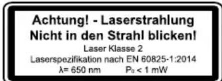
| Laser class | 2 |
| Laser wavelength | 650 nm |
| Sound pressure level LpA | 99.6 dB |
Frequently Asked Questions - PKS 1500 B3 PARKSIDE
User questions about PKS 1500 B3 PARKSIDE
0 question about this device. Answer the ones you know or ask your own.
Ask a new question about this device
Download the instructions for your Electric saw in PDF format for free! Find your manual PKS 1500 B3 - PARKSIDE and take your electronic device back in hand. On this page are published all the documents necessary for the use of your device. PKS 1500 B3 by PARKSIDE.
USER MANUAL PKS 1500 B3 PARKSIDE
Operating and Safety Instructions.
Translation of Original Operating Manual
FR BE CH
SCIE A ONGLET
NAGIBNA PREKLOPNPA PILA
Upute za posluživanje i za Vasu sigurnost. Prijevod originoh uputa za uporabu

HACTOJEHUNPKUYIAP
Hnctpykun 3a o6cnyjBahe n 6e3onachoct. PpeboHa opurnhno To pkoBocTbO 3a ekCnnoatau
AT CH
Before reading, unfold the page containing the illustrations and familiarise yourself with all functions of the device.
DE AT CH
- Explanation of the symbols on the equipment 2
- Introduction 3
- Device description (fig. 1-16)
- Scope of delivery 4
- Proper use 4
- Safety information 4
- Technical data 9
- Before commissioning 9
- Attachment and operation 10
- Transport (fig. 13) 13
- Maintenance 14
- Storage 14
- Electrical connection 14
- Disposal and recycling 15
- Troubleshooting 16
- Warranty certificate 17
- Exploded view 298
- Declaration of conformity 300
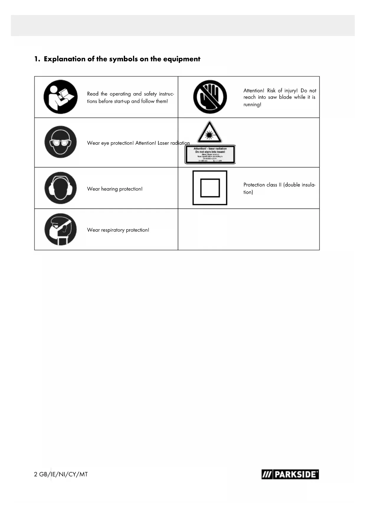
1. Explanation of the symbols on the equipment
| Read the operating and safety instruc-tions before start-up and follow them! | Attention! Risk of injury! Do not reach into saw blade while it is running! |
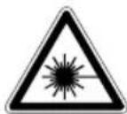
| Wear eye protection! Attention! Laser radiation | Attention-laser radiation Do not stare into beam! do not wear protective wear mask according to EN 60028-1 |
| Wear hearing protection! | Protection class II (double insula-tion) |
| Wear respiratory protection! |
2. Introduction
Manufacturer:
Scheppach GmbH
Günzburger Straße 69
D-89335 Ichenhausen
Dear customer,
We hope your new tool brings you much enjoyment and success.
Note:
In accordance with the applicable product liability laws, the manufacturer of this device assumes no liability for damage to the device or caused by the device arising from:
- Improper handling,
- Failure to comply with the operating instructions.
- Repairs carried out by third parties, unauthorised specialists.
- Installing and replacing non-original spare parts,
Application other than specified, - Failure of the electrical system in the event of the electrical regulations and VDE provisions 0100, DIN 57113 / VDE0113 not being observed.
Please consider:
Read through the complete text in the operating manual before installing and commissioning the device.
The operating manual is intended to help the user to become familiar with the machine and take advantage of its application possibilities in accordance with the recommendations. The operating manual includes important instructions for safe, proper and economic operation of the device, for avoiding danger, for minimising repair costs and downtimes, and for increasing the reliability and extending the service life of the device.
In addition to the safety instructions in this operating manual, you must also observe the regulations applicable to the operation of the device in your country.
Keep the operating manual package with the machine at all times and store it in a plastic cover to protect it from dirt and moisture. They must be read and carefully observed by all operating personnel before starting the work.
The device may only be used by personnel who have been trained to use it and who have been instructed with respect to the associated hazards. The required minimum age must be observed.
In addition to the safety instructions in this operating manual and the separate regulations of your country, the generally recognised technical rules relating to the operation of such machines must also be observed.
We accept no liability for accidents or damage that occur due to a failure to observe this manual and the safety instructions.
3. Device description (fig. 1-16)
- On/off switch
- Locking switch
- Handle
- Machine head
- Moving saw blade guard
- Saw blade
- Set screw for rotary table
- Stop rail
8a. Moveable stop rail
8b. Locking screw - Fixed saw table
- Table insert
- Scale
- Pointer
- Rotary table
- Set screw for workpiece support
- Clamping device (workpiece clamp)
- Locking screw
- Dust bag
- Workpiece support
- Locking screw for clamping device
- Locking screw for drag guide
- Stand bracket
- Adjusting screw (45°)
22a. Locknut adjusting screw (45°) - Locking screw
- Clamping handle
- Locking pin
- Adjusting screw (90°)
26a. Locknut adjusting screw (90°) - Scale
- Pointer
- Flange screw
- Outer flange
- Guide bar
- Sawing shaft lock
- Laser ON/OFF switch
- Battery cover
-
Laser
-
Screw (laser)
- Transport handle
(A) 90° stop bracket (not included in the scope of delivery)
(B) 45° stop bracket (not included in the scope of delivery)
(C) Allen key, 6 mm
(D) Allen key, 3 mm
(E) Phillips head screw (table insert)
4. Scope of delivery
Cross-cut litre saw
- Dust bag
- Workpiece clamp
- Allen key, 6 mm (C)
- Allen key 3 mm (D)
- 2x workpiece supports
- Stand bracket
- 2x carbon brushes
- 2x batteries (AAA)
- Operating manual
5. Proper use
The mitre saw is used for the cutting of wood and plastic, according to the machine size. The saw is not suitable for the cutting of firewood.
Warning!
Do not use the device to cut materials other than those described in the operating manual.
Warning!
The supplied saw blade is only intended for the sawing of wood! Do not use this blade for sawing firewood!
The machine may only be used in the intended manner. Any use beyond this is improper. The user/operator, not the manufacturer, is responsible for damages or injuries of any type resulting from this.
Only suitable saw blades may be used for the machine. The use of any type of cutting wheels is prohibited.
An element of the intended use is also the observance of the safety instructions, as well as the assembly instructions and operating information in the operating manual.
Persons who operate and maintain the machine must be familiar with it and must be informed about potential dangers. In addition, the applicable accident prevention regulations must be strictly observed.
Other general occupational health and safety-related rules and regulations must be observed.
The liability of the manufacturer and resulting damages are excluded in the event of modifications of the machine.
Despite use as intended, specific risk factors cannot be entirely eliminated. Due to the design and layout of the machine, the following risks remain:
- Contact with the saw blade in the exposed sawing area.
- Reaching into the running saw blade (cutting injury).
- Kick-back of workpieces and workpiece parts.
- Saw blade breakage.
- Ejection of faulty carbide parts of the saw blade.
- Hearing damage when the necessary hearing protection is not used.
- Harmful emissions of wood dusts during use in enclosed areas.
Please observe that our equipment was not designed with the intention of use for commercial or industrial purposes. We assume no guarantee if the equipment is used in commercial or industrial applications, or for equivalent work.
6. Safety information
General power tool safety warnings
WARNING! Read all safety warnings, instructions, illustrations and specifications provided with this power tool. Failure to observe safety information and instructions can result in electric shock, fire and/or serious injuries.
Save all warnings and instructions for future reference.
The term "power tool" in the warnings refers to your mains-operated (corded) power tool or battery-operated (cordless) power tool.
1. Workplace safety
a) Keep work area clean and well lit. Cluttered or dark areas invite accidents.
b) Do not operate power tools in explosive atmospheres, such as in the presence of flammable liquids, gases or dust. Power tools create sparks which may ignite the dust or fumes.
c) Keep children and bystanders away while operating a power tool. Distractions can cause you to lose control.
2. Electrical safety
a) Power tool plugs must match the outlet. Never modify the plug in any way. Do not use any adapter plugs with earthed (grounded) power tools. Unmodified plugs and matching outlets will reduce risk of electric shock.
b) Avoid body contact with earthed or ground- ed surfaces, such as pipes, radiators, ranges and refrigerators. There is an increased risk of elec tric shock if your body is earthed or grounded.
c) Do not expose power tools to rain or wet conditions. Water entering a power tool will increase the risk of electric shock.
d) Do not abuse the cord. Never use the cord for carrying, pulling or unplugging the power tool. Keep cord away from heat, oil, sharp edges or moving parts. Damaged or entangled cords increase the risk of electric shock.
e) When operating a power tool outdoors, use an extension cord suitable for outdoor use. Use of a cord suitable for outdoor use reduces the risk of electric shock.
f) If operating a power tool in a damp location is unavoidable, use a residual current device (RCD) protected supply. Use of an RCD reduces the risk of electric shock.
3. Personal safety
a) Stay alert, watch what you are doing and use common sense when operating a power tool. Do not use a power tool while you are tired or under the influence of drugs, alcohol or medication. A moment of carelessness when using electrical tools can result in serious injuries.
b) Use personal protective equipment. Always wear eye protection. Protective equipment such as a dust mask, non-skid safety shoes, hard hat or hearing protection used for appropriate conditions will reduce personal injuries.
c) Prevent unintentional starting. Ensure the switch is in the off-position before connecting to power source and/or battery pack, picking up or carrying the tool. Carrying power tools with your finger on the switch or energising power tools that have the switch on invites accidents.
d) Remove any adjusting key or wrench before turning the power tool on.
A wrench or a key left attached to a rotating part of the power tool may result in personal injury.
e) Do not overreach. Keep proper footing and balance at all times. This enables better control of the power tool in unexpected situations.
f) Dress properly. Do not wear loose clothing or jewellery. Keep your hair and clothing away from moving parts. Loose clothes, jewellery or long hair can be caught in moving parts.
g) If devices are provided for the connection of dust extraction and collection facilities, ensure these are connected and properly used. Use of dust collection can reduce dust-related hazards.
h) Do not let familiarity gained from frequent use of tools allow you to become complacent and ignore tool safety principles. A careless action can cause severe injury within a fraction of a second.
4. Power tool use and care
a) Do not force the power tool. Use the correct power tool for your application. The correct power tool will do the job better and safer at the rate for which it was designed.
b) Do not use the power tool if the switch does not turn it on and off. Any power tool that cannot be controlled with the switch is dangerous and must be repaired.
c) Disconnect the plug from the power source and/or remove the battery pack, if detachable, from the power tool before making any adjustments, changing accessories, or storing power tools. Such preventive safety measures reduce the risk of starting the power tool accidentally.
d) Store idle power tools out of the reach of children and do not allow persons unfamiliar with the power tool or these instructions to operate the power tool. Power tools are dangerous in the hands of untrained users.
e) Maintain power tools and accessories. Check whether moving parts function properly and do not get stuck and whether parts are broken or are damaged and thus adversely affect the electric tool function. If damaged, have the power tool repaired before use. Many accidents are caused by poorly maintained power tools.
f) Keep cutting tools sharp and clean. Properly maintained cutting tools with sharp cutting edges are less likely to bind and are easier to control.
g) Use the power tool, accessories and tool bits etc. in accordance with these instructions, taking into account the working conditions and the work to be performed. Use of the power tool for operations different from those intended could result in a hazardous situation.
h) Keep handles and grasping surfaces dry, clean and free from oil and grease. Slippery handles and grasping surfaces do not allow for safe handling and control of the tool in unexpected situations.
5. Service
a) Have your power tool serviced by a qualified repair person using only identical replacement parts. This will ensure that the safety of the power tool is maintained.
Safety instructions for chop and litre saws
a) Mitre saws are intended to cut wood or woodlike products, they cannot be used with abrasive cut-off wheels for cutting ferrous material such as bars, rods, studs, etc. Abrasive dust causes moving parts such as the lower guard to jam. Sparks from abrasive cutting will burn the lower guard, the kerf insert and other plastic parts.
b) Use clamps to support the workpiece whenever possible. If supporting the workpiece by hand, you must always keep your hand at least 100mm from either side of the saw blade. Do not use this saw to cut pieces that are too small to be securely clamped or held by hand. If your hand is placed too close to the saw blade, there is an increased risk of injury from blade contact.
c) The workpiece must be stationary and clamped or held against both the fence and the table. Do not feed the workpiece into the blade or cut "freehand" in any way. Unstrained or moving workpieces could be thrown at high speeds, causing injury.
d) Never cross your hand over the intended line of cutting either in front or behind the saw blade. Supporting the workpiece "cross handed" i.e. holding the workpiece to the right of the saw blade with your left hand or vice versa is very dangerous.
e) Do not reach behind the fence while the blade is spinning. Observe the 100 mm safety distance between hands and the rotating saw blade (this applies to both sides of the saw blade, e.g. also when removing waste pieces of wood). The proximity of the spinning saw blade to your hand may not be obvious and you may be seriously injured.
f) Inspect your workpiece before cutting. If the workpiece is bowed or warped, clamp it with the outside bowed face toward the fence. Always make certain that there is no gap between the workpiece, fence and table along the line of the cut.
Bent or warped workpieces can twist or shift and may cause binding on the spinning saw blade while cutting. There should be no nails or foreign objects in the workpiece.
g) Do not use the saw until the table is clear of all tools, wood scraps, etc., except for the workpiece. Small debris or loose pieces of wood or other objects that contact the revolving blade can be thrown with high speed.
h) Only cut one workpiece at a time. Stacked multiple workpieces cannot be adequately clamped or braced and may bind on the blade or shift during cutting.
i) Ensure the litre saw is mounted or placed on a level, firm work surface before use. A level and firm work surface reduces the risk of the litre saw becoming unstable.
i) Plan your work. Every time you change the bevel or mitre angle setting, make sure the adjustable fence is set correctly to support the workpiece and will not interfere with the blade or the guarding system. Without turning the tool "ON" and with no workpiece on the table, move the saw blade through a complete simulated cut to assure there will be no interference or danger of cutting the fence.
k) Provide adequate support such as table extensions, saw horses, etc. for a workpiece that is wider or longer than the table top. Workpieces that are longer or wider than the table of the chop and metre saw can tip if they are not properly supported. If the cut-off piece or workpiece tips, it can lift the lower guard or be thrown by the spinning blade.
I) Do not use another person as a substitute for a table extension or as additional support. Unstable support of the workpiece can lead to the blade becoming jammed. Also, the workpiece could shift during the cutting process, pulling you or your assistant into the rotating blade.
m) The cut-off piece must not be jammed or pressed by any means against the spinning saw blade. If confined, i.e. using length stops, the cut-off piece could get wedged against the blade and thrown violently.
n) Always use a clamp or a fixture designed to properly support round material such as rods or tubing. Rods have a tendency to roll while being cut, causing the blade to "bite" and pull the work with your hand into the blade.
o) Let the blade reach full speed before contacting the workpiece. This will reduce the risk of the workpiece being thrown.
p) If the workpiece or blade becomes jammed, turn the mitre saw off. Wait for all moving parts to stop and disconnect the plug from the power source and/or remove the battery pack. Then, remove the jammed material. If you continue sawing with such jamming this can result in a loss of control or to the chop and mitre saw being damaged.
q) After finishing the cut, release the switch, hold the saw head down and wait for the blade to stop before removing the cut-off piece. Reaching with your hand near the coasting blade is dangerous.
Safety instructions for the handling of saw blades
- Do not use damaged or deformed saw blades.
- Do not use saw blades with cracks. Separate cracked saw blades. Repairs are not permitted.
-
Do not use saw blades made of high speed steel.
-
Check the condition of the saw blades before using the mitre saw.
- Make sure that a suitable saw blade for the material to be cut is selected.
- Only use saw blades recommended by the manufacturer. Saw blades designed to cut wood and similar materials must comply with EN 847-1.
- Do not use saw blades made of high-speed alloy steel (HSS steel).
- Only use saw blades for which the maximum permissible speed is not lower than the maximum spindle speed of the metre saw, and which are suitable for the material to be cut.
- Observe the rotational direction of the saw blade.
- Only use saw blades if you have mastered their use.
- Observe the maximum speed. The maximum speed specified on the saw blade may not be exceeded. If specified, observe the speed range.
- Clean dirt, grease, oil and water off of the clamping surfaces.
- Do not use any loose reducing rings or bushes for the reducing of holes on saw blades.
- Make sure that fixed reducer rings for securing the saw blade have the same diameter and have at least 1/3 of the cutting diameter.
- Make sure that fixed reducer rings are parallel to each other.
- Handle saw blade with caution. They are ideally stored in the originally package or special containers. Wear protective gloves in order to improve grip and to further reduce the risk of injury.
- Prior to the use of saw blades, make sure that all protective devices are properly fastened.
- Prior to use, ensure that the saw blade meets the technical requirements of this chop and pull saw, and is properly fastened.
- Only use the supplied saw blade for cutting wood, never for the processing of metals.
- Use only a saw blade with a diameter that matches the specifications on the saw.
- Use additional workpiece supports, if required for workpiece stability.
- Workpiece support extensions must always be secured and used during work.
- Replace table inserts when worn!
-
Avoid overheating the saw teeth.
-
When sawing plastic, avoid melting of the plastic. Use the appropriate saw blades for this purpose. Replace damaged or worn saw blades immediately. When the saw blade overheats, stop the machine. Allow the saw blade to cool down before using the power tool again.
- Use only saw blades that are marked with an equal or higher rotational speed than that marked on the power tool.
- Always ensure that the litre saw is stable and secured.
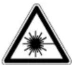
Attention: Laser beam Do not stare into beam Laser class 2
Protect yourself and your environment from accidents using suitable precautionary measures!
- Do not look directly into the laser beam with unprotected eyes.
- Never look into the path of the beam.
- Never point the laser beam towards reflecting surfaces and persons or animals. Even a laser beam with a low output can cause damage to the eyes.
- Caution - methods other than those specified here can result in dangerous radiation exposure.
- Never open the laser module. Unexpected exposure to the beam can occur.
- If the device is not used for an extended period of time, the batteries should be removed.
- The laser may not be replaced with a different type of laser.
- Repairs of the laser may only be carried out by the laser manufacturer or an authorised representative.
Safety instructions for handling batteries
- Always make sure that the batteries are inserted with the correct polarity (+ and -), as indicated on the battery.
- Do not short-circuit batteries.
- Do not charge non-rechargeable batteries.
-
Do not overcharge batteries!
-
Do not mix old and new batteries or batteries of different types or manufacturers! Replace an entire set of batteries at the same time.
-
Immediately remove used batteries from the device and dispose of them properly! Do not throw batteries away with household waste. Defective or used batteries must be recycled according to Directive 2006/66/EC. Return batteries and / or the device to the collection facilities offered. Contact your local authority or city administration for information about disposal options.
-
Do not allow batteries to heat up!
- Do not weld or solder directly on batteries!
-
Do not dismantle batteries!
-
Do not allow batteries to deform!
- Do not throw batteries into fire!
- Keep batteries out of the reach of children.
- Do not allow children to replace batteries without supervision!
- Do not keep batteries near fire, ovens or other sources of heat. Do not use batteries in direct sunlight or store them in vehicles in hot weather.
- Keep unused batteries in the original packaging and keep them away from metal objects. Do not mix unpacked batteries or toss them together! This can lead to a short-circuit of the battery and thus damage, burns or even the risk of fire.
- Remove batteries from the equipment when it will not be used for an extended period of time, unless it is for emergencies!
- NEVER handle batteries that have leaked without appropriate protection. If the leaked fluid comes into contact with your skin, the skin in this area should be rinsed off under running water immediately. Always prevent the fluid from coming into contact with the eyes and mouth. In the event of contact, please seek immediate medical attention.
- Clean the battery contacts and corresponding contacts in the device prior to inserting the batteries.
Residual risks
The electric tool has been built according to state-of-the-art and the recognised technical safety rules. However, individual residual risks can arise during operation.
- Health hazard due to electrical power, with the use of improper electrical connection cables.
-
Furthermore, despite all precautions having been met, some non-obvious residual risks may still remain.
-
Residual risks can be minimised if the "Safety instructions" and "Proper use" are observed along with the whole of the operating instructions.
- Do not load the machine unnecessarily: excessive pressure when sawing will quickly damage the saw blade, which results in reduced output of the machine in the processing and in cut precision.
- When cutting plastic material, please always use clamps: the parts which should be cut must always be fixed between the clamps.
- Avoid accidental starting of the machine: the start button may not be pressed when inserting the plug in an outlet.
- Use the tool that is recommended in this manual. This is how to ensure that your machine provides optimum performance.
- Keep your hands away from the work area, when the machine is in operation.
- Before performing setting or maintenance work, release the start button and pull out the power plug.
Warning!
This power tool generates an electromagnetic field during operation. This field can impair active or passive medical implants under certain conditions. In order to prevent the risk of serious or deadly injuries, we recommend that persons with medical implants consult with their physician and the manufacturer of the medical implant prior to operating the power tool.
7. Technical data
AC motor. 220-240V~50Hz
Nominal power S1 1200 W
Operating mode.. 5625% 1500 W
Idle speed 0 5000 rpm
Carbide saw blade 210x030x2.6mm
Number of teeth 48
Maximum tooth width of the saw blade. 3 mm
Pivot range -45°/0°/+45°
Mitre cut. 0° to 45° to the left
Saw width at 90° 120x60mm
Saw width at 45° 80x60mm
Saw width at 2 × 45° (double litre cut) ... 80 × 35 mm
Protection class .II/
Weight approx. 7.6 kg
Laser class 2
Laser wavelength. 650 nm
Power of laser. .< 1 mW
- Operating mode S6, uninterrupted, periodic operation. The mode comprises of a start-up period, a time with constant load and an idle time. The operating time is 10 mins, the duty cycle is 25% of the operating time.
The workpiece must have a minimum height of 3mm and a minimum width of 10mm .
Make sure that the workpiece is always secured with the clamping device.
Noise
The noise values have been determined in accordance with EN 62841.
Sound pressure level L 99.6 dB
Uncertainty K 3 dB
Sound power level LWA 1126 dB
Wear hearing protection.
Excessive noise can result in a loss of hearing.
The specified noise emission values have been measured in accordance with a standardised test procedure and can be used to compare one power tool with another.
The specified noise emission values can also be used for an initial estimation of the exposure.
Warning:
- The noise emission values can vary from the specified values during the actual use of the power tool, depending on the type and the manner in which the power tool is used, and in particular the type of workpiece being processed.
- Try to keep the stress as low as possible. For example: Limit working time. In doing so, all parts of the operating cycle must be taken into account (such as times in which the electric tool is switched off or times in which it is switched on, but is not running under a load).
8. Before commissioning
- Open the packaging and carefully remove the device.
- Remove the packaging material, as well as the packaging and transport safety devices (if present).
- Check whether the scope of delivery is complete.
- Check the device and accessory parts for transport damage.
- If possible, keep the packaging until the expiry of the warranty period.
ATTENTION
The device and the packaging are not children's toys! Do not let children play with plastic bags, films or small parts! There is a danger of choking or suffocating!
Always ensure that the machine is stable and secured, e.g. by fixing it to a workbench.
- The machine must be securely installed. Secure the machine through the holes on the fixed saw table (9) with 4 screws (not included in the scope of delivery) to a workbench, machine stand or similar.
- Prior to commissioning, all covers and safety devices must be mounted correctly.
- It must be possible for the saw blade to run freely.
- In case of previously machined wood, be aware of any foreign objects, such as nails or screws, etc.
- Before you press the ON/OFF switch (1) check that the saw blade is fitted correctly. Moving parts must run smoothly.
- Before connecting the machine, make certain that the data on the type plate matches with the mains power data.
8.1 Assembling the work piece clamping device (fig. 2)
- Loosen the locking screw (19) and attach the work piece clamping device (15) to the left or right of the fixed saw bench.
- Afterwards, retighten the locking screw (19).
8.2 Assembling the work piece supports (fig. 2-3)
- Loosen the locking screw (14) and guide the workpiece support (18) through the hole provided on the side of the fixed saw table.
- Make sure that the workpiece support (18) is also guided through the two plates on the underside.
- Afterwards, retighten the locking screw (14).
- Repeat this process on the other side.
8.3 Assembling the support stand (fig. 2-3)
- Loosen the locking screw (20) on the underneath of the saw and guide the stand bracket (21) through the specified holes on the back of the saw.
- Afterwards, retighten the locking screw (20).
8.4 Sawdust bag (fig. 4)
The saw is equipped with a dust bag (17) for chips.
- Squeeze together the metal ring on the dust bag and attach it to the outlet opening in the motor area.
- The dust bag (17) can be emptied via the zip on the underside.
Connection to an external dust extraction system
- Connect the suction hose to the dust extraction.
- The dust extraction system must be suitable for the material to be processed.
- Use a special extraction device to extract dusts that are particularly harmful to health or carcinogenic.
8.5 Checking the movable saw blade guard safety device (5)
The saw blade guard protects against accidental contact with the saw blade and against flying chips.
Check function.
To do this, fold the saw down:
- The saw blade guard (5) must expose the saw blade when it is swung down without touching other parts.
- When the saw is folded up to the initial position, the saw blade guard must automatically cover the saw blade.
9. Attachment and operation
9.1 Setting up the litre saw (fig.1 - 3)
- Retighten the set screw (7) in order to secure the rotary table (13).
- Use the handle (3) to adjust the rotary table (13) to the desired angle.
NOTE
The litre saw can be pivoted left and right with the rotary table (13). Exact angle adjustment (11) is possible on the basis of the scale. The angle can be precisely and quickly adjusted from 0° to 45° with locking positions at 15° , 22.5° and 30° .
- Retighten the locking screw (7) to lock the rotary table (13) in position.
- The saw is unlocked from the lower position by gently pressing down on the machine head (4) and, at the same time, pulling out the locking pin (25) from the engine mount.
-
Swivel the machine head (4) upwards.
-
It is possible to secure the clamping device (15) to the left or right on the stationary saw table (9). Insert the clamping device (15) in the hole on the rear side of the stop rail (8) and secure it with the star grip screw (19).
- The machine head (4) can be tilted to the left to max. 45° by loosening the locking screw (23).
- Workpiece supports (18) must always be secured and used during work.
9.2 Precision adjustment of the stop for crosscut at 90° (fig. 5)
Tool required:
- Allen key 3 mm (D)
Stop bracket not included in the scope of delivery.
- Lower the machine head (4) and fix it with the locking pin (25).
- Loosen the locking screw (23).
- Place 90° stop bracket (A) between saw blade (6) and rotary table (13).
- Loosen the locknut (26a).
- Adjust the adjustment screw (26) until the angle between the saw blade (6) and the rotary table (13) is 90° .
- Re-tighten the locknut (26a).
9.3 Crosscut 90° and rotary table 0° (Fig. 1/2/3/6) Attention! To make 90° crosscuts, the adjustable stop rail (8a) must be fixed at the inner position.
Tool required:
-
Allen key 3 mm (D)
-
Open the set screw (8b) for the adjustable stop rail (8a) and push the adjustable stop rail (8a) inwards.
- The adjustable stop rail (8a) must be fixed far enough in front of the innermost position that the distance between the adjustable stop rail (8a) and the saw blade (6) amounts to a maximum of 8mm .
- Before making the cut, check that no collision could occur between the stop rail (8a) and the saw blade (6).
- Tighten the locking screw (8b) again.
- Move the machine head (4) to the upper position.
-
Place the wood to be cut against the stop rail (8) and on the rotary table (13).
-
Secure the material on the fixed saw table (9) with the clamping devices (15) to prevent it from shifting during the cutting process.
See section 09.12. - Unlock the locking switch (2) and press the on/off switch (1) to switch the motor on.
- Move the machine head (4) with the handle (3) evenly and with light pressure downwards until the saw blade (6) has cut through the workpiece.
- When the sawing process is finished, return the machine head to the upper resting position and release the ON/OFF switch (1).
Attention!
The return spring automatically raises the machine. Do not let go of the handle (3) after finishing cutting but move the machine head slowly upwards with light counter-pressure.
9.4 Crosscut at 90° and rotary table between 0° and 45° (fig. 1/2/3/6)
The mitre saw can be used for angled cuts of 0° - 45° to the left and right.
Attention!
To make 90° crosscuts, the adjustable stop rail (8a) must be fixed at the inner position.
Tool required:
-
Allen key 3mm (D)
-
Open the set screw (8b) for the adjustable stop rail (8a) and push the adjustable stop rail (8a) inwards.
- The adjustable stop rail (8a) must be fixed far enough in front of the innermost position that the distance between the adjustable stop rail (8a) and the saw blade (6) amounts to a maximum of 8mm .
- Before making the cut, check that no collision could occur between the stop rail (8a) and the saw blade (6).
- Secure the set screw (8b) again.
- Retighten the set screw (7) in order to secure the rotary table (13).
- Using the handle (3), set the rotary table (13) to the desired angle.
- Retighten the locking screw (7) to lock the rotary table (13) in position.
Make a cut as described under section 9.3.
9.5 Precision adjustment of the stop for litre cut at 45° (fig. 1/2/3/6/7/8)
Tool required:
- Allen key 3 mm (D)
Stop bracket not included in the scope of delivery.
- Lower the machine head (4) and fix it with the locking pin (25).
Fix the rotary table (13) in the 0° position. - Attention! For metre cuts (inclined saw head), the adjustable stop rail (8a) must be fixed in the outer position.
- Loosen the locking screw (8b) on the moveable stop rails (8a) and push the moveable stop rails (8a) outwards.
- The adjustable stop rail (8a) must be fixed far enough in front of the innermost position that the distance between the adjustable stop rail (8a) and the saw blade (6) amounts to a maximum of 8mm .
Before making the cut, check that no collision could occur between the stop rail (8a) and the saw blade (6). - Tighten the locking screw (8b) again.
- Loosen the locking screw (23) and tilt the machine head (4) to the left, to 45° , using the handle (3).
- Place 45° stop bracket (B) between saw blade (6) and rotary table (13).
- Loosen the locknut (22a) and the adjustment screw (22) until the angle between the saw blade (6) and the rotary table (13) is exactly 45° .
- Re-tighten the locknut (22a).
- Then check the position of the angle display. If necessary, loosen the pointer (28) with a Phillips screwdriver, set the scale (27) to 45° position and re-tighten the retaining screw.
9.6 Mitre cut between 0° and 45° and rotary table between 0° (fig. 1/2/3/6)
The litre saw can be used for litre cuts of 0° - 45° to the left of the work surface.
Attention!
For litre cuts (inclined saw head), the moveable stop rail (8a) must be fixed in the outer position.
Attention!
For litre cuts between 0° and 45° , mount the clamping device (workpiece clamp) (15) only on the right side.
Tool required:
-
Allen key 3 mm (D)
-
Loosen the locking screw (8b) on the moveable stop rails (8a) and push the moveable stop rails (8a) outwards.
- The adjustable stop rail (8a) must be fixed far enough in front of the innermost position that the distance between the adjustable stop rail (8a) and the saw blade (6) amounts to a maximum of 8 mm.
Before making the cut, check that no collision could occur between the stop rail (8a) and the saw blade (6). - Secure the set screw (8b) again.
- Move the machine head (4) to the upper position.
Fix the rotary table (13) in the 0° position. - Loosen the locking screw (23) and tilt the machine head (4) to the left with the handle (3) until the pointer (28) points to the desired angle on the scale (27).
- Retighten the locking screw (23).
Make a cut as described in point 9.3.
9.7 Mitre cut between 0° and 45° and rotary table between 0° and 45° (fig. 1/2/3/6)
Tool required:
- Allen key 3 mm (D)
The litre saw can be used to make litre cuts to the left of 0° - 45° in relation to the work face and, at the same time, 0° - 45° to the left or 0° - 45° to the right in relation to the stop rail (double litre cut).
Attention!
For litre cuts (inclined saw head), the adjustable stop rail (8a) must be fixed in the outer position.
With a cross-cut saw tilted to 31.6° and a unit tilt of 33.9° , isosceles triangular strips and profiles such as stucco edge profiles can be mitred with the profile side down.
This is particularly advantageous for large profiles that exceed the maximum cutting height with normal insertion.
It also makes it easy to solve problems with the angle at the corners, which is often not right-angled.
Attention!
For litre cuts between 0° and 45° , mount the clamping device (workpiece clamp) (15) only on the right side.
-
Loosen the locking screw (8b) on the moveable stop rails (8a) and push the moveable stop rails (8a) outwards.
-
The adjustable stop rail (8a) must be fixed far enough in front of the innermost position that the distance between the adjustable stop rail (8a) and the saw blade (6) amounts to a maximum of 8mm .
- Before making the cut, check that no collision could occur between the stop rail (8a) and the saw blade (6).
- Secure the set screw (8b) again.
- Move the machine head (4) to the upper position.
- Retighten the set screw (7) in order to secure the rotary table (13).
- Using the handle (3), set the rotary table (13) to the desired angle.
- Retighten the locking screw (7) to lock the rotary table (13) in position.
- Loosen the locking screw (23).
- Use the handle (3) to tilt the machine head (4) to the left to the desired angle (see also point 9.6).
- Retighten the locking screw (23).
Make a cut as described under section 9.3.
9.8 Changing the saw blade (fig. 1/2/3/9/10)
Pull out the mains plug!
Attention!
Wear protective gloves when changing the saw blade! Risk of injury!
- Swing the machine head (4) upwards and secure with the locking bolt (25).
- Fold the saw blade guard (5) up sufficiently that the saw blade guard (5) is above the flange screw (29).
- With one hand, fit the Allen key (C) to the flange screw (29).
- Hold the Allen key (C) and slowly close the saw blade guard (5) until it touches the Allen key (C).
- Firmly press the saw shaft lock (32), and slowly turn the flange screw (29) clockwise. After max. one turn, the saw shaft lock (32) engages.
- Then undo the flange screw (29), by applying a slightly greater force in a clockwise direction.
- Fully unscrew the flange screw (29) and remove the outer flange (30).
- Take the blade (6) off the inner flange and pull out downwards.
- Carefully clean the flange screw (29), outer flange (30) and inner flange.
- Insert the new saw blade (6) in the reverse sequence and tighten.
-
Attention! The cutting angle of the teeth, i.e. the direction of rotation of the saw blade (6), must correspond to the direction of the arrow on the housing.
-
Before continuing work, check that the safety devices are functioning properly.
- Attention! After each saw blade change, check that the saw blade (6) runs freely in the table cut-out (10) in vertical position as well as when tilted to 45° .
Attention!
Changing and aligning the saw blade (6) must be carried out properly.
9.9 Replacing laser batteries (fig. 11)
- Remove the laser battery cover (34). Remove the 2 batteries.
- Replace both batteries with the same or an equivalent type. Make sure that they are inserted with the same polarity as the used batteries.
- Close the battery cover.
9.10 Switching on/off on the laser (fig. 11)
Switching on:
Move the ON/OFF switch (33) of the laser to the "1" position. A laser line is projected onto the material you wish to process, providing an exact guide for the cut.
Switching off:
Move the ON/OFF switch of the laser to the "0" position.
9.11 Adjusting the laser (fig. 12)
If the laser (35) is no longer showing the correct cutting line, it can be readjusted. To do so, open the screws (36) and set the laser by moving sideways to that the laser beam strikes the teeth of the saw blade (6).
9.12 Using the clamping handle (fig. 1/2)
The height of the clamping device (15) can be adjusted via the set screw (16).
- Lower the clamping device (15) onto the workpiece.
- Tighten the set screw (16) firmly.
- Turn the clamping handle (24) clockwise to clamp the workpiece.
To release the workpiece, proceed in reverse order.
10. Transport (fig. 13)
- Tighten the locking screw (7) to lock the rotary table (13).
-
Push the machine head (4) downwards and lock it with the locking pin (25). The saw is now locked in the lower position.
-
Carry the machine by the transport handle (37).
- To reassemble the machine, proceed as described in chapter 8-9.
11. Maintenance
Warning!
Pull out the mains plug before carrying out any adjustments, maintenance or repair work!
General maintenance tasks
Wipe swarf and dust off the machine from time to time with a cloth. Oil the rotating parts once monthly to extend the life of the tool. Do not oil the motor.
Do not use corrosive agents for cleaning the plastic.
Cleaning the movable saw blade guard safety device (5) (fig. 16)
Check the saw blade guard for dirt before each start-up.
Remove old shavings and wood splinters using a brush or similar suitable tool.
Make sure that the guide bracket (31) moves smoothly.
Replacing the table insert (10) (fig. 14)
Danger!
With a damaged table insert (10) there is a risk of small parts getting stuck between table insert and saw blade, blocking the saw blade.
Immediately replace damaged table inserts (10)!
- Unscrew the screws (E) from the table insert (10).
- Remove the table insert (10).
- Install new table insert (10).
- Tighten the table insert screws (E).
Brush inspection (fig. 15)
If the machine is new, check the carbon brushes after the first 50 operating hours or if a new brush has been mounted. After the initial check, check every 10 operating hours.
If the carbon is worn down to a length of 6mm or the spring or the shunt wire is burnt or damaged, both brushes must be replaced. If the brushes are found to be usable after removal, they can be reinstalled.
To service the carbon brushes, open both locks (as shown in figure 15) counterclockwise. Then remove the carbon brushes.
Re-insert the carbon brushes in reverse order.
Service information
With this product, it is necessary to note that the following parts are subject to natural or usage-related wear, or that the following parts are required as consumables.
Wearing parts*: carbon brushes, saw blade, table inserts, saw dust bags
- may not be included in the scope of supply!
12. Storage
Store the device and its accessories in a dark, dry and frost-free place that is inaccessible to children. The optimum storage temperature lies between 5 and 30°C .
Store the power tool in its original packaging.
Cover the electric tool to protect it from dust or moisture.
Store the operating manual with the power tool.
13. Electrical connection
The electrical motor installed is connected and ready for operation. The connection complies with the applicable VDE and DIN provisions. The customer's mains connection as well as the extension cable used must also comply with these regulations.
Important information
In the event of overloading, the motor will switch itself off. After a cool-down period (time varies) the motor can be switched back on again.
Damaged electrical connection cable
The insulation on electrical connection cables is often damaged.
This may have the following causes:
- Pressure points, where connection cables are passed through windows or doors.
- Kinks where the connection cable has been improperly fastened or routed.
- Places where the connection cables have been cut due to being driven over.
Insulation damage due to being ripped out of the wall outlet. - Cracks due to the insulation ageing.
Such damaged electrical connection cables must not be used and are life-threatening due to the insulation damage.
Check the electrical connection cables for damage regularly. Ensure that the connection cables are disconnected from electrical power when checking for damage.
Electrical connection cables must comply with the applicable VDE and DIN provisions. Only use connection cables with the designation "H05VV-F".
The printing of the type designation on the connection cable is mandatory.
Safety information for replacing damaged or defective mains connection cables
Type X:
If the mains connection cable of this device is damaged, it must be replaced by a special connection cable which can be obtained from the manufacturer or its service department.
AC motor:
The mains voltage must be 220 - 240V
- Extension cables up to 25m long must have a cross-section of 1.5 square millimetres.
- Connections and repair work on the electrical equipment may only be carried out by electricians.
Please provide the following information in the event of any enquiries:
Type of current for the motor
Data of motor type plate
14. Disposal and recycling
Information on packaging


The packaging materials are recyclable. Please dispose of packaging in an environmentally friendly manner.
Information on the German Electrical and Electronic Equipment Act (ElectroG)
Electrical and electronic appliances do not belong in household waste, but should be collected and disposed of separately.
- Used batteries or rechargeable batteries that are not installed permanently in the old appliance must be removed non-destructively before disposal. Their disposal is regulated by the battery law.
- Owners or users of electrical and electronic appliances are obliged by law to return them after use.
-
The end user bears personal responsibility for deleting his personal data from the old appliance to be disposed of.
-
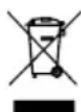
The symbol of the crossed-through rubbish bin means that electrical and electronic appliances may not be disposed of in the household rubbish.
-
Electrical and electronic appliances can be handed in at the following places at no charge:
-
Public service disposal or collection points (e.g. municipal building yards)
- LIDL offers you return options directly in the branches and stores. Return and disposal are free of charge for you.
-
Up to three waste electrical devices per type of device, with an edge length of no more than 25 centimetres, can be returned free of charge to the manufacturer without prior purchase of a new device from the manufacturer or taken to another authorised collection point in your vicinity.
Further supplementary take-back conditions of the manufacturers and distributors can be obtained from the respective customer service. -
If the manufacturer delivers a new electrical appliance to a private household, the manufacturer can arrange for the free collection of the old electrical appliance upon request from the end user. Please contact the manufacturer's customer service for this.
- These statements only apply to appliances that are installed and sold in the countries of the European Union and are subject to European Directive 2012/19/EU. Different provisions may apply to the disposal of electrical and electronic appliances in countries outside the European Union.
Information on the German Battery Act (BattG)

Used batteries and rechargeable batteries do not belong in household waste, but should be collected and disposed of separately.
- For safe removal of batteries or rechargeable batteries from the electrical appliance and for information on their type or chemical system,
- follow the further information within the operating or installation instructions.
-
Owners or users of batteries and rechargeable batteries are obliged by law to return them after use. Return is limited to the handover of customary household quantities.
-
Used batteries can contain harmful substances or heavy metals that can cause damage to the environment and human health. Reuse of the used batteries and use of the resources contained therein contributes to the protection of these two essential commodities.
- The symbol of the crossed-through rubbish bin means that batteries and rechargeable batteries may not be disposed of in household rubbish.
- In addition, if the symbol Hg, Cd or Pb appears under the rubbish bin, this stands for the following:
Hg: Battery contains more than 0.0005% mercury
- Cd: Battery contains more than 0.002% cadmium
- Pb: Battery contains more than 0.004 % lead
-
Rechargeable batteries and batteries can be handed in at the following places at no charge:
-
Public service disposal or collection points (e.g. municipal building yards)
- Points of sale of batteries and rechargeable batteries
- Disposal points of the common take-back system for the used batteries of appliances
-
Disposal point of the manufacturer (if not a member of the common take-back system)
-
These statements apply only to rechargeable batteries and batteries that are sold in the countries of the European Union and that are subject to European Directive 2006/66/EU. Different provisions can apply to the disposal of rechargeable batteries and batteries in countries outside the European Union.
15. Troubleshooting
| Fault Possible cause Remedy | ||
| Motor does not work | Engine, cable or connector defective, mains fuses blown. | Arrange for inspection of the machine by a specialist. Never repair the motor yourself. Danger! Check mains fuses and replace as necessary |
| The engine runs slowly and does not reach the operating speed. | Voltage too low, coils damaged, capacitor burnt. | Contact the utility provider to check the voltage. Arrange for inspection of the motor by a specialist. Arrange for replacement of the capacitor by a specialist. |
| Engine producing excessive noise. | Coils damaged, motor defective. Arrange for | inspection of the motor by a specialist. |
| The motor does not reach its full power. | Circuits in the network are overloaded (lamps, other motors, etc.). | Do not use any other equipment or engines on the same circuit. |
| Motor overheats easily. | Overloading of the motor, insufficient cooling of the motor. | Avoid overloading the motor while cutting, remove dust from the motor in order to ensure optimal cooling of the motor. |
| Saw cut is rough or wavy. | Saw blade dull, tooth shape not appropriate for the material thickness. | Resharpen saw blade and/or use suitable saw blade. |
| Workpiece pulls away and/or splinters. | Excessive cutting pressure and/or saw blade not suitable for use. | Insert suitable saw blade. |
16. Warranty certificate
Dear Customer,
All of our products undergo strict quality checks to ensure that they reach you in perfect condition. In the unlikely event that your device develops a fault, please contact our service department at the address shown on this guarantee card. Of course, if you would prefer to call us then we are also happy to offer our assistance under the service number printed below. Please note the following terms under which guarantee claims can be made:
These guarantee terms cover additional guarantee rights and do not affect your statutory warranty rights. We do not charge you for this guarantee.
- Our guarantee only covers problems caused by material or manufacturing defects, and it is restricted to the rectification of these defects or replacement of the device. Please note that our devices have not been designed for use in commercial, trade or industrial applications. Consequently, the guarantee is invalidated if the equipment is used in commercial, trade or industrial applications or for other equivalent activities. The following are also excluded from our guarantee: compensation for transport damage, damage caused by failure to comply with the installation/assembly instructions or damage caused by unprofessional installation, failure to comply with the operating instructions (e.g. connection to the wrong mains voltage or current type), misuse or inappropriate use (such as overloading of the device or use of non-approved tools or accessories), failure to comply with the maintenance and safety regulations, ingress of foreign bodies into the device (e.g. sand, stones or dust), effects of force or external influences (e.g. damage caused by the device being dropped) and normal wear resulting from proper operation of the device.
The guarantee is rendered null and void if any attempt is made to tamper with the device.
- The guarantee is valid for a period of 3 years starting from the purchase date of the device. Guarantee claims should be submitted before the end of the guarantee period within two weeks of the defect being noticed. No guarantee claims will be accepted after the end of the guarantee period. The original guarantee period remains applicable to the device even if repairs are carried out or parts are replaced. In such cases, the work performed or parts fitted will not result in an extension of the guarantee period, and no new guarantee will become active for the work performed or parts fitted. This also applies when an on-site service is used.
In order to assert your guarantee claim, please contact the service partner shown below. If the complaint is within the guarantee period, we will provide you with a return slip, with which you can return your defective device free of charge to us. It would help us if you could describe the nature of the problem in as much detail as possible. If the defect is covered by our guarantee then your device will either be repaired immediately and returned to you, or we will send you a new device.
Of course, we are also happy offer a chargeable repair service for any defects which are not covered by the scope of this guarantee or for units which are no longer covered. To take advantage of this service, please send the device to our service address.
Service-Hotline (GB): Service-Hotline (IE): Service-Hotline (NI)
008004003400300800400340030080040034003
(0,00 EUR/Min.) (0,00 EUR/Min.) (0,00 EUR/Min.)
Service-Email (GB): Service-Email (IE): Service-Email (NI):
service.GB@scheppach.com
service.IE@scheppach.com
service.NI@scheppach.com
Service Address (GB): Service Address (IE): Service Address (NI):
Forest Park & Garden
Coed Court, Taffsmead Road
Treforest, Ind. Estate, Pontypridd CF375SW
LetMeRepair
1 Langlands Court / Kelvin South Business Park
East Kilbride G75 OYB
Forest Park & Garden
Coed Count, Taffsmead Road
Treforest, Ind. Estate, Pontypridd CF375SW
service.IT@scheppach.com
At www.lidl-service.com you can download this and many more manuals, product videos plus installation software.
The QR code takes you directly to the Lidl service page (www.lidl-service.com) and you can open your operating manual by entering the article number (IAN) 499235_2204.
Günzburger Straße 69
D-89335 Ichenhausen
Verehrter Kunde,
service.AT@scheppach.com
Service-Adresse (DE):
Scheppach GmbH
Günzburger Str. 69
Nosyou'recommendands:
Service-hotline (BE):
0080040034003
[0, 00 / Min]
Service-Hotline (CH):
0080040034003
[0, 00 Min]
Email du service (FR):
service.FR@scheppach.com
E-mailadres (BE):
service.BE@scheppach.com
Service-Email (CH):
service.CH@scheppach.com
Scheppach France Strassburg
2, Impasse Jean Millot
FR-6700 Strasbourg
Serviceadres (BE):
Service Center Bruyninckx
Guldendelle 30
BE-1930 Zventem (Nossegem)
Günzburger Straße 69
D-89335 lichenhausen
Geachte klant,
10. Transport (afb. 13)
Service-hotline (BE):
0080040034003
(0,00 €/Min.)
E-mailadres / Email du service (NL):
service.NL@scheppach.com
E-mailadres (BE):
service.BE@scheppach.com
Serviceadres / Adresse du service (NL):
Günzburger Straße 69
D-89335 lichenhausen
Vázény zákazniku,
Günzburger Straße 69
D-89335 Ichenhausen
Szanowny Kliencie,
Günzburger Straße 69
D-89335 lichenhausen
Vázény zákaznik,
Zelame Vam vela zabavy a uspechov pri praci s Vaśim novym pristrojom.
Upozornenie:
Günzburger Straße 69
Günzburger Straße 69
D-89335 Ichenhausen
Karekunde,
8.2 Montering of emnesupporter (fig. 2-3)
service.IT@scheppach.com
Günzburger Straße 69
D-89335 lichenhausen
Spostovani kupec,
zelimo vam veliko veselja in uspeha pri delu z va so novo napravo.
Napotek:
Günzburger Straße 69
D-89335 Ichenhausen
Postovani kupci,
Zelimo vam mnogo zadovoljstva i uspieha pri radu s novim uredajem.
Napomena:
Prema vazećem njemačkom Zakun o odgovornosti za proizvode, proizvodac ovog uredaja ne odgovara za šteke koje nastanu na ovom uredaju ili koje ovaj uredaj uzrokuje u slucaju:
- nestrucnim rukovanjem
- nepridržavanja priručnika za uporabu,
- popravcima koje obave neovlasteni strucnjaci
- montažom i zamjenom neoriginalnih rezervnih dijelova
- nenamijske uporabe,
- kvarova elektricnog sustava zbog nepridržavanja propisa i odredaba o elektricnoj energiji VDE 0100, DIN 57113 / VDE0113.
OPREZ
service.HR@scheppach.com
Usluga-Adresa (HR):
Microtec systemi d.o.o
llirska 33
HR - 10000 Zagreb / Croatia

Na stranici www.lidl-service.com mozte preuzeti ovaj mnogo drugih priurcnika, filmova o proizvodima i instalacjski softver.
S pomocu QR koda izravno prelazite na stranicu Lidl Service (www.lidl-service.com) i unosjenjem broja articla (IAN) 499235_2204 mozete otvoriti svoj priručnik za uporabu.
Cuprins:
Instrument necessities:
- Cheie Inbus 3 mm (D)
Instrument necessities:
Instrument necessities:
Instrument necessities:
- Cheie Inbus 3 mm (D)
Instrument necessities:
Instrument necessities:
- Cheie Inbus 3 mm (D)
Stimata clienta, stimate client,
Hotline serviciu (RO):
0080040034003
(0,00 EUR/Min.)
Serviciu de e-mail (RO):
service.RO@scheppach.com
Adresa serviciu (RO):
Machine House S.R.L.
6. Yka3aHna 3a 6e3oNaCHOCT
06uyn yka3aHna 3a 6e3oNaChoc 3a eneKtpnueckn HNCTpyMeHTN
PNEUYPEXKDEHNE! PpOeTeTE BcNkUyKa3a-Hn 3a 6e3oNaChoc, HNCTpyKuH, NIOCTpaHn INTexHnueckn DAHN, PpeOCTabeHc C To3n EneKtpn-ueckn INCTpymEn. Iponyckn npn cna3BaHeTo Ha yKa3a-Hnra 3a 6e3oNaChoc n INCTpyKuHte MoT a DoBEdat Do TOKOB yIap, noKap n/Inn TeKKn HapaHBAHH.
3ana3e Bcunyka3aHna 3a6e3onacnoT n HCTpykun 3a 6bdeu npabkn.
N3no3BaHOTo B yka3aHnTa 3a 6e3oNaChOCT NOHrTne "eneKtpnueckn INHcTpymeHT" ce OTHacrdo 3axpaHbAHn OTMpexkata eIeKtpnueckn INHcTpymeHTn (C MPexko IPOBODNK) nIN Do 3axpaHbAHn C acyMylatop eneKtpnueeckn INHcTpymeHTn (6e3 MPexko IPOBOHDNK).
1. Besonachocht ha pa6othoto macto
2. Bezonaachoct npu pa6ota c eneKtpueckn TOK
a) IopdIbpxKaIte pa60THO cM MaCTo qHCTo N do6pe oCBeteHO. Be3npaIbKbT nHn HeOCBeteHNTE pa60THM MeTa MoT a Da IOBeDat Do 3NoNpyKN.
b) He pa6oTeTe c eIeKtpuueckn HNCTpyment BvB B3PNUBOONACHa Cpea, B KOrTo NMa 3aPAnMM TeUHOCTn, RaOBe Nm npaxObe. EneKtpuuecknte INHCTpymEtH Cb3dABat NcKpn, KOnTO MoTAt Da Bb3PiMaMeHrt Ppaxa Nm Napite.
c)ДрькTe Decaиpyrnnnua daeneu no BpeMe Ha n3non3baHeto Ha enektpnuecknru HnctpyMeHT.Прп рa3ceиBaHe moKTe DA n3ry6nTe KOHTpOIN Bbpxy enektpnuecknru INCTpyMeHT.
a) Μεπεπβτ Ha eηκtpnueckn ένικtpymeHT Tp6Ba Da otroBapr Ha KOtakTa. Μεπεπβr He 6nBa Da ce προMeH No HNKakbB HauHH. He n3no3BaIte aanTepn ΜεπεΠ ΚaedHo CbC 3a3eMeH eηκtpnueckn ένικtpymeHTN. He npomeH e ΜεπεΠ ΑODXODAùn KOtAKTH HAMANBA t pɪsKa OT TOKOB yɪap.
b) IV36aBaTe TeleceH KOHTAK CbC 3a3eMeHn NOBbpxHOCTN KATO Tpb6n, OTONINTENH ypeu, cyphHn XnaADHHnCu. CbIeCTbByBa NOBNIeH pNCKOTOKOB yDap, Korato TaIOTO Bn e 3a3eMeHo.
c) Pn3eEneKtpnuecknte HNCTpymEnT OdbxN n Bnara. IpoHnKBaHTo Ha BOda B eNEKtpnueckn HNCTpymENT yBENuaba pncKa OT TOKOB yOp.
d) He n3noI3baIte cBeHNHTENHn npOBoHNK He no npEpaHa3NaueHne, 3a HocHe nn 3aKa- qane Ha eneKtpuueckn HnctpyMeHn 3a N3dbpNAbe Ha quencena ot KOnTaKa. NaTe cBeHNHTENHn npOBoHNK OT RopeunHa, MacNo, octpn Pb6Obe nn DnXKeu Ce qactn. IobpeHn nn ycyKaHn cBeHNHTENH npOBoHNzu yBEnuBaT PnCKa OT TKOB ynap.
e) Korato pa6oHTte c enektpnueckn HNCTpyment Ha otKpHTo, n3non3BaIte camo ydbnxTeHNn NHHN, KOHTO cbso ca noxDxOaun 3a ynotpe-6a Ha otKpHTo. IV3non3BAHeTO Ha noDxOaHa 3a ynoTpe6a Ha otKpHTo ynbNxTeHa NNHn HAmAJBa PNCKa OT TOKOB yap.
f) Korato ynotpe6ata Ha eNeKtpnueckna HNCTpymeHT BbB BnaxHa cpea He MoXe da 6bdeH36erHata, H3no3BaTe DeΦeKTHOTOKOBA 3a-nta. N3no3BaHTo Ha DeΦeKTHOTOKOBA 3aunTa HA-MaJIraBa pIcKa OT TOKOB yap.
3. Besonachoct ha xopata
a)БbTe BHNMaTeHn,O6pTaIe BHNMaHne Ha TOBa, KoTo npabnte, n NOxoxJaIte pa3ymHO KbM pa6oTata c eNEKtpueckn HcTpymENT. He n3NoJBAaIte eNEKtpueckn HcTpymENTn, aKO cTe yMopeHn Hn NOD BnHaHHeTo Ha HApKOTnU, ankoxon nn MeNkAmENTn. MoMeHT HeBHNMaHHe pN n3NoJ3BaHeto Ha eNEKtpueckn HcCTpymEHT MoKe Ia DoBeJe Io cepNo3Hn HapAraBaHna.
b) Hocete nuchn npedna3n cpeCTba n Bnhar npedna3n ouina. Hocehto ha nuih npedna3n cpeCTba, kato npotboopaxoba macka, npedna3n o6yBkn, konTo He ce xnb3raT, kacka nn aHTnoHn, cnopeBnida n ynotpe6ata Ha eNeKtpueckn HNCTpyMeHT, HamaIBA pnckA ot HapaHraBaHH.
c) N368BaIte HeBbONHO BkNIOUbaHe. YBepTe ce, ye enektpnuecknrt HNCTpymeHt e N3KIOUeyen npEn Da rO CBpXeTe KbM enektpo3aXpaHbA- heto n/nnn akymylatopa, npEn da rO B3eme Te nn HocHTe.Ako npHn HOceHTo Ha enektpnueeckn HNCTpymeHt DpbXeTe pbcTa cn BBpxy PpekbCbaa HnN CBpXeTe KbM enektpo3axpaHbAHeto BkNIOUeH enektpu- cheKN HNCTpymeHT, TOBa MoKe da DOBBeDo 3IOnOJyKn.
4. Ynotpe6a n 6opabeHe c eneKtpueckna nHCTpymEnT
d) Otctpahete IHctpymeHTte 3a Hactpoika nna raeeHnte KIOUObe, npedn da BkIOuHTe enektpueckna IHcTpymeH. IHctpymeH nnn KIOU,HAMnpaas Ce BBB Bbptraa ce qact Ha eNEKTPnuEckna IHcTpymeH, MOKe Da IOBeDe Do HapaHBaHHa.
e) 364baTe HnpabnHa cToKa Ha TaIto. Ocnypete cn cta6nJen cToex n noctoHno na3e paBHOBeCne. Taka moKeTe da KOHTponipate enektpueckn IHCtpyMeH n-oO6pe npn HeouaKaBaHn CHTyaUHN.
f) Hocete noxogno 06nekno. He hocete npokn dpexn nn nakntn. Dpbxte kocata n o6neknoto cn daney ot dbnxceu ce qactn. Wnpokn dpexn, nakntn nn nbnn Kocn MOrat da 6bdo3axbaHATN OT DBNXeUe CE qactn.
g) Korato Morat da 6bdat MOHTnpaHn npaxoN3cmykbaun n npaxoynaBau yctpoiCTBa, Te Tp8ba da ca cbbp3aHn da ce n3non3bat npabnHO. N3non3BaHeto Ha npaxoN3cmykbaao ycTPOIcTBO MoKe da HAMAN BpeINTe 3a 3dpABeTo nopaa nn npax.
h) He ce noadabaihe Ha faanuboto yvBCTBO 3a 6e0nacnoht Hne npene6perbaite npabnata 3a 6e0nacnoct npu pa6ota c enektpnueecknte Hnctpymehtn, dopn ako cneM HorokpatHata m ynotpe6a Mncnite ue nno3habate do6pe. He6pexhnte DeiCTbna MOat da IOBeDat Do TeKKn Te- neChn NobpeDn B pAMKNTe Ha qactn ot cekyHdata.
a) He npetobapbaite enektpueckn HNCTpyMeHT. Nsnonsbate noxodmaa 3a Baawata pa6ota enektpueckn HNCTpymeHT. C noxDoxoJaunie enektpueckn HNCTpymeHT pa6otnte no-do6pe n no-cnrypho B dnaana30Ha ha pa6OTHNTe My xapaKtepncTKn.
b) He n3non3BaIte enektpnueckn nHCTpymeHT, uHTo npekbcBau e nobpeH. EneKtpnueckn nH- cTpyMeHT, KOto He moKe da ce BKNIOUBA HIN N3KNIOUBA, e onaceH n Tpa6Ba da 6bJe peMOHTipan.
c) N3BaTe 8eCena ot KOHTAKTa n/nnn 3BaTe CMeHraemna Akymylatop, npedn da n3BbpuBATE HAcTpoKn No ypea, da CMeHare qactn Ha pa6oTHn HnCTpymeHt nn Da ocTabnte eNeKtpnueckn HnCTpymeHa HacTpaHn. Ta3n MApKa 3a 6e3onachocnt npedotBpTaRa HeymuJeHOTo BKNIOUOBAHe Ha INCTpyMeHa.
d) CbxpahraBte Hn3non3BaHnte enektpueckn HNCTpymEn Ha HeoctbnHO 3a deca Macto. He no3boJraBte enektpuecknTn HNCTpymENT da 6bde n3non3BaH ot Iuca, KOtO He ca 3a-nos3nat c Hero nn He ca npouen Te3n HNCTpykun. EneKtpuecknTe HNCTpymEn Ca onacn, aKO ce n3non3BAT OT HeONHTHn Iuca.
e) NpOaDbPxaIte enektpnuecknte HNCTpyMeHTn pa6oTHna HNCTpyMeHT rpnXlnBO. IpOBepaBaiTe daHn DnHexeunite ce qactn fynKunoHnpat 6zynpeuHO n He 3aJxDat, daHn Hma CuyneHn nn Taka NobpeHn qactn, ye da HopywaBt fynKuoHnpaHeto Ha enektpnueckn HNCTpyMeHT. NobpeHnte qactn cneBa da 6bDat pemOnTupAHn ppeuHn 3no3BaHeto Ha enektpnueckn HNCTpyMeHT. Mhoro 3noNoIyKn ca npUnHeHn OT NooNoDbPxAHN enektpnueckn HNCTpyMeHTn.
f) PnDpKaIte pexeHnte HNCTpyMeHTn Hato-ueHN uHCTN. rPnKInBO nOaBpKaHnte peXeUHCTpyMeHTn c octpnpeXeU pboBe ce 3aklnHBAT NO-MALKO h Ce BOJAT No-NecHO.
g) N3noN3baIte enektpueeckn HNCTpymENT, npHnadLeXHoCTnTe, pa6oTHnte HNCTpyKcun. PnTOBa B3emaIte nOa BHMaHne ycNoBnTa Ha pa6ota n DeCTbHeTo, Koeto Tpa6Ba da ce n3BbpH. Ynotpe6ata Ha enektpueeckn HNCTpymENT 3a pa3nnHOn OT npedBnDeHIne npnIOxehn MoKe Ja DOBeJe Do OAnCHn CHTyaCmN.
h) PabeTe npbKnte n TexHnTe nobbpXHOCTn cyxu, uctn 6e3 macno n rpec. Xlb3raBnTe dpbKn N TexHnTe nobbpXHOCTn He no3BOJRaT 6e3ONaCha pa6ota N KOHTpOHa eNEkTpueckn HnCTpyMeHT B He- npedBnDEHN cHTyaun.
5. CepBn3
a) Bb3naraTe peMoHTn no Baun eneKtpueckn HNCTpymENT cAmo Ha KBanHmucnpAH nCneua-nctn n Camo C opunHANH peepBHN qactn. Taka ce rapantnpa, ye 6e3onachocTn ha eneKtpueckn HNCTpymENT ige ce 3ana3n.
YkaaHnra 3a 6e3oNaCHOCT 3a cIurkynapnte 3a p3aHe noD bbl
a) LInpkyIpaIte 3a pIaIe NoIbIbIc a npedHa3- HauEHN 3a pIaIe Ha IbpBO N IbPBeH npOdyKTH n He MoIat Da Ce I3NON3BAT 3a pIaIe Ha XKeIe3HN MATEpHann Kato npBTH, ZaHn, BnHTOBe n T.H. A6pa3INBHnT npax ige 6NoKnpa DnIXe- uHtTe ce YacTH Kato HanpHmep DoJIHn3aUHTEN KOJyX. UckPit e np PIAane I3rApT DoJIHn3aUHTEN KOJyX, BNOJKATA n DpyITHe INaCTMaCOBn YactN.
b) IIO B3MOXHOCT FHKnpaTe 06pa6OBaHnA detaiI cbc CTnCKa. Ipn FHKnpaHe Ha 06pa-6OTBaHnA detaiI c pbKa apbXte pbkata cn nohe Ha 100 mm ot BCa Ka CTpHa Ha pexeunu dnck. He n3noJBAITE To3n UnpKynr3a P3a-He Ha napyeta, KOnTO ca TBbpDe manKn, 3a da 6bDat 3aterHATn Hn DpbXaHn C pbKa.AKO pb-KATA BN e TBbpDE 6n3o Do pexeunu DNCK, CbueCTByBa PNCK OT HapAHBaHne pn KOtAKT C pexeunu DNCK.
c) 06pa6oTBaHnT Detaun Tp86Ba da e HenoBnXeH n da 6bJe nn 3aterHat, nn HATncHAT KbM orpaHnHTenr n nnota. He 6ytaIte o6pa6oTBaHn Detaun B pexeun dNck n HNKoRa He pexete "6e3 pbue". He3akpenehnte nn DnHexuTe ce 6pa6oTBaHn Detaun Moat da 6bDat N3XBbpHe n C BnCoka ckopoc T da npuHNr HapahBAHHa.
d) Hnkora He KpbctocbaIte pIe Ha npedBn- deHata nnna Ha pa3aHe nI nped, nI 3aD pexeun dNck. IopnpaHTo Ha o6pa6oTBHaJe taII ,c KpbctocAHn Pbue", t.e. DpJxHTo Ha Detai na OTACHO HA pexeun dNck C JIbata pbka n O6pato, e MHoro onacHO.
e) He nocaate 3ad orpaHnHTe, doKato peXeunr dNcK ce bptn. Pa3ctoHmeto Mexdy Pbkata Bn npexeunr dNcK he Tp86Ba da e no-Manko ot 100 mm (Baxnn n 3a Dbete ctpAHn Ha pexeunr dNcK, HApP. npn OTcpanraBaHe Ha dbpeChn OtnaDbu). 5n3ocTtHa Bbptnuecepexue nnck do Pbkata Bn MoKe da He e 3a6eJeKnMa N MoKeTe cepno3Ho Da 6bIeTe HapaHeHn.
f)Прети рязанп探测eteобразованьдетай.Акообразовангдетай e orbнатиИЗКрVEN,3axBaHete ro cNBtata HabhN ctpaHa KBm orpaHnHTe. BHHa n ce ybePaBAITE,уп no IHHa THa рязанHa МжДиHA MEXKdyобразованьдетай,orpaHnHTe n nnota.
OnbHaHTe Hn H3KpBHeH DeTaHn MoT a Ce ycuyat Hn IpemecTn Da npuHnT 3acraHe Ha BbptaunCe pexeN Dnck No BpeMe Ha p3aHeto. B o6pa6oTBaan He TaHn He Tp6Ba Da nMa rBo3en Hn YyKnTea.
g) N3non3BaIte cnpkynpa eBa Korato Bbpxy nnota Hama HnctpyMeHTn, dPBeCHn OTnaduH nT.H.;Bbpxy nnota Tp86Ba da ce Hamnpa camo 06pa6obTbaHHa detaH. ManKeTe otnaBtu, He3akpeHenTe npueTa DbpBO HnDpyr npedMeTH, KOHTO Bn3at B KOHTAKTC BbptAunCe DNCK, MORAT Da 6bDat N3XBpNEH C BnCOKa CKOPoCT.
h) BnHarn pexkete camo einn detaun. HapeeHNte eHH Bbpxy npr o6paobTaHn DetanHe Morat da 6b- dAT 3aterHATn 3akpeenHn PpaBnHO n npn pr3aHe MoTAT Da npNHNr 3acrahe nn npenb3BaHe Ha DnCKa.
i) Ppeyn ynotpe6a ce ybepete, ye upkynpbt 3a paahe noa bfn ce hAmnpa Bpxy paBHa, TBbpda pa6oTHa NOBpXHOCT. PABHata n TBpda pa6oTHa NOBpXHOCT HAMnBa PNCKa upkynpbt 3a paahe noa bfn da ctahe Hecta6nien.
i) PnahnpaTe pa6otata cn. Pn BcKa npomHa Ha HAKLOHa Ha pexeunn Dnck nnn bTbna Ha ckocBaHe ce ybepaHte, ye perynpyemnT orpaHnHTen e npabnHno hactpoeh n ye o6papobTaHnat Detan e noDnpan Taka, ye Hama Da Bne3e B KOHTAKT C dncka Hn 3aunTHn K0kxy. Be3 da BKNIOBATE MaunHata n 6e3 da NoCTABte DetaiN Bbpx Nnota cmynpaTe PbNHO dBNXeHne Ha p3aHe Ha pexeunn Dnck, 3a da ce ybepe, ye Hma Da ce CTnHne DO B3npenTCTBAHe nn 3actpaWabaHe Ha p3aHTo BO rpaHnHTen.
k) 3a o6pa6oBaanTe DetaiHn, KOnTo ca no-wnPOKn Hn No-dbInn O T rOpHata qact Ha nnoTaOcnhype Te noxodaa onopa, Hanp. Upe3 YdbnxabaHe Ha nno Ta Hn cTouKn. O6pa6oBAnHe DetaiHn, KOnto ca No-dbInn Hn No-wnPOKn OT nNoTa Ha znpKynpa 3a p3aHe nD bbl, Morat da ce npoeobphat, aKe He ca 3akpenen 3dpabo.HaknoHaBaHeto Ha OTPaHO napye DpbBO Hn N6pa6oTBaanr DeaM MoKe Da NoBnHre 3aunTHna KoKyx Hn Da DOBeE Do TExHOTo HEKOHTPOINpAoHO hXBBpIHe OT BbpTAAHN Ce DNCK.
I) He n3non3BaIte dpyr nnca kato 3aMeCTnten Ha ydbnXbaHeto Ha nnota nn 3a DonbHNiTeHo noannpahe. Hecta6nHata onopa Ha o6pa6oTBAHHa detaan MoKe da IOBeHe IO 3acraHa Ha dncka.OCBEN TOBa 6pa6oTBAHHa detaan MoKe da ce n3MeCTn no Bpeme Ha p3aHTo n da 3axBaHe Bac n noMoUshnKa BN DnCKa.
m) OTPaHOTOpapue He Tp6Ba da ce HATnCKa KbM BbPTauncape pexeauck.AKO MCTOTO e manko, HAp. npu n3NoI3BaHe Ha HAdIbXHH OrpaHn- YTeIN, OTPaHOTOpapue MoKe da 6bJe 3aknHeHO c DnCKa H3XBpNeHo Cbc Cnla.
n) BnHar n3non3BaIte cTcKa nn npyro noXo-
dAIO yCTPOHCTBO, 3a da noDnpe TpABnHO
Kpbrrnte matepnAn KATO qAHn nn Tpb6n.
Ppi p3aHe 7aHrnte Morat Da ce npeo6bphat, Koeto
da doBeTe Do,3axanBaHe" ot DnCKa N o6pa6OBAHHaT
DetaII n pbkata Bn Da 6bDat 3axBAHAT O nDCKa.
o) Ipeu Da otpexkete 06pa6oTBaHn DetaHn H3yakaute dNcKa Da oocrHe nbHn O6opOTH. TOBaHAMANBA pNcKa OT N3XBpIHa Ha DetaHn.
p) N3KIOUOte UINPKyIpa 3a p3aHe nOd bTbN, aKO o6pa6oTBaHnT DetaiN 3aceHne nn deTaNbT 6NoKnpa. N3uKaAte BcNuKn DvNxEuzn ce qactn da cnpat, N3KIOUeTe uencena n/nn cBaIeTe akymylatopa. CneT TOBA maxHete 3aceHaIIMa Matepna. IpoBJIkaBaHaTe C p3aHeto npTakOBa 6NoKIPAhe MoKe Da IOBeNe Do 3aY6a Ha KOHTPOI HNI NOBpeXdAHe Ha UINPKyIpa 3a P3aHe nOd bTbN.
q) CnE KATO npKKnIOuHTe c pR3aHETO ocBO6o- dete npeBknIOuBaTeN, 3aIpbXte pexeuaT a rnaBA HADONY N 3UkaKeIte DNCKa Da cnpe, npEi Da n3BaIte OTp3aHOTo napye. Mhor o onacHO da npotraTe pKATA CN B 6n3oc Tdo DnHexe- uia Ce IIO INHePUNIck.
YkaaHna 3a 6eOanachocT npu 6opabeHe c pekeu nn dNCKOBe
1.He n3no3BaTe nobpeHn Hn DeΦopMnpaHn peKxueN DnCKOBe.
2. He n3no3BaIte pexeun nnckOBe c nyKHaTHn. Bpa-kyBaIte HanyKaHInTe pexeun nnckOBe. PemOHr He ce donycka.
3. He n3no3BaIte peXeun IINCKOBe ot 6bp3OpExeua CTOMaHa.
4. Поберете сбстаянeto Ha pekeия дск,прдлд anon3bATE trnoHa C n3ternne H repHr.
5. Ⅲnon3BaIte caMo peXeun IINCKOBe, KOInTo ca nonXoDnIa 3a p3aHnI deTaIn.
6.ИЗнOL3BaIte caMo onpeIeIeHInTe ot npOn3BOIHTeIЯ рж龟и dinckObe.PexeIte dinckObe tr6Ba daotroBaprHa EN 847-1,akO ca npedHa3HauEHH 3aobpa60ka Ha IbPBo HnIpyTN noo6Hm MaTepnaH.
- He n3no3BaHte pexeun dNCKOBe ot BnCOKoJIerIpaHa 6bP3OpEkea cTOMHa (HSS).
8.ИЗПОЛЗВагtecamopeхшДИСКOBe,YHЯTO MAKCHMANHOДONUCTHMa CkOpoCTHa BbPteHe He e NO-MaNkaOTMAKCHMAnHHTeO6OpOTnHa WnHnIeNaHa TpNoHaC H3TeRnHeHrepyHr,HKOHTo CaNoIxOJxu 3aPra3AHNA MATEPHaI. - 06bphete BHMmaHne Ha nocokata Ha BbptHe Ha peXeunnaNCK.
- ⅢnoJI3BaIte pexeIte IINCKOBc mO KOrATo cTe OBlaIeN6OpabeHeto C T8X.
- Cb6nIOaBaIte MaKcMaHInTe o6OpOTn. NocOeHN-Te Bbpxy peKeuN HnCTpyMeHT MaKcMaHInn o6OpOTn He 6Na Da ce npEbnwabat. Cna3BaIte, aKO e noco-uen, dHaana3oHa Ha o6OpOTne.
- NocntBaTne NOBbpxHOCTnTe 3a 3aTgAHe ot 3AmbpcBAHn, rpec, Macno H BODa.
- He n3non3BaTe xna6abn peyuHpaun npbcten Hnn Btyn 3a HAMANBAHe Ha OTBOPHTe Ha pexueHTe DnCKOBe.
- Cnene 3a TOBa φ KcnpaHne peuynpaun npbcteHN 3a OCHypraBaHe Ha pexeun IINCK Da NmAT eHaKbb DnAmetbp nNohe 1/3 ot dAmetbpa Ha pr3aHe.
- Ybepete ce, ye fHKcnpaHnTe peyuIpaun npbcTeHN ca ycnpoeHN eHN cnpaM Opyr.
- Bopabete c pexeunite nckoBe bHnmatno. Hau do6pe e da in cbxpanBaTe B opnHnHaHata onakobka nnB cneuaanHn KaIbphi. Hocete npedna3n pbKABuN, 3a da noDopnte cnpyhoto 3axbaaane n daHAMaJIte pCKa ot HapahBaHe oue nobee.
- PpeH ynotpe6a Ha pexeunTe nCKOBe ce yBepraIte, Ye BCnKn PpeJna3Hn npncnoc6neHn ca 3akpeHn npabnHO.
- Ppei ynoptepaata ce ybepaite, ye n3non3baHnT ot Bac pexeui nck OTROBapra Ha texhuecknTe n3nCKBAHnHa To3n TpnoC n3ternHe n repyHn e npabnHo 3akpenen.
- Ⅲποπβaβηte Μοσιαβενηρ eρχει Μικκ σαμο 3a ργα-He Ha ΑβρενεκηHa,Ηκίσα 3a o6paδθKa Ha Meταπι.
- ɪnəʊnɪsɪrærɛpɛkεuʌnɪc k cɪnʌmærɪp, nɒʌxɔŋaɪs 3aɪnɪbɪpʌwɪbaɪhata pa6ɔtɑ.
- IV3noJI3BaIte IOnbIHHTeJIHH NOIIOXKN 3a o6pa6oTBAHnIeTaI, aKO TOBa e Heo6xOJIMO 3a cta6nHOCTTa My.
22.Полloxкгte 3a 6pa6oTBaHnЯ DeTaHn Tpr6Ba BnHa- nДа 6bDat 3akpenBAHn n H3non3BAHn no BpeMe Ha pa6ota. - Cmehete H3HOceHaTbNOXKa Ha Nnota!
-
136raBaIte nperepaBaHe Ha pexeunite 3b6n.
-
Pn p3aHTo Ha nactMaca H6raBte HeHoto pa3tonBaHe. 3a ceTaN3noN3BaTe npabHnHpeKee nnck. CmeHnTe cBoePemHo NOBpeHnTe nnHocEHn peKee nnckOBe. CnpTe MaunHata, aKO peKeeuT nnck nperpee. PpeNi da npoBnxKeIpepaOta c enektpueckn HnCTpyMeHT, octabeTe peKeeuN Da N3CTnHe.
- Ⅲnon3BaIte pexeun nCKOBe, KOHTo ca cbc cbnte HnNo-BnCOKn O6OpOTn OT e3n, NocOeHN Ha enekTpueckn HnCTpyMeHt.
- BnHnO cOnrypaBte Cta6nHocTn H 6e3oNaChocTa HA zpkyIaPnHa TpnoH 3a p3aHe noD bbl.
BHMaHHe: PasepHoJIbueHHe He rIeJaTe B Ibua Pasep KnaC 2
Paaete ce6e cn n OkonHocTta ot 3nnononykn Upe3 noaXoJaun npedna3Hm Mepkn!
He nneaIte c He3aunTeHN Ouy NnpeKTHO KbM Na3epHnna
- HnKora He rneJaTe dIpeKTHO B TpaekTopraHa nBa.
- HnKora He HacOyBaIte Na3epHna NbU KbM Otpa3raBau nOBbpxHOCTn, Xopa nn XNBOTn. DOpu nn Na3epen Nc c MaNkA MoUHOCT MOKe Da npuHH YuBPexKaHe Ha OHTe.
- PpePn3NBOCT - aKO ce n3nbHBAt pa3nHOn ot nocOHe Hnte tyk npoueynp, TOBa moKe da DOBeNe Do onaCHO n3naRoHe Ha IbueHne.
HnKora He OTBapAte Na3epHnMoyn. Moxe da ce cTnHe Do HeoayKaBaHO n3naRahe Ha NbueHne.
- Chemete akymyntopnte, ako ypebt Hma da ce n3non3BA 3a no-npOdbnKHTenepnoD ot Bpeme.
- Ⅱa3epbT He 6nBa da ce noDMeHc napeoT pyr TIN.
- PemOHn no na3epa Morat da ce n3BbPWBat cAmo ot npOn3BOJnten Ha na3epa nn Ot HerOB yNbHOMOeHN npedctabHTen.
Yka3aHna 3a 6e3onachoc npn 6opabehe c 6atePn
-
BnHarn O6pbuaite BnHMaHne Ha ToBa, 6atepnte da ce noCTABAT C npabHHata nonpHOCT (+ -), KaKTo e nocOHeNo Bbpy 6atepna.
2.He Cbbp3BaIte 6aTeepn HAcBco. -
He 3apejdaIte 6atepHn, KOHTo He ca npesapexka- nI ce.
-
He pa3pekdaite 6atepnn pkeaneho!
5.He cmecBaIte cIapn HOBH 6atepHH, KaKTo n 6atePnn ot pa3nueH TIN nn npOn3BODHTen! CmeHnTe eHOBpeMeHHO BCHN K6atepHH OT eHN KOMnEKT.
6.He3a6abHO H3BaJdaIte H3pa3XoDBAHnTe 6atepnO typea n nn H3xBpIyIe npabHIO! He n3xbpIyIe 6atepnTE B DOMAKHNCKITE OTnAbu. DeeKTHNE nn H3noJIbaHNTe 6atepn Tp6Ba da ce peunKnIpat cbIacHO InpEeKTHBa 2006/66/EO.BpbuaIte 6atepnTE N/nn Ypea qpe3 HANUHNTe yCTPOINCTBA 3a Cb6napHe.NHopMaun 3a Bb3MOxHOCHTne 3a N3- XbprHe MoKeTe Da NOnyHIne ot O6uHCKata nn rpaACKATA aAMHHCTpaun. -
He 3aRpaBae 6aTeepn!
8.He 3abapraBaTe nn 3anOBaTe DnpeKTHO Bbpxy 6atepn! - He pa3rno6BaBae 6aTeepnH
- He diephiopmmpaite 6atepin!
- He xBbPnIte 6aTeepn BOrbH!
- CbxaHbaBte 6aTeepn H3BbH o6cera Ha deua.
- He no3B0nlaBte Ha da CMeHr 6aTePN 6e3 ha6nOJeHne!
- He cbxpaHraBaTe 6ateHN B 6n3ocT do orbH, neukn H npytn n3toHnHa tonnHa. He octabte 6atePn H3noXeHN Ha npeKTHa CbHueBa CBETnHa, He tn H3non3BaTe Hnn cbxpaHraBaTe B aBTOMoBnnpropeio Bpeme.
- CbxaHbAite He3non3BaHnTe 6atepnB opHHanHata onakOBka H npdpXte daJeYOT metAnH npEMeTn. He cmeBaIte paonakOBaH 6atepnH He n XbprnIte 6e3pa36OpHo! Toba MoKe Da Nobepe Do KbcO cbEHNHeHne Ha 6atepnIte, a TaKa Do nobpeN, N3rapHHn H dopn DO onachOCT OT noxap.
- ⅢBaXdaIte 6aTepeHInTe OT ypeHa, KOrato ToH HMa da ce H3NoI3Ba npOdbJxHtEnHO BpeMe, OCBeH aKO ypeBt He e npedHa3HaueH 3a abapnHn Cnyan!
- HNKOTA He Xbaaatae NTekn 6atepn 6e3 cbotBethn npedna3Hmepkn.Ako NTeknata Teuhoct HMA KOHTAKT C KOXATA, He3abABHO nIpaKHeTe KOxATA B Ta3n O6nact noTteaa BOa. 3aBnXntenHO npedTbpatete KOtAKT Ha OHnte N yCTATA C TeHocCTTA. B noo6eh cnuyaH He3abABHO notpcete nekapcka nOMOU.
- NocHTBaIte KOHTaKTHe Ha 6aTePunHe n CbOTBeTHMe KOHTaTKn B ypeHa npEn NoCTABHe Ha 6aTePunHe.
OctatbHn PnCKOBe
Enektpnuecknnt HNCTpyment e KOHcTpynpan cb- rnacho HNBOTO Ha paBNTHe Ha texHnKata n npn3HaTnte npabna Ha texHnKa Ha 6e2onacHOct. Bbnpekn ToBa, npn pa6ota Morat da Bb3nKHAT OTdennn OCTaBHyn PnCKObe.
3actpaawabahe Ha 3npabeto npadn TOK npn H3no3bahe HA HenpabunHn eNeKTpnueckn Cbbp3Baun npoBOHNu.
OcbeH TOBa, BbnpKeBcNChuB 3eTn PpeNa3HN MePKn, MoRat Da CbueCTByBAT HeBHN OCTaTbHn PNCKOBe.
OctatbHnTe pckOBe moT a 6bDat HamaJIeHN, aKO 6bDat cna3BaHn YKa3aHnra 3a 6e3oNaCHOCT" n "Yno- tpe6ata no npedHa3haueHne", KAKTO n PbKOBODCTBOTO 3a ynotpe6a kato qno.
He HATOBAPBAte MaunHata HeHyxHo: npeKaJeHO cIneH HATNCK npn p3aHe NOBpexJa 6bP3o peKeuHa Dnck, KoTo BOIN DO BLOwABaHE Ha IpOn3BODNTENHOCTa HA MaunHATA npn 6pa6OTKa HAt ToyHocTt Ha P3aHe.
Mona, BHHaH N3No13BaIte cKo6n npn p8aHe Ha nactMacOBn MATEpHaNN: YACTNe, KOHTO Tpa6Ba Da ce OTeKxAT, Tpa6Ba BHHaH Da 6bDat hKnCupanH MExkDy cKo6Nte.
- PpeIOTBpTaBAite CnyaHn BKNIOvBaHHa HA MaunHata: npn NOCTABHe Ha IeNCena B KOHTAKta 6yToHbT 3a CTAPtnpaHe He 6nBa Da e HATnCHaT.
- 3non3BaIte HCTpyMeHTa, npenopbuaH B To3n HopbHnK. Taka noCTHrAte ONTHMaHa npOn3BODnteHcHbAwaTg MaunHa.
- IpbkTe pueTe cn daJeY ot pa6oTHata 30Ha, Korato Ma-
- PpeiHa H3BbPbBaTe pa60TH No HacTPOKa HnH NOnIaPbXka,OCBO6oTe NyCKOBn8 6yToH n3BaTe MpeXOBn8 wencen.
PpeynpekdeHne!
IbpeHaeknnoataaTo3n enektpueckn HNCTpyMeH c3daBa enektpomarHHTHo none. Pn onpepeheny ycnoBna TOBA nOe moKe da hapuyn fuyHKunOHpaHTo Ha aKTHBHN NnN nacBHN MeHHNcHKn HmPAnHTN. 3a da ce HamaHn ONACHOCTa ot cepNo3HN nn CmbpTOHOCHn HapaRbAHNA, npenopbVbame Ha NuaC MeHHNcHKn HmPAnHTN da CE KOHCytnpat Cbc CBOA lekap n C npOn3bODntEnr Ha MeHHINCKN HA mPAnHT, npedn enektpueckn HNCTpyMeH da 6bnde H3non3BAH.
7. TexHHueckn daHHN
ДВИТЕН HA npOMEHINB TOK. 220-240 V~50Hz
HOMHHaMoUHOCT S1 1200W
PekmHa pa6ota.. 5625% 1500W
06opotHa npaeh XoJn 5000 min
Tbnpocnabehpeeui nck. 210x030x2,6mm
Bpoi 36u.. 48
MaKcHmHa HnPnHa Ha 3b6a Ha pexeunn nnck. 3 mm
Hana30nHa3aBbptane -45°/0°/+45°
Pa3pe3 c haknoh. 0°do 45° Ha IraBO
山HpouHa Ha p3aHe npn 90° 120x60mm
山HPOUHa Ha p3aHe np4 45° . 80x60mm 山HPOUHa Ha p3aHe np2x45°
(BOHO KOCO OTRBAHe) 80×35mm
KnaCHa3aunTa Ⅱ/回
Terno. .ok. 7,6 kg
Knac ha naepa. 2
DbNxHa Ha BbNHaTa Ha naepa. 650 nm
MoohocHa naepa. <1mW
- PexnHa pa6ota S6, HenpeKbchata nepnoiunHa ekCnnoataa. EKcIIOaataaRa ce cbctOn ot BpeMe Ha nycka-He, BpeMe c NoCToRHHo HATOBapBaHe N BpeMe Ha pa6ota Ha npaseH xOJ. IpoBnXHTeNHOCTHa HA uKbna e 10 MIn., OTHOCHTeHNATA npOblXHTeNHOCT Ha BKIOUBOHe e 25% ot npOblXHTeNHOCTHa uKbJa.
IetaiNbIrp6Ba da e c BncounHa ot nohe 3 mm u npounHa or 10 mm.
06bphete BHMMAHne, DetaiBt BNHArn da e ocHrypeH cbc satarao npncno6neHne.
山yM
CtoHocHTe Ha wyma ca onpeDeneHH cbnacHO EN 62841.
HnBOHa3BykoBO HanaIrahe LpA 99,6dB
Heonpepeenehoct KpA 3 dB
HnBO Ha 3BykoBa moohoc LwA. 112,6 dB
HeonpeeneHocr KwA 3 dB
Hocete 3aunta 3a cnyuxa.
Bb3neCTBneto Ha yM MoKe Ia npuHH 3ary6a Ha cnyxa.
IocoueHnte cTouHOCTn Ha WymOBn Emucn Ca H3MepeHn No CTaHapTeH MeTOd HA N3NHTBaHe N MoXe Na 6bDat N3No13BaHn 3a CpaBHeHne Ha eINH eNEKtpueckn HcTpymEeC Dpyr.
IocoueHnTe cToHooCTHa WymoBn EMcHn MoT a Ce H3- non3BaT n 3a npEdbapHTeHa oUeHkA Ha HATOBapBaHeto.
PpeynpekdeHne:
- IIO BpeMe H DeiCTBnteHOTo H3NON3BAHe Ha eNEKTPnueCKN INHCTpymENT CTOnHOCHTte HA WymOBn EMNCN MOKe Da Ce pa3NJUaBAt OT NocOeHATA CTOnHOCT B 3ABNCMOCT OT BnDa H NaHHa, NO KOnTO eNEKTPnueCKN INHCTpymENT Ce H3NON3Ba, H no-CneuHaNo KaKbB BnD DetaIn Ce o6pa-60Tba.
- Onnatae ce da noIbpxate HatoBapBaHeto B3MOxHo HauHnCKo. PnpMepHn MepKn 3a orpaHnUbaHe Ha BpemTo Ha pa6ota. Pn ToBa Tpa6Ba da ce B3emat noBHNMaHne BCnKu qactn Ha pa6OTHN qKbIn (HanPpMeBpemHata, npE3 KOnto eNeKTpuecknT nHCTpymEt e N3-KnOye, H TAKnBa, B KOnto Toe BkIoOye, Ho pa6Ot n 6e3 HatoBapBaHe).
8.3 MoTAX Ha cToiKaTa (ΦnR. 2-3)
Pa3xna6ete BnHTOBete 3a qHKcnpahe (20) ot donHaTa cTpAna Ha TpNoHa n BkapaTe cToiKaTa (21) B npedBndeHnte OTbOpn O TdHaTa cTpAna Ha TpNoHa.
CneTobAOOTHOBO3aTeHETeBnHTa 4Kcnpahe (20).
8.4 Top6a 3a cTbprotHH (fHr.4)
UnpkynpaTe o6opyDbaH cTop6a 3a cTbprotHH (17).
- Ctschete kpinuata Ha metannna npbcteh Ha top6ata 3a npax n noctabete Bbpxy nnyckatennn Otbop B o6nactTaHa Dniratena.
- Top6ata 3a cTbprotHH (17) Moxe da 6bde n3npa3BaHa npes3 uHa ot donnHata cTpHa.
Cbbp3BaHe KbM BbHWho npaxOn3cMyKBaHe
CbpxKeTe Mapkya 3a H3cMyKBaHe KbM npaxOn3cMyKBaHeto.
- PpaxoH3cMyKBAHeto Tp86Ba 1a e noXo7uO 3a o6pa6oTBAHnMaTePnAn.
3a n3cmykbahe Ha oc6eHo BpeHn nn KaHcepoEHH npaxoBe n3non3BaTe cneuaHNO n3cmykbauO yctpoI CTBO.
8.5 PnpoepeKa Ha npepna3Hoto yctpoiCtbo - noBnHexe npepna3nten Ha pexeunn (5)
PpeIpa3ntenTHa pexeunn Dnck nppeIpa3Ba cpeu cyuauHn DOKocBaHe Ha pexeunn Dnck n letraun CTbprotHH.
PpOBepe Te yHKnOHOHPaHTo.
3a da Hapabnte ToBa, CbHete UnpkyraHaNoIy:
- PpePnA3ntenT ha pexeunia nck (5) Tp86Ba da ocbo6oDn peXeunia nck npn HAKNoHbaHe HaOny, 6e3 da doKocBa npYrIte yactn.
- Ppi cfbbahe Harope Ha znpkynpa B n3xoHa no3nna npedna3ntenr Ha pexeun dack Tp6Ba aBtOMaTHNO da nokpne pekeun dack.
9. KoHCTpyKunu N o6cnyXbaHe
9.1 Montax Ha TpnoHa c HsternaHe n repyhr (fur. 1-3)
- Ocbo6oJeTe BbptTnCe Pnot (13)ype3 pa3xna6BaHe Ha BnHTa 3a fNkCnpahe (7).
CpbkoXBATkata(3)HactpoTe Bbptraue ce nnot (13)HaXenAHnBbI.
YKA3AHNE
TpnoHbT C H3TeRnHe H repyHr MoKe qpe3 BbptuHra Ce nnot (13) da ce 3aBbPta HAnBa HHaRaCHO. Qpe3 cKaNaTa (11) e Bb3MoXHa a6CoHHToTuHa HactpoiKa Ha bTbJa. Brnnte ot 0° do 45° Moat da ce HactpoiBat 6bp3o H npueu3Ho Ha 15° 22,5° 30°
- OTHOBO 3aTeHHeTe BnHTa 3a φHKcHpaHe (7), 3a Ja φHKcHpaTe BbPTaIuNCe Inot.
- Upe3 neko HATnckaHe Ha IraBata Ha MaunHata (4) HanoIy N eHOBpeMeHHo 3IbPnBaHe Ha OCHypntEnHnaNeu (25) ot IbpxaHa Dniratena, uKpynpt ce ocbo6oxkDaBa OTdoNHTO nnoXeHne.
- HaknoheTe mabata Ha mawHata (4) Harope.
-Писncoc6нeHnTo 3a 3aTaraHe (15)MoKe da ce 3akpe-ni KaKTo OTnBa, Taka n OTnRcHo Ha HeNoDnBnKnHa NlOT Ha P3aHe (9). BkapaTe npCncoc6NeHnTo 3a 3aTaraHe (15)B npEdnDnEHHa 3a ToBa OTbOp ot 3aHata cTpaHa Ha onopHaTa penca (8) n rN ocHpyte c BnHT 3aФHKCuPaHe (19). - I'naBata Ha MaunHata (4) MoKe ype3 pa3xna6BaHe Ha BnHTa 3a φnKcnpaHe (23) Da ce HAKNaHr HAnBo Do MaKC. 45° .
- PioJnoKknte 3a o6pa6oTBaHnI Detan (18) Tp6Ba BN Hn Ia 6bDat 3akpenBaan n H3non3BAHN NO BpeMe Ha pa6ota.
9.2 Φинha hactpoika ha orpaHnunTeTna HanpeuHn pa3pe3 noP npab bIbN 90° (fHr.5)
Heo6xogn m nHctpyment:
-KnIOUcBbTppeweHweCTOCTeH3mm(D)
Onopen bbrn He e BkIIOueH B o6ema Ha doctabka-ta.
CnycheHaNoIyIaBataHaMaunHata(4)NЯФKcHpaIte cOcnHyprTeHHnaeu (25).
Pa3xJa6eTe BnHTa 3a oHKcnpahe (23).
- Nocabete onopen bfbnkn ot 90° (A) Mexny pexeunia nck (6) n Bbptaunca nnot (13).
Pa3BnIte oChrypntenHaTa RaKa (26a).
- PerynnpaTe perynpaunBnHT (26) taKa, ye bTbT MeKny peXeun nnck (6) n BpTaeun ce nnot (13) da e 90°.
- 3aterHete OTHOBO OCHRpyntenHaTa raKa (26a).
9.3 Hanpehen paspe nop npab bbrn 90° n Bbptaue ce nnot 0° (phi.1/2/3/6)
BHMHHe! POnBnXhata onopHa penca (8a) Tp6Ba 3a OTPa3BaHe Ha 90° 6e3 NsTeRnHe da ca FHKCuPAHN BB BbTpewHa No3nua.
Heo6xogum uHctpyment:
-
Kniou C bBtpewen wecctocTeH 3 mm (D)
-
OTBnIte BnHTOBete 3a fHKcnpaHe (8b) Ha noDbNxHata onopHa penca (8a) n 36yTaTe noDbNxHata onopHa penca (8a) HABbIpe.
- PoiBnKHaTOnOpHa penca (8a) TpR6Ba Da 6bNe pIckpaHata TaKa nped Hau-BbTppeHata No3uH, Ye pa3ctoHHeTo MExdy onOpHata penca (8a) n peXeunI dNcK (6) da Bb3Pi3a Ha MaKcMym 8 mm.
- PpeHn pa3pe3a ce yBepTe, ye MeKdy onOpHaTa penca (8a) n peKeunr nnck (6) He e Bb3MoKeH c6nbck.
- 3aTeHHeTe OTHOBO BnHTa 3a fHKcnpaHe (8b).
- NocTabete rnaBata Ha MaunHata (4) B troho nonoxehne.
- Nocabete abpBoto 3a p3ahe KbM onopHata penca (8) in Bbpxy Bbptraunce cnnot (13).
-
Φικυραίητε Ματηρημας πρισκούσηνητα 3a 3a-TaRaHe (15) Bbpxγ ἐποῦνιχήση πιοτ 3a ρλaHe (9), 3a Da Μιδεθενε έρλεμεθε έρλεμε έρλεμε έρλεμε έρλεμε έρλεμε έρλεμε έρλεμε έρλεμε έρλεμε έρλεμε έρλεμε έρλεμε έρλεμε έρλεμε έρλεμε
Ocbo6oede 6nokpaun npekcbay (2) n HATNCheTe npebknoohBatea 3a BknouBaHe/13KnIOuBaHe (1), 3a da BknOHTe DBnIATEA. -
PpHbHexe rnaBata Ha MaunHata (4) c pbkoxbatkata (3) paBHomepno n C neK HATnck HADony, DOKATO pexuei-nr nnck (6) pa3peke Detai na.
Cne npnKIOUbaHe Ha onepaunra No p3ahe npnBHXe OTHOBI rnaBata Ha MaunHata B ropho nOIOXeHHe Ha NOKO INyChete NpeBKnIOUbaTeTg 3a BKIOUbaHe/13- KIOUbaHe (1).
BHHMaHHe!
Upe3 Bpbuaata npyknHa MaunHata abTomatnHo ce Bnra pRkoHarope. He nycaIte pbkoxBatkata (3) cne npNKIOVAHe Ha pa3pe3a, a npNDbXeTe rnaBata Ha MaunHata 6abHO n cNeKo 3aIbpxKe Harope.
9.4 Hanpehen paspes noi npab bbrn 90° n Bbptaue ce nnot 0° - 45° (fnr.1/2/3/6)
CTPnoHa c n3TeTnIe H repyHr MoRat da ce n3BbPWBat cKocEHn pa3pe3n HnAraBO n HnAraCHO o 0° -45°.
BHHMaHne!
IopBHXHata onopHa penca (8a) TpA6Ba 3a OTPsBAHe Ha 90° 6es N3ternHe da ca fHKcnpaHb BbBbTpewHa no3nua.
Heo6xoqnM uHcTpymeHt:
-KnIOUcBbTpeweHweCTOCTeH3mm(D)
- OTBnIte BnHTOBete 3a fHKcHpaHe (8b) Ha noDnBXHata onopHa penca (8a) n H36yTaHte noDnBXHata onopHa penca (8a) HabbIpe.
- PoiBnKhata onopHa penca (8a) TpA6Ba da 6bIe fHKnPapa Taka nped Hau-BbTpewHata no3u,ye pa3ctoHHeTo MExy onOpHata penca (8a) n pexeunn Dnck (6) da Bb3JIn3a Ha MaKcHmym 8 mm.
- Ppei npa3pe3a ce ybepeTe, ye MeKdy onopHata penca (8a) n pexeunu nnck (6) He e Bb3MOKeH c6nbck.
- 3aterHete OTHOBuHTa 3a phKcnpahe (8b)
- Ocbobodete Bbptaunce nnot (13) ype3 pa3xa6BaHe Ha BnHTa 3a fukcnpahe (7).
CpbkoXBATkata(3)HactpoTeBbptraunCe nnot (13)Ha JeJAHINBn - OTHOBO 3aTeHHeTe BnHTa 3a φHKcHpaHe (7), 3a da φHKcHpaTe Bbptraunce nnot.
- N3bbpwepea3pe3a, KaKTo e OINcHo B ToKa 9.3.
9.5 Φина Habstpoиka Ha orpaHnunTeTЯ pa3pe3a cHaKNoH 45° (ФИr. 1/2/3/6/7/8)
Heo6xogm uHctpyment:
-KnIOUcBbTppeweHweCTOCTeH3mm(D)
Onopen bbrn He e Bkniouen B o6ema Ha doctabka-ta.
CnycheHaNoIy IaBata Ha MaunHata (4) n a KcnpaTc oOchrypntenHna neu (25).
-ФнсрайтБьгэпсепOT(13)Виножени O°.
BHHMaHHe!IoDbNxKhata onopHa penca (8a) Tp6Ba 3a pa3pe3n C HAKNoH (HaknoHeHa pexeua rnaBa) da e KcHpaHa BbB BbHHaTa no3uia.
OTBnIe BnHTa 3a fHKcnpaHe (8b) Ha noBnKHNte onopHn penCn (8a) n36yTaIe noBnKHNte onOpHn penCn (8a) HABbH.
- IoBnKHaTOnOpHa penca (8a) Tp86Ba da 6bne fKnCpaHata nped Hau-BbTpewHata no3uH,ye pa3ctoHHeTo Mekdy onOpHata penca (8a) n pexeunI nnck (6) da Bb3n3a Ha MaKcMym 8 mm.
- Ppei npa3pe3a ce yBepete, ye MeKJy onOpHata penca (8a) n pexKeunnA nck (6) He e Bb3MoKeH c6nbck.
- 3aterheTe OTHOBO BnHTo 30 fHKcnpahe (8b).
Pa3xa6eTe BnHa 3a qKcnpahe (23) n c pbkoxbatkata (3) HAKNOHETe rnaBATA Ha MaunHata (4) HAnBaHO Ha 45°
- NocTaBete onopen bTbHnK 45° (B) MeJy peKeuHa nCK (6) n BpTaunCe nnot (13).
Pa3BnTe KOHTparaiKaTAta (22a) n perynpaTe BnTa 3a HactpoKa (22) taKa, ye bblbT MeKdy peKeuN daCK (6) N BbptAunCe nnot (13) da e toHo 45°
3atertheo OTHOBO KOHTparaykata (22a).
- Hαkpα npobepete noIoxeHneTo Ha nHnIkaunraHa bIbna. Ako e Heo6xOaHMo, pa3xna6te cTpeKata (28) c Kpbctata OTbeptka, noCTabeTe HA noIoxeHne 45° Ha cKaIATA (27) n OTHOBo 3aterHeTe ORpaHnHTenHnBnHT.
9.6 Paspes c haknon 0° - 45° n Bbptrau ce nnot 0° (fnr. 1/2/3/6)
C trnoHa c n3terIaHe n repyHr Moat Da ce N3BbPWBat pa3pe-3n C haknoh HanaBo ot 0° - 45° cnpmo pa6oTHata NOBbpxHOCT.
BHIMAHNE!
IopBnXHata onopHa penca (8a) Tp6Ba 3a pa3pe-3n c HAKNoH (HaknoHeHa pexeua InaBa) da e fN-KcnpaHa BbB BbHnHATA No3nUra.
BHIMAHHe!
Pn KocO OtpaBaHe 0° -45° npncno6neHneTo 3a 3atrahe (fHKcatopbT 3a DetaHa) (15) Tp6Ba da ce MOHTnpa cAmo OTdACHO.
Heo6xoqn m nHctpyment:
-KnIOUcBbTppeuWeHweCTOCTeH3mm(D)
- OTBnHTe BnHTa 3a φHKcHpaHe (8b) Ha nodBnKHNte onopHH peCn (8a) n36yTaHte nodBnKHNte onOpHH peCn (8a) HABh.
- PoiBnKHaTOnOpHa penca (8a) TpA6Ba Da 6bIe FHKnPapa Taka nped Hau-BbTpewHata No3uN, Ye pa3ctoHHeTo Mekdy OnOpHata penca (8a) npeXeun Ick (6) da Bb3n3a Ha MaKcMym 8 mm.
- PpeHn pa3pe3a ce ybepeTe, ye MeKJy onOpHata penca (8a) n peKeunia nck (6) He e Bb3MoXeH c6nbck.
- 3atertheo theoBOBHTa aKncpahe (8b)
- NocTabete Inabata Ha MaunHata (4) BtopHo noloxHeH.
-ФИКСИРАТЕ ВБТЯЦА СЕ NNOT (13)В NOLOJOKEHNE O°.
Pa3xna6ete Bnhta 3a fHKcnpahe (23) n c pbkoxbatkata (3) haknohete mabata Ha MaunHata (4) HanrBO, Dokato ctpenkata (28) nocouy XeenaHra bbl Ha ckanata (27). - 3aterheTe OTHOBuBHTa 3a fKcnpaHe (23).
- 13nBHepe pa3pe3a, KaTo e onHcHo B ToKa 9.3.
9.7 PAspe3 c HauKnoH 0° - 45° n Bbptauch ce nnot 0° - 45° (fnr.1/2/3/6)
Heo6xoqnM uHcTpymEnT:
- KInou C BbTpeweH wecTocteh 3 mm (D)
CTPnOHa c n3TeTnIHe n repyHr MoRat Ja ce n3BbPWBat pa3pe3n C HAKIOH HANBO OT 0° -45° cnpmo pa6oTHata NOBbpxHOCT N eHOBPeMeHHO C TOBa Ha 0°-45° cnpmo ONOpHATA pe1ca (HAKIOHcKoceh pa3pe3).
BhmuHne!
IopBnXhata onopha penca (8a) trpa6ba 3a pa3pe3n c HAKNOH (Haknoheha pexeua rnaBa) da e fN-KcnpaHa BbB BbHnHATA No3nue.
Pn3aBbptane Ha u npKyIepn TpnoH ha 31,6° n HAKIOHAhe Ha arperata Ha 33,9° paBHO6epeHn TpNbIbn N eHTN n pOHH, kato Hanp. npOHH HA rncOBn Pb6Obe, MORAT da 6bDat Otp3aHn c npOHHATA cTpaHa HADONY.
ToBa HMa rOJMAO npEIMCTBO npn rOJEMn npoΦHn, KOtO HAaBnAbaT MaKcHMaJIHaTb BnCOUHa Ha pR3aHe, KOrato Ca NoctaBeHH HopMaJIHo.
Iopn npo6neMnte c qecTo HenpaBoBbNHOto N3pa6oTbaHe Ha bbla Ha BbpXa Ca TOnKOBa neCHn 3a peWabHe.
BhimaHne!
Pn Koco OTPBaHe 0° -45° npncnoc6neHneTo 3a 3atrahe (hKcatopbT 3a DetaiJa) (15) Tp6Ba da ce MOHTnpa cAmo OTdACHO.
- OTBnIte BnHTa 3a φHKcnpaHe (8b) Ha noBnKHnTe onopHn penCn (8a) n36yTaYte noBnKHnTe onOpHn penCn (8a) HABbH.
- PoiBnKHaTa onOpHa penca (8a) Tp86Ba da 6bde fHKpaHa taKa nped Hau-BbTpewHata no3uH, ye pa3ctoHHeTo MExdy onOpHata penca (8a) n pexeunr nnck (6) da Bb3JIN3a Ha MaKcHmym 8 mm.
- PpeHn pa3pe3a ce yBepTe, ye MeKJy onOpHata penca (8a) n pexeunia nck (6) He e Bb3MoKeH c6nbck.
3aTeHete OTHOBuBHTa 3a qHKcnpaHe (8b) - Noctabete Iaabata Ha MaunHata (4) B ropho nonoxeHne.
- Ocb6o0eTe BpTae Ce nnot (13) 4pe3 pa3xa6BaHe Ha BnHTa 3a fNkCnpaHe (7).
CpbkoXBATkata(3)HactpoiteBbptraunce nnot(13)HaJenAHnBbI - OTHOBO 3aTeHete BnHTa 3a φHKcnpahe (7), 3a da φHKcnpaTe BbptTae ce nnot.
Pa3xJa6eTe BnHTa 30 aHKnCnpaHe (23).
Cpbkoxbatkata (3) haknohete rnaBata Ha MaunHata (4) HnraBO do Xenahn Bbn (3a TOBa BNXTe Cbso n ToKa 9.6). - 3aTeHete OTHOBO BnHTa 3aФнксраhe (23).
- 138bpepea3pe3a, KaKTo e OncaHO B ToKa 9.3.
9.8 CmaHa Ha pexeunn nnck (fnr. 1/2/3/9/10)
N3dbpnaute uencena!
BHHMaHHe!
Pn cmaHa Ha pexeunr nnck Hocete npednaHn pbkabuun! Onachoct ot hapaHbahe!
- HacnoheTe nabata Ha MaunHata (4) harope n aKcnpaite c ocNrypntennnae (25).
BnHHe npEpa3nteHa pexeuniaNCK (5) tonkoBa HArope,ye npEpa3nteHa pexeuniaNCK (5) na 3actaHe HAn BnTa Ha φ nane (29).
C eHa pKa wectorpama (C) Bbpy BnHa Ha fnaHeua (29).
3aapbxte 3npab0 KIOOa 3a BbtpweH wectocTe (C) 6abHO 3atBopete nppeIpa3nteHa pexeunn (5), DOKATO ToJ 3actane IIO KIOUa C BbtpweH wectocTe (C). -
HaTnchete CnHNo 6NOKnpOBkata Ha Bana Ha uKpyIpa (32) n 6abHo 3aBbptTe BNHTa Ha fnaheca (29) no yacobHnkOBATA cTpeIka. Cnei MaKc. eHN o6opot 6NOKnpOBkata Ha Bana Ha uNpKpyIpa (32) 3auenBa.
Cera c noBuey ycnHne pa3xna6eTe BnHTa Ha 0nAHeua (29) no nocoka Ha yacOBHKOBata CTpeNka.
Pa3BnTe BnHTa Ha φ nane (29) Hnblno n cbanete BbHnnnnae (30).
Cbaanepekeuia nck (6) ot Bbtpewnnae np no H3terne HADONY. -
PnKnBO nouchTe BnHTa Ha φnaHeua (29), BbHnHa φnaHeu (30) n BbTpewHnHa φnaHeu.
- NocTabeTe HOBnIpeXeU nnck (6) B o6paTHa nocneIOBaTeHIOCT n ro 3aterHete.
BHHMAnHe! PexeUHTe Pb6OBe Ha 3b6Hte, t.e. nocokata Ha BpTeHe Ha pexeunnck (6) Tpa6Ba da cBbnaa C nocokata Ha cTpenkata Bbpxyp Kopnyca.
-ПпсдпnpoьнжаваHe ha pa6otata npobepete ФункungониранetoHa npedna3Hnte yctpoiCTBa.
BHHMHe! CneB BcKa CMHa Ha pexeJnCK npOBepaBAIte, daHn peXeJnRt nCK (6) BB BeptNKaIHO nIoXeHHe, KAKTO HAKNoHEH Ha 45° , ce DnKn CBO6OJHO BBBNOKkata Ha Nnota (10).
BHHMaHHe!
CmHATA n NOIpabHBaHeto Ha peKeuHa DnCK (6) Tp8Ba Da ce N3BbPbBAT npabNInHO.
9.9 CmaHa Ha 6atepna Ha nasepa (fnr. 11)
- Chemete kana Ka ha akymyatopa (34). 13baTe 2-te 6atepn.
Cmehe Te 6atepn C npytn OT cbu n EKBnBaenTeH TIN. BnMabai Te 3a TOBA, Te da 6bdat noctabeHH cbcCbata opnehtaun Ha nonIOcHTe KATO CTAPHe 6atepn. - 3atbopete Kanaka Ha 6atepuinte.
9.10 Bknioubahe/VsknIOUbaHe Ha na3epa (fnr. 11) Bknioubahe:
Ppemecte npBkHObBaTeTn 3a BkHObBaHe/H3KIOUbaHe Ha na3epa (33) B noLoXeHne "I". Bbpxy detaHa 3a o6pa6oTKa ce npoeKTHpa Na3epHa NHHn, KOtO noka3Ba ToHata NoocKa Ha pBaHe.
N3KJIIOUbaHe:
PnpeMeTeIpeBKnIOUbaTeIa BKnIOUBAHe/INKIOUBAHe Ha na3epa (33)B nnonOKeHne 0
9.11 PerynnpaHe Ha nasepa (pnr. 12)
Ako na3epbT (35) Beue He NOKa3Ba ToOHO NINHnra Ta Ha pr3aHe, ToM MoKe Da 6bDe DonbHnTeHNO perynipah. 3a Ta3n ceI pa3BnTe BnHToBeTe (36) HacptOte Na3epa Qpe3 ctpAHu HO n3MeCTBaHe Taka, Ye na3epHnrt NbU Da OCBETBA 3b6nte Ha pexeunr nnck (6).
9.12 Ynpablenne Ha qKcatopa 3a detaun (fnr. 1/2)
C nomouta ha BNHTa 3a fHKcnpahe (16) fHKcatopbT 3a Detain (15) moKe da ce perynipa no BncoHHa.
CnycheTe φ尼Kcat op a 3aIeTaH (15) Bbpxy o6pa6oTaBnnaIeTaan.
- 3aTeHHe Te BnHTa 3aФнксраHe (16).
3abptete npbka t c kneMoBO 3akpenBahe (24) no nocoka ha cTpeKATA, 3a da 3akpenite o6pa6oTBHnIe TaII. - 3a da ocbo6oAnTe o6pa6oTBaHnI npoeHnpaTe B o6paTHa nocneNoBateNHOCT.
10. TpaHcnpTnpahe (fnr. 13)
3aterhe BnHTa 3a fHKcnpaHe (7), 3a da 6nokpate Bbtp Taunna ce nnot (13).
- Hatnchete rnaBata Ha MaunHata (4) HADONY I a FHKpaIte c ocNpyntenHnaJe (25). Cera uRkynpbt e 6NoKpaH B DoJHO noJooKeHHe.
Hocete Maunhata 3a npbkkata 3a TpaHcnpTnpahe (37).
- 3a noBtopeH moTax HA MaunHata npoueIpaIte, KaKTo e onncAo B rnaBn 8 - 9.
11. Nopapbkkca
PpeynpeKdHne!
PpeIN BCaKaKbN HAcTpoKN, NOIdpBxKa HnN peMOHT N3BaXdaiTe MpeKOBn Iuencen!
06uMepKn 3a noApbKka
OT Bpeme Ha Bpeme n36bpcBaIte C Kbpna ctpyKnTe npaxa ot MaunHata. 3a ynbXabAhe Ha XNBota Ha NcTpyMeHTa, BeINbX MeceHNO CMA3BaIte BbptauHte ce qactn. He CMA3BaIte DBraratena.
He n3non3baTe pa3aJdaun npenapatn 3a nouchTbahe Ha nIactmacite.
NouchteBaHe Ha npednataHTo yctpoNCTBO - noaBxken npednataTeHn pexeunna (5) (fnr. 16)
PpeHn BcraKo nycKaHe B Eeknloataaun npObepaBae Tpe na3nteHa pexeunn Dnck 3a 3ambcbaHH.
OctpaHbAte cTapHe CbProTHn HdbpBeHIne Tpeckn c noMoUHTa Ha Yetka Hn Ndo6en NoXoJaHNCTpyMeHT.
Cneene 3a IechonoanxHocTa Ha HnnpabnaBaaata cko6a (31).
IopMaHa Ha BnOxxkata Ha nnota (fmr. 14) Onachoct!
Pn nobpeena Bnoxka Ha nnota (10) cbseCTbya onachoct ot 3aknnHbaHe Ha manKn npedmetm Mekdy Bnoxxkata Ha ma-cata n pexeunia Nsck N 6noknpahe Ha pexeunia Nsck.
He3a6abHcMeHete noBpeHnTe BLOKKn Ha nloTa!
- CBanete BnHTOBete (E) Ha BNOxKata Ha nnota (10).
- Cbane Te BnOxKata Ha nnota.
- NocTaBeTe HOBaTa BnOxxKa (10).
- 3aterheTe BnHTOBete (E) Ha BNOxKATA Ha nnota.
PpOBepKa Ha qetkata (fHr. 15)
IpoBepaBte IpaΦHTHnTe YeTK nCne IpbBnTe 50 yaca pa6ota npn HOBA MaunHa nn npn MOtAa Ha HOBn YeTKn. Cne npbBata npOBepka npOBepaBte Ha BCEkn 10 yaca pa6ota.
Korato rpaΦnBt ce n3Hocn do 6 mm nbNxHa, npyXnHaTa nn CbP3Baunr npOBoHNK n3roprn nn ca nobpeDeHn, n DBeTe YETKn Tp86Ba da 6bDat cmEnHe. Ako cnei demoHTax YeTKITE BCE oSe ca roDHN 3a yNoTpe6a, Te Morat da ce MoTHnpat OTHOBO.
3a noiipbxxka Ha BblneHOBata Yetka OTbopete 6nokpobkn (kakto e nokaaho Ha fnpya 15) no nocoka o6paHa ha yacobhNKOBATA cTpenka. Hakpar cBanete BblneHOBata yetka.
Noctabete BbIeHOBata YETKa B O6paTHa NoCneIOBATEHIOCT.
CepBn3Ha HhΦopMaζη
Tp6Ba nCe HMa npEbnD,ue CneHnTe Yactn Ha To3n npOdyKT ca 06ekt Ha n3HocBaHe nopadn n3HocBaHe nnHa eTectBeHo n3HocBaHe, pecn. CneHNte Yactn Ca Heo6xOaMnKATO KOHCyMaTINBn.
Бьрзнзнocваши ce qactn*: BbIeNoBn qetkn,pejeeu nck, BLOXKN Ha NNota, yBaJIa 3a cTbProTHH
- He 3a BKIIIOUeHn 3aIbIXNtENHO B O6ema Ha IOCTABKATA!
12. CbxpaaheHne
CbxaHbaTe ypea HrOBeI npHaadJeKHO Ha TbMaHo, cyxo 3aunTeHO OT 3ampb3BaHe, KAKTO H HeoctbHIO 3a Deca MRCTo. ONtmaHnata TemnepaTypa Ha cbxpaHHe e Mexky 5 n 30°C
CbxpanBaIte eIeKtpnueckn HNCTpyMeHT B opHnHaJIHaTa onaKOBka.
IokpmbaTe eNeKtpnueckn INHcTpymeHT,3a da ro npedna3nte ot npax nIN Bnara.
Cbxpanhaite pkoobctboto 3a o6cnykbahe npn enektpn-ueckn nHCTpymeHT.
13. EneKtpmuecko Cbbp3BaHe
MOnTnpaHnT eNeKtpoBnrgatEn e Cbbp3aH B roTOBHOCT 3a ekCnNoatau. Cbbp3BaHeto OTROBapHa npInnoXmMtHe HOpMn Ha VDE n DIN.MpeXOBoto CBp3BaHe O T cTpHa Ha KIneHTa, KaKTo N n3non3BAHNr YdblXkAbau Ka6en, Tpr6Ba Da OTROBapr HA Te3n PpeDnncAHn.
BaxHH yka3aHn
Pn npetobapbahe Ha DnIgATEJIa,TOI ce N3KNIIOVA ABtOMaTNUHO.CneBpeMeHa oxnaXdane (pa3NnuHo no BpeMe), DnIgATEJAMOKe Da CE BKNIOU OTHOB.
Iobpehen cBbP3Baaw eNeKtpnueckn npoBOHnK
IIO CBp3BaUHTe eNeKtpnueckn npOboHnCn YecTo Bb3HNKBaT NOBpeDn H3OJaTHA.
PnHHH 3a TOBO MoTAT Da 6bDat:
ToouKn Ha nptnncKaHe, Korato CbBp3Baunte npoBoaHnCu ca npokapAHnpe3 npoeni Ha npo3Opu nn BpaTH.
TocknHa npertbBaHe npaHn HnnpabHnHO 3akpenBaHe nn npokapBaHe Ha Cbbp3Baoun npoBoHNK.
- Mecta Ha npepa3BaHe npadn npera3BaHe Ha cBbP3Ba- uin npoBOJHnK.
- Поведи визолашиот поади дрпаhte ot CTehня KOHTAKT.
- NyKHATHNN NopadN CTapeeHe Ha n3OJaunyaT.
TaknBaIeKTHN Cbbp3Baun enektpnuecKn npoBODHnHe 6nBa da ce n3non3Bat n nopauu nopeheHa Ta nOlaaua ca onaChn 3a KHBota.
PeIOBHO npOBepaIte 3a nobpeIN Cbbp3BaIte eNEKtpnueKn npOBODHnU. BnIMAbaIte 3a TOBa, npn npOBepKaTa CBbp3BaIuT npOBoHNK Da He e Cbbp3AH KbM eNEKtpnueckaTa MPexka.
Cbbp3Baunte enektpnueckn npoBOnHnTp6Ba da otroBaPrt Ha npnoXmnte pa3npoe6n ha VDE n DIN. H3non3BAuTe cmo cbEHNHTenHn npoBOnHnC o6o3HaueHneTo "HO5VV-F".
Otneaytahe Ha TnIOBTo 06o3HaueHne Bbpxy Cbbp3Baunna Ka6en e 3aIbJnxHTeNo npedncaHne.
YKa3aHn 3a 6e3oNaCHOCT 3a CmHa Ha NOBpeHn Hn DeΦeKTHn PpOBoHnCn 3a CBbP3BaHe KbM MpeXata
TnX:
Ako npoBOHnKbT 3a CbBp3BaHe KbM MPexaTa Ha To3n ypeI 6bJe NOBpeH,To TOn Tp8Ba Da 6bJe NODMeHc Bc CneuHaNE CbeHHTeHep npoBOHnK, KOTo MoKe Da ce DocTabN O pON3BOHNTeJI Hn OT HerOBATA cepBn3Ha cnYk6a.
Bnraten Ha npomeHnB TOK:
MpekoTo HnpeKeHne Tpa6Ba da e 220-240V\~
- YIbJXBaBauTe npoOBDHnC cIbIXnHa do 25 m Tp86Ba da ca c HanpeuHO ceeyHne ot 1,5 KBaDpaTHM MinMeTpa.
Cbbp3BaHHn H pemOHn no eNeKTpHueckoto o6OpyBaHe MORAT Da Ce n3BbPWBat CAMO OT eNeKTPOTEXHK.
Pn3aHHTBaHn,MOJNOCOuBaTe CneHnTe DaHH:
THN TOK HA DHBIRATENA
- HNNOTINOBATA Ta6eKg Ha ABHgTene
14. N3xBbpnaHe npeucnKlnpnaHe
YKa3aHn3a onakOBkata


OnakobbHnTe MaTeHN ca peuKnnpyEm. MoJ, nXbPnTe onakOBkata no npnpoocbo6pa3eH HauHH.
Yka3aHa 3a 3aKaOHa 3a eNeKtpnueckoto n enektpoHnHO o6OpyDahe (ElektroG)
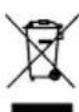
CTapoto enektpuecko n enektpoHno o60pydBaHe He Tp86Ba Da ce H3XBpbna 3aepHo c 6HTOBnTe OTnabu, a Tp86Ba Da ce cb6npa Nn3XBpbna paadennho!
- Cstapnte 6atepnn n akymnatopn, KOHTo He ca HenoBnKHO MOHTnpaHn B cTAPn ypei, Tp8Ba Da 6bDat N3BaDHeN npden npedabane 6e3 da ce pa3pyawabat! TxHoto N3Xbbpnahe e peIamentnpano ot 3akoha 3a 6atepnnte n akymnatopne.
CobteBHeHnIte,pecn. non3BaTeIne Ha eneKtpuecko H eNektpoHNO 6OpuyBaHc ca 3aKoHOBO 3aIbJxKeHN da H BbpHAT cne ynotpe6a.
KpaHnT noTppe6nte e OTROBOpEn 3a n3tpnBaHTo Ha nnHHTe My daHHo ot cTapn ypeN, KOHTo Tp8Ba Da 6bJe HxBpneH!
CmbonbHa 3aepkHata Kofa Ha KOJena O3Haaba, ye otnaBHTe ot enektpnueckoto n enektpoHHOT o6OpyDbaHe He Tp6Ba Da ce N3XBpNt 3aeHNo C 6ntOBte otnaBtu. -
EneKtpnueckoto n eneKtpoHHTo o6OpyBaHe MoKe da ce npedaba 6e3nnatHO Ha cneHInTe Mecta:
-
Np6nHn Cb6npaTeHH nyHKTOBe (Ha npHmep DboPOBE Ha 06uHcKn crpa#n)
LIDL Bn npednara onu nn 3a Bpshahe napekTHo BBnnaHne H MaraHnHte. BpshaHTo n 3XbPnHto ca6e3nnathn 3a Bac.
-MoKTe Da npedae Te Do TpH CTapn EneKtpueeckypea ot BceKn TIN ypeC MAKcHMaJIHa DblXknHa Ha p6a ot 25 caHTmEtpa 6e3 da KnyBATE HOB ypei OT npOn3BODntela, Hnn Da n npedae B dpyr OToPn3pan cb6npatehen NykT BBB Baunpaoh.
- 3a DonbHnHTeHNHe ycNoBna 3a BpueAne Ha npOn3BOIHTeHa HnCTpn6yTopn Ce O6bPheTe Km CbOTBeTHNaEHTbp 3a O6cnyKBAHe HA KNHeHTN.
AkoHOBNrTeneKTPueckn ypeCceIOCTABOr O npOn3BOHnTeHa YACTHO DOMAKHNCTBO,ToM MoKe Da opraHHnpa 6e3nnato H3BO3BaHe Ha CTapNRe EneKTPueckn ypeI npn nonCKBaHe OT KpaHnna Notpe6nten.3a centa ce CbPjxete COTEna 3a O6cnyXbaHe Ha KNHeHT Ha npOn3BOHnTeNa.
ToBaCeOTHACCaMo3aUpeHInTe,KOHToCEHHCTaHINpat HnpOABATBEBPoneNcKnCb03nCa npEIMeHa ebponeckataIupeKTHBa2012/19/EC.BCTpAHn3BbH EBponeNcKnCb03MOratdaCe npnlaratpa3nnuHN pa3nope6n3aHxBbpInHeHaOTnOdbuTeOTeNEKtpuecko neneKTPoHNOOBOpyDbAhe.
Yka3aHa 3a 3aKaHa 3a 6aTePnnte n akymyNatopnte (BattG)

CTapnte 6atepnn n akymynatopn He Tp86Ba da ce n3xBbPnT 3aepno c 6HTOBnTe ornaBtu, a Tp86Ba da ce cb6upat n n3XBbPnT pa3dennho!
3a 6e0nacno n3BaXdaHe Ha 6atepn Hnn aKymnatopn ot enektpnueckn ypei n 3a HOpmaun OTHOCHO Texnna Tnp, pecn. XmHuecka cnCTema, MOn, oBpHete BHNMaHne Ha DonbHnHTenHata HOpmaun B INHCTpyKUnTe 3a ekCnNoatau nn MOHTax.
Co6ctBeneHnnte,pecn. non3BaTeHnnte Ha 6aTeepHnnte n akymylatopnte ca 3akOHOBo 3aIbJxKeHN da Tn BbPHT cneynotpe6a.BpShaHeTo e orpaHnueHo Do npedabahe HApMaHn KOnHYeCTBa 3a DOMAKINHCTBOTO.
- Ctapnte 6atepnn Morat da cblbpkxt BpeHn BeuecTaB nn TeKKn Metan, KOHTo Morat da HaneCat BpeHn Ha OKONHata cpea nn Ha YOBeWkoTo 3dpabe. PeuNKnPaHrTo Ha Ctapnte 6atepnn n 3non3BaHeTo Ha cbIbpXaunTe ce b TRe pecypcn NOMara 3a 3auNTa Ha Te3n DBe BaxKn 6na.
CMBONbT Ha 3auepkhata Kofa Ha KOena O3Haayaba, ye 6atepnnte n akymyNatopne He Tpa6Ba da ce HxBbpnT 3aeHNO C6ntOBNTe OTnabu.
Ako 3haunte Hg, Cd nnn Pb cbso ca noi cnmbona 3a koqata 3a 6oknyk Ha konena, TOBA o3hauaba cneHOTO:
-Hg:Batepehra cIbpbka noeue oT,0005%KnBak
-Cd:BarepnaTcBbpxnobeyeo0,002%KaMm
- Pb: BaTepeHraTa cbIbpxka noboe ut 0,004 % onoBO
-
Akymylatopnte n 6aTepeHnTe MoKe da ce npedabat 6e3- nIaTHo HA CneHnTe MecTa:
-
Np6nHn Cb6npateHn nyHKTObe (HanpHmeP DboPoBe Ha o6uHckn crpa#n)
- Mara3HHa npoJax6Ha 6aTeepn n akymyataOpn
-ПунковеаВьшанeHaOБшаСистema3aВьшанeHa Stapn 6atepnHaурдn
-Пункза Вршае На пюиЗвдпетя (akо He e uнeHа ошata сстema 3a Вршае)
ToBa ce OTHACr cAmo 3a akymyIatopnTe n 6atepnTe, KOHTO CE npOABAT B Ebponecknra Cb03 n Ca npEIMET Ha ebponeckata NInpeKTHBa 2006/66/EC. B CTpaHn H3BbH Ebponecknra Cb03 MoT a ca npNarat pa3NHyn pa3-nopeD6n 3a n3XbPnHe Ha akymyIatopnTe n 6atepnTe.
15. OtpaHrahe Ha Hen3npabHOCTN
Günzburger Straße 69
D-89335 Ichenhausen
Axiotipie nEaTn,
Sac euxopaote noln euxapiotnon kai kaln etituxia kata tny epyaia me tn vea oac ouakeun.
Ynobsiei:
O kataokeuaotnacs uockeunc dev eutuvetai ouphiwa ToTov 1oxovta vpo nepi eouvnc npoiovw yia nieC, TIOU pokaouvtai oautn tn oukeun n aTO autn tn ouokun otic Exi n c PEPINTOWEIC:
Anaitouμevo εpyαλειo:
KλειδιΑλεν3mm(D)
H ywia-obnyo6 dev nepilaaavetai oTO avikel- mevo napadoonc.
Xaunnaote nky keaah tou epyaleiou (4) kai akivnttoioi-ote tn me tov neipo aosdianc (25).
Aaokaperte n BiBa akivntooinos (23).
ToTIOeTIOte Tn ywia o8nyo 90° (A) avapeo aOn Ia pa npioviou (6) kai otny npiotpeoevn β aon (13).
Aaokaperte to naigai aphiiaionc (26a).
Puθμiατe Tn βiδa προσαρμογης (26) tóo, μεχρι η γωνία μεταξύ λαμας προνιου (6) και περιστρεφόμενης βαοης (13) va ανερχειαι έπις 90°.
φi τ nai kaia to naigabi oafaiionc (26a).
9.3 KaθeTn KOTn 90° KAI NEPIOTpeΦoEvn βaon 0° (Eik. 1/2/3/6)
Ppoooxh! H kivntn paya avaotola (8a) npnei va akivntonoieitai otnv sowtepiikn 0eon yia ka-theta c konic 90°
Anaitouevoepyaaleio:
Kλεiδi Aλεv 3 mm (D)
AvoiTe Tn Biδa akivntooinos (8b) nC kivntns paYac avaToLa (8a) kai oPwTe Tny kivnt npay avaToLa (8a) npoc ta μεσa.
H kivnt npay aavaoTa (8a) npenei va akivntonoeitai oe toan anoataan atno nV nio eowtepiK thc, wate n meyiotn anoataan meta npayac avatoLa (8a) kai lapac npiovou (6) vaavpxetai 8 mm.
- Eλεγξτe πριν από την κοπή, ὄτι δεν εἰναι δυναίη μία σύγκρουση μετας οτης ράγας αναστολέα (8a) και της λάμας πριονιό (6).
- Σφiξτεξανa τη βδα ακινητοποιησς (8b).
ΦeptenVKeΦaHnTouεpyaIoiu (4)OtnvavwTeepnθeon.
ToTOnoTeTto µ λ 0 nou oEaTE va KoYETe eTTaHn E Tn paya avoToAea (8) kai naW OTnv TepiOTpeOpeyn Baoon (13).
- AKIVNTOIOINOte TO UAIKO ME TIC SIATAeic OuaophiIc (15) 0TO OTAePO TpanteZI npoviou (9), YIA VA anotpeyETn Mertakivnon kata n thiaikaia konnc. BA onmuio 9.12.
- Anaoaaiote tov diakottn aoaiaionc (2) kai natoe tov diakottn evpyoioinoc/ aeevyotoiinoc (1) ia va evpyoioiOeTo optep.
Kivote nV kephiah Tou epyaleiou (4) 1e Tn xeipola (3) opa kai pe eaop aieon npoc ta katw, ewc otou n Lapa Tpovio (6) ooknpwoi Tnv konn meow tou avti- KEiEvou epyaiaac.
Met to teao ts ciaikac ktonc, epte nky keaah Tou epyaleiou gava otnv entavw oen npepiac kai aphiote eueuthetaov diakottn evpyoioinons/ aneepeyoitoin ons (1).
Ppoooh!
Aoyou enavatakou exatnpiou n mnxavn metakiveitai autouata npoc ta eanaw. Mny afnvete tn xeipola (3) tto teao tskntc, aaia metakivote nyn keaahou epyaieiou apya kai aokwtau ckaopn.
service.GR@scheppach.com
Atouvone e-mail (CY):
service.CY@scheppach.com
Aeouon oepic GRCY):
GEORGE C SOLOMONIDES & SON LTD
PO.BOX 56236 / 169, LEONTIOS A
GR-3305 LIMASSOL/CYPRUS

Antn 8ieuovan www.lidl-service.com mnpoeite va kateBaoette auto kai noaaa aaaa eyyeipidia, bivteo npoiovw kai loyioik okyataoantc. Me tov kwika QR metaaivee aneuieiac stn oleiob eunpttnoc tou lidl (www.lidl-service.com) kai npoeite va avoiEe tic onnyiec xphonc oac eiaoyvtac tov kwiko npoiovtc (IAN) 499235_2204.
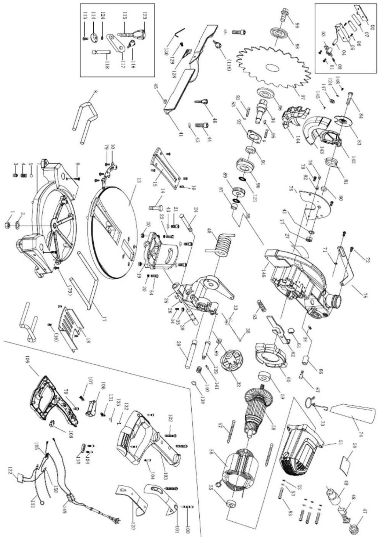
EC Declaration of Conformity Translation of the original EC declaration of conformity
Standard references:
EN 62841-1:2015; EN 62841-3-9:2015/A11:2017;
EN 55014-1:2017; EN 55014-2:2015; EN 61000-3-2:2014; EN 61000-3-3:2013
This declaration of conformity is issued under the sole responsibility of the manufacturer.
Subject to change without notice
Documents registrar: Tobias Ihl
Günzburgr Str. 69, D-89335 Ichenhausen
CE
SCHEPPACH GMBH
Günzburger Str. 69
D-89335 lichenhausen


Last Information Update - Stand der Informationen - Version des informations - Stand van de informatie - Stav informaci - Stan informaci - Stav informaci - Estado de las informaciones - Tilstand af information - Versione delle informazioni - Informacionk allasa - Stanje informacij
Zadnje informacije · Stadiul informaillor · DaTaHa HnHphiopMaun · Eksoon TwV nI npofoipow
Update: 09/2022 · Ident.-No.: 499235_2204_39012469915
IAN 499235_2204


- SCIE A ONGLET
- NAGIBNA PREKLOPNPA PILA
- HACTOJEHUNPKUYIAP
- EXPLANATION OF THE SYMBOLS ON THE EQUIPMENT
- INTRODUCTION
- MANUFACTURER
- SCHEPPACH GMBH
- DEAR CUSTOMER
- NOTE
- PLEASE CONSIDER
- DEVICE DESCRIPTION (FIG. 1-16)
- SCOPE OF DELIVERY
- PROPER USE
- WARNING
- SAFETY INFORMATION
- GENERAL POWER TOOL SAFETY WARNINGS
- SAVE ALL WARNINGS AND INSTRUCTIONS FOR FUTURE REFERENCE
- WORKPLACE SAFETY
- ELECTRICAL SAFETY
- PERSONAL SAFETY
- POWER TOOL USE AND CARE
- SERVICE
- SAFETY INSTRUCTIONS FOR CHOP AND LITRE SAWS
- SAFETY INSTRUCTIONS FOR THE HANDLING OF SAW BLADES
- ATTENTION: LASER BEAM DO NOT STARE INTO BEAM LASER CLASS 2
- PROTECT YOURSELF AND YOUR ENVIRONMENT FROM ACCIDENTS USING SUITABLE PRECAUTIONARY MEASURES
- SAFETY INSTRUCTIONS FOR HANDLING BATTERIES
- RESIDUAL RISKS
- THE ELECTRIC TOOL HAS BEEN BUILT ACCORDING TO STATE-OF-THE-ART AND THE RECOGNISED TECHNICAL SAFETY RULES. HOWEVER, INDIVIDUAL RESIDUAL RISKS CAN ARISE DURING OPERATION
- TECHNICAL DATA
- THE WORKPIECE MUST HAVE A MINIMUM HEIGHT OF 3MM AND A MINIMUM WIDTH OF 10MM
- MAKE SURE THAT THE WORKPIECE IS ALWAYS SECURED WITH THE CLAMPING DEVICE
- NOISE
- WEAR HEARING PROTECTION
- BEFORE COMMISSIONING
- ATTENTION
- ALWAYS ENSURE THAT THE MACHINE IS STABLE AND SECURED, E.G. BY FIXING IT TO A WORKBENCH
- 8.1 ASSEMBLING THE WORK PIECE CLAMPING DEVICE (FIG. 2)
- 8.2 ASSEMBLING THE WORK PIECE SUPPORTS (FIG. 2-3)
- 8.3 ASSEMBLING THE SUPPORT STAND (FIG. 2-3)
- 8.4 SAWDUST BAG (FIG. 4)
- CONNECTION TO AN EXTERNAL DUST EXTRACTION SYSTEM
- 8.5 CHECKING THE MOVABLE SAW BLADE GUARD SAFETY DEVICE (5)
- CHECK FUNCTION
- ATTACHMENT AND OPERATION
- 9.1 SETTING UP THE LITRE SAW (FIG.1 - 3)
- 9.2 PRECISION ADJUSTMENT OF THE STOP FOR CROSSCUT AT 90° (FIG. 5)
- TOOL REQUIRED
- STOP BRACKET NOT INCLUDED IN THE SCOPE OF DELIVERY
- 9.3 CROSSCUT 90° AND ROTARY TABLE 0° (FIG. 1/2/3/6) ATTENTION! TO MAKE 90° CROSSCUTS, THE ADJUSTABLE STOP RAIL (8A) MUST BE FIXED AT THE INNER POSITION
- 9.4 CROSSCUT AT 90° AND ROTARY TABLE BETWEEN 0° AND 45° (FIG. 1/2/3/6)
- TO MAKE 90° CROSSCUTS, THE ADJUSTABLE STOP RAIL (8A) MUST BE FIXED AT THE INNER POSITION
- 9.5 PRECISION ADJUSTMENT OF THE STOP FOR LITRE CUT AT 45° (FIG. 1/2/3/6/7/8)
- 9.6 MITRE CUT BETWEEN 0° AND 45° AND ROTARY TABLE BETWEEN 0° (FIG. 1/2/3/6)
- 9.7 MITRE CUT BETWEEN 0° AND 45° AND ROTARY TABLE BETWEEN 0° AND 45° (FIG. 1/2/3/6)
- FOR LITRE CUTS (INCLINED SAW HEAD), THE ADJUSTABLE STOP RAIL (8A) MUST BE FIXED IN THE OUTER POSITION
- FOR LITRE CUTS BETWEEN 0° AND 45° , MOUNT THE CLAMPING DEVICE (WORKPIECE CLAMP) (15) ONLY ON THE RIGHT SIDE
- 9.8 CHANGING THE SAW BLADE (FIG. 1/2/3/9/10)
- PULL OUT THE MAINS PLUG
- WEAR PROTECTIVE GLOVES WHEN CHANGING THE SAW BLADE! RISK OF INJURY
- 9.9 REPLACING LASER BATTERIES (FIG. 11)
- 9.10 SWITCHING ON/OFF ON THE LASER (FIG. 11)
- SWITCHING ON
- SWITCHING OFF
- 9.11 ADJUSTING THE LASER (FIG. 12)
- 9.12 USING THE CLAMPING HANDLE (FIG. 1/2)
- TRANSPORT (FIG. 13)
- MAINTENANCE
- GENERAL MAINTENANCE TASKS
- CLEANING THE MOVABLE SAW BLADE GUARD SAFETY DEVICE (5) (FIG. 16)
- REPLACING THE TABLE INSERT (10) (FIG. 14)
- DANGER
- IMMEDIATELY REPLACE DAMAGED TABLE INSERTS (10)
- BRUSH INSPECTION (FIG. 15)
- SERVICE INFORMATION
- STORAGE
- ELECTRICAL CONNECTION
- IMPORTANT INFORMATION
- DAMAGED ELECTRICAL CONNECTION CABLE
- SAFETY INFORMATION FOR REPLACING DAMAGED OR DEFECTIVE MAINS CONNECTION CABLES
- AC MOTOR
- DISPOSAL AND RECYCLING
- INFORMATION ON PACKAGING
- INFORMATION ON THE GERMAN ELECTRICAL AND ELECTRONIC EQUIPMENT ACT (ELECTROG)
- ELECTRICAL AND ELECTRONIC APPLIANCES DO NOT BELONG IN HOUSEHOLD WASTE, BUT SHOULD BE COLLECTED AND DISPOSED OF SEPARATELY
- INFORMATION ON THE GERMAN BATTERY ACT (BATTG)
- USED BATTERIES AND RECHARGEABLE BATTERIES DO NOT BELONG IN HOUSEHOLD WASTE, BUT SHOULD BE COLLECTED AND DISPOSED OF SEPARATELY
- TROUBLESHOOTING
- WARRANTY CERTIFICATE
- SERVICE-HOTLINE (GB): SERVICE-HOTLINE (IE): SERVICE-HOTLINE (NI)
- SERVICE-EMAIL (GB): SERVICE-EMAIL (IE): SERVICE-EMAIL (NI)
- SERVICE ADDRESS (GB): SERVICE ADDRESS (IE): SERVICE ADDRESS (NI)
- VEREHRTER KUNDE
- SERVICE-ADRESSE (DE)
- NOSYOU'RECOMMENDANDS
- GEACHTE KLANT
- TRANSPORT (AFB. 13)
- SERVICE-HOTLINE (BE)
- E-MAILADRES / EMAIL DU SERVICE (NL)
- E-MAILADRES (BE)
- SERVICEADRES / ADRESSE DU SERVICE (NL)
- VÁZÉNY ZÁKAZNIKU
- SZANOWNY KLIENCIE
- VÁZÉNY ZÁKAZNIK
- UPOZORNENIE
- KAREKUNDE
- 8.2 MONTERING OF EMNESUPPORTER (FIG. 2-3)
- SPOSTOVANI KUPEC
- NAPOTEK
- POSTOVANI KUPCI
- NAPOMENA
- OPREZ
- USLUGA-ADRESA (HR)
- CUPRINS
- INSTRUMENT NECESSITIES
- STIMATA CLIENTA, STIMATE CLIENT
- YKA3AHNA 3A 6E3ONACHOCT
- BESONACHOCHT HA PA6OTHOTO MACTO
- BEZONAACHOCT NPU PA6OTA C ENEKTPUECKN TOK
- BESONACHOCT HA XOPATA
- YNOTPE6A N 6OPABEHE C ENEKTPUECKNA NHCTPYMENT
- CEPBN3
- YKAAHNA 3A 6EOANACHOCT NPU 6OPABEHE C PEKEU NN DNCKOBE
- BHMAHHE: PASEPHOJIBUEHHE HE RIEJATE B IBUA PASEP KNAC 2
- PAAETE CE6E CN N OKONHOCTTA OT 3NNONONYKN UPE3 NOAXOJAUN NPEDNA3HM MEPKN
- YKA3AHNA 3A 6E3ONACHOC NPN 6OPABEHE C 6ATEPN
- OCTATBHN PNCKOBE
- PPEYNPEKDEHNE
- TEXHHUECKN DAHHN
- IETAINBIRP6BA DA E C BNCOUNHA OT NOHE 3 MM U NPOUNHA OR 10 MM
- 山YM
- HOCETE 3AUNTA 3A CNYUXA
- 8.3 MOTAX HA CTOIKATA (ΦNR. 2-3)
- 8.4 TOP6A 3A CTBPROTHH (FHR.4)
- CBBP3BAHE KBM BBHWHO NPAXON3CMYKBAHE
- 8.5 PNPOEPEKA HA NPEPNA3HOTO YCTPOICTBO - NOBNHEXE NPEPNA3NTEN HA PEXEUNN (5)
- PPOBEPE TE YHKNOHOHPAHTO
- KOHCTPYKUNU N O6CNYXBAHE
- 9.1 MONTAX HA TPNOHA C HSTERNAHE N REPYHR (FUR. 1-3)
- YKA3AHNE
- 9.2 ΦИНHA HACTPOIKA HA ORPAHNUNTETNA HANPEUHN PA3PE3 NOP NPAB BIBN 90° (FHR.5)
- HEO6XOGN M NHCTPYMENT
- ONOPEN BBRN HE E BKIIOUEH B O6EMA HA DOCTABKA-TA
- 9.3 HANPEHEN PASPE NOP NPAB BBRN 90° N BBPTAUE CE NNOT 0° (PHI.1/2/3/6)
- HEO6XOGUM UHCTPYMENT
- BHHMAHHE
- 9.4 HANPEHEN PASPES NOI NPAB BBRN 90° N BBPTAUE CE NNOT 0° - 45° (FNR.1/2/3/6)
- BHHMAHNE
- HEO6XOQNM UHCTPYMEHT
- 9.5 ΦИНА HABSTPOИKA HA ORPAHNUNTETЯ PA3PE3A CHAKNOH 45° (ФИR. 1/2/3/6/7/8)
- HEO6XOGM UHCTPYMENT
- ONOPEN BBRN HE E BKNIOUEN B O6EMA HA DOCTABKA-TA
- 9.6 PASPES C HAKNON 0° - 45° N BBPTRAU CE NNOT 0° (FNR. 1/2/3/6)
- BHIMAHNE
- BHIMAHHE
- HEO6XOQN M NHCTPYMENT
- 9.7 PASPE3 C HAUKNOH 0° - 45° N BBPTAUCH CE NNOT 0° - 45° (FNR.1/2/3/6)
- HEO6XOQNM UHCTPYMENT
- BHMUHNE
- 9.8 CMAHA HA PEXEUNN NNCK (FNR. 1/2/3/9/10)
- N3DBPNAUTE UENCENA
- 9.9 CMAHA HA 6ATEPNA HA NASEPA (FNR. 11)
- 9.10 BKNIOUBAHE/VSKNIOUBAHE HA NA3EPA (FNR. 11) BKNIOUBAHE
- N3KJIIOUBAHE
- 9.11 PERYNNPAHE HA NASEPA (PNR. 12)
- 9.12 YNPABLENNE HA QKCATOPA 3A DETAUN (FNR. 1/2)
- TPAHCNPTNPAHE (FNR. 13)
- NOPAPBKKCA
- PPEYNPEKDHNE
- 06UMEPKN 3A NOAPBKKA
- NOUCHTEBAHE HA NPEDNATAHTO YCTPONCTBO - NOABXKEN NPEDNATATEHN PEXEUNNA (5) (FNR. 16)
- IOPMAHA HA BNOXXKATA HA NNOTA (FMR. 14) ONACHOCT
- HE3A6ABHCMEHETE NOBPEHNTE BLOKKN HA NLOTA
- PPOBEPKA HA QETKATA (FHR. 15)
- CEPBN3HA HHΦOPMAΖΗ
- CBXPAAHEHNE
- ENEKTPMUECKO CBBP3BAHE
- BAXHH YKA3AHN
- IOBPEHEN CBBP3BAAW ENEKTPNUECKN NPOBOHNK
- YKA3AHN 3A 6E3ONACHOCT 3A CMHA HA NOBPEHN HN DEΦEKTHN PPOBOHNCN 3A CBBP3BAHE KBM MPEXATA
- BNRATEN HA NPOMEHNB TOK
- N3XBBPNAHE NPEUCNKLNPNAHE
- YKA3AHN3A ONAKOBKATA
- YKA3AHA 3A 3AKAOHA 3A ENEKTPNUECKOTO N ENEKTPOHNHO O6OPYDAHE (ELEKTROG)
- CTAPOTO ENEKTPUECKO N ENEKTPOHNO O60PYDBAHE HE TP86BA DA CE H3XBPBNA 3AEPHO C 6HTOBNTE OTNABU, A TP86BA DA CE CB6NPA NN3XBPBNA PAADENNHO
- YKA3AHA 3A 3AKAHA 3A 6ATEPNNTE N AKYMYNATOPNTE (BATTG)
- CTAPNTE 6ATEPNN N AKYMYNATOPN HE TP86BA DA CE N3XBBPNT 3AEPNO C 6HTOBNTE ORNABTU, A TP86BA DA CE CB6UPAT N N3XBBPNT PA3DENNHO
- OTPAHRAHE HA HEN3NPABHOCTN
- AXIOTIPIE NEATN
- YNOBSIEI
- ANAITOUΜEVO ΕPYΑΛΕΙO
- H YWIA-OBNYO6 DEV NEPILAAAVETAI OTO AVIKEL- MEVO NAPADOONC
- 9.3 KAΘETN KOTN 90° KAI NEPIOTPEΦOEVN ΒAON 0° (EIK. 1/2/3/6)
- ANAITOUEVOEPYAALEIO
- PPOOOH
- ATOUVONE E-MAIL (CY)
- AEOUON OEPIC GRCY)
- EC DECLARATION OF CONFORMITY TRANSLATION OF THE ORIGINAL EC DECLARATION OF CONFORMITY
- STANDARD REFERENCES
- EN 62841-1:2015; EN 62841-3-9:2015/A11:2017
- EN 55014-1:2017; EN 55014-2:2015; EN 61000-3-2:2014; EN 61000-3-3:2013
Brand : PARKSIDE
Model : PKS 1500 B3
Category : Electric saw