USER MANUAL TR 24 Li STIGA
EN Battery powered hand-held lawn trimmer / edge trimmer OPERATOR'S MANUAL
WARNING: read thoroughly the instruction booklet before using the machine.
MANUAL DE INSTRUCTIUNI

natural_image
Line drawing of a portable electronic device with ports and a screen (no text or symbols)
natural_image
Line drawing of a portable electronic device with attached cable and plug (no text or symbols)
- USO DELLA MACCHINA....10
6. USO DELLA MACCHINA
6.4 PRACOVNÍ ČINNOST
3.3 TYPESKILT PÅ PRODUKTET
- XEIPISTHPIA EΛΕΓΧΟΥ 11
- GENERAL ASPECTS ...... 1
- SAFETY REGULATIONS....2
- GETTING TO KNOW THE MACHINE ....6
3.1 Description of the machine and planned use.. 6
3.2 Safety signs....7
3.3 Product identification label 7
3.4 Main components....8
- ASSEMBLY 8
4.1 Assembly components....8
4.2 Rod installation....8
4.3 Handle assembly 8
4.4 Fitting the guard on the cutting means..... 9
4.5 Fitting the indicator on the cutting limit ..... 9
- CONTROLS....9
5.1 Throttle control lever....9
5.2 Throttle safety lever 9
- USING THE MACHINE 9
6.1 Preparation....9
6.2 Safety checks.... 10
6.3 Start-up 11
6.4 Operation 11
6.5 Advice for operation 12
6.6 Stop....12
6.7 After use.... 12
- ROUTINE MAINTENANCE....12
7.1 General information.... 12
7.2 Battery.... 13
7.3 Cleaning the machine and the motor...... 13
7.4 Nuts and bolts 13
- OCCASIONAL MAINTENANCE 13
8.1 Cutting means maintenance 14
8.2 Sharpening the line cutting knife 14
- STORING....14
9.1 Storing.... 14
9.2 Storing the battery.... 14
-
HANDLING AND TRANSPORTATION......14
-
ASSISTANCE AND REPAIRS 15
- WARRANTY COVERAGE....15
- MAINTENANCE TABLE....15
- TROUBLESHOOTING....16
- ACCESSORIES ON REQUEST....17
15.1 Batteries.... 17
15.2 Battery charger.... 17
1. GENERAL ASPECTS
1.1 HOW TO READ THE MANUAL
Some paragraphs in the manual contain important information regarding safety and operation and are emphasized in this manner:
NOTE or IMPORTANT These give details or further information on what has been previously indicated and aim to prevent damage to the machine or cause other damage.
The symbol highlights danger. Failure to observe the warning can lead to the risk of injury to oneself and others and/or damage.
The paragraphs highlighted in a square with grey spots indicate the optional characteristics not on all models documented in this manual. Check if the characteristic is on this model.
Whenever reference is made to a position on the machine "front", "back", "left" or "right" hand side, this refers to the operator's working position.
1.2 REFERENCES
The figures in these instructions for use are numbered 1, 2, 3, etc.
Components shown in the figures are marked A, B, C, etc.
Reference to component C in figure 2 is indicated with the wording: "See fig. 2.C" or simply "(Fig. 2.C)".
The figures are given as a guide only. The actual pieces can differ from those illustrated in this document.
1.2.2 Titles
The manual is divided into chapters and paragraphs. The title of paragraph "2.1 Training" is a sub-title of "2. Safety regulations". References to titles or paragraphs are marked with the abbreviation chap. or par. and the relevant number. Example: "chap. 2" or "par. 2.1."
2. SAFETY REGULATIONS
2.1 TRAINING
⚠️ Become familiar with the controls and the proper use of the machine. Learn how to stop the machine quickly. Failure to follow the warnings and instructions may result in fire and/or serious injury.
- Never allow the machine to be used by children or individuals with reduced physical, sensory or mental capabilities, or without experience and know-how, or individuals who do not have the necessary familiarity with the instructions. Local regulations may restrict the age of the operator.
- Never use the machine if the user is tired or unwell, or has taken medicine, drugs, alcohol or any substances which may slow their reflexes and compromise their judgement.
- Bear in mind that the operator or user is responsible for accidents or unexpected events occurring to other people or their property. It is the user's responsibility to assess the potential risk of the area where work is to be carried out and to take all the necessary precautions to ensure his own safety and that of others, particularly on slopes or rough, slippery and unstable ground.
- If the machine is sold or lent to others, make sure that the operator looks over the user instructions contained in this manual.
2.2 PREPARATION
Personal Protective Equipment (PPE)
- Always wear slim-fitting protective clothes with slash-proof protection, anti-vibration gloves, helmet, protective goggles, half-mask respirator, protective earplugs, cut resistant safety boots with non-slip soles.
- Use of hearing protections can reduce the ability to hear any warnings (shouting or alarms). Be careful of what occurs around you in the work area.
- Never wear scarves, shirts, necklaces, bracelets, loose flowing clothing, laces or ties or any hanging or flapping accessory that could catch in the machine or in any objects or materials in the work area.
- Tie your hair back if it is long.
Work area / Machine
- Thoroughly inspect the entire work area and remove anything that could be thrown by the machine or damage the cutting means/rotating units (stones, branches, iron wire, bones, etc.).
2.3 DURING OPERATION
Work area
-
Do not use the machine in environments at risk of explosion, in the presence of flammable liquids, gas or powder. Power tools create sparks which may ignite the dust or fumes.
• Work only in daylight or with good artificial light in good visibility conditions.
-
Keep persons, children and animals away from the working area. Get another adult to keep the children under supervision.
- Check that there is nobody within 15 metres of the machine's range of operation or within 30 metres for heavier cutting.
- Avoid working with wet grass, in the rain and when there is a risk of a thunderstorm, especially lightening.
- Do not expose the machine to rain or wet environments. Water entering a power tool will increase the risk of electric shock.
- Where possible, avoid working on wet, slippery ground or in any case on uneven or steep ground that does not guarantee stability for the operator.
- Pay careful attention to uneven ground (hills, dips), slopes, hidden hazards and obstacles that could limit visibility.
- Be very careful near ravines, ditches or embankments.
- Always work across the face of the slope and never up and down it, being very careful when changing direction, making sure the cutting means is always downstream.
- Look out for traffic when using the machine near the road.
Behaviour
- When working, the machine must always be firmly held in both hands, keeping the power unit on the right of the body and the cutting group below the line of the belt. Do not excessively extend arms.
- Avoid body contact with earthed or grounded surfaces, such as pipes, radiators,
cookers and refrigerators. There is an increased risk of electric shock if your body is earthed or grounded.
• Always use caution and take on a firm and well-balanced position.
- Never run, always walk.
• Always keep hands and feet away from the cutting means, when starting and when using the machine.
- Attention: the cutting means will continue to rotate for a few seconds after disengagement or after you have switched off the motor.
- Be careful of flying debris coming from the cutting means.
- Be careful of avoiding violent collisions between the cutting means and foreign objects/obstacles. Kickback may occur if the cutting means comes into contact with an obstacle/object. This contact can cause a rapid jerk in the opposite direction, pushing the cutting means up and towards the operator. Kickback can cause the operator to lose control of the machine, leading to serious consequences. To prevent kickbacks, take all appropriate precautions provided below:
– Firmly hold the machine, with two hands, and place your body and arms in a position that allows you to resist kickback.
- Do not extend the arms too high and do not cut above waist height.
- Only use the cutting means specified by the manufacturer.
– Follow the manufacturer's instructions concerning cutting means maintenance.
- Beware of injuries caused by devices used to cut the line length.
⚠️ If something breaks or an accident occurs during work, turn off the motor immediately and move the machine away to prevent further damage; if an accident occurs with injuries or third parties are injured, carry out the first aid measures most suitable for the situation immediately and contact the medical authorities for any necessary health care. Carefully remove any debris which could cause damage or injury to persons or animals if ignored.
Prolonged exposure to vibrations can cause injuries and neurovascular disorders (also called “Raynaud’s syndrome” or “white finger”), especially to people suffering from circulation disorders. The symptoms can regard the hands, wrists and fingers and are shown through loss of sensitivity, torpor, itching, pain and discolouring of or structural changes to the skin. These effects can be worsened by low ambient temperatures and/or by gripping the hand grips excessively tightly. If the symptoms occur, the length of time the machine is used must be reduced and a doctor consulted.
Use limitations
- Do not use the machine if you are unable to hold it with both hands or keep it steady on your legs while working.
- Never assemble metal cutting means. The use of metal or
rigid blades of any type with this machine is prohibited.
- Never use the machine with damaged, missing or incorrectly positioned guards.
- Don't use the machine if the attachments/tools are not installed in their seats.
- Never disengage, deactivate, remove or tamper with the safety systems/micro switches installed.
- Do not use the power tool if the switch does not turn it on and off. Any power tool that cannot be controlled with the switch is dangerous and must be repaired.
- Do not strain the machine too much and do not use a small machine for heavy-duty work. If you use the right machine, you will reduce the risk of hazards and improve the quality of your work.
Ensure regular maintenance and correct storage to maintain machine safety and high performance levels.
Maintenance
- Never use the machine with worn or damaged parts. Faulty or worn-out parts must always be replaced and never repaired.
- Be careful during adjustment of the machine to prevent entrapment of the fingers between moving parts of the cutting means and fixed parts of the machine.
The noise and vibration levels shown in these
instructions are the maximum levels for use of the machine. The use of an unbalanced cutting element, the excessive speed of movement, or the absence of maintenance have a significant influence on noise emissions and vibrations. Consequently, it is necessary to take preventive steps to eliminate possible damage due to high levels of noise and stress from vibration. Maintain the machine well, wear ear protection devices, and take breaks while working.
Storage
- To reduce fire risks, do not leave containers with debris inside a room.
2.5 RESIDUAL RISKS
Despite the compliance with all safety prescriptions, there may be additional hazards:
- danger of injuries to fingers and hands if caught in the rotation of the cutting line;
- danger of injuries to feet if struck by the cutting line,
- stones and soil projections.
2.6 BATTERY / BATTERY CHARGER
IMPORTANT The following safety instructions are in addition to the safety requirements provided in the specific battery and battery charger manual delivered with this machine.
- Only use battery chargers recommended by the manufacturer to recharge batteries. An inadequate battery charger may cause
electric shock, overheating or corrosive liquid to leak from the battery
- Use only batteries specifically designed for your power tool. The use of other batteries may cause injuries and fire risks.
- Make sure that the machine is switched off before inserting the battery. Inserting a battery in a machine which is switched on can cause a fire.
- Keep all unused batteries at a distance from paper clips, coins, keys, nails, screws or other small metal objects as contact with the same can cause short circuits. Short circuits between battery contacts can lead to explosion or fires.
- Never use the battery charger in environments in the presence of vapours, flammable substances or on easily flammable surfaces such as paper, fabric, etc. The battery charger heats up during recharging and may cause a fire.
- When transporting batteries, make sure the contacts never come into contact with each other and never use metal containers to transport them.
2.7 ENVIRONMENTAL PROTECTION
Safeguarding the environment must be a relevant and priority aspect of machine use, of benefit to the community and the environment we live in.
- Avoid being a disturbance to the neighbourhood. Use this machine at reasonable times of the day only (not early morning
or late evening when the noise could cause disturbance).
- Scrupulously comply with local regulations for the disposal of packaging, deteriorated parts or any elements with a strong environmental impact; this waste must not be disposed of as normal waste, it must be separated and taken to specified waste disposal centres where the material will be recycled.
- Scrupulously comply with local regulations for the disposal of waste materials
- When the machine is withdrawn from service, do not dump it in the environment, but take it to a waste disposal facility in accordance with the local regulations in force.
Do not throw electrical equipment away with domestic waste. According to the European Directive 2012/19/EU on electrical and electronic equipment waste and its implementation in compliance with national standards, old electrical equipment must be collected separately, for eco-compatible recycling. If electrical equipment is disposed of in a landfill or in the ground, the harmful substances can reach the water table and enter the food chain, damaging your health and well-being. For further information on the disposal of this product, contact your dealer or a domestic waste collection service.
At the end of their working life, dispose of batteries paying due attention to the environment. Batteries contain material classified as hazardous for you and the environment. They must be removed and disposed of separately at a facility that accepts lithium-ion batteries.
Separate waste collection of the products and packaging used allows the materials to be recycled and reused. Reuse of recycled materials help to prevent environmental pollution and reduces the demand for raw materials.
3. GETTING TO KNOW THE MACHINE
3.1 DESCRIPTION OF THE MACHINE AND PLANNED USE
This machine is a garden tool and more precisely a battery-powered portable grass /grass edge trimmer.
The machine is essentially composed of a motor which, employing a transmission shaft, drives a cutting device (cutting line head).
The cutting means works on a surface that is approximately parallel to the ground (in case of use as grass trimmer) or approximately perpendicular to the ground (in case of use as grass edge trimmer.
The operator can operate the machine and use the main controls, always keeping a safe distance from the cutting means.
3.1.1 Intended use
This machine was designed and manufactured for:
– cutting grass and non woody vegetation (e.g. around the edges of lawns, flowerbeds, walls, fences and small grassy areas);
– tidy up the cutting done using a mower;
– being used by one operator.
3.1.2 Improper use
Any other usage not in keeping with the above-mentioned ones may be hazardous and harm
persons and/or damage things. Examples of improper use may include, but are not limited to:
– using the machine for sweeping, tilting the cutting line head. The power of the motor could throw objects and small stones 15 metres or more, causing damage or injury to people;
– trimming hedges or other jobs in which the cutting means is not used at ground level;
– cutting and chopping trees, bushes and flowers;
– using the machine for cutting non-plant material;
– using the machine with the cutting means above the operator's belt level;
– using the machine in public gardens, parks, sports centres, on roadways, fields and woods;
– using cutting means other than those listed in the "Technical Data" table. Serious injury and wound hazard.
– using of the machine by more than one person.
IMPORTANT Improper use of the machine will invalidate the warranty, relieve the Manufacturer from all liability, and the user will consequently be liable for all and any damage or injury to himself or others.
3.1.3 User types
This machine is intended for use by consumers, i.e. non-professional operators. It is intended for "DIY" use only.
3.2 SAFETY SIGNS
The machine has various symbols on it (fig. 2). They are used to remind the operator of the behaviour to follow to use it with the necessary attention and caution.
Meaning of symbols:

WARNING! DANGER!
Failure to use this machine correctly can be hazardous for oneself and others

WARNING! Read the instruction manual before using the machine.

Anyone operating the machine under normal conditions for continuous daily use may be exposed to a noise level equal to or exceeding 85 dB (A). Use ear protection devices and goggles.
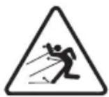
PROJECTION HAZARD!
Be careful of flying debris projected by the cutting means, that can cause serious injuries to persons or damage to things.
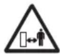
PROJECTION HAZARD!
Keep any people or pets at least 15 m away when using the machine!

Keep away from bystanders.

Do not leave the machine in the rain (or in damp conditions).
IMPORTANT Any damaged or illegible decals must be replaced. Order replacement decals from an authorised assistance centre.
3.3 PRODUCT IDENTIFICATION LABEL
The product identification label provides the following data (fig. 1):
- Sound power level
- Conformity marking
- Year of manufacture
- Type of machine
- Serial number
- Name and address of Manufacturer
- Article code
Write the identification data of the machine in the specific space on the label on the back of the cover page.
IMPORTANT Quote the information on the product identification label whenever you contact an authorised service workshop.
IMPORTANT The example of the Declaration of Conformity is provided on the last pages of the manual.
3.4 MAIN COMPONENTS
The machine is composed of a series of main components that have the following functions (Fig.1):
A. Power unit: it drives the cutting means through a transmission shaft.
B. Rod: it connects the rear hand grip to the power unit.
C. Cutting means: the element designed to cut the vegetation
1. Cutting line head: nylon line cutting means.
D. Cutting means guard: it is a safety device which prevents objects drawn up by the cutting means from being hurled away from the machine.
E. Front hand grip: semi-circular shaped, it is used to handle the machine.
F. Rear hand grip: used to handle the machine and equipped with the main on/off/acceleration control buttons.
G. Battery (if it is not supplied with the machine, see chapter 15 "accessories on request"): device that supplies electric current to the tool; its specifications and regulations for use are described in a specific manual.
H. Battery charger (if it is not supplied with the machine, see chapter 15 "accessories on request"): device used to recharge the battery.
4. ASSEMBLY
IMPORTANT The safety regulations to follow are described in chap. 2. Strictly comply with these indications to avoid serious risks or dangers.
For storage and transport purposes, some components of the machine are not installed in the factory and have to be assembled after unpacking. Follow the instructions below.
⚠ Unpacking and completing the assembly should be done on a flat and stable surface, with enough space for machine handling and its packaging, always making use of suitable equipment. Do not use the machine until all the indications provided in the “ASSEMBLY” section have been carried out.
4.1 ASSEMBLY COMPONENTS
The packaging includes assembly components.
4.1.1 Unpacking
- Carefully open the packaging, paying attention not to lose components.
- Consult the documentation in the box, including these instructions.
- Remove all the unassembled parts from the box.
- Remove the machine from the box.
- Dispose of the box and packaging in compliance with local regulations.
Before assembling, make sure the battery is not inserted in its housing.
4.2 ROD INSTALLATION
1.a Model TR 24 Li B
- Insert and push the lower part of the rod (Fig. 3.A) in the upper part (Fig. 3.B) until your hear the stop pin that blocks it in the right position.
NOTE The rod cannot be removed once it is assembled.
The rod length is adjustable (par. 6.1.3).
1.b Model TR 24 Li
- Align the upper part of the rod (Fig.
4.A) with the lower part (Fig. 4.B), following the direction of the arrows;
- push the lower part in the rod upper part;
- once inserted, tighten the knob securely (Fig. 4.C) following the direction of the arrow - closed padlock.
- Make sure the lower and upper part of the rod are carefully tightened.
4.3 HANDLE ASSEMBLY
4.3.1 Assembly of the front hand grip
1.a Model TR 24 Li B
- Insert the front hand grip (Fig. 5.A) on the shaft (Fig. 5.B), with the seat of the screw oriented on the left side.
1.b Model TR 24 Li
– Insert the front hand grip (Fig. 6.A) on the pre-assembled support (Fig. 6.B), with the seat of the screw oriented on the right side.
- Insert the screw and tighten the knob, without tightening it (Fig. 5.C, Fig. 6.C).
- Adjust the grip in the most ergonomic position for the operator (chapter 6.1.2).
- Tighten the knob.
4.4 FITTING THE GUARD ON THE CUTTING MEANS

Wear protective gloves.

Every cutting means must be fitted with a specific guard, as cated by the following directions of the Technical Data table.
- Place the guard (Fig. 7.A) on the holes on the power unit base (Fig. 7.B).
- Secure the guard (Fig. 7.A) fully tightening the screws (Fig. 7.C).
NOTE On the guard of the cutting means there is the following symbol:

Indicates the rotation direction of the cutting means.
4.5 FITTING THE INDICATOR ON THE CUTTING LIMIT
1.a Model TR 24 Li B
- Insert and fasten the two ends of the cutting limit indicator (Fig. 8.A) in their respective holes on the power unit (Fig. 8.B).
1.b Model TR 24 Li
– Slightly enlarge the cutting limit indicator (Fig. 9.A) and insert it in the space provided on the power unit (Fig. 9.B).
5. CONTROLS
5.1 THROTTLE CONTROL LEVER
It allows to start/stop the machine and simultaneously engages/disengages the cutting means.
The throttle control lever (Fig. 10.A). can only be used if the throttle safety lever is pressed simultaneously (Fig. 10.B).
For machine start up:
– Simultaneously push the regulator control lever and safety lever.

Starting the machine causes the cutting
ns to start rotating at the same time.
The machine stops automatically as the throttle control lever is released.
5.2 THROTTLE SAFETY LEVER
Throttle safety lever (Fig. 10.B) allows the throttle control lever to be used (Fig. 10.A).
6. USING THE MACHINE
IMPORTANT The safety regulations to follow are described in chap. 2. Strictly comply with these indications to avoid serious risks or dangers.
6.1 PREPARATION
Before starting work it is necessary to carry out several checks and operations to ensure you can work efficiently and in maximum safety:
- make sure the battery is not inserted in its housing;
- place the machine in a stable horizontal position on the ground;
- adjust the cutting diameter (par. 6.1.1)
-
adjust the machine from the ergonomic and functional points of view, in order to adapt it to the worker stature and to the type of work (par. 6.1.2 - par. 6.1.6);
-
check the battery (par. 6.1.7).
6.1.1 Adjustment of the cutting diameter (for cutting in motion only)
It is possible to set up a more or less wide cutting diameter (30 cm or 25 cm).
A larger cutting diameter helps to complete the work more quickly and it should be used in case of greater time to work.
A smaller cutting diameter optimises operating time and cutting speed.
To set the cutting diameter smaller:
- remove the line cutting knife (Fig. 11.A) from the cutting means guard (Fig. 11.B) unscrewing the screw (Fig. 11.C);
- rotate the line cutting knife by 180°
- only for model TR 24 Li B: Position the line cutting knife in the inner hole;
- re-assemble the line cutting knife (Fig. 11.A) on the cutting means guard (Fig. 11.B).
6.1.2 Regulating the front hand grip
- Remove the knob (Fig. 12.A);
2.a For model TR 24 Li B:
- move the front hand grip in the most ergonomic position for the operator;
2.b For model TR 24 Li:
- move and/or direct the hand grip in the most ergonomic position for the operator; it is possible to direct the hand grip only forwards.
- Tighten the knob (Fig. 12.A).
6.1.3 Rod length regulation (only for model TR 24 Li B)
- Loosen the knob (Fig. 13.A) following the direction of the arrow - open padlock.
- pull or push the rod (Fig. 13.B) until it reaches the desired length;
- when the adjustment is complete, tighten the hand grip following the direction of the arrow - closed padlock.
6.1.4 Rod height regulation (only for model TR 24 Li)
- Press the button (Fig. 14.A) and adjust the rod height (Fig. 14.B) on one of the four possible positions (Fig. 14.C);
- make sure the rod is firmly locked.
6.1.5 Aligning the cutting device
The cutting means orientation allows to switch from grass trimmer mode to grass edge trimmer mode, and vice versa, while working (Par. 3.1).
How to work in grass trimmer mode:
1.a For model TR 24 Li:
- Press the button (Fig. 15.A);
- Rotate the cutting means (Fig. 15.B) by 90^ , making sure it stays locked in the position.
1.b For model TR 24 Li B:
– Pull the upper sleeve backwards (Fig. 16.A);
- Rotate the lower part of the rod by 180^ (Fig. 16.B), making sure it stays locked in the position.
⚠ Perform this operation when the machine is turned off and the cutting means is still.
6.1.6 Cutting limit indicator adjustment (only for model TR 24 Li B)
- Rotate forwards the cutting limit indicator (Fig. 17.A) when working near trees, kerbs or fences, to avoid the impact with the cutting means.
6.1.7 Checking the battery
Before each use:
– check the battery charge status according to the instructions in the battery booklet.
6.2 SAFETY CHECKS
Run the following safety checks and check that the results correspond to those outlined on the tables.
Always carry out the safety checks before use.
6.2.1 General check
| Object Result | |
| Hand grips (Fig. 1.E) Clean | dry and fixed firmly to the machine. |
| Cutting means guard (Fig. 1.D) | Correctly and securely fit to the machine, not worn/ deteriorated or damaged. |
| Screws on the machine Correctly tightened (not loose) |
| Cutting means (Fig. 1.C) Clean | clean, not damaged or worn. |
| Battery (Fig. 1.G) No damage to the casing, no liquid leakage |
| Cooling air ducts (par. 7.3) Not clogged |
| Machine No signs of damage or wear |
| Throttle control lever (Fig. 10.A), throttle safety lever (Fig. 10.B) | The levers must move freely and not be forced. |
| Test driving | No abnormal vibrations. No abnormal sound |
6.2.2 Machine operating test
| Action Result | |
| 1. Start the machine (par. 6.3);2. Release the throttle control lever (Fig. 10.A) and throttle safety lever (Fig. 10.B). | 1. The cutting means should move.2. The levers should return automatically and rapidly to the neutral position, the machine and the cutting means should stop. |
| Only activate the throttle control lever (Fig. 10.A) | The throttle control lever remains blocked. |
⚠️ If any of the results fail to match the indications provided in the tables below, do not use the machine! Take it to a service centre to be checked and repaired if necessary.
6.3 START-UP
- Make sure the cutting means is not touching the ground or any other object;
- fit the battery inside its housing correctly (par. 7.2.3);
- simultaneously activate the throttle control lever (Fig. 10.A) and throttle safety lever (Fig. 10.B).
NOTE At every start up new line is automatically released (par. 6.4.2).
6.4 OPERATION
NOTE Before tackling a mowing job for the first time, get to know the machine, learn the most suitable cutting techniques, grip the machine firmly and make the movements required by the job.
To use the machine proceed as follows: – always hold the machine firmly with two hands, using the cutting unit below the operator's belt level.
NOTE During use, the battery is protected against total drainage with a protective device that switches off the machine and stops it from working.
NOTE Battery power reserve (and therefore the cuttable vegetation surface before recharging is required) depends on many factors described in (par. 7.2.1).
6.4.1 Work techniques
⚠ Use ONLY nylon lines. The use of metal lines, plasticised metal lines and/or lines that are not suitable for the head can cause serious injuries and wounds.
a. Cutting in motion (Scything)
- Make sure the cutting means is in grass trimmer mode (par. 6.1.5);
– proceed at a regular pace, with a circular motion similar to a traditional scythe, without tilting the cutting line head during the operation (Fig. 18).
First try cutting at the right height in a small area, so as to then achieve a uniform cutting height keeping the cutting line head at a constant distance from the ground.
For heavier cutting it can be useful to tilt the cutting line head to the left by about 30^ .
Do not work in this way if there is the possibility of causing objects to be thrown, which could harm people, animals or cause damage.
b. Precision cutting (Trimming)
Keep the machine slightly tilted so that the lower part of the cutting line head does not touch the ground and the cutting line is at the required point, always keeping the cutting means at a distance from the operator.
c. Cutting near fences/foundations
- Adjust the cutting limit indicator (if applicable, par. 6.1.6);
– move the cutting line head slowly towards fences, posts, rocks, walls, etc. without hitting them hard (Fig. 17).
If the line strikes a solid object it could break or become worn; if it gets tangled in a fence it could break suddenly. In any case, cutting around pavements, foundations, walls, etc. can cause greater wear than normal to the line.
d. Cutting around trees
- Adjust the cutting limit indicator (if applicable, par. 6.1.6);
- walk round the tree from left to right, approaching the trunks slowly so as not to strike the tree with the line and keeping the cutting line head tilted forward slightly.
Remember that the nylon line could lop off or damage small shrubs and that the impact of the
nylon line against the trunk of bushes or trees with soft bark could seriously damage the plant.
6.4.2 Adjusting the length of the cutting line head during work
Head line length should be adjusted:
– when the line is consumed and becomes shorter;
– when motor rotation seems higher than normal;
– when cutting efficiency seems reduced.
• Automatic line release
This machine is fitted with an automatic line release head.
To release new line:
- Stop the machine (par. 6.6);
- wait for two seconds and restart the machine.
The released line is about 6.35 mm.
Repeat the procedure until the line length reaches the line cutting knife that will cut any exceeding length.
- Manual line release
To release new line:
- Stop the machine (par. 6.6);
- remove the battery from its housing (par 7.2.2);
- press the button on the line head (Fig. 19.A) and, at the same time, pull the line manually for the length that is necessary to reach the line cutting knife (Fig. 19.B);
- bring back the machine to the working position;
- Fit the battery inside its housing (par. 7.2.3).
During use it is best to periodically remove weeds that wrap around the machine to avoid motor overheating (Fig. 1.A), due to grass caught under the cutting means guard (Fig. 1.D).
Proceed as follows:
- stop the machine (par. 6.6);
- remove the battery (par.7.2.2);
- wear work gloves;
– remove the caught-up grass with a screwdriver to allow the motor to be properly cooled.
6.6 STOP
To stop the machine:
- Release the throttle control lever (Fig. 10.A);
- Wait until the cutting means stops.
When you have stopped the machine, it will take a few seconds for the cutting means to stop.
IMPORTANT Always stop the machine when moving between work areas.
6.7 AFTER USE
- Remove the battery from its housing and recharge it (par 7.2.2).
- Allow the motor to cool before storing in an enclosed space.
- Clean (par. 7.3).
- Check there are no loose or damaged components. If necessary, replace the damaged components and tighten any screws and loose bolts or contact the authorised service centre.
IMPORTANT Always remove the battery (par 7.2.2) whenever you leave the machine unused or unattended.
7. ROUTINE MAINTENANCE
IMPORTANT The safety regulations to follow are described in chap. 2. Strictly comply with these indications to avoid serious risks or dangers.
⚠️ Prior to carrying out any maintenance operation, you need to:
- Stop the machine;
- remove the battery from its housing and recharge it (par 7.2.2).
- allow the motor to cool before storing in an enclosed space;
- use suitable clothing, protective gloves and goggles;
- read the relevant instructions;
- The frequency and types of maintenance are summarised in the "Maintenance Table" (chapter 13). The table will help you maintain your machine's safety and performance. It summarises the main interventions to be made and the frequency applicable to each of them. Carry out the relevant task as soon as it is scheduled to be performed.
– The use of non-genuine spare parts and attachments could adversely affect machine operation and safety. The manufacturer
declines all liability for any damage or injuries caused by these products.
– Genuine spare parts are supplied by authorised assistance workshops and dealers.
IMPORTANT Any maintenance and adjustment operations not described in this manual must be carried out by your dealer or Authorised Service Centre.
7.2 BATTERY
7.2.1 Battery power reserve
Battery power reserve (and therefore the cuttable vegetation surface before recharging is required) mainly depends on:
a. environmental factors, that cause higher energy requirements:
– cutting, high, wet vegetation;
b. operator behaviour that should be avoided:
– switching the machine on and off frequently whilst working;
- adopting a cutting technique that is unsuitable for the work to be performed (par. 6.4);
To optimise battery power reserve it is always recommended to:
• cut the grass when dry;
- use the most appropriate technique for the work to be performed
If the need arises to use the machine for sessions which exceed the capability of a standard battery, it is possible to:
• purchase a second standard battery to immediately replace the discharged battery, without compromising the continuity of operations;
• purchase a battery with an extended power reserve compared to the standard version (par. 15.1).
7.2.2 Battery removal and recharging
- Press the retainer tab in the battery (Fig. 20.A), and remove the battery (Fig. 20.B);
- fit the battery (Fig. 21.A) in the battery charger housing (Fig. 21.B);
- connect the battery charger (Fig. 21.B) to a power socket with the voltage indicated on the rating plate.
- fully charge the battery according to the instructions in the battery/battery charger booklet.
NOTE The battery is equipped with a guard that inhibits recharging if the environmental temperature is not between 0 and +45 °C.
NOTE The battery can be recharged at any time, even partially, with no risk of damaging it.
7.2.3 Refitting the battery on the machine
When recharging is completed:
- Remove the battery (Fig. 22.A) from the housing in the battery charger (do not keep recharging when recharging is completed);
- disconnect the battery charger (Fig. 22.B) from the electrical mains;
- fit the battery (Fig. 23.B) in its housing pressing down until you hear it click firmly into position which ensures the electrical contact.
7.3 CLEANING THE MACHINE AND THE MOTOR
- Always clean the machine after use with a damp cloth dipped in neutral detergent.
- Remove all traces of humidity using a soft damp cloth. Humidity can generate risks of electric shocks.
- Do not use aggressive detergents or solvents to clean the plastic parts or hand grips.
- To reduce fire hazards, keep the lawnmower and, in particular, the motor free of grass, leaves, or excessive grease;
- To avoid overheating and damage to the motor or the battery, always keep the cooling air vents clean and free of debris.
- Do not spray water onto the motor and electrical components and prevent them from getting wet.
7.4 NUTS AND BOLTS
- Keep all nuts, bolts and screws tight to be sure the equipment is in safe working condition.
- Check regularly that the handles are fixed firmly.
8. OCCASIONAL MAINTENANCE
Prior to carrying out any maintenance operation, you need to:
8.1 CUTTING MEANS MAINTENANCE
Cutting means displaying the code indicated on the Technical Data table should be used on this machine.
Given product evolution, the cutting means mentioned in the "Technical Data" table may be replaced in time with others having similar interchangeable and operating safety features.
Do not touch the cutting means until the battery has been removed and the cutting means is completely stationary.
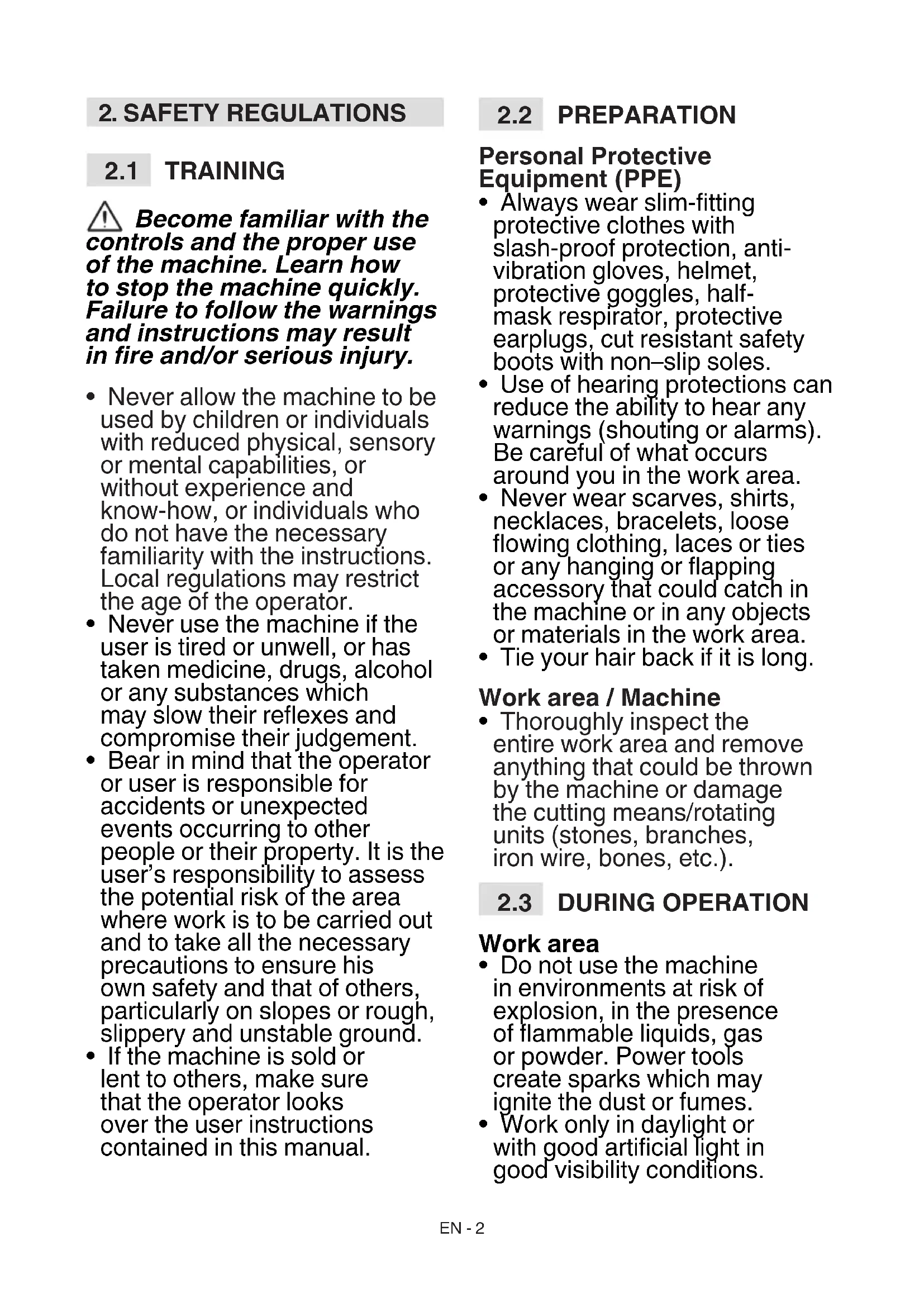
8.1.1 Replacing the reel of the cutting line head
- Press the two side tabs (Fig. 24.A) and remove the cover (Fig. 24.B);
- Remove the reel (Fig. 24.C);
- insert the new reel (Fig. 25.A), making sure the line extremity exits the head hole (Fig. 25.B);
- Refit the cover (Fig. 25.C) insert the two side tabs (Fig. 25.D) in the cutting line head openings (Fig. 25.E).
8.1.2 Replacing the cutting line head
- Remove the reel (par. 8.1.1);
- remove the line left inside;
- only use a line with diameter of 1.65 mm and cut 3 m of length.
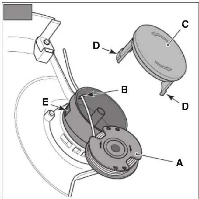
- Insert one line extremity in the hole located inside the reel (Fig. 26.A);
- roll the line in the clockwise direction as specified by the arrows (Fig. 26.B) and let it stick out of about 15 cm from the reel;
- connect it with one of the anchorage sites (Fig. 26.C) on the reel;
- reposition the reel and reassemble the cover (cap 8.1.1).
8.2 SHARPENING THE LINE CUTTING KNIFE
-
Remove the line cutting knife (Fig. 11.A) from the cutting means guard (Fig. 11.B) unscrewing the screw (Fig. 11.C);
-
Fix the line cutting knife in a vice and sharpen it using a flat file, being careful to retain the original cutting angle;
- Re-assemble the line cutting knife (Fig. 11.A) on the cutting means guard (Fig. 11.B).
9. STORING
IMPORTANT The safety regulations to follow are described in chap. 2. Strictly comply with these indications to avoid serious risks or dangers.
9.1 STORING
When the machine is to be stored away:
- Remove the battery from its housing and recharge it (par. 7.2.2).
- Allow the motor to cool before storing in an enclosed space.
- Clean (par. 7.3).
- Check there are no loose or damaged components. If necessary, replace the damaged components and tighten any screws and loose bolts or contact the authorised service centre.
- Store the machine:
-in a dry place
– protected from inclement weather
– in a place where children cannot get to it
– making sure that keys or tools used for maintenance are removed.
9.2 STORING THE BATTERY
The battery must be kept in a cool, shaded place without humidity.
NOTE If unused for any length of time, recharge the battery every two months to prolong its working life.
- HANDLING AND TRANSPORTATION
Whenever the machine is to be handled or transported you must:
- Stop the machine (par. 6.6);
– remove the battery from its housing and recharge it (par. 7.2.2);
- wear heavy work gloves;
– only hold the machine using the hand grips and position the cutting means in the opposite direction to that used during operations.
When transporting the machine on a vehicle, always:
– position it so that it can not cause a hazard for anybody.
11. ASSISTANCE AND REPAIRS
This manual provides all the necessary information to run the machine and for correct basic maintenance operations which can be performed by the user. Any regulations and maintenance operations not described herein must be carried out by your Dealer or Authorised Service Centre, which have the necessary knowledge and equipment to ensure that the work is carried out correctly, maintaining the correct degree of safety and the original operating conditions of the machine. Any operations performed in unauthorised centres or by unqualified persons will totally invalidate the Warranty and all obligations and responsibilities of the Manufacturer.
- Only authorised service workshops can carry out guaranteed repairs and maintenance.
- The authorised service workshops only use genuine spare parts. Genuine spare parts and attachments have been designed specifically for machines.
- Non-genuine spare parts and accessories are not approved. Use of non-genuine spare parts and accessories cause the warranty to expire.
- It is advisable to send your machine once a year to an authorised service workshop for servicing, assistance and safety device inspection.
12. WARRANTY COVERAGE
The warranty covers all material and manufacturing defects. The user must follow all the instructions provided in the accompanying documentation.
The warranty does not cover damages caused by:
- Failure to become familiar with the documentation accompanying the machine.
- Carelessness.
- Incorrect or prohibited use or assembly.
- Use of non-genuine spare parts.
- Use of attachments not supplied or approved by the manufacturer.
The warranty does not cover:
- Normal wear and tear of consumables, such as cutting means, safety bolts.
• Normal wear and tear.
The purchaser is protected by his or her own national legislation. The purchaser's rights under the national laws or his or her own country are not in any way restricted by this warranty.
- MAINTENANCE TABLE
| Intervention Frequency Notes | | |
| MACHINE |
| Check all fasteners | Before each use par. | 7.4 |
| Safety checks/check controls | Before each use par. | 6.2 |
| Check the cutting means guard. | Before each use par. | 6.2.1 |
| Checking the cutting means | Before each use par. | 6.2.1 |
| Check the battery charge status | Before each use * | |
| Recharge the battery | After each use par. | 7.2.2* |
| Cleaning the machine and the motor | After each use par. | 7.3 |
| Checking for any damage to the machine. If necessary, contact the authorised service centre. | After each use - | |
* Refer to the battery/battery charger manual.
14. TROUBLESHOOTING
| PROBLEM PROBALE CAUSE SOLUTION | |
| 1. The cutting means is stationary and the machine does not start when the throttle control lever and throttle safety lever are engaged | Battery is not inserted or is inserted incorrectly | Make sure that the battery is inserted correctly (par. 7.2.3) |
| Low battery Check the battery status and recharge if necessary (par. 7.2.2) |
| The separable rod was not fully or properly inserted in its housing | Make sure the separable rod was installed and correctly inserted (par. 4.2) |
| Defective throttle control lever/throttle safety lever | Do not use the machine. Immediately turn off the machine remove the battery and contact a service centre. |
| Machine damaged. Do not use the machine. Immediately turn off the machine remove the battery and contact a service centre. |
| 2. Motor overheating | Grass caught under the cutting means guard | Remove caught grass (par. 6.5) |
| 3. Grass accumulates around the power unit housing and the cutting line head | Too high grass is being cut close to the ground | Cut tall grass with a top down movement to avoid accumulations. |
| 4. The line is not released when the automatic release is turned on | The line is stuck to itself Lubricate with silicone spray |
| Not enough line on the reel or reel empty | Replace the reel (chap. 8.1.1) or the line (chap. 8.1.2) |
| The line is worn and too short Release the line manually (chap. 6.4.2.) |
| The line is tangled on the reel or broken | Remove the line from the reel and rewind it (chapter 8.1.2) |
| 5. The cutting means comes into contact with a foreign body. | - Turn off the machine, remove the battery and:- inspect for damage;- check for and tighten any loose parts;- have all replacements or repairs carried out by an authorised service centre. |
| 6. Excessive noise and/or vibration is experienced whilst working | Loose or damaged parts. Turn off the machine, remove the battery and:- inspect for damage;- check for and tighten any loose parts;- have all replacements or repairs carried out by an authorised service centre. |
| 7. The machine gives off smoke whilst working | Machine damaged. Do not use the machine. Immediately turn off the machine remove the battery and contact a service centre. |
| 8. Battery power reserve is low | Severe working conditions requiring greater current absorption | Optimise operations (par. 7.2.1) |
| Battery is insufficient for operating requirements | Use a second battery or extended battery (par. 15.1) |
| Decrease in battery capacity Purchase a new battery |
If problems persist after having performed the above operations, contact your dealer.
| PROBLEM PROBABLE CAUSE SOLUTION | |
| 9. The battery charger is not recharging the battery | Battery is not correctly inserted in the battery charger | Check it is correctly inserted (par. 7.2.3) |
| Unsuitable environmental conditions Recharge the battery in places with suitable temperatures (see battery/battery charger instruction manual) |
| Dirty contacts Clean the contacts | |
| The battery charger is not energised | Check it is plugged in and the power socket is energised |
| Faulty battery charger Replace with an original spare part |
| - | If the problem persists, refer to the battery/battery charger manual |
If problems persist after having performed the above operations, contact your dealer.
15. ACCESSORIES ON REQUEST
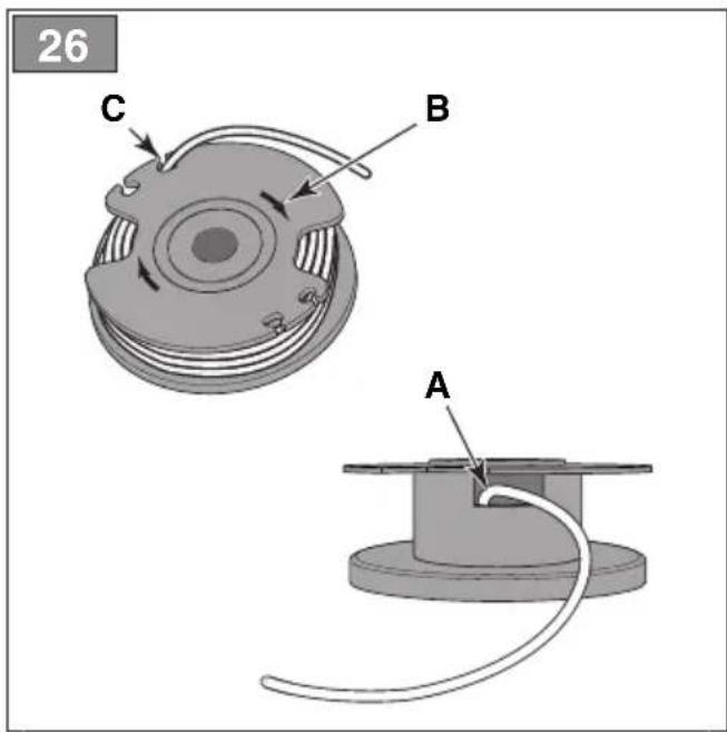
15.1 BATTERIES
Different capacity batteries are available to suit specific operating requirements (Fig. 27). The list of approved batteries for this machine is found in the "Technical Data" table.
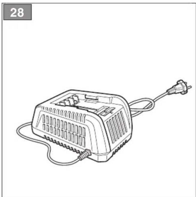
15.2 BATTERY CHARGER
Device used to recharge the battery (Fig. 28).
ÍNDICE
1.1 KUIDAS KASUTUSJUHENDIT LUGEDA
5.2 GAASI OHUTUSNUPP
- SÄÄNNÖLLINEN HUOLTO....13
- YLIMÄÄRÄINEN HUOLTO....14
10. MANUTENTION ET TRANSPORT
7. PLĀNOTĀ TEHNISKĀ APKOPE
2.7 BESCHERMING VAN DE OMGEVING
7.4 MOEREN EN SCHROEVEN VOOR BEVESTIGING
- GENERELT.... 1
- SIKKERHETSBESTEMMELSER....2
- BLI KJENT MED MASKINEN....6
- ORDINÆRT VEDLIKEHOLD 12
- EKSTRAORDINÆRT VEDLIKEHOLD ...... 13
2.4 VEDLIKEHOLD, LAGRING
3. BLI KJENT MED MASKINEN
3.1 BESKRIVELSE AV MASKINEN OG BEREGNET BRUK
7. ORDINÆRT VEDLIKEHOLD
7.1 GENERELT
13. VEDLIKEHOLDSTABELL
6.1 CZYNNOŚCI WSTĘPNE
6.4 PRACOVNÁ ČINNOST
INNEHÅLLSFÖRTECKNING
Intertek Testing Services Shangai
Building no.86, 1198 Qinzhou Road (North), Shangai 200233 - China
• EMCD: 2014/30/EU
• RohS II: 2011/65/EU
EN • The content and images in this User Manual were produced expressly for STIGA SpA and are protected by copyright – any unauthorised reproduction or modification to the document, either partially or in full, is prohibited.