SV 15YC - Sander HITACHI - Free user manual and instructions
Find the device manual for free SV 15YC HITACHI in PDF.
User questions about SV 15YC HITACHI
0 question about this device. Answer the ones you know or ask your own.
Ask a new question about this device
Download the instructions for your Sander in PDF format for free! Find your manual SV 15YC - HITACHI and take your electronic device back in hand. On this page are published all the documents necessary for the use of your device. SV 15YC by HITACHI.
USER MANUAL SV 15YC HITACHI
(Original instructions)
GENERAL POWER TOOL SAFETY WARNINGS

WARNING
Read all safety warnings, instructions, illustrations and specifi cations provided with this power tool.
Failure to follow all instructions listed below may result in electric shock, fire and/or serious injury.
Save all warnings and instructions for future reference.
The term "power tool" in the warnings refers to your mains-operated (cored) power tool or battery-operated (cordless) power tool.
1) Work area safety
a) Keep work area clean and well lit.
Cluttered or dark areas invite accidents.
b) Do not operate power tools in explosive atmospheres, such as in the presence of flammable liquids, gases or dust.
Power tools create sparks which may ignite the dust or fumes.
c) Keep children and bystanders away while operating a power tool.
Distractions can cause you to lose control.
2) Electrical safety
a) Power tool plugs must match the outlet. Never modify the plug in any way. Do not use any adapter plugs with earthed (grounded) power tools.
Unmodified plugs and matching outlets will reduce risk of electric shock.
b) Avoid body contact with earthed or grounded surfaces, such as pipes, radiators, ranges and refrigerators.
There is an increased risk of electric shock if your body is earthed or grounded.
c) Do not expose power tools to rain or wet conditions.
Water entering a power tool will increase the risk of electric shock.
d) Do not abuse the cord. Never use the cord for carrying, pulling or unplugging the power tool.
Keep cord away from heat, oil, sharp edges or moving parts.
Damaged or entangled cords increase the risk of electric shock.
e) When operating a power tool outdoors, use an extension cord suitable for outdoor use.
Use of a cord suitable for outdoor use reduces the risk of electric shock.
f) If operating a power tool in a damp location is unavoidable, use a residual current device (RCD) protected supply.
Use of an RCD reduces the risk of electric shock.
3) Personal safety
a) Stay alert, watch what you are doing and use common sense when operating a power tool.
Do not use a power tool while you are tired or under the influence of drugs, alcohol or medication.
A moment of inattention while operating power tools may result in serious personal injury.
b) Use personal protective equipment. Always wear eye protection.
Protective equipment such as a dust mask, non-skid safety shoes, hard hat or hearing protection used for appropriate conditions will reduce personal injuries.
c) Prevent unintentional starting. Ensure the switch is in the off -position before connecting to power source and/or battery pack, picking up or carrying the tool.
Carrying power tools with your finger on the switch or energising power tools that have the switch on invites accidents.
d) Remove any adjusting key or wrench before turning the power tool on.
A wrench or a key left attached to a rotating part of the power tool may result in personal injury.
e) Do not overreach. Keep proper footing and balance at all times.
This enables better control of the power tool in unexpected situations.
f) Dress properly. Do not wear loose clothing or jewellery. Keep your hair and clothing away from moving parts.
Loose clothes, jewellery or long hair can be caught in moving parts.
g) If devices are provided for the connection of dust extraction and collection facilities, ensure these are connected and properly used.
Use of dust collection can reduce dust-related hazards.
h) Do not let familiarity gained from frequent use of tools allow you to become complacent and ignore tool safety principles.
A careless action can cause severe injury within a fraction of a second.
4) Power tool use and care
a) Do not force the power tool. Use the correct power tool for your application.
The correct power tool will do the job better and safer at the rate for which it was designed.
b) Do not use the power tool if the switch does not turn it on and off.
Any power tool that cannot be controlled with the switch is dangerous and must be repaired.
c) Disconnect the plug from the power source and/ or remove the battery pack, if detachable, from the power tool before making any adjustments, changing accessories, or storing power tools.
Such preventive safety measures reduce the risk of starting the power tool accidentally.
d) Store idle power tools out of the reach of children and do not allow persons unfamiliar with the power tool or these instructions to operate the power tool.
Power tools are dangerous in the hands of untrained users.
e) Maintain power tools and accessories. Check for misalignment or binding of moving parts, breakage of parts and any other condition that may affect the power tool's operation. If damaged, have the power tool repaired before use.
Many accidents are caused by poorly maintained power tools.
f) Keep cutting tools sharp and clean.
Properly maintained cutting tools with sharp cutting edges are less likely to bind and are easier to control.
g) Use the power tool, accessories and tool bits etc. in accordance with these instructions, taking into account the working conditions and the work to be performed.
Use of the power tool for operations diff erent from those intended could result in a hazardous situation.
h) Keep handles and grasping surfaces dry, clean and free from oil and grease.
Slippery handles and grasping surfaces do not allow for safe handling and control of the tool in unexpected situations.
5) Service
a) Have your power tool serviced by a qualified repair person using only identical replacement parts.
This will ensure that the safety of the power tool is maintained.
PRECAUTION
Keep children and infirm persons away.
When not in use, tools should be stored out of reach of children and infirm persons.
ADDITIONAL SAFETY WARNINGS
- Ensure that the power source to be utilized conforms to the power requirements specified on the product nameplate.
- Ensure that the power switch is in the OFF position.
If the plug is connected to a receptacle while the power switch is in the ON position, the power tool will start operating immediately, which could cause a serious accident.
- To prevent accidents, the plug is disconnected from the receptacle before any adjustments, conversions or servicing are performed.
- The work place must be well ventilated.
- Follow national requirements for the materials you want to work with.
- When the work area is removed from the power source, use an extension cord of sufficient thickness and rated capacity. The extension cord should be kept as short as practicable.
- Attaching and removing the dust bag
Prior to the sanding operation, make sure the material of surface you are going to sand.
If the surface under sanding operation is expected to generate harmful / toxic dusts such as lead painted surface, make sure the dust bag or appropriate dust extraction system is connected with dust outlet tightly.
Wear the dust mask additionally, if available.
Do not inhale or touch the harmful/ toxic dusts generated in sanding operation, the dust can endanger the health of yourself and bystanders.
Dust from material such as paint containing lead, some wood species, minerals and metal may be harmful.
Certain kinds of dust are classified as carcinogenic such as oak and beech dust especially in conjunction with additives for wood conditioning (chromate, wood preservative).
Material containing asbestos must only be treated by specialists.
- Practical operating procedures
- Never apply water or grinding fluid when sanding. This could result in electrical shock.
- Never turn the power switch ON when the sander is contacting the surface to be sanded. This is necessary to preclude damage to the material. The same applies when switching the power OFF.
DO NOT apply excessive pressure to the sander while sanding. Excessive-pressure may cause overload of the motor, reduced service life of the sanding paper, and lowered sanding or polishing efficiency. - Wear ear protectors when working for long periods of time.
High noise levels over a prolonged period of time may affect your hearing.
- Materials that generate dusts or vapours that may be harmful to health (e.g. asbestos) must not be processed.
- Secure the workpiece against slipping, e.g. with the help of clamping devices.
12.RCD
The use of a residual current device with a rated residual current of 30mA or less at all times is recommended.
- In the following cases, clean the dust bag and fully remove any dust.
Dust remaining in the dust bag may cause ignition. - Sanding steel sheets after sanding materials such as wood
After completing polishing work - When using the front handle, make sure to use it with the knurled screw fully tightened.
- When commencing work, make sure that the enclosure is not cracked.
- Do not throw sanding dust on an open fire because materials in fine particle form may be explosive.
- Do not use for any application other than its intended use.
- Never switch on the tool when it is in conta workpiece, it may cause an injury to operator.
SYMBOLS
WARNING
The following show symbols used for the machine. Be sure that you understand their meaning before use.
| SV15YC: Random Orbit Sander | |
| To reduce the risk of injury, user must read instruction manual | |
| Only for EU countries Do not dispose of electric tools together with household waste material! In observance of European Directive 2002/96/EC on waste electrical and electronic equipment and its implementation in accordance with national law, electric tools that have reached the end of their life must be collected separately and returned to an environmentally compatible recycling facility. | |
| Rated voltage Ensure that the power source to be utilized conforms to the power requirements specified on the product nameplate. | |
| D Diameter of Sanding paper | |
| P Power input | |
| n0 No-load speed (TurboBoost switch OFF) | |
| n0,TB No-load speed (TurboBoost switch ON) | |
| S Orbit diameter | |
| kg Weight (Without cord) | |
| I Switching ON | |
| O Switching OFF | |
| TurboBoost switch | |
| Disconnect mains plug from electrical outlet | |
| Warning | |
| Class II tool |
STANDARD ACCESSORIES
In addition to the main unit (1 unit), the package contains the accessories listed in the below.
Front handle
O Sanding paper (P120) 1
O Dust bag
O 5mm Hex. bar wrench 1
Standard accessories are subject to change without notice.
APPLICATIONS
Roughing or finishing of woodwork and metal surfaces.
Preliminary sanding of woodwork and metal surfaces before painting.
Paint removal.
O Rust removal.
SPECIFICATIONS
The specifications of this machine are listed in the Table on page 5.
NOTE
Due to HiKOKI's continuing program of research and development, the specific cations herein are subject to change without prior notice.
NAMES OF PARTS (Fig. 1 - Fig. 12)
| ① | Front handle | ⑪ | Dust bag |
| ② | Knurled screw | ⑫ | Name plate |
| ③ | Dial | ⑬ | Spindle lock button |
| ④ | Top handle | ⑭ | Support plate |
| ⑤ | TurboBoost switch | ⑮ | Sanding paper |
| ⑥ | Switch lock button | ⑯ | Hex. bolt |
| ⑦ | Rear handle | ⑰ | Braking ring |
| ⑧ | Trigger switch | ⑱ | Carrier disc |
| ⑨ | Hex. bar wrench | ⑲ | Mark |
| ⑩ | Closure band |
MOUNTING AND OPERATION
| Action Figure Page | ||
| Installing the sanding paper*1 | 2 | 2 |
| Attaching the dust bag 3 2 | ||
| Switching on and off | 4 | 2 |
| Switching lock on and off | 5 | 3 |
| Adjustment of speed*2 | 6 | 3 |
| Removing the front handle 7 3 | ||
| Changing orbit diameter*3 | 8 | 3 |
| How to hold the random orbit sander 9 3 | ||
| How to move the random orbit sander 10 | 4 | |
| Emptying the dust bag | 11 | 4 |
| Replacing support plate brake / braking ring | 12 | 4 |
| Selecting accessories*4 | - | 124 |
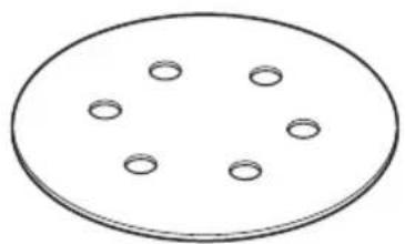
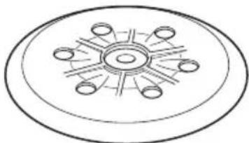
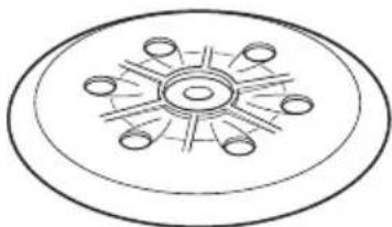
*1: Since the attachment is a hook-and-loop type, the sanding paper can be installed easily by just pressing it onto the pad. When installing the sanding paper, in order to match it to the holes in the pad, gently fold it along the axis of two holes as shown in Fig. 2.
Next, use the holes along the fold as a guide to match
1 the sanding paper and the pad. Finally, press the entire sanding paper uniformly onto the pad.
CAUTION
Do not use accessories with poor adhesion.
*2: When the TurboBoost switch is switched off, the speed can be set at the dial. This is also possible during operation.
Recommended oscillating frequency settings:
Plastic materials 1-2
Metal, Plexiglas®, old coats of paint 3-4
Coarse and fine sanding, polishing, wood 5
The best way to determine the ideal setting is through a practical trial.
Actuate the TurboBoost switch during operation to switch on additional power reserves for maximum material removal rate.
*3: This tool possess two orbit diameter:
- Oscillating circuit high setting (6.2 mm): coarse sanding with high material removal rate.
- Oscillating circuit low setting (2.8 mm): fine sanding, polishing
Changing orbit diameter:
- The plug is disconnected from the receptacle!
- Press in the spindle lock button and hold in place.
- Looking from the side of the sanding paper mounting surface, rotate the support plate until you can hear it engage (Click!).
- Continue holding in the button.
- Continue turning the support plate half a revolution to the next snap-in point (Click).
- Release the spindle lock button.
*4: Use only genuine HiKOKI accessories.
For a complete range of accessories, see www.kokiholdings.com or the main catalogue.
(1) Sanding paper for wood and metal (10 pcs. per pkg.)
(2) Sanding paper for paints and lacquers (10 pcs. per pkg.)
(3) Polishing sponges
(4) Lambs fleece polishing discs
(5) Support plate (soft)
(6) Support plate (Medium-hard): Standard type
(7)Grease
Use a suitable sanding disc to achieve the best possible work results:
- Removal of old paint layers = P40
Pre-sanding of wood = P60, P80 - Finishing of wood = P100, P120
- Sanding of veneers, sealing primer, filler, paint = P180, P240, P320, P400
After installing new sanding paper
Movement of the sander may tend to become unsteady after new sanding paper has been installed, because of the new, coarse grain of the paper. This can be avoided by slightly tilting the sander forward or backward during sanding or polishing. Sander movement will become steady as the sanding paper surface becomes properly abraded.
Operational precautions
CAUTION
- Never run the tool without the sanding paper. You may seriously damage the support plate.
Using the tool with the support plate edge contacting the workpiece may damage the support plate.
NOTE
Looking from above, the support plate rotates clockwise during the loaded operation, but it may rotate counterclockwise during the no-load operation.
MAINTENANCE AND INSPECTION
1. Emptying and cleaning the Dust Bag
If the dust bag contains too much saw dust, dust collection will be affected. Empty the dust bag when it gets full. Remove the dust bag, detach the closure band and dispose of the contents.
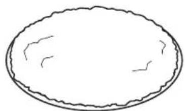
2. Inspecting the sanding paper
Since use of worn-out sanding paper will degrade efficiency and cause possible damage to the pad, replace the sanding paper as soon a excessive abrasion is noted.
3. Replacing a worn support plate
NOTE
If abrasive material (e.g. filled or painted surfaces, etc.) is being sanded, the support plate inevitably wears faster.
- Holding down the support plate, use the hex. bar wrench to unscrew the hex. bolt on the support plate.
Do not loosen the bolt using the spindle lock button.
Doing so may damage the one-way bearing.
- Remove support plate.
- When replace the support plates, always use genuine HiKOKI parts with the number specified in the selecting accessories.
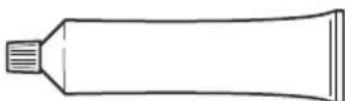
- Apply grease (Code No. 371872) to the side of the brake ring that slides along the support plate.
- Mount support plate and rotate until it engages on carrier disc.
- Insert hex. bolt again and tighten.
4. Replacing support plate brake / braking ring
If the idling speed of the support plate increases in course of time, the braking ring is worn and must be replaced.
NOTE
If abrasive material (e.g. filled or painted surfaces, etc.) is being sanded, the braking ring inevitably wears faster.
- Holding down the support plate, use the hex. bar wrench to unscrew the hex. bolt on the support plate.
Do not loosen the bolt using the spindle lock button. Doing so may damage the one-way bearing.
-
Remove support plate.
-
Replace the old braking ring with the new braking ring (genuine HiKOKI parts), ensuring that the new braking ring is in the same position as the old braking ring. Ensure that the position of the marking on the braking ring is correct.
-
Apply grease (Code No. 371872) to the side of the brake ring that slides along the support plate.
-
Mount support plate and rotate until it engages on carrier disc.
-
Insert hex. bolt again and tighten.
5. Inspecting the mounting screws
Regularly inspect all mounting screws and ensure that they are properly tightened. Should any of the screws be loose, retighten them immediately. Failure to do so could result in serious hazard.
6. Maintenance of the motor
The motor unit winding is the very "heart" of the power tool. Exercise due care to ensure the winding does not become damaged and/or wet with oil or water.
7. Replacing supply cord
If the supply cord of Tool is damaged, the Tool must be returned to HiKOKI Authorized Service Center for the cord to be replaced.
8. Servicing
Consult an authorized Service Agent in the event of power tool failure.
CAUTION
In the operation and maintenance of power tools, the safety regulations and standards prescribed in each country must be observed.
GUARANTEE
We guarantee HiKOKI power tools in accordance with statutory/country specific regulation. This guarantee does not cover defects or damage due to misuse, abuse, or normal wear and tear. In case of complaint, please send the power tool, undismantled, with the GUARANTEE CERTIFICATE found at the end of this Handling instruction, to a HiKOKI Authorized Service Center.
IMPORTANT
Correct connection of the plug
The wires of the main lead are coloured in accordance with the following code:
Blue: Neutral
Brown: — Live
As the colours of the wires in the main lead of this tool may not correspond with the coloured markings identifying the terminals in your plug proceed as follows:
The wire coloured blue must be connected to the terminal marked with the letter N or coloured black. The wire coloured brown must be connected to the terminal marked with the letter L or coloured red. Neither core must be connected to the each terminal.
NOTE:
This requirement is provided according to BRITISH STANDARD 2769:1984.
Therefore, the letter code and colour code may not be applicable to other markets except The United Kingdom.
Information concerning airborne noise and vibration
The measured values were determined according to EN62841 and declared in accordance with ISO 4871.
Measured A-weighted sound power level: 93 dB (A).
Measured A-weighted sound pressure level: 82 dB (A).
Uncertainty K: 3 dB (A).
Wear hearing protection.
Vibration total values (triax vector sum) determined according to EN62841.
Sanding surfaces:
Vibration emission value a_h =
9.0 m/s² (Front handle)
8.3 m/s² (Top handle / Rear Handle)
Uncertainty K = 1.5m / s^2
Polishing:
Vibration emission value a_h = 6.4 m/s^2
Uncertainty K = 1.5m / s^2
The declared vibration total value has been measured in accordance with a standard test method and may be used for comparing one tool with another.
It may also be used in a preliminary assessment of exposure.
WARNING
The vibration emission during actual use of the power tool can differ from the declared total value depending in the ways in which the tool is used.
- Identify safety measures to protect the operator that are based on an estimation of exposure in the actual conditions of use (taking account of all parts of the operating cycle such as the times when the tool is switched off and when it is running idle in addition to the trigger time).
English
NOTE
Due to HiKOKI's continuing program of research and development, the specifi cations herein are subject to change without prior notice.
Vibrationsemissionswert a_h = 9,0 m/s2(Vorderer Griff) 8,3 m/s2(Oberer Griff/Hinterer Griff)
VOORZORGSGMAATREGELEN
9,0 m/s2 (Mango delantero)
8,3 m/s² (Mango superior/mango trasero)
Incertidumbre K = 1,5 m/s2
Pulido:
Valor de emisión de vibración a_h = 6,4 m/s²
Incertidumbre K = 1,5 m/s²
Metal, plexiglas®, gammad malin 3-4
Grov-, finslibning, polering, tae 5
VEDLIKEHOLD OG INSPEKSJON
TENIKE Σ ΠPOEIΔΟΙHΣΕΙΣ AΣΦΑΛΕΙAΣ TOY HΑEKΤΡΙΚΟΥ EΡΑΛΕΙΟΥ

IPOSOXH
AiaBaTe oLeT TnpoEiDOnoiEic aOaAeiac, Tc obnyie, Tc EIOVEc KAI Tc npoBiaypaFec Nou napexovtai eTo nEeKtpko epyaIio.
H m npon twv odnyiw npoei va npokaaleoi nEktpoanxi, npkaia kai/ noepa oopaprpaumatio.
1) Be3onachOCT Ha pa60THOTo MRCTo
a) POndIbPkaHte pa6oTHOTOMrCTO NOppeNo I do6peOCBeTeHO.
Henoppehen nn He do6pe ocbeteHN pa60THn MeCTa ca npednoctabka 3a HnndeHTN.
b) He n3noJ3BaIe eIeKtpnueChn HNCTpyMeHT BBB B3pHBOONacHa CpeDa, npn HaJIyHe Ha 3aNaJIIMN TeUHOCTn, ra3 nn npax.
EneKtpnuecknte HNCTpyMeHTn npoN3BeJdaT NCKPN KOnTO MOraT Da IOBeTaT Da Bb3IJaMeHRAHe.
c) He no3BolraBaIte DocTbI Ha cTpaHnHn IInca n Deua npu pa6oTa c eJeHTpueeCKn HnCTpyMeHTN.
HbHmAHne nBpeMe Ha paOta MoKe da IOBeDe do 3ary6a Na KOHTpoBbpy npoceca.
LcENCeH, NO KOnTo He ca npaBeHN MoNΦnKaUH N CbOTBeTCTBaT Ha KOHTAHTHe HAmAJBaT pNCKa OT eJeKTPuYeCKn ydap.
b) Pn pa6oTa c eIeHTpHuecH NHCtpyMeHTn H36rBaHTe KOHTaKT Ha TAnOTO Cbc 3a3EmHN NOBbpxHOCTn KATO Tpb6n, paHaTOpH n XlaanlHHn.
CbuecTByBa NOBnueH pNCK OT eNeKTpueckn yap, aKO TAnOTO Bu cTaHe Yact OT 3a3eMnteJIHHN KOHTyp.
c) He n3laarTe eIeKtpnuechNte HnCTpyMeHTn Ha BJIaHHeTo Ha BJa r NIN DbHd.
IopanaaHeTo Ha Bnara B eJekTpueechnTe HnCTpyMeHTn NOBnShaBa pNcKa OT eJekTpueechn Yuap.
d) He HapyuabaTe 9eIoCTTa Ha Ka6eJIHTe. HnKora He n3HnIOUbaTe eIeHTpHuYeCKHTe ypeDN, KATO N3DbPnBAte OT Ka6eJa.
Ia3ete Ka6eJIte OT n3TOUHNu Ha TOnnHa, OT Cm3OCHN MaTePnaJn, OcTpN Pb6ObE N NOBUNHH KOMNOHEHTN.
HapaHeHn nn npenIeTeHn Ka6eHn nobuBaBAT pncKa oT eJeKtpnueckn ydap.
e) Horato n3noJ3BaTe eJenTpueechn ypeJ Ha OTHpnto, n3noJ3BaIte YdbJIHHTeJ, NOxOJa3a BbHUnn ycIOBna Ha pa6ota.
H3noJ3BaIe Ka6eI, NOxOJaI 3a BbHJH yCIOBn, KOITo HAMaJIraBa pNcKa OT eJIeKTpUyeCKn yIap.
f) Ako e HaIOHHTeJIHO H3NOJ3BaHeTo Ha eIeHTpueeCNn HNCTpyMeHT BBB BnaHH yCIOBn, H3NOJ3BaIte ypeDn C dIΦepenuHa 3aunTa (RCD) cpeuyyTeuHa. H3noJ3BaHeTO Ha nnΦepeHuaHa 3aunTa haMaJIbRa pUcKa OT eJeHTpueeCNuYdap.
3)JInuHa6e3oNaCHOCT
a)БbTe 6dTeJIHH, BHMMaBaIte B deIcTBnIa cn n H3NoJ3BaIte pa3yMHO eIeHTpNueChIte HHCTpyMeHTn.
He n3noI3BaIte eIeKtpnueeCKn HNCTpyMeHT, HORATO CTE n3MOpeHN, IIN NOB BnIaHHeTo Ha JeHaPcTBeHH cpeCDTa, anHOxOJ IIN ONHaTNI.
BcraKo HeBHMaHne np np paBota c eIeKtpnueckn INHCTpyMeHTN MOHe da DOBepe Do CepNo3HN HapaHbAHn.
b) H3noJ3BaIte JnUHn PpeJna3HN CpeJCTBa. BnHaHn Hocete 3aunTHN OuHa Nm Macka.
3aunTHnTe cpeCTBa, kaTO npaxo3aunTHa MACKa, 3aunTHN ObyBn C yCTOuYBa Ha NtB3raHe NOmETKa, KACKa, nH aHTuDOH, H3NOJ3BaHn CnopeJ yCIOBnTa Ha pa60ta , Ue HAMJrT ONaCHOCTTA OT HapaHBAHe.
c) PpeoTbpaTBAhe Ha clyuayHO BkHIOUbaHe. YBepete ce, ye 6yToHbT 3a CTapr Ha ypeJa e B n3KlIOUeHO NIOJOKeHne, npEn Da CBbpKeTe eJekTpueeCNn HNCTpyMeHT KbM N3TOOHn HA 3axpaHbAne H/nn 6aTeprn, KaHTo n npEn da ro B3emTe nn ppeHacrTe.
IpehaHTo Ha HnctpyMeHTn C npbCT Ha CTapT 6yToHa, Hn Ha npEbnIOuBaTeJI Ha 3axpaHbaHeTO, HOCn ONaCHOCT OT INUdENTn.
d) OTePaHete BcHKn pa6OTHn npHCTaBn, npEtn Da BHIOHTe ypea KbM 3axpaHbHeTo.
Taeuen KIOU HIN INHCTpymeHT, 3a6paBEN B potaunOHn KOMNOHeHTn Ha eJekTpueckn INHCTpymeHT, MoKe Da DOBeDe Do HapaHbaHe.
e) He ce npecaraTe. Ppe3 cJIto BpeMe Tp6Ba Da HMaTe Cta6HnHa onopa N da NODbPkaTe 6aHaHC Ha TJIOTO.
Toba OCHyprBa NO-IO6bP KOHTpOIN Bbpxy eNEKtpnuecknte INHCTpyMeHTn npN HeoayKaBHu CNTuayuH.
f) Hocete noxdxoadno 06leHNo. He hocete npekaheHO shpoHN dpexn nn 6nkyTa. DpbHTe Kocata n dpexnte cn daJeu OT dBHHneNTe ce qactn.
Unpoknte npexn, bnyta n Iblra Koca Morat da 6bdaT3axbaHATN OT NOBNNHHTe KOMNOHEHTN.
g) Ako ca ochrypeHH yctpoHCTBa 3a npncbdeHHBaHe KbM npaxoyIOBHTeHH HHcTaHaun, yBepTe ce, ye ca npabHnHO npncbdeHHeHH.
H3noJ3BaHeTo Ha npaxoyIOBHTeN u cHIOHN MOHe Da HamaJIu Cbbp3aHHTe Cbc 3AmbpCRABaHETO pNCKOBE.
h) He no3BOLIBAHte ONHTHOCTTa BN, npnIO6bTa OT YecTOTO H3NOJ3BaHe Ha HHCTpyMeHTN, da BN Cb3dae cAmOyBcTBHe, 3apaDN KoETO da HrHopnPate npnHcHnTE Ha 6e3oNaCHOCT npn pa6ota c HHCTpyMeHTN.
HeBHMaTeHNO DeIcTBnE MoKe Da DoBePe Do TeKHN HapaHbAHn B paMHTe Ha Yactn OT CekyHdata.
4) EKcNloataaHn npdPbHHHa Ha eJeHTpHueckn HHCTpyMeHTn
a) He hacnBaIte eIeHTpueeCKHTE HcHTpyMeHTN. 3noJ3BaIte NOxOJaEeHTpueeCHN HHCTpyMENT 3a CbOTBETHTE cJIH.
NoxodnayeNeKtpueckn Hcyment Ocnpyra 630nachTo n no-dobpo N3BbPwBaHe Ha pa60THNE DeHOCn npn npedBuDeHnte HOMHaHnnpaMeTpnu.
b) He n3no13BaIte eIeKtpnueckn HNCTpyMeHT, aHO He MoKe Da6bJe BKNIOUeH NIN N3NIOUeHOT CbOTBETHNcTApT 6yTOH NIN NpeBHLIOUBATeJ.
BceKn eNeKtpnueckn HnHCTpymeHT, KOHTo He MoKe Da ce KOHTpOIpna OT npeBkIIOvBaTeJI, e ONaceH N NOJNekn Ha peMOHT.
c) N3HIOUeTe 5eCena Ha HnCTpyMeHTa OT n3TOuHNHa Ha 3axpaHbAe H/INn H3BaTe6BATEpHnnaKet OT nHCTpyMeHTa, aHO ToI NO3BOJRA BaJIaHe, ppeDn Da H3BbPbBaTe HAcTPOHn, npn CmHa Ha npNCTabHn nn npn cbXpaHeHne.
Te3n npedna3Hm Mepn HamaJraBaT pUcKa OT CnyaHNO HeKeHaHO BKNIOuBaHe Ha eJeKtpuuecknH NCHtpymENT.
d) CbXpaHbAaTe Heu3nO3BaHHTe eIeHTpuYeCHn HhCTpyMeHTn DaJeY OT DOCTbN Ha Deua N He No3BOJBAaTe Ha INuca, He3aNo3HaTHn C HauHnHa pa6ota c HhCTpyMeHTte n Te3n HhCTpyKcU, da pa6oTATC Tax.
EneKtpnuecknte HNCTpyMeHTn npedctablaBaT onaCHOCT B pBcTe Ha HeONTHN Iuca.
e) NopdIbpaHae eNtponHcTpymeHTnE n aHcecoapHe. PpOBepBaHte cHTPOBkata H 3aHPenBaHTo Ha NOdBnKHNte qACTn, PpOBepBaHte 3a NOBpeHn qACTn, HONTo MORaT Da ce OTPa3rT Ha pa6Ota T ha eNtPnuechnte HHCTpyMeHTn.AHO yCTaHOBHTe NOBpeHn,OTCPaHete rnpedn da H3noJ3BaTe eNtPnuechnte HHCTpyMeHTn.
MHoro 3IIOJOnyKNe Ce IbJIkaT Ha Nooa NoOpdpBKKHa eNEeKtpnuecknte INHCTpyMeHTN.
f) IopdIbpaHaepeKeIeHTe HcTpymEnTH 3aTOUeHN uHCTN.
PpaBnHNO nOaIbPJaHaHHepeKeHsN HnCTpyMeHTn, C HaToUeHN peKeHsN eLEmeHTn, Ce ynpaBraBaT N KOHTPOINpAT NO-JeCHO.
g) H3noI3BaIte eIeHTpueechn HnHCTpyMeHTn, npHCTaBHN n aHcecoapn, n T.H., cbrIaCHO Te3n HnHCTpyKuNN, KaTO B3eMeTe PpeBnD pa6oTHnte ycIOBnN n BnDa pa6OTn, KOnTo ige ce n3BbPWBat.
H3noI3BaHe Ha eIeKtpnuecknTe HNCTpyMeHTn 3a pa60Tu, pa3IuynH OT Te3H, 3a KOHTo Ca npEdbnDeHN, MoKe Da IIOBede Do NOBnWeH pNCK N ONaCHN CNTyaCnn.
h) Pa3epepbHOXBATHNTE n NOBbpxHOCHTe 3a 3axBaapanec cyxu, qnCTn, 6e3 macno ngpec.
Xlb3raBnte pbKoXBaTHN IN NOBbpxHOCTN 3a 3axBaAaHe He N03BOJIaBt 6e3OnaChata paBoTa n ynpabIeHne Ha NHCTpyMeHTa B HeOyakBaHN CNTyaun.
5) 06cnyHbAHe
a) 06cnykbaheTo Ha eIeKtpnueckHte HNCTpyMeHTn Tp8Ba Da ce N3BbPwBa cMo OT KBAJIHΦHnpuH CEpBN3Hn pa6OTHNu, npH N3NOJ3BaHe HaOpRnHaJIHpe3epBHN qactN.
ToBa ige rapaHTnpa 6e3oNaChocTn npu paBoTa c eIeKtpuecknte HNcTpymEnTu.
BHIMAHNE
He donychaite B30HaTa Ha pa6ota Deca N Bb3pacTHN Xopa. Horato He n3non3BaTe eJeKtpnuecknte HHcTpymENTn, cbxpaHBAiTe rHaJaleu OT DoCTbn Ha Deca N Bb3pacTHN Xopa.
ДОПьЛНITEЛНМЕРКИЗАБЕЗПАСHOCT
- YBepeTe ce, Ye N3TOUHnKbT Ha 3axpaHbaHe, KOTo N3PON3BaTe, OTROBapra Ha N3NCKBaHnTa, NOCOeHN Bbpxy INHBENTapHaTa Ta6JIka.
- YBepete ce, ye cTapt 6yToHbTe bNo3nua I3HJI. Ako 6bJe BHLIOUeH uenceLa KbM KOHTaKaTa, ypeIbT ige 3anOue He da pa6oTH BeHara, pIn 6yToH bNo3nua BHJI., KoETO MOKe Da DOBeDe Do cepno3HN HUNDEHTN.
- 3a da ce npedotbpaTt HnUdENT, UeNceIbT ce H3KIOuBa OT rHe3DTo, npEi Da ce n3BbPWBaT KaKBnTO I da 6nlo Kopekun, KOHBepCnn nn cepBn3HO o6cnykBaHe.
- Pabothoto MraTo Tpa6Ba da e do6pe npoBetpeHO.
5.CneBaaTe HaunohaJIHnTe N3NCKBaHHaMaTePnaHTe, c KOHTO nCKaTe da pa6OTHe. - Korato pa60thaTa 6bIe e OTaJIeueHa OT KOHTaKT 3a 3axpaHbAHe, n3noJ3BaIte yIbJIHKeI C DOCTaTBHa De6eHnHa n NOxOJaI KanaIcTe. YIbJIHKeIeHNrT Ka6e Tp46Ba Da 6bIe Bb3MOKHO HAI-Kbc.
- NocTaBraHe H OTCpaHbAHe Ha TOp6NkAta 3a npax Ppei Da npicTbNITe KbM pa6Ota, npOBepTe KaKbMaTePnI INI NOBbPxHOCT Ue IINΦOBaTe.
Ako NOBbpxHOCTTa, KOTo 6e 6bde 7nHFOBaHa, ce OuaKaBa Da TReHepnpa BpeDeH / TOKcHEn npax (Hanp. OIOBHa NOBbpxHOCT), yBepeTe ce, ye TopoHkaTa Ha CbOTBeTHaTc OUHCTBa7a ChCTema e CBbP3aHa 3dpaBO KbM N3XOda 3a npaxOBN qactu.
OcbEN TOBa, HocTe MaCha, aHo e HaJIuHa. He BnUbaIte u He DOKOCBaIte BpeHInTe/TOKcNHyn npaxOBe, NOJyEHN pRi WlnΦoBaHTo, npaxTa MoKe da 3acTpaun KaKTo BaWeTo co6CTBeHo, TaKa n 3dPaBETO Ha OKOIHTe.
PpaxbOT MaTepeHn KaTo 6oN, CbDbPkaun OIOBO, HAKON BnOBe DbPBeCNHa, MHepaHn MeTaHn MOKe Da 6bDe BpeHn.
OnpeJeIeHN BnOBe npax ca KlaacHnUpaHn KaTo KaHcEporeHHN, KaTO npax OT db6 n 6yK, Oco6eHO B CbYeTaHne C Do6aBKn 3a KOHdNtIOHnpaHe Ha DbPBO (XpOMaT, KOHcepBaHT 3a DbPBO).
MaTePnA, cBdbpHaaun a36ecT, Tpr6Ba da ce n3noJI3Ba caMO OT CneuJaHCTN.
- Практуески пpoцурни работа
O HnKora He cIaIaIte BODa IIN IINΦOBbUHa TeuHocT, KOraTO IINΦOBaTe. TOba MoKe Da IpeDn3BnKa eJeKTpUeCKn ydap.
O HnKora He BkHIOyBaIte IpeBHKIOyBaTeJIa 3a 3axpaHbAHeto, KORATO WLaIeMMAuHnHaTa e B KOHTAKT C NOBbpxHOCTTa, KORTO Ue 6bJe WlNFOBaHa. TOBa e HyxHo, 3a Da CE npEDOTbPaTH NOBpeJa Ha MaTePnAJa. CbUcTo BaHN 3a H3KIOyBaHe Ha 3axpaHbAHeto.
O HNHOFA He npinaraTe npekomepeH aTnck Bbpxyypeda,doKaTo WInoBate. PpeKomepHnrt HaTnckMOKe Da npedn3Bnka npetobapBaHe Ha DBnIaTeJIHaMaJIeH eKcIIIOaTaUNoHEN JHBOT Ha WInoOBbHHnIINCT N HaMaJIeHa eKNaKacHOCT pRn WInofoBaHe nIINoJIIPAhe. - HocTe aHTnfoH npn pa6oTa 3a DbIg n nepnoDn ot BpeMe.
BvCOKHTe HnBa Ha 7ym 3a npOdbJIHNTeJen nepNoD OT BpeMe MoRat Da NOBNIARrHa CnyxBA.
10.MaTePnAJI, KOINTo rHeepnP aT npax nIa napu, KOINTO MORAT Da 6bDaT BpeHn 3a 3dpaBeTo (HaNPmep a36ecT), He TpIbBa Da 6bDaT o6pa6oTBaHn.
11.3aKpeTe DeTaIa CpeUy npnIb3BaHe, HApnpMeP c NOMOuTa Ha 3aTgauN yCTpoNCTBa.
12.RCD (DnΦepeHuaHa eNeKtpo 3aunTa) PpenopbHTeH0e n3no3BaHeTo NO BcRAKO Bpeme Ha yCTPOIcTBO 3a DnΦepeHuaHa eNeKtpo 3aunTa C HOMHaJIeH dNΦepeHuaJIeH TOK OT 30mA.
Былгарский
- B cIeIHnTe cIyUaI IOuNCTeTe TOp6Nkata 3a npax n OTcPaHeTe HAnbJIHO BCNqKna Ipax.
PpaxbT, ocTaHaJI B Top6nKHaTa 3a npax, MoHe Da npedn3BnKa 3anaIbaHe.
-ⅢJINΦOBAHe Ha CTOMaHEn JNCTOBe CJIeD ⅢJINΦOBAuM MaTePnAIn, KaTO HApnPmEp DbPBO
Cleid 3aBbPbBaHe Ha noIinpaHeTo
- Pn n3no3BaHe Ha npedHaTa pbkoBbTaKa ce yBepeTe, Ye n3no3BaTe C HanbIHO 3aTeHrHa H6pa3dEh BnHT.
- Korato zanovbate paobota, ce ybepeTe, ye KopnycBT He e HanykaH.
- He n3xbpIyTe npaxa OT uINFOBaHe B OTKpNT ORbH, TbN KaTO MaTePnAInTe NOd φOpMaTa Ha φINH YactuMoRat Da 6bDat EKcPiO3NBHn.
17.Да He ce n3no3Ba 3a npinloKeHne, pa3nUHO OT npedBnDeha yNoTpe6a. - HnKora He BkIIOUBaIte INHCTpyMeHTa, KORAto e B KOHTaHT C O6pa6OToBAnHЯ DeTaHJI, TOBa MoHe Da DOBeDe Do HapaHЯBaHé Ha Opepato.
CHMBOJIH
PNEpyPENKDAEHNE
N3noJ3BaHn ca cIeHNTe NOKa3HN CmMBOJI 3a MaunHaT. YBepTe ce, ye pa36npate 3HaueHHeTo m npedyn ynotpe6a.
CTAHДAPTHN AHCECOAPN
B DOnbIeHHe KbM OCHOBHnYpeD (1 KOMPJIeKT), KOMPJIeKTBcIbprHa NOCOeHHTe NO-DONY aKCeCoApN.
O IpeHa pBkoXbaTka 1
O 1
Top6nka 3a npax. 1
5MM WecToCTeHnraeueHKnIOU 1
CTaHapTHHe aKcecoapn ca npedMeT Ha npomra 6e3 npedynpexKeHne.
PPIIOXKEHNA
Opy6a 6pb6tka nn 3arlaHdahe Ha nbpBeHn MeTaHn NOBbpxHOCTN.
O PpeBapntHo IINIOBAHe Ha DbpBeHn MeTaHn NOBbpxHOCTN PpeHn 6oAUCBaHe.
CbAJIHe Ha 60J.
CbaJHeHa pBka.
CNEUHKAUH
CneuKauHHe Ha ypea ca nocouHn B Ta6ncaTa Ha cTp.5.
3ABEJIENKA
Blaoropaene Ha HnpeKbchata Ta nporpama 3a HayHOn3cIeDobateLcKa n pa3BoHa DeHOCT Ha HiKOKI, cneuPhiKaunTe, nocouEH TyK, noJleKat Ha npomHa 6e3 npedn3BecTne.
CneI NOCTABRHe Ha HOB WJINΦOBuH JNCT
BnHexHnTa Ha 7aMmaHnHaTMOHe Da 6bDaT HecnpyHn CNeI NOCTABAHTo HA HOB 7mNFOBHe HnCT,3apaHnHOBnTe, rpy6n 3bPHa Ha JnCTa. ToBa MoKe Da ce n36erHe, KaTO JeKO HAKIOHnTe 7MaJFMAuHnHaT a Hanpei nn Ha3aD npn 7mNFOBaHe nn nOInpaHe. DnHexHnTo Ha 7naJFMAuHnHaT a ue Ce cTa6nIn3npa, KOrato NOBpXHoCTTA Ha 7mNFOBbHHn JnCTCe n3HOCh DoCTaTbH0.
PpeDn3HmepKn npn pa6oTa
BHIMAHNE
Hnkora He ncykaTe HnCTpyMeHTa 6e3 uKypKaTa. MoKe cepno3HO da NOBpeDnTE ONOpHaTaNIOya.
O N3nOJ3BaHeTo Ha HNCTpyMeHTa C p6a Ha OnOpHaTa nIOUa, DOKOCBaUa O6pa6oTBaHnA DeTaN, MoKe Da nOBpeDu ONOpHATA NIOUa.
3ABEJIEXHA
TlndaKo OTrope, onOpHaTa nIoOa ce BbptN no YacOBHnKObTa CTpeIka NO Bpeme Ha HATOBapeHaTa ONepaun, HO TMOKe Da Ce BbpTN o6paTHo Ha YacOBHnKObTa CTpeIHa NO Bpeme Ha OnpauTtHa npa3eH XOD.
IODAPbXKA IN IPOBEPHA
1.ИЗпраЗвае И поисвае Ha Top6нчКATA 3a npax Ako Top6нчКATA 3a npax CbДьрka TBБрDE MHOrO CTbproTNH,TOBa ige NOBЛиRe BbPxy Cb6npaHTo Ha npax.IIspa3Hete Top6nKATA,KORATO cHaJIHn. IStBaTe Top6nKATA 3a npax,OTKaHTe JENTa 3a 3aTbapHe INxVBpIeTe CbДьрKaHHeTO.
UHnfoBaHeHaNOBbpxHOCTN:
CTOnHOCT Ha eMmCnHa BnBpaunn a=
9,0 M/ceK2 (npeHa pBkoXbTaHa)
8,3 M/ceK2(ropHa p'bkoxBaTKa/3aHa np'bkoxBaTKa)
HeTOHOC T K = 1,5 M/ceK²
Poinpae:
CTOHOCHT Ha emncn Ha Bnbpauun a h = 6,4 M/ceH
HeToHocT K = 1,5 M/ceK²
DeklapnapHte 06u CToHocTH Ha Bn6paCn Ca H3MepeHN CbIaCHO CTAHApTHHe MeTOHn HA N3NTBaHe H MOrat Da 6bDat N3NOJ3BaHn 3a CpabHeHne MeJdy pa3JIuHHTe INCHTpymEtN.
OcBeH TOBa CTOnHOCTNe MORaT Da ce N3NoJ3BaT 3a npedBapNTeJIHa OueHka.
PDEyPExkDeHNE
O Bn6paunnte no BpeMe Ha npaKTHuecKO n3NoJ3BaHe Ha HNCTpyMeHTa MORaT Da ce pa3JIuHabAT OT NOCoYeHtE 06Uc CTOnHOCTn, B 3aBNCIMoCT OT HaUNHa Ha H3NoJ3BaHe Ha HNCTpyMeHTa.
O NdeHTnHnUnpaHe Ha MepKnte 3a 6e3OnacHocT 3a onepaTopa, Bb3 OCHOBa OceHHa Ba Bb3dEInCTBnETo npn DeNCTBnTEHn YcNoBnHa n3NoI3BaHe (KaTO ce B3emAT npedBnD BCNUH eIeMeHTn OT pa6OTn Hkbl, KaTO nepnoHn Ha BKNIOuBAH n3KlIOUbaHe, KaKTo n pa6oTa Ha npa3Hn O6OpOTn HeNOCpeDCTBeHO npedn CJIed MOMeHTa Ha n3NOJ3BaHe).
3A6EJIeHHHA
Blaorodaepene Ha HenpeKbchata Ta nporpaMa 3a npoybaHe n pa3pa6oTbaHe Ha HiKOK, cneuPhiKaunTe, noocehn Tyk, ca npedMeT Ha npomHa 6e3 npedn3BeCTne.
(Prevod originalnog uputstva)
OPŠTA BEZBEDNOSNA UPOZORENJA ZA ELEKTRICNI ALAT
UPOZORENJE
ODRžAVANJE I PROVERA
1. Prażnjenje i czisćenje kese za prasinu
Ako kesa za prasinu sadrzi previse praseine, to ce uticatina prikuplanje praseine. Ispraznite kesu za prasinu kada se napuni.
Izvadite kesus za prasinu, odvojite traku za zatvaranje i uklonite sadrozaj.
2. Provera brusnog papira
Buduci da ce zbog upotrebe pohabanog brusnog papira efi kasnost biti smanjena i da to moze prouzrokovati kvar podloge, zamenite brusni papir cim primetite habanje.
3. Zamena ishabane ploce nosaça
NAPOMENA
Ako se abrazivni materijal (npr. ispunjene ili obojene povrsine, itd.) brusi, ploca nosaça ce se neminovno brze ishabati.
- Drzejci plochu nosaça na dole, koristite sestougli ključda biste odšrafili sestougli zavrtanj na plochu nosaça.
Nemojte da olabavite zavrtanj koristeci dugme zabravjenje vretena.
To moze da osteti lezaj u Jednom pravcu.
Uklonite nosac ploce.
- Kada zamenjujete nosač ploča, uvek koristite originalne HiKOKI delove sa brojem koji je naveneden pri biranju dodataka.
- Nanesite mazivo (Br. koda 371872) na stranu prstena za kocenje koja klizi duž ploce nosaça.
- Montirajte nosaça ploce i rotirajte ga dok se ne uključi na disku nosaça.
- Ponovo ubacite šestougli zavrtanj i zategnite.
4. Zamena ploce nosaça kočnice/prstena za kočenje Ako se brzina praznog hoda ploce nosaça povecā tokom vremena, prsten za kočenje ce biti ishaban i mora da se zameni.
NAPOMENA
Ako se abrazivni materijal (npr. ispunjene ili obojene povrsine, itd.) brusi, prsten za kocenje ce se neminovno brze ishabati.
- Drzejci plochu nosaça na dole, koristite sestougli ključda biste odśrafili sestougli zavrtanj na plochu nosaça.
Nemojte da olabavite zavrtanj koristeci dugme za zabravlenje vretena.
c)Пдчacpo6OTnABTOMaTHHIM INCTpyMeHTOM He nIpychaiTe Do ce6e diTei npocTo 6aHaOuHx NOINBHTNcH a BaWy po6Oty.
Jkuo Bac BiBolikatmyTb, BN MOKeTe BTPaHTN KOHTpOlb HaiaHCTpyMeHToM.
f) RaHIO He yHHHyTN po60TH y BOJoromy cepeoBnui, KopncTyTEcA dKepeIOM HNBLeHHa i3 npncTpoem 3axncty BiD 3AMnKaHHa Ha 3eMJIIO.
Pnncpi3axnCTyBid3aMnKaHHHa 3emIIO3HnKYe pN3NK ydpay CTPYMOM.
3)Oco6ncta 6e3neka
a) He Btpaayte nIbHocTi, cTeHTe 3a TMM, zo po6nte, i KopnctyItecra 3DopOBHM rIy3dOM niJ vac po60TH ABTOMATUHM IHCTpyMeHTOM.
He npaioHte aBtOMaTHHIM IHCTpyMeHTOM, KOHN Bn BTOMJIeHI a6o 3haxOJNTecr NiI DiIO HapKOTNIIB, ANKOROLIO a6o IIKIB.
Mntb Heybarn nd yac poBOTN ABTOMATUHM IHCTpymeHTOM MOKe CnpuHHTB BaHH Ky TpaBMy.
b) HopnctyItec3ac06amn iHdNbiyaIbHoro 3axnCTy. 3aBHN HopnctyItec 3ac06amn dJa 3axnCTy ouen.
3acobn iHnBidyaIbHoro 3axNCTy, TaKi JPK pecnipatop, YpeBHK i3 npoteKTopAMn, Kaca a6o bepywi, BHKOpNCtahi y BiIDNOBIDHX yMOBax, 3MeHsaTb pn3NK TpaBMyBaHH.
c) 3ano6iraaTe BnnaHOBomy yBIMHHIO. NpeekohaTecra, 0o nepemnau 3haxoNDtbcra B noLoXeHHI «BmKHeHO», nepu HIX NiHIOUHTncra Do DHepeLa HnBLeHHra i/a6o aKymyIaTopa, B3aTcra 3a IHCTpyMeHT a6o nepeHoCHTn Ioro.
Hkuo nepehocn ABTomaTuHi IHcTpMeHTyBIMKHeHmMbO TpMaOnu NaLeCb Ha nepemHa,ue MOKe CTaTn PnHuHO HeaCHO BnnaKy.
d) 3HIMITb 6yDb-8Ki peryIIOUOci KIOUc a6o 6JOKaTOPn, nepw HIX BMKATn IHCTpyMeHT.
Hkuo peryIIOUCh KIOu a6o 6nOkaTOp IINHTn npHKpInHeHM Do YAcTHnH IHCTpyMeHTa, RaKa oBeptaetbCz, ce MoKe cnpNHNHT TpaBMY.
e) He TaHrHtbcra I He nepexnnaTeecra, npauiooun 3 IHCTpyMeHTOM. 3aBKnHaIINHO CTInTe Ha Horax i 36epiraTepHBOBary.
He Hanae Kpaunn KOHTpOb Ha aBOMaTHHm IHCTpyMeHToM y HeCNOiBaHNxCITyauix.
f) Hocitb npabnblhno poobny oJr. He hocitb shnpohn oJr a6o 1OBeJIpHi npHpaCh. Tpmaite CBOE BOLOCCra Ta OJr nOaJI BiD pyXOMnx YactNH. UInpOKn OJr, 1OBeJIpHi npKpacn a6o DoBRE BOLOCC MoHe NOTpaHTN DO pyXOMnx YactNH.
g) RaHy HaABHOCTi E npncTpiI dIa 36npaHHNly, CHOPnCTyItec Hm 3a yMOBn, IIO BIn npaBHbHO nIDHIOueHn I npauoe.
HopnctyBaHH npncTpoem JIJI 36npaHH NITY MOKe 3HN3HTN He6e3NeKN, NOB'ra3aHI i3 HAKONNuEHNM NINy.
h) He Do3BoJHne Yepe3 HABNUK, 3do6yTi BiD Yactoro BHNOpNCtAHN IHcTpymeHTIB, po3Cna6ntncb i irHopyBaTH npHHnN 6e3neHn IHcTpymeHTy.
Heo6epeKHa dI MoKe npu3BecTu Do cepNo3Hnx TpaBM ydoJI cEHyHn.
4) EKnIyatai i DOIa 3a aBTOMaTHHMM IHCTpyMeHTOM
a) He 3actocobyte HaMipHy cnIy do aBTOMaTHUHO IHCtpymeHTa. IINBHKOHHpi3HHx BnIDb po6it ni6bpaTe BiNOBiHi IHCTpymeHTn.
PpaBnIbHo nIiIbpaHn ABTomTuHn IHCTpyMeHT KpaIe BnHOaecpo6Oy i rapaHTyBaTmE 6IbIe 6e3neKn.
b) He Kopnctynteca ABtOMaTHHm IHcTpymeHTOM, Hkso nepemnkaH He npaioe.
Byd-b-kyn aBTOMaTHH nHCTpyMeHT, Kn HEMOHNBO KOHTPOJIOBaTu nepemkaueM, Hebe3neuHM. Ioro cIq nonarOHTN.
c) BiHIOUHTb BUNky BiD dHepeLa HNBEHnra Ta/ a6o BNIMtB anMyIaTOp (AHO BIN BCTABHN) 3 eNEKTPoIHcTpymeHTa, nepw HiK 6yDb-oo perynOBaTH, 3MInHOBaTN npHaADRA 6o 36epiratn eNEKTPoIHcTpymeHT.
Li 3axoH6e3neKTHNHyOTb PN3NK BnnaKOBO yBIMKHHTaBtOMaTHHH IHCTpyMeHT.
d) 36epiraTe ihctpymeHTy Micx, Heoctynhx dIaItei, i He do3BOJnTe IIOAM, He O3HaonmLeHMM i3 aBTOMaTHHMM IHctpymeHTamn i cHMM IHctpKciAmm, HOPHCytBaTNCABTOMaTHHMM IHctpymeHTOM.
ABTomatuHi IHCTpyMeHTn E He6e3neuHmN B pykax HeniIroTOBaHnx KOpNCtByaivB.
e) DOrJaAaTe 3a eIeHTpHnHMn IHCTpyMeHTaM Ta npHaadm. NepeBipnTe, n He 3cyHylnnc a6o He 3aIdaOTb pyxomi YactHH, n He 3Jamalnca Okpeml DeTani, a TaHOXn HE TpanHIOcR RHNXOCb He6aKaHnx 3MiH, Rki MOHYb NoraHO BnInHyTu Ha po6Oy IHCTpyMeHtA. RKnO abTOMaTHnN IHCTpyMeH TNOHODHeHH, Ioro CnId NOnarOHTn nepei NOdaJIbShMM KOpNCTyBaHHAM.
Barato Heuachn BnnaKIB TpannEcbcyepe3 noraHn DoTnA 3a aBtOMaTHNm iHCTpyMeHTam.
f) Buacho YnctbTe i 3aroctpnoTe IHcTpymentn dna piaHHa.
IhctpymEnTH IJI p3aHH, 3a RKMn npabunbHO DOrnaIOb i KI BAcHO NiDToOyIOb, PdWe 3rHaIObC, iX JERWE KOHTPOJIOBAtN.
g) HopncTyuTecn ABTomTuHm IHcTpymeHTOM, anCeCyapamn i HacaDhamn 3riHo uNX ihCTpyKn, BpaxOByoun po6oHi yMOBn Ta 3aBdaHH.
3actocobyte pihi abTomuHHi IHctpmEnTH IJIa piHIN BnDIB POi. HeBIDNObIHicThb IHcTpMeHTA i 3actocvbaHHMOHe CTBOpTN He6e3neHV CNTVaUIO.
h) YtpmmyTe pyuHn 3axBaTHi NOBepxHi cyHMn, qCTHMn, 6e3 MaCTnla Ta 3MaUyBaJbHORo MaTepiany.
CnH3bKi pyuKa Ta nobepxHi IJr TpMaHHa nepeWkoJaKoTb 6e3neHOMy BHKOpvCTaHHIO IHCTpyMeHTa KaHTpOio HaI HmY HeoivkyBaHnx CNTyaicix.
5) 06cIyroByBaHH
a) 06cIyroBbATn BaW aBTOMaTHHm iHCTpyMeHT MoXe IINWE HBAJIΦIKOBaHN TExHIX, 3amIHIOUOn DeTAli NlWe Ha iDeHTNuHi.
Le rapaHTyBaTnme 6e3NeKy aBToMaTHuHOro iHCTpyMeHaTa.
3ACTEPEKHEHH
He niDnyckaHTe do iHCTpyMeHTa dTei HENOBHOCnpaBHX oci6.
Holln iHCTpymEnTom He HOpNcTyIOTbcn, Noro cnId 36epiratn B Micqax, HeDoctynHnx dIra Ditee Ta HenOBHocnpabHHx OCI6.
ДОДАТСВИ ПAPВИЛА БЕЗПЕН
- 豹耶克王汉Tec,0DJIepeJIOHINBHeHH,JHMM B6yTeKOpNCTyBaTnC,BiINOBiDAE BIMoRAM Do JINBHeHH,3a3HaueHm Ha HkJIeui HA KopIyci BInOby.
- NpeekohaiTecra, 0 npemukay HnBHeHHa3haxoHbCBA NOJKeHHI BIMKHEHO.
Hkuo wTenCeIbHy BnIky NiDkIIOUeHO Do MepeKeBooi po3eKn, KOJI npemKau XHBLeHn 3hAxOuTbcB nolooHenHi YBMK., ToDi IHCTpymeHT HeraiHo Noue He npaObaTu, a ue MoKe npn3BeCTn Do HeuacHOro BnPaNDKy. - 306 3anobirn HeuacnBnnaDkam, nepeBnKoHaHHaM 6yNb-RAxN xpeRyIHOBaHb, 3MiHOBaHb a6o 06CnyROByBaHHcIiO6OB'ra3HOBO BnMaTH uTeNCJIbHy BNky 3 MepeKeBooi po3eTKn.
-
Poboe Micue Mae dope npoBtPBOBaTHCA
5.ДоТРИМУTEcB HaцioHaJIbHIN BIMor Do MaTePiaJIIB,3 RAHMn 36IpaETecr npaUOBaTN. -
HoJn po6o7a NOBepxH3hAxOHTbc8 DaIeKO BiD JHepeJa HINBLeHH, KOpNCyTEc8 NODBHyBaem DOCTaTHbOi TOBUnHN i HOMHaJIbHOi NOTyXHOCtI. IIOOBKByBauchm6Ty HAcKiJbKn KOpOTKHM, HAcTIbKn IpaKTunHM.
-
YctaHOBLeHH Ta 3HATT MaIka DnI NnIy Iepw HIX NOatn Opeaio WlifyBaHH, nepeBipTe NOBepxHIO MATEpiaIy, RkN 3bnpaCTecb WlifyBaTH.
HkuoB npoueci wliybaHH noBepxHi ouikyeTbcra YTbOpeHH uIDNBOrTOKcHOro nnly (HaPnKlaI, WliybaHH fap6oBaHO iOBepxHi npOBdy), nepekoahTeCBA TOMy, 00 MiOu DNny aBO HaJeKHy CNTeMy-nIOBLOBIOBau UINbHO npneDHaHO DO OTbOpy DIA BIDBOy Nl.
Ha daTOK do BCbOro, HadiHbTe npOTnIIOBn pecnipatop.
He BdxhaTe i He TopkaTecra WkIdnHBOrToKCHNHO nny, yTBOpEbCBAe3yIbTaTI wliyBaJIbHOI onepaui, mIO MoKe cTAHOBHTn He6e3neky dJa BlnacHOrO 3doPob'ra Ta ocio, 0o 3haxoJbCnopA.
Пил BiД MaTePiaJIb,ТанхЯК phap6a,ЮMiCTnTb CBnHeIcB,ДeякВИДn DepeBa,MIHepaII N MeTaI,MOKe 6yTHuKIDINBIM.
DeKi BnI NIIy KlaacNphiKyIObCra KKaHcpePOReHHI, HApNIKIAI, NII dy6a Ta 6yka, Oco6lnBO B NoeHaHHI 3 Do6abKaMn DnKoHNuioBaHHA DepeBnH (XpOMaT, KOHcEpBaHT dIg DepeBnH).
MaTepiAnu, uO MicrTb a36ecT, MaOTb o6pO6nTu TInbKn faxiBci.
- Kopinipnabnla eKcnnyataa
OПд уac wIiФуВангЯ HabKdauHm panepom HikOnn He BxNBAite Body a6o WlifyBaIbHy piDInHy. Lc MoKe np3BecTn Do ypaKeHHRe eNeKTpUHm CTPymOM.
O Hikon He BMKaHTe nepemKauy KINBHeHH (noJooHenn YBIMK.), KOJIu 7IiOyBaIbHa MaunHa KOHTaKTye 3 NOBepxHeo 7IiOyBaHn. Lc Heo6xIdHo, 06 3an06irtn noWKoDKeHHIO MaTepiany. C1i DjTn aHaIorIHHO, KOJI N BmIKaTe JINBLeHHa (noJooHenn BIMK.).
HE 3actocobyTe HaMipHn TnCK Do WlifyBaIbHOI MaunHn NiJ Yac WlifyBaHHa. HaMipHn TnCK MOKe BHKInKaTH NepeBaHTaKHeHHa DBNyHa, 3MeHNeHHa TepmiHy CnyH6n HauDaHOro Nanepy N 3HNKeHHa efeKTnBHOCTi WlifyBaHHa a6o nolipyBaHHa.
- BnKOpNCToBnyTe 3acO6n IJRA 3axNCTy oprAhIB cIvy, KOJI npaioTe npOTAROM 3HaUHIN npOMiKKIB yacy. IJI BnCOKOro pIBH pyMy npOTAROM TpNBALIO rpeIOdy MOKe npN3BeCTn DO noripWeHHraClyx.
10.3a6opohreTbC O6pOJIaHn MaTepiAa, npn o6pOci Rknx yTBOpIOJcR nn a6o napn, kI MoKHTb 6yTH WkiINBIMn Ira 3dOpOB' (HaPnKlaD, a36ecT).
11.3aKpinitb Detanb,ky 6yndeTe o6pOblTn,io6 BOHa He KOB3aJa, HApNklaD, 3a DOnOMoTO 3aTnCKHnx npicTpoIB.
CTAHДAPTHI AHCECYAPN
Okpim ochoBHoro npncTroIO (1 npncTpiI,do KOMnJIeKTy BXoAraTb aKceCyapN,pePik IaIKx NpeDCTaBHeHO HnKHe.
O Ipeednpykota 1
O HaJaunn nanip (P120) 1
Miokdny.. 1
O UeTnIpaHHN KJIIOU 5 MM 1
HOMnIeK TcAHaapTHOrO nplaDn MOHe 6yTN 3MiHeH N6e3 nonepdKeHH.
OBJACTI 3ACTOCYBAHH
O YopHOBa a6o YnCTOBA o6p6Ka DepeB'AHnx Bnpo6i MeTaJIeBNX NOBepxOHb.
O Nonepedhe wliyBaHHa DepeB'HNb Bnpo6iB i MeTaJIeBNX NOBepxOHb NpeD fap6yBaHHaM.
O BndaJIeHHaIap6n.
O BndaIeHnIipKi.
TEXHIUHIXAPARTEPNUCTKIN
TexhiHx xapaKTepeNCTnKn DaHOro npncTpoH HabeJeHO B Ta6nuiHa cTOp.5.
#
Yepe3 noctiHi DocJIigKeHHH i po3BnTOK, kI 3diNCHIOKOMnaHia HiKOKI, TexHIcHIXapaKTepnCTnKIMOHyTB 3MIHOBaTnC6e3 nonepeJkeHH.
HA3Bn KOMNOHEHTIB (Pnc. 1-Pnc. 12)
He BnKOpNCToByTe aKcecyapn 3 noraHm npJraHHM.
*2: KOnn nepemukau Typ6opexHmMy BmKHeHO, WbNdkicTb MOxHa BcTaHOBuTH 3a DonomoroIO peryIaTopa. Lc TaKoK MoXHa poBHTn iD Yac po6OTn.
PekomeHIOBahiHaJIaHTyBaHHaCTOTN KOINBaHb: INaCTmacn 1-2
Metan, Plexiglas (oprcnlo), cTapi wapn fap6n.....3-4
Tpy6o-Ta dpi6Ho3epHnCTe wliyBaHHn, noipyBaHHn, depeBnHa .5
Kpaun cnocio BN3NaHTn iedeaJIbHe HaIaSTyBaHHe BInpO6yBaHHHa npakTnCi.
AKNBByTe nepemHKaT Typ6opeKmMy niJ cac po60TH, 06b yBIMKHyTN DoaTHKOBI pe3epBN NOTyHXOCTI dJH 3a6e3neueHH MaKcImaJIbHOI WBNIOCTI 3HimaHH MaTepiany.
3aTepeKeHHnPiJ Yac eHcNlyatauii OBEPEKHO
O Hikoln He npaioHe iHCTpyMeHToM 6e3 HaKaHOro nanepy. Bn moKeTe cepNo3Ho noWKoDHTn onOpHy nlaactuhy.
3actocybaHHIhCTpyMeHTa, KOJI KpaIIKa onopHOI pIaTINH TopKaETbC8 o6pO6IOBaHOro MaTePiaIy, MOKe NOnIKODHTN ONOpHy PIACTHHy.
IPMHMITKA
HnBnAChc 3Bepxv, onOpHa nlaCTHa o6epTaetbcra 3a roDHHNKOBIO CTpiKIOI niJ vac po60Tu 3 HabaHTaKeHHAM, aJe BOHa MOKe o6epTaTcNpOTn rOoHHNKOBOI CTpiKNPiJ vac po60Tu 6e3 HabaHTaKeHHJ.
TEXHICHE OBCJYROBYAHHH TA NEPEBIPHA
1. BnBaHTaXeHHa Ta YnCTHa MiHa dIy nHly
HkuoMiok dIy nIy MICTb 3abarato TnpC, ce 6yde uKOHTN 36bpahnIO nIy. KOni Miok dIy nIy 3aONBHtCB, BNCINTe 3 HbOTo CMITT.
3HIMITb MiOK dIa nnly, BiD'eHaIte 3aKpNBHy CTpiKy Ta BndaJIb BMICT.
2. IpeBipka HauHdauHoro nanepy
OckilbKn BnKOpncTaHH 3HOWeHOr HaJdaUHOro nanepy 3MeHwye eFeHTnBHiCTb 6p06Kn MoHe npN3BeCTn DO NOWKODKeHH PPOHaJaKn, 3aMiHIOHTe HaJdaHn nnip, Ra TlBKn NOMiTte HaMIPHN a6pa3NBn 3Hoc.
3. 3aMiHa 3HoWeHOi ONOpHOI NlaCTHNIPIIMITHA
Jkuo uifyubc a6pa3nBmi Maepiaan (HapnKla, 3aunakbOaHi a6o nofap6oBaHi nobepxHi Toio), ONOPHa PnactnHa HEmHyue 3HOuyETbcr SwBnDne.
- UtpmyoOnOpHy nlaCTnHy, BnKOpNCToByTe WeCTnrgpanHnn KIOU, Oo6 BNkpyTHT 60NT i3 WeCTnrgpanHOI rOIOBkoHa OnOpHi nlaCTnHi.
He nocla6nIe 6oJIr 3a donomoroIO KhoHKn 3aTnCKy nnHdJI.
Lc MoKe npBecTn Do NOnKoJKeHHa OndHobiHoro NiDunHnKa. - 3HIMITb onopHy nlaCTnHy.
Koln 3amHIOeTe onOpHi nlaCTHHN, 3aBHN BHKOPNCOByIte opnirhaJIbHI 3anachi YactHH HiKOKI 3 HomepaMn, yka3aHIMn Ha Bn6paHOMy DoaTHOBOM npnaJad.
HaHecitbMaCTnIO (KoD No 371872) Ha6ikraIbMIBHO KJIbca, JIKN KOB3aE B3DOBx ONOPHOI nlaCTHH. - YctahOBiBbONOpHy nlaactHy Ta nobepTaIte II, NOKU BOHa He BBIIne B KOHTaKT 3 HecyHIM DNCKOM.
3HOBy BCTaBTe 6oJIT i3 ueCTnRpaHHOIO rIoOBHOIO Ta 3aTAYHtB Horo.
4. 3aima ralbma onophoi nlaactHHrAibmbHoro Kilbua
Hkuo yactota 06epTaHH xolocTOO xOdy onopHOI nactHH 36ilbWeyTbcn npotrom acy, raBmIBHe Kibue 3HOwyeTbcra Ta noro Tpe6a 3amHHTN.
NPMMITHA
Kuio 1iYIObC a6pa3nBHi MaTepiAn (HapnKlaI, 3aunaklbObaHI a6o noap6oBaHI NOBepxHi ToO), raMbIMBe KJIbue He HEmHyue 3HOUyETbCra WBNIDhe.
UtpmmyoOnOHTNY,BnKOpNCOTBynte
WeCTurpanHnn KIOU,OOBuKpyTNT 60NT i3
WeCTurpanHOI ROLOBOHO Ha ONOPHI IaCTNIi.
He nocla6JIaTe 60NT 3a DOnOMOIO KHOHN 3aTNCKy
WinnDieJ.
Le MoKe npBeCTn Do NtIKoDKeHHa OHObIHORO
PiDuHNHa.
- 3HIMITb onOpHy nlaCTnHy.
3amHITbCTape raIbMIBHe KJIbue Ha HOBe (opnIHaJIbHi 3anachi yactHH HiKOKI), yneBHITbcra, lo HOBe raIbMIBHe KJIbue 3hAxOINTBcRA B TOMy JN NOIOKeHHI, IIO NCTape raJIbMIBHe KJIbue. NepekoHaTecra, IIO NOIOKeHHaNO3HaUKN Ha raJIbMIBHOMy KJIbci e npaBnblHM.
HaheciMbMaTnlo(KoD No 371872)Ha6ikraIbmbHoro KJIb4a,RAHKOB3ae B3doBx ONOPHOI nlaCTHH.
- YctaHObITb ONOPHy nlaactHy Ta NOBepTaIte II, NOKH BOHa He BBiJe B KOHTaKT 3 HecyHM DNCKOM.
3HOBy BCTaBTe 6oIIT i3 WeCTnRpaHHOIO rIoOBKOIO Ta 3aTARHITb Horo.
5. Orna KpinnIbHnx rBHTiB
PeryIpaHOr OraJaTe Bci KpInnIbHi rBHTn i nepeBiprNte ix HaleKHy 3aTJkHy. Pnp OcIa6JIeHHi 6yDb-RAkNX rBHTiB HeraHOb 3aTARHtB ix 3HOBy. HeBHKoHaHHa ciEi BmOrn MoKe npn3BeCTn Do cepNo3HoI He6e3neKn.
6. Texhiyhe 06cnyrobyBaHHa DBnryHa
TolOBHIM KOMHOHEHTOM eEeKtpoiHcTpymeHTy o6MOTHa eEeKtpoDbnHyHa. PnpdiJrHe halekHy yBaIy TOMy, 06o6MOTHy He 6yNo nOwkoJxHeo Ta/a6o Do Hei He NOTpanNIO MaCTnlo a6o Boga.
7. 3aMiHa WHypa HnBHeHHA
Hkuo NooKOHeHO Hyp HNBHeHH eNkTpoiHcTpymeHTa, eNkTpoiHcTpymeHT Heo6xIDHO NOBepHyTN B yNOBHOaKeHH cepBicHN ceHTp HiKOKI dJr 3amHn shypa.
8.06cIyroByBaHHa
Ypa3i HecnpabHocti eIeKtpoiHCTpyMeHTa 3BepHITbc4
do yNOBHOBaHeHOro npedctaBHnKa cepBICHORO
06cnyrobyBaHHra.
06EPEXHO
IiHacpo6oTnIdorJyCII6paTnDo ybaru MiccEbi HOpMn i cTaHapTn.
TAPAHTI
Komnai rapaHTye, 0eEKeTpoHCTpyMeHT HiKOKI BuroTOBHeo 3riDHO 3 yctaHOBJEHMI MicueBMn peyIIOUOHM HOpMaMn. Lra rapaTir He po3NOBCOJHyETbCn Ha deFeKTn a6o N0WKOJHeHHape3 3IOBHNBaHH, HenpaBnJIbHe KOpNCYBaHH a6o 3BnuAne CnpauOBaHH. JaKIO MaTe ckapn, 6yNbJaCKa, HadiuITb eEeKToPiHCTpyMeHT, He po3bnpaOuN Ioro, 3 TAPAHTIINHM CEPTNIKHATOM, knn 3haxOntbcB KInci daHOi IHcTpkyii 3 BNkOpncTaHH, Do ynoBHObaJeHOro cepBichoro ceHTpy HiKOKI.
Ihopmaqia npo wym ta Bi6paiciu
BmipHi BeJnHn BN3haeHi 3riHo EN62841 i BN3HaHO TaKIMN, 0o BiIIOBIAIOb ISO 4871.
BmipraHn piBeHb nOtJxHocTi 3Byky B cnIBiDHOweHHI A: 93 d5 (A)
BmipraHn pBeHb TnCKy 3ByKy B cnIBBiJHOWeHHi A: 82D5(A)
Poxn6ka K:3d5(A).
Hocitb npictpi 3axncty oprahib cyxy.
Nobhe 3naeHnB Bi6pauii (TpnaKciaIbHy BeKTOpHy cyMy) Bn3NaueHo 3riDnO 3 EN62841.
LliyBaHHnIOBepxohb
3HaYeHHBibpauii a=h
b) He nCnoJb3yIte 3JeKTHpOHCTpyMeHTbI BO B3pbIOoNacHbIX OKpyHaIOuNX ycIOBnX, HApPIMep, B HenocpeDCTBeHHo6n3OCTn ORHeONaChbIX HnDKoCTeR, ROpOuHX Ra3OB NnI JERHOBOcPnAmEHaIOUeCnbln.
3NeKTPoHCTpyMeHTbI npOPOJdaIOTHUCPbI, KOTOpbie MOrYT BOCIIaMEHHTb IIbIb IIN HcnapeHn.
c)ДерхиTe DeTei Ha6JIIOdaIOUxHa 6e3OanachOM paCCToHNN BO BpeMЯ 3KcIpyaTuIN 3JIeHTpOHNCHTpymEHTa.
OTBLeueHHe BHMaHm MOKeT CTaTB JnBac npuHOn Notepn ynpabHeHn.
2) 3JIeKtpo6e3onacHocTb
a) CeTeBbI BnHn 3JIeHTponHCTpyMeHTOB DOJHHbI COOTBcTcBOBaTb CeTeBOI PO3eTHe. HNHorda He MoINΦuNpyIe TtEnCeIbHyIO BnIKy HnHOHM 6pa3OM. He NcNoJb3yIte HnHaKHe aAnTpHbIe nepExoHNH C 3a3EmJIeHHbIMN (3AMKHyTBIMN Ha 3emJIIO) 3JIeHTponHCTpyMeHTAmn. HEmOINΦuNPOBaHHbIe 7tENCeJIbHbIE BnIKN I COOTBcTcBYIOUe IM CeTeBbIe PO3ETKN yMeHbWAT ONaCHOCTb NOPaKeHn 3JIeKTpNUeCKM TOKOM.
b) He npnacaiTecb TeIOM K 3a3emJeeHHbIM NOBepxHocTAM, HApHmep, K Tpy6oNpOBoaM, paHaTopaM, kyXOHbIM nHTam XOJODINbHHaM.
EcnBaWe TeNo CoPnKoCHcTc C 3a3eMJIeHHbIMN NOBepXHOCTaMn, BO3paTe TOnaCHOCTb NopaKeHNA 3JIeHTpueeCKm TOKOM.
c) He noDBepraTe 3JeHTponHCTpyMeHTbI DeiCTBnIO BODblnn BnaH.
Pn nonaHn B0bB 3JeKtpOHCTpyMeHT BO3pactet OnaCHOCTb NopaeHn 3JeKtpueeCKM TOKOM.
d) PpaBnIbHO 6paauTecb co shypom. HkoIa He nepeHocTe 3JeHTponHCTpyMeHT, B3AIBuNcB 3a Whyp, He TAHIne 3a Whyp n He depraTe 3a Whyp c ceJbIO OTCOeHNHeHHa 3JeKTHPOUNHCTpyMeHTa OT CTeBOI PO3ETNI. PacNoIarai Te Whyp nOdaJIbWe OT NcTOUHNHOB TEIIa, HeFTenpoDyHTOB, PpeMeTOB C OCTpbIMN KpOMHAMN IN DBNkUxXcR DeTaJIeN.
Повржденийи Или 3аутаньie 小HypbI yBeINuHBaIO T ONaCHOCTb NopaKeHnJ 3JIeKTPNueCKHM TOKOM.
e) Ppn 3Hcnpnyataun 3JeHTpOHnCTpyMeHTa BHe NOMeueHn, HcnoJb3yIte ydInHnTeJbHbI WHyp, npedHa3NaeeHHbI dJa HcNoJIb3OBaHnBHe NOMeueHn.
IcnoB3OBAHne Uhpya, npedHa3HaueHHoro IpaobTbI BHe NOMEeHN, yMeHbWIT OnaCHOCTbNopaeHn 3JIeKTPnueckn TOMOM.
f) Ppn 3Kcnnyataunn 3JeKtpoHnCtpymeHTa BO BnaXHo n Cpege HcNoIb3ynte yCTpoNCTBO 3auntHO rOTHIOUCHENH NCTOHNHa NTaHH.
IcnoB3OBAHn yCTPOINCTBa 3aunTHORO OTKIOUeHn yMeHbIHT ONACHOCTb NopaxHeHn 3JIeKTPNueeCKHM TOKOM.
3)JInuHa6e3OnaHocOb
a) BybTe rOToBbI K HeoHnHaHHbIM CnTyauNRM, BHMaTeJbHO CJIeNTe 3a CBOHM N DeiCTBnRMn pyKOBODCTByTEcB 3dpaBBIM CmblON pnp 3KnnyatauN 3JeHTpOHnHCTpyMeHTa.
He nCnoIb3yIte 3JeKTHpOHHCTpyMeHT, KOrda Bbl yCTaII HnH HaxoIITecb NOD BnHnHEm HApKOTnHOB, aIKOIOJIa IIN JeHapCTBeHHbIX npenapaTOB.
MrHOBeHHa NOTep BHNMaHb BO BpEm 3KcNlyatau 3JIeKTPOHCTpyMeHTOB MOHeT npBecTu K cepbe3HO TpaBMe.
b) HcnoIb3yIte HnHnBnDyaIbHbIe cpeCTBa 3aunTbI. Bcerda hadeBaIte cpeIcTba 3auNTbI rna3.
CpeCTBa 3aunTbI, TaHne KaN npOTNBONBJeBOI peCNIPAToP, 3aunTHaO6yBc HecKoJb3KoI NOoWBOi, 3aunTHbI WlEM-KACA INI CpeCTBa 3aunTbIOprAHOB CnyxA, IcNoJIb3yEmBe B COOTBetCTByUxnx YcNOBnAIX, CHINAT YHCLO TpaBM.
c) H36eraTe HenpeDhamepeHHoro BKNIOUeHnA DBNrataTeJIy6eHTecbBTOM,TOBbIKIIOuOaTeJIb HAXODNTcB NOLOHEHN BBIKIIOUeHn NEpei NOHMaHHeM, nepeHOCho HnN NOCDoeHNHeHem K ceteBOJ po3eTHe n/HnN NOPTaTHBHom 6aTapeHOMY NCTOCHNY NHTAHIA.
Ipehocka 3eKTPoHCTpyMeHTOB, KOrda Bbl depKHTe NaLeu Ha BbIKIOUaTeNe, NIN NOcOeHNHeHne 3eKTPoHCTpyMeHTOB K CeTEBOI PO3eTke, KOrda BbIKIOUaTeJIb HaxODNTCB INoHOHeHn BHIOUeHn, PnIBoNT K HeCuaCTHBIM CnyaM.
d) ChHmnte BCE perylnpoBOHbIe HnraeyHbIe KJIouN nepeB BKHIOUcEHHeM 3JeKTHpOHnHCTpyMeHTa.
FaeHbI INIpeRyINPOBOHyB KJIIOU, OCTaJIeHHbI INPKpeIeHHbIM K BpaJauOJcNc JETaJI N 3JIeKTPoIHCTpymEHTA, MOKeT PnIBecTH N IOLyehHIO TpaBMbl.
e) He TepaTe yctOuHBOCTb. Bce BpemnmeTToCHy onOpbl n coXpaHnTe paBHOBeChe.
TO NOMOKeI LyuWe ynpaBnTb 3NeKtponHCTpyMeHTOM B HEnpeBvDeyHHbIX CNTyaUx.
f) OdeBaItecb HaJIeHaaUM 6pa3OM. He HadeBaIte npocToPHyO ODeHdy HnIOBeJIInpHbIe n3dEINr. DePKeHTe Baun BOLOcB IN ODeHdy KaH MOHHO daJIbUe OT DBNHyUxCnYacteJ.
PpocToPha OeKa,IOBeIuHbIe N3JeNn IIN DInHHbIE BOIOcB MoYr NOnAcTb B DnKHyUneCyaCTn.
g) Ecn npedymotpehbl yctpoicTba dI npncoeHHeHn npncnoc6leHn dIOTbOa n c6opa nbIIN, y6eHntecb B TOM, YTO OHn npncoeHHeHb NcnoJIb3yIOTc HAdJeHaunm 06pa30M.
HcnoB3OBAHHe daHHbIX ycTPOIcTB MOKeT yMeHbWHTb ONaCHOCTH, CBraHHbIE C nbJIbIO.
h) He no3BoJnTe 03HaKOMJIeHHo, NOJyHeHHOMBy pe3yIbTaTe YAcTOrO HcNoJIb3OBAHHaHnHCTpyMeHTOB, ycBInNTb BaWy 6dnteJIbHOCTb n OCTOpOHIOCTb n HrHopNpOBaTb npNHcINbl6e3OnachOH 3KnlyaTaUHnHCTpyMeHTa.
HeocTopoKHOe DeHCTBNE MOKe TcTaT npuHHOc cepbe3HO TpaBMbl BdoJI NCEHyNDbI.
4) 3Hcnpnyataunn H o6cnyHHBaHne 3JIeHTpOHHCtpymeHTOB
a) He neperpykaTe 3JeKTPoHcTpymeHT. HcnoIb3yIte HaJNeJaUd Ira BaWero npHMHeHHa 3JeKTPoHcTpymeHT.
HaJIeJaHn 3JIeKtPOnHCTpyMeHT 6yJeT BbINOLHrTa paOTo IyUWe H JaEHHHee B TOM peKHMpeoTo, Ha KOTOpBn OH paccuHaH.
b) He nCnoB3yIe 3JeKTHpOHHCTpyMeHT C HeHCnpaBHBiM BbIKJIIOHaTeJEM, ecJN C erO NOMOuBIO HeIb3A 6yDet BKHIOUHTb H BBIKIOUHTb HHCTpyMeHT.
KaHdbI 3eHTponHCTpyMeH, KOTOpbIM HeIb3a
ynpabTb C NOMOsbIO BbIKNoCuTeN, BydET
npEdCTabTb OnaCHOctb, Iero BydET Heo6xOuMo
OTpEMOHTPOBaTb.
c) OToeHNHte 1TeNceIbHyIO BnHry OT nCToUHnHa NITaHn H/INu ydaJIHTe 6aTapeHHb 6JOK, eCIn OH CbeMHbI, OT 3LeKTPOnHCTpyMeHTa nepe Haayalom BbINOJIHeHHa KaHX-Jn6o peRyIHpOBOH, nepecMehn npHaIeHHocTe INn nepeXpaHeHHem 3JeHTpOHHCTpyMeHTOB.
Takne npoФнаKTnuecKne Мepbl 6e3onacHocTnyMehbwaT onaCHOCTb HnpeHaMepeHHoroBHLIOUeHnI DBnraTeJIg 3JIeKTPOnHCTpyMeHTa.
d) XpaHnte HeNCNoIb3yEmbIe 3JIeKTHPOUHCTpyMeHTbIBHeIOCTyINHomdJIaTeMecTe, H He pa3peWaaTe IIOJAM, He yMeIOUIMo6paataBcA C 3JIeKTHPOUHCTpyMeHTOM nHn He N3yUHBWM DaHHoe pyHOBOdCTBO, pa6OtaTb c 3JIeKTHPOUHCTpyMeHTOM.
3NeKtpOnHCTpyMeHTbI npedCTaBIAOT onaCHOCTb B pykax HenoTROTOBHeHHbIX NOJIb3OBATeNei.
e) CoepHnTe 3JeKTPoHnCTpyMeHTbl n npHaJleXHOCTB HcnpaBHOM COCTOHH. PpOBepbTe, HeT nn HecooCHOCTH nn 3aeDaHHyUxxCsYacTei, NOBpeHHDeHHA Detalee nn KaHoro-Jn60 dpYrTOO 6cToTBeLbCTBa, HOtOpoe MOHeT NOBJIaTB Ha FyHKuONHOPOBaHne 3JeKTPoHnCTpyMeHTOB. Pn HAnuHN NOBpeHHDeHH OTPeMOHTpyHTe 3JeKTPoHnCTpyMeHT nepeedero 3KnlyatauNe. Bolbwoe KOJIueCTBO HeCuaCTbIX CnyaEB CB3aHO C IIOXIM OBCLyHBAHNEM 3JeKTPoHnCTpyMeHTOB.
f) CopeHnTe peHnyuine HNCTpyMeHTbIO octpo 3aTOeHHbIMN NCHTBIMN.
HaJIeKaUH M O6pa3OM COepeKaUHecB HcnpaBHocTH peKyuIe NHCtpyMeHTbC OCTpbIMn peKyuIMN KpOMKaMn 6dyT MeHbWe 3aeJaT n 6dyT IerYe B ynpabLeHIn.
g) HcnoJb3ynte 3JeKTPoHnCTpyMeHT, npHaJleJXHOCTN, HacaJH N T.I. B COOTBETCTBn C DaHHbIM pyHOBOdCTBOM, npHHMaB BO BHMaHHe ycIOBnI O6bEm BBINOJIHReMoPa6Otbl.
HcnoIb3OBAHHe 3eKtpoHCTpyMeHTa IyBbIOJIHeHnpa6OT He IO pRmOMy Ha3HaueHIO MoKeT npUBeCTN K ONaCHOn CHTyaCIN.
h) POndepHnBaIte pyuHn IOBepxHOCTn 3aXBaTa cyXHM, YNCTbIMn HHe3aRpa3HeHHbIMn MaclOM n Cma3KoN.
CkOJIb3KHe pyuHn H NOBepxHOCTn 3aXbTa He IO3BOJIAIOT 6e30NaCHO UnpaBnTb INHCTpyMeHTOM N KOHTPOINPOBaTb EOr B HEoKnDaHHbIX CNTyaunX.
5)O6cnyHnBaHne
a) 06cnyHbAHne BaWero 3JeHTpOHcTpyMeHa TdoJIHHo BblIOJIHrTBcR HBAIIHnIuNpOBAHHbIM npedCTaBHTeJEM peMOHTHO C LyK6bl C HCNOJIb3OBaHNEM TOlbKO NDeHTNUHbIX 3anachbIX YacteJ.
3To 06ecnent coxpaHHocTb n 6e3onacHOCTb 3JeKTPoHnHcTpymEnTa.
MEPbI INPEOCTOPOXHOCTN
DepKHTe NOdaJIbIe OT DeTeH N HEMOuNbIX IIOJe.
Ecnn HNCTpyMeHbI He HCNoB3yIOTCn, HX CneNyET XpaHNTb B HeOCTyHOM DJIa DeTe N HEMoUhbIX IIOeMecTe.
ДОПОЛНТЕЛьнtie YHA3AHNЯ ПО OБECПЕHENIO BE3OПACHOCTN
- PpocJeHte 3a Tem, TTO6bI HcNoJIb3yEmbI NCTOCHK 3JIeKTPoNITAHIN COOTBETCTBOBaI Tpe6OBaHNM K ICTOCHNK 3JIeKTPoNITAHIN, yKa3aHHbIM Ha TINOBOI Ta6NIuKe H3dJIInJ.
- Yeudntecb B TOM, YTO nepeKIOHcATEJIb HaxoHTcB NIOJOKeHN «BbIKI.»
EcIn Bbl BCTaBlaeTe WtEnceIb B po3eTky, a nepeKlIOHataIb HaxoINTCB B NIOLOKeHN «BKn.》, INCTpyMeHT HEmdJIeHHO 3apa6OtaET,TO MOJET CTaTB npuHHOH cepbE3HO TpaBMbl.
- YTo6bI npedotBpaTHTb HeCuaCTHbIe clyuAn, BbIHMaIte wTeNCEJIbHyIO BNILHy I3 po3ETKn, IpEHNDe. YEM BBINOJHrTb IIO6bIe perylnpOBKn, IN3MeHeHn INN 06cIyKINBaHne.
4.ObecneyTe XopoWtu BOHTnlau npa6oey 30HbI. - Co6IIOJaTe DeHCTByIOUHe HaUNoHaJIbHbIe npedncaHnno 6pa6OTh MeTepnaIOB.
- Hora pa6o7a nlo7aHa ydaIeHa ot hctOHHKa 3JIeKTPoNTaHn, NOb3yHTecb ydINHInTeJEM, KOTOpbI IdoJIHe HMeTb Tpe6yEmyIO nlo7aDb NonepeyuHO CeeyHn I ObecneuBaTb pa60Ty INCTpyMeHTa 3aDaHHo MoUHcTN. Pa3MaTbIBaHTe ydINHInTeJb TOlbHo Ha peaIbHo Heo6xOIMyIO dIra daHHoro KOHKpeTHORO npImeHEnry dINHy.
- Ппкрелени и сяглесборно Meшka Перд Быноленем Шинованя, повертЕ MaTeРнaj NOBepxHocTh, KOTopyU Bbl co6npaTeCb шлфOBaTb.
EcnI NOBepxHocb B npocece WlnfoBaHn MOKeT BbIeJIb BpeDHyIO / TOKCHHyIO Nbl, HAnpIMep, NOBepxHOCTb, NOKpbITa CBNcOm, ObecneYbTe, YTO6bl K BbIXOHOMy NblNEOTBOJMaemy OTBepCTIO 6bl IIOTHO NOCDcoEHN He NblIEc6OpHbM MeWOK INI COOTBEcTByUOaA NblNeYJNaBINBaIOua CNTema.
B donolheHne K 3TOMy, OeBaIte npOTNBONbIeBOB peCnnpaTOP, ecN OH nMeETCB H aJIuHIN.
HeBbixaIteHnePnKacaiTeScbKBpeDHO/TOKCHHO nblnn, 6pa3yEmoB Ipocece WlnfoBaHnra, NocKOJIbKy 3Ta NblMoKeT CO3DaTb yrpo3y 6e30NaChOcTH BaWemy H3OpOBbIO Ha6JIOdaTeJe.
Пыл, BO3нkaюа npn obpa6ToHe MaTePnaIIOB, COdepeKaUx CBnHeu, HeHOTOpbIX BnOB IpeBecInhbl, MnHepaIOB IMeTaIIIOB, MoKeT ppeCTabJIrTb co6oI ONaCHOCTb DIA 3DopOBbJ.
HeKOTOpbI BnDbI Nbln (HaPmep nbIb, Bo3HnKaIOUa npn 06pa6Othe dy6a nn 6yka) CHTaTcKaHcePOReHHbIMN,OCo6eHNO BkOMbHaCnC DOnOIHNTEJbHbIMM MaTePnaJaMn,NCNoJIb3yEmbIMN IIN O6pa6OTHKn dpeBecnHbI (CoJIb XpOMOB KNCLOTbI, CpeCTBa 3aunTbI dpeBecnHbI).
O6pa60Tha MaTePnaIob C codepKaHnem ac6eTa DOJIHKHa BbINOJIHrTbCToJIbKO CneuaJIInCTAmN.
- Праktиесскne metody ekcnnyatauni
O HnKorTa He npImeHrTe Body nn nnfoBaJbHyIO KnDkoCTb npn nnfoBaHH. PnpImeHeHne KnDkoCTN MOKeT npNBecTN K nopaKeHH 3NeEeTpueeCKHM TOKOM.
O HnKorda He nepeBoDInTe BblKnIIOUaTeB nITaNIB NOLOJKeHne BkIIOUeHn ON (BKJI), KOrda WIIINΦOBaJIbHa MaUNHa cOpnKaCaETcR C NOBepxHOCTbIo IINΦOBaHN.3To npabNIO Heo6xoDMOB BblNOJHrTb DIA TOTO pPeOITbPaTtB NOBpeJDeHne MaTePnAla. 3To Heo6xoDMOB BblNOJHrTb INpN BblKnIOUeHn nITaNIR, KOrda 6yJeTe nepeBoDInTB BblKnIOUaTeB B noLOJKeHne OFF (BblKJI).
HE npnKlaBbAaTe ype3MepHoe ycInne IyraToro, TTO6bl npnKImaTb 7JINFOBaJIbHy MoUHHy BO Bpemr JIINΦOBaHNr. Ype3MepHoe HadaBnBaHne Ha MaunHy MOKeT npnbEcTN K neperpy3ke DnRaTeN, COKpaueHIO cpoKa ClyXbI HaJDAuHOJ GymarN CHINJEHIO 3ΦΦeKTNBHOCTN 7JINFOBaHNr INI NOIpOBaHNr. - PnI dInTeBHO pa6Ote nOb3yntecb cpeCTBaMn 3aunTbI OT uMa. IInTeBHO BO3dEINCTBHe BbICOKO ypOBHr UyMa MOKeT npNBecrN HApUeHNrM Cnyxa.
- He donyckaetca o6pa6oTka MaTepeHAnOB, BbIeJIaUxN onachBle dIra 3doPoBb IbIb HIn Napbl, (B YactHOCTn, ac6ecTa).
- TuaTeIbHo 3aKpeHnTe 06pa6aTbIbAeMyo DeTaJIb, HApPIMep, C NOMOuB 3aJHMOB.
- YcTpoiCTBO 3aUHTHO OTKIOHEnpeKoMeHdyETcBcerda HcNoIb3ObaTb yCTpoiCTBO3aHTHO OTKIOUeHn HcTOHnKa NHTaHnC HOMHaJIbHbIM OCTaTOHbIM TOKOM 30 MA nn MeHee.
- B cIeNyUoXn Cnyuayx OunCTHte MeoK dJa c6opa nbln I NOJIHOCTbU ydaJIte nbIb. PbIb, OCTaIOUaCra B MeUke dJa c6opa nbIIN, MOHeT Bbl3BaTb BO3rOpAHne.
- ΜιηφοΒκα ΚαλβΗβίν ΜικΤΟβ Νος ΜιηφοΒκη Ματερηλοβ, τακήκ Κακ Ερεβό
- Послы завершени поларовки
- Pn nCNoB3OBAHnn nepeDne pyKoTkn 6o3aTeNbHO nCNoB3yIte ee c NOJIHOCTbIO 3aTAYbIM BNHTOM C HAKaTaHHo rOJOBKOi.
15.пегнанаю pa6oTbI y6eHITecb,чToHaKOpnyce HET TpeuH. - He BbIbIpaBbIaIte WIIINΦOBaJIbHyIO bIJIb Ha OTKpbITbIb OROHb, NOTOMy UTO MaTePnaJIb I B φOpMe MeJIKNX YAcTNU MOrYT 6blb B3pbIBOONaChbIMN.
17.He nCnoIb3yIte He no Ha3HaueHnIO. - HnKorda He BkIIOaYte INHCTpyMeHT, KOrda OH COpnKacaetc C o6pa6aTbIbAeMbIM MaTepHaJOM, 3TO MOKeT PnBecTn K TpaBMnPOBaHHO OnepaTopa.
CHMBOJIbI
PNEyPENKDEHNE
HnHe npBedeHb CMBoIb, nCNoJIb3yEmbIe IJyCTpoIcTb. IpeE HaayIOM pa60tbi 683aTeJbHO y6eIuTEcB B TOM, qTO Bbl NOHMaete Hx 3HaueHne.
MeTann, nIeKcnIac®, cTapbIe OKpaWeHHbIe NOBepxHocTN 3-4
KpynnaI MeIkaa WlnfoBka, noInpOBka depeBa....5 OnTImaJIbHbIe 3HaueHnlaUyWe BCero OnpedeJIaOTc nocJe np6Horo IcNoJIb3OBAHnA.
3aeneCTbYnte nepeKIOUOATEIb Typ6oyCKOpEHNBO Bpempa60TbI, YTO6bl BKIOHHTb DOONHHTeJIbHbIe pe3epBbIMoHOCn DnO obeCneEHHaMaKcImaJIbHOI CKOPoCTN CbeMa MaTePnAna.
*3: ΘTOT INHCTpymeHT ΜmeeTДBa Диametpa op6ntbI:
-BoIbIaamnIITyda(6,2MM):rpy6aIINΦOBKa CBVICOKoiPON3BOIDNTelbHOCTbOcBeMa
MaJIeHbKa amIITyda (2,8 MM): MeIkaa IINΦOBKa, noInpOBka
H3meHeHne dHaMeTp op6nTbI:
- 5TencelbHaBnKa OTcoeHHeHa OT po3etKn!
- Haxmte u ydepKnBaIte hKaToi KhoNky 6loKnOpBkn nnHdJIa.
- Tnra co cTOpOBi NOBepxHocTN npKpeNHeHnaKaDaHNoI 6yMaRn, NOBopaHbAeTe OOnpHyTo TaPeKky Do fHKcauIN, Noka He ycblWiTE UeJHOK (UeJcok!).
- PpOJIoJIaIe Te yIepHbA bT KHOIIKy.
-ПюдолжайтповорачиВаьонорHyToTapeнky
На паловиHy obopota Do cIeDyIOUeN ToHk
Зашелкваня (山JelOK).
-OTnyCTnTe KhoNky 6IokHropOBKn IINHdJIa.
2. OcmToHnKaDaHNo6ymaH
NocKobHy nCnOJb3OBAHne nCTePToH NaKaDaHOn 6yMaRn 6yDeT CHNKAtB 3oFKeHTNBHOCTb N MoKeT npINBeCTn K NOBpeKdEHNIO KOLOKn, 3aMeHInTe HaKaDauHyO 6yMaRy cpa3y JHe, KaH ToIbKO 3aMeTInTe npIN3HaKn nCTnpaHH.
3. 3aMeHa n3HoWeHHoN onOpHoi TapeJIKN IPNMEUAHNE
PnIuNIOBaHnI a6pa3nHBbIX MaTePnaIOB (HaNPmep ⅢaTJIeBaHHbIX IIN IaHnpoBaHHbIX NOBepxHOCTe N T.I.) onOpHra TapeIIka n3HaWNBaETcR 6bICtpee.
- UdepKnBaonOpHyu TapeNHy, nCnoB3yIte raeHbI KIIIOU B BnDE WeCTnRpaHHoro CTePKNH, YTO6bl OTHpyTntb WeCTnRpaHHbI 6oJr Ha ONOPHOI TaPeJIke. He OTKpyuNbaiTe 6oJr, nCnoJb3y I KHOHky 6loKnPOBKn WnHdJIa.
TO MOHET PNBECTN K NOBpeJDeHHO OHOCTOPOHHeIPOUHNHnKa. - CHIMTE onopHyTo TapeJIky.
- Ppi 3aMeHe onOpHbIX TapeIck Bcerda NcNoJIb3yInTe opuHaJIbHbIe deTaII HiKOKI c HomepOM, yKa3aHHbIM npn Bbl6ope dONoJIHHTeJIbHbIX npHaJdJIeXHOCTei.
HaheCnTe Cma3Hy (HoN 371872) Ha cTOpOHy TopMo3HOro KOJIbua, KOToPaa CKOJIb3HT BIOJb onOpHOI TapeJIKN. - YctaHOBnTe OnpHyTo TapeNky I NOBopauNBaHTe ee Do Tex Nop, Noka OHa He 6ydt 3aJeCTBOBaHa C yNOPbIM DnCKOM.
- Choba BCTaBbTe n 3aTaNHTe WeCTnRpaHbN 6oJt.
4. 3aMeHa TopMo3a onopHoi TapeJIKN/ TopMo3Horo KOJIbua
NobbIeHne YnCna O6OpOTOB ONOPHO TaPeJIKN Ha XoIOCTOM XOy CBnTeJIbCTByET 06 N3HOce TOPMO3HOrO KOJIbua.ErO Heo6XOnMo 3aMeHHTb.
ПОНМЕЧАНЕ
PnIuHFOBaHHnabpa3nHBbIX MaTepeHIOB (HaNPmep ⅢNaTBeBAHHbIX NII NaHnpoBaHHbIX NOBepxHOCTeN T.I.) onOpHra TaPeIka H3HaWnBaETc8 bICtpee.
- UdepHnBaonOpHyTO Tapelky, nCnoB3yIte raeHbIKHcB B BNDE WeCTNrpahHORO CTepHHa, YTo6bIOTKpyTntb WeCTNrpahHBI 6oLT Ha onOpHO TaPeJIke. He OTKpyuHBAITE 6oIT, HcNoJb3y KHOHKy 6loKnPOBKN WnHdJIa.
3To MoKeT npBecTu K NOBpeKdEHHO OHOCTOpOHHeoNIOUIHnHa. - CHIMITE ONOPHYIO TapeJIky.
3aMeHInTe CTapoe TOPMo3Hoe KOJIbOHa HOBoe TOPMo3Hoe KOJIbO (opnHHaHbHbIe DeTaHI HiKOKI), y6eINBUncB, YTO HOBOE TOPMo3Hoe KOJIbO HaxODITcB TOM He NIOJOKeHN, YTO IN CTapoe TOPMo3Hoe KOJIbO. Y6eINTEcB B IpaBnJIbHOCTN IOJOKeHNMApKNOpOBKn HA TOpMo3HOM KOJIbCe. - HaheCnTe cMa3Hy (Hod Ne 371872) Ha cTopoHy TopMo3HOro KOJIbua, KOToPaY cKoJIb3HT BdOlb OnOpHou TapeJKN.
- YctaHOBnTe onOpHyIO TapeNky I NOBopauBaIte ee Do Tex NOp, NOKa OHa He 6yDet 3aJeCTBOBaHc C yNOPbIM DNCKOM.
- CHOBA BCTaBbTe I 3aTAHnTE WecTNrpaHHbI 6oJI.
5. OcmOTP KpeenHbIX BnHTOB
PeryIpaHO BbIOJIHnIte OcMOTp BCEx KpeENHHbIX BNHTOB IN PPOBepRnTE INx HAnJeKauyO 3aTMyKy. PnO cIaNbIeHNn KaHX-JINBO BNHTOB HeMeJNeHHO 3aTAHNtE INX NOBTOPO. HeBbIOJIHHeHne 3TORo Tpe6oBaHnMoKet npNBecTN K cepBe3HOOn aNCHOCTN.
6. 06cnykubHne dBnraTeJr
O6MOTka DnBraTeI npedctabIeT co6oI“cepIe" 3JIeKtpOnHCTpyMeHTa. Co6IIOaIte HADJIeXaUHe Mepbl npedocTopoKHOCTn dIy 3aunTbI O6MOTkn OT NOBpeXdEHH N/INN nonaHa H Hee BnaR, MaCla INI BObl.
7. 3aMeHa ceteBoro shypa
B clyuae Heo6xOIMOCn 3aMeHb CeTeBOr O Hypa BO n36eKaHHe yrpo3bl 6e30NaCHOCTN 3aMeHy DOJIKeH OcyuecTBnTb aBTOpU3OBaHHbI cepBnChbI ceHTp HiKOKl.
8. Tekyünn pemoHT
O6paTntecb K aBTOpN3OBaHHOMy IpeDCTaBHTeIIO npoemOnTy N o6cLyHnBaHHIO B clyuae HeNCnPpABHOCTN 3JIeKTPoINHCTpyMeHTa.
OCTOPOKHO
Pn HcnoJb3ObaHnn nn Texo6ClyKHBaHHn HNCTpyMeHTa Bcerda CneIte 3a BblIOJIHeHEm BCex npabn HOpM 6e3OnaCHOCTn.
TAPAHTR
Mbl rapaHTnpyem COOTBETCTBHe aBTOMaTHuecknX HNCTpyMeHTOB HiKOKI HopMaTINBHbIM/HaUNHOJIbHBIM HOpMaM. DAnHHa rapaHTn He pacnpoCTpaHareTcHa DeΦeHTbl NII yUep6, Bo3HNKlN BcJIeDCTBne HEnpabINbHorO nCNOJb3OBaHn IIN HeHaJNeJkaUeO bpaSeHnA a TaKHe HOpMaJIbHorO n3HoCA.B Clyuae Noauch JKaIIObbl, NOKaIaNCTa, OtnpaBIAITe ABTomATNuEckn INCHtpMeH T B Hepa3o6paHHom COCToHnn BMeTe c TAPAHNTINHbIM CEPTNIKHATOM, KOtOpBI HaxoINTCB KOnCe INCHtpKcHn IO o6paSeHnIO, B aBTOpIN3OBaHbHI ueHTp 0cbLyJHbAHnHiKOKI.
Hnfoopmaun, hacaouaacr co3daBaemoro wymu n Bn6paun
I3MepReembIe BELINHbI 6bln ONpeJeHbI B COOTBeTCTBn co cTaHapToM EN62841 n 3aRbHeBb I COOTBeTCTBn C ISO 4871.
I3MepeHHbI CpeDHeB3BeWeHHbI yPOBeHb 3ByKOBO MOUHOCTn:93 d5 (A).
I3MepeHHbI CpeDHeB3BeWeHHbI yPoBeHb 3ByKOBOrO daBJeHnA:82d5(A).
Norpewhoctb K:3d5 (A).
HaedeBaIte cpeCTBa 3aunTbIOprAHOB cLyxa.
O6uHe 3NaueHn Bn6paun (cymMa BEKTopoB TpnaKcnalbHoro Ka6eJ) ONpeJeIOTc B COOTBeTCTBn c EN62841.
LHnΦOBaHne NOBepxHocTeH:
3HaueHHe ypoBn Bn6paun a=
9,0 M/c² (nepeDHnpyKoRTka)
8,3 M/c2 (BepxHЯ pyKoTHa/3aDnHЯ pyKoTHa)
NorpewHOctbK=1,5M/0
Плиробка:
3HaueHHe ypoBnB Bn6paunn ah =6,4M/c2
IorpeuHoctbK=1,5m/c2
3aBHeHoe CymMapHoe 3aueHne Bn6paunn 6bIIO n3MepeHO B COOTBetCTBHN CO CTaHdapTHbIM MeTODOM nCbITaHNI MOKeT npImeHrTbcra DJIra CpaBHeHn HcTpymENTOB.
OHO TaKHe MoKeT NcNoIb3OBaTbcra IJIpeBapHTeJbHOIOUeHN BO3DeNCTBn.
IPEdUnPEXDEHNE
O UpoBHeB Bn6paunn BO BpeM aKTHuecHOro NCIOJIb3OBaHnRA 3JIeKTPoHnCTpyMeHTa MOKeT OTINuHaTbCt OT 3aRBJeHHoro CymMapHO 3HaueHn, B 3aBnCHMOCTN OT CNOCoBaNCIOJIb3OBaHnY cTPOIcTBa.
O Onpedenlmbepb npedocopoxhoctnI 3aunTb onepatopa, KOtOpbIE OCHOBaHb Ha pauchete BO3dJeCTBn npi fakTNuecKx yCIOBnX nCIOJIb3OBAHn (pHINMaBO BHMaHne BCE nepoNDbl cKJla 3KcNlyatau, To eCTb KOrda INHCTpyMeHT BbIKIoueh, paobTaet Ha XOLOCTOM XOy, a TaKHe Bpem 3ayncka).
ПОНМЕЧАНЕ
Ha OCHOBAHIN NOCTOHHbIX NporpAMM HCCNEIOBAHIN pa3BHTN KOMPANHry HiKOKI OCTabnEe 3a c6oB npaBO Ha I3MeHeHne yKa3aHHbIX 3deCb TexHnuecknx DaHHbIX 6e3 npedBaHPteJIbHOro YBeDOMJIeHN.
(1)
| 753111 A-P40 |
| 753112 A-P60 |
| 753113 A-P80 |
| 753114 A-P100 |
| 753115 A-P120 |
| 753116 A-P150 |
| 753117 A-P180 |
| 753118 A-P240 |
| 753119 A-P320 |

(2)
| 753141 WA-P40 |
| 753142 WA-P60 |
| 753143 WA-P80 |
| 753144 WA-P100 |
| 753145 WA-P120 |
| 753146 WA-P150 |
| 753147 WA-P180 |
| 753148 WA-P240 |
| 753149 WA-P320 |
| 753150 WA-P400 |

(3)
Code No. 753841
(5)
Code No. 753851
(4)
Code No. 753825
(6)
Code No. 753852
(7)
Code No. 371872
| English Dansk Romānă | ||||
| GUARANTEE CERTIFICATE 1 Model No. 2 Serial No. 3 Date of Purchase 4 Customer Name and Address 5 Dealer Name and Address (Please stamp dealer name and address) | GARANTIBEVIS 1 Modelnummer 2 Serienummer 3 Kebsdato 4 Kundes navn og adrasse 5 Forhandlers navn og adrasse (Indsæt stempel med forhandlers navn og adrasse) | CERTIFICAT DE GARANTIE 1 Model nr. 2 Nr. de série 3 Data cumpärarii 4 Numele Şi adresa clientuili 5 Numele Şi adresa distributorulii (Va rugam aplicati stampila cu numele Şi adresa distributorulii) | ||
| Deutsch Norsk Slovenžina | ||||
| GARANTIESCHEIN 1 Modell-Nr. 2 Serien-Nr. 3 Kaufdatum 4 Nome und Anschrift des Kunden 5 Nome und Anschrift des Handliers (Bitte mit Namen und Anschrift des Handler abstempelin) | GARANTISERTIFIKAT 1 Modelln. 2 Serienr. 3 Kjepsdato 4 Kundens navn og adrasse 5 Forhandlers narn og adrasse (Vennligst stemple forhandlers narn og adrasse) | ZÁRUÇNÑ LISTA 1 St. modela 2 Serijka št. 3 Datum nakupa 4 Ime in naslov kupca 5 Ime in naslov prodajalca (Prosimo vitisnite zig z imenom in naslovom produjalca) | ||
| Français Suomi Slovenžina | ||||
| CERTIFICATE DE GARANTIE 1 No. de classe 2 No de série 3 Date d'achat 4 Nom et adresse du client 5 Nom et adresse du revendeur (Cachet portant le nom et l'adresse du revendeur) | TAKUUTODISTUS 1 Malli nro 2 Sarja nro 3 Ostopävamããrã 4 Asiakkaan nimj a osite 5 Myjiān nimj a osite (Leimaa myjiān nimj a osite) | |||
| Italiano Elλινικά Βυραρκη | ||||
| CERTIFICATE DI GARANZIA 1 Modelo 2 N"di série 3 Data di acquirevo 4 Nome e indirizzo dell'acquirente 5 Nome e indirizzo del rivenditore (Si prega di apporre il timbro con quosti dati) | ΠΙΤΟΙΟΙHTΙΚΟ ΕΥΓΗΝΕΗ 1 Ap. Mòvtéλου 2 Aùξων Ap. 3 Húcpouπγia αγοράς 4 Ovoja kai δειδύναη πελάŋ 5 Ovoja kai δειδύναη μετατιλίŋ (Πρακαλούμε va χρησιοιθηει σφραγιδα) | ΓAPAHIZNOHEH CEPTIΦHAT 1 Moçen № 2 Cérienne № 3 Dàta 3a zákyübaene 4 Ime i adresa na Klinentra 5 Ime i adresa na Tjurboeça (Môlya, otpeutàatte imeto i adresu trgovca) | ||
| Nederland Polski Srpski | ||||
| GARANTIEBEWIJS 1 Modelnumber 2 Serienummer 3 Datum van aankoop 4 Naam en adres van de gebruiker 5 Naam en adres van de handelaar (Stempel a.u.b. naam en adres vande de handelaar) | GWARANCJA 1 Model 2 Numer seryjny 3 Data zakupu 4 Nazwaclienta i adres 5 Nazwa dealer i adres (Pieczć punctu sprozdažy) | GARANTNI SERTIFIKAT 1 Br. modela. 2 Serijski br. 3 Datum kupovine 4 Ime i adresa kupca 5 Ime i adresa prodavca (Molimo da stavite pečat na ime i adresu trgovca) | ||
| Espanol Magyar Hrvatski | ||||
| CERTIFICADO DE GARANTÍA 1 Nstreamo de modelos 2 Nstreamo de série 3 Fecha de adquisión 4 Nombre y direccion del cliente 5 Nombre y direccion del distribuctor (Se ruega poner el sello del distribuctor con su nombre y direccion) | GARANCIA BIZONYLAT 1 Tipusszám 2 Sorozatszám 3 A vásarías tíctuna 4 A Vásaró neve és cime 5 A Kereskedő neve és cime (Körjúk ide ohelyezni a Keroskedő nevenék és címenek pecsétjét) | JAMSTVENI CERTIFIKAT 1 Br. modela. 2 Serijski br. 3 Datum kupovne 4 Ime i adresa kupca 5 Ime i adresa trgovca (Molimo stavite pečat na ime i adresu trgovca) | ||
| Portugues Cesena Ukrainbany | ||||
| CERTIFICATE DE GARANZIA 1 Nstreamo do modelos 2 Nstreamo do série 3 Data de compra 4 Nome o morada do cliente 5 Nome o morada do distribuctor (Per favor, carimbe o nome e morada do distribuctor) | ZÁRUÇNLI LIST 1 Model c. 2 Série c. 3 Datum nákupu 4 Mýnéo a adreszákaznika 5 Mýnéo a adresa prodejece (Prosime o razitko se jménem a adresou prodejce) (ZáRUÇNLI LIST (Prosim e adirenna a adresu prodejce) (Prosim e adirenna a adresu prodejce) (Lütfen bayi adini ve adresini kaçé olarak basin) | ΓAPAHITNIH CEPTIΦHAT 1 Nstreamo N 2 Ncepi 3 Dàta prínbánnh 4 Im'j i adresa klinenta 5 Im'j i adresa dinépa (Byd'la našha, noctabte nechatу 3 imehem i adrecoqu dinépa) | ||
| Svenska Türke | Rüsskni | |||
| GARANTICERTIFIKAT 1 Modellnr 2 Serienr 3 Inkópsdatum 4 Kundens namn och adress 5 Försäljarens namn och adress (Stámpla försäljarens namn och adress) | GARANTI SERTIFIKASI 1 Model No. 2 Seri No. 3 Satun Alma Tarihi 4 Müşteri Advi Adresi 5 Bayi Advi Adresi (Lütfen bayi adini ve adresini kaçé olarak basin) | ΓAPAHITNIH CEPTIΦHAT 1 Módel N 2 Cérimbni N 3 Dàta monyvn 4 Haizbanyne i adreszákaznka 5 Haizbanyne i adresz diénpera (Пожалystа, веспете наимаи и adresс дínéра) | ||
HIKOKI
| ① | |
| ② | |
| ③ | |
| ④ | |
| ⑤ |
Siemensring 34, 47877 willich, Germany
Tel: +49 2154 49930
Fax: +49 2154 499350
URL: http://www.hikoki-powertools.de
Hikoki Power Tools Norway AS
Kjeller Vest 7, N-2007 Kjeller, Norway
Tel: (+47) 6692 6600
Fax: (+47) 6692 6650
URL: http://www.hikoki-powertools.no
Hikoki Power Tools Netherlands B.V.
Brabanthaven 11, 3433 PJ Nieuwegein, The Netherlands
Tel: +31 30 6084040
Fax: +31 30 6067266
URL: http://www.hikoki-powertools.nl
Hikoki Power Tools Sweden AB
Rotebergsvagen 2B SE-192 78 Sollentuna, Sweden
Tel: (+46) 859899900
Fax: (+46) 859899940
URL: http://www.hikoki-powertools.se
Hikoki Power Tools (U.K.) Ltd.
Precedent Drive, Rooksley, Milton Keynes, MK 13, 8PJ,
United Kingdom
Tel: +44 1908 660663
Fax: +44 1908 606642
URL: http://www.hikoki-powertools.uk
Hikoki Power Tools Denmark A/S
Lillebaeltsvej 90, 6715 Esbjerg N, Denmark
Tel: (+45) 75 14 32 00
Fax: (+45) 75 14 36 66
URL: http://www.hikoki-powertools.dk
Hikoki Power Tools France S.A.S.
Hikoki Power Tools Belgium N.V./S.A.
Koningin Astridlaan 51, B-1780 Wemmel, Belgium
Tel: +32 2 460 1720
Fax: +32 2 460 2542
URL http://www.hikoki-powertools.be
Hikoki Power Tools Italia S.p.A
Via Piave 35, 36077, Altavilla Vicentina (VI), Italy
Tel: +39 0444 548111
Fax: +39 0444 548110
URL: http://www.hikoki-powertools.it
Hikoki Power Tools Ibérica, S.A.
C/ Puigbarral, 26-28, Pol. Ind. Can Petit, 08227 Terrassa
(Barcelona), Spain
Tel: +34 93 735 6722
Fax: +34 93 735 7442
URL: http://www.hikoki-powertools.es
Hikoki Power Tools Romania S.R.L.
Ring Road, No. 66, Mustang Traco Warehouses, Warehouse
No.1, Pantelimon City, 077145, Ilfov County, Romania