
GSK 6434 Professional - Stapler BOSCH - Free user manual and instructions
Find the device manual for free GSK 6434 Professional BOSCH in PDF.

| Product type | Pneumatic stapler (nailer) |
| Brand | Bosch |
| Model | GSK 6434 Professional |
| Impact force at 6.3 bar | 34.4 Nm |
| Operating pressure | 4 – 8 bar |
| Max. operating pressure at 20 °C | 8 bar |
| Dimensions (L × W × H) | 320 × 79 × 307 mm |
| Weight (according to EPTA 01/2003) | 1.86 kg |
| Magazine capacity | Up to 100 staples/nails |
| Type of staples/nails | Nail strip, length 32–63 mm, diameter 1.8 mm |
| Magazine angle | 34° |
| Sound pressure level | 102 dB(A) (uncertainty K=2 dB) |
| Sound power level | 115 dB(A) (uncertainty K=2 dB) |
| Emitted vibration | < 2.5 m/s² (uncertainty K=1.5 m/s²) |
| Air supply | Compressor, compressed air class 5 according to DIN ISO 8573-1 |
| Air connection | 3/8" thread (quick coupling) |
| Inner diameter of hose | 3/8" (9.5 mm) |
| Max. hose length | Up to 30 m |
| Internal volume | 330 ml |
| Lubrication | Engine oil SAE 10 or SAE 20 (0.25–0.5 ml per day) |
| Trigger modes | Single shot (safety) or contact burst |
| Depth adjustment | Adjustment wheel (depth stop) |
| Workpiece contact | Removable, replaceable, with storage compartment |
| Maintenance | Cleaning with compressed air, regular lubrication |
| After-sales service | Bosch – original parts, repair by authorized professionals |
Frequently Asked Questions - GSK 6434 Professional BOSCH
User questions about GSK 6434 Professional BOSCH
0 question about this device. Answer the ones you know or ask your own.
Ask a new question about this device
Download the instructions for your Stapler in PDF format for free! Find your manual GSK 6434 Professional - BOSCH and take your electronic device back in hand. On this page are published all the documents necessary for the use of your device. GSK 6434 Professional by BOSCH.
USER MANUAL GSK 6434 Professional BOSCH
OBBUCB1024001ook Page 1 1025,May 22.2011 1:37 AM
GSK 64-34 Professional
1
(一)相关风险的分析
tinal

Robert Bosch GmbH
Power Tool Division
70745 H
www.basch-pt.com
1609920X30(2011.0)PS/210UM
de Originalbetobssankung
1
y
n
da Original bgaemnting
swarkmamngleng
Ognd P
etpumroepnrg
Br Original Electric Formula
1
中
如否,请详细说明:
uPnnaa Hnnnnae
Inshuction original
1
Deutsch. .Seite 7
English. Page 15
Francais. Page 22
Espanol 30
Portugues Pagina 37
Italiano.. 45
Nederland 53
Dansk Side 61
Svenska. Sida 67
Norsk. Side 73
Suomi 80
EAAyivka 87
Türkce Sayfa 94
Polski. Strona 101
Cesky. Strana 109
Slovensky Strana 116
Magyar. Oldal 124
Pycckn. 131
YkpaHcbKa CtopiHa 140
Româna. 148
Быгарский.. 155
Srpski Strana 163
Slovensko Stran 170
Senior Vice President
Engineering
Dr. Eckerhard Strötgen
Head of Product
Certification

v( x,y) = 0
Robert Bosch GmbH, Power Tools Division
D-70745 Leinfelden-Echterdingen
General Safety Rules for Pneumatic Tools
WARNING
Read and observe all safety warnings and instructions. Failure to follow the following safety warnings
and instructions may result in electric shock, fire and/or serious injury.
Save all warnings and instructions for future reference.
Work area safety
- Keep work area clean and well lit. Cluttered or dark areas invite accidents.
Do not operate the pneumatic tool in explosive atmospheres, such as in the presence of flammable liquids, gases or dusts. While working the workpiece, sparks can be created which may ignite the dust or fumes. - Keep children and bystanders away from your workplace while operating the pneumatic tool. Distractions from other persons can cause you to lose control over the pneumatic tool.
Pneumatic tool safety
- Use compressed air of Quality Class 5 in accordance with DIN ISO 8573-1 and a separate maintenance unit close to the pneumatic tool. The compressed air supplied should be free of foreign material and moisture to protect the pneumatic tool from damage, contamination, and the formation of rust.
- Check the connections and the air supply lines. All maintenance units, couplers, and hoses should conform to the product specifications in terms of pressure and air volume. Too low pressure impairs the function of the pneumatic tool; too high pressure can result in material damage and personal injury.
Protect the hoses from kinks, restrictions, solvents, and sharp edges. Keep the hoses away from heat, oil, and rotating parts. Immediately replace a damaged hose. A defective air supply line may result in a wild compressed-air hose and can cause personal injury. Raised dust or chips may cause serious eye injury.
Make sure that hose clamps are always tightened firmly. Loose or damaged hose clamps may result in uncontrolled air escape.
Personal safety
Stay alert, watch what you are doing, and use common sense when operating a pneumatic tool. Do not use a pneumatic tool while tired or under the influence of drugs, alcohol, or medication. A moment of inattention while operating a pneumatic tool may result in personal injury.
Use personal protective equipment. Always wear eye protection. Protective equipment such as dust mask, non-skid safety shoes, hard hat, or hearing protection used for appropriate conditions will reduce personal injuries.
Prevent unintentional starting. Make sure that the pneumatic tool is switched off before connecting it to the air supply, picking it up or carrying it. When your finger is on the On/Off switch while carrying the pneumatic tool or when connecting the pneumatic tool to the air supply while it is switched on, accidents can occur.
Remove any adjustment tools before switching on the pneumatic tool. A wrench or key left attached to a rotating part of a pneumatic tool may result in personal injury.
Do not overreach. Keep proper footing and balance at all times. This enables better control of the pneumatic tool in unexpected situations.
Dress properly. Do not wear loose clothing or jewellery. Keep your hair, clothing and gloves away from moving parts. Loose clothes, jewellery or long hair can be caught in moving parts.
If devices are provided for the connection of dust extraction and collection facilities, ensure these are connected and properly used. Use of dust collection can reduce dust-related hazards.
Do not directly inhale the exhaust air. Avoid exposing the eyes to exhaust air. The pneumatic tool's exhaust air can contain water, oil, metal particles and debris from the compressor. This can cause damage to one's health.
Pneumatic tool use and care
- Use the clamping devices or a vice to secure and support the workpiece. Holding the workpiece by hand or against your body will not allow for safe operation of the pneumatic tool.
Do not overload the pneumatic tool. Use the pneumatic tool intended for your work. The correct pneumatic tool will do the job better and safer at the rate for which it is designed.
Do not use a pneumatic tool that has a defective On/Off switch. A pneumatic tool that cannot be controlled with the switch is dangerous and must be repaired.
Disconnect the air supply before making any adjustments, changing accessories, or placing the pneumatic tool aside. This safety measure prevents accidental starting of the pneumatic tool. - Store idle pneumatic tools out of the reach of children. Do not allow persons unfamiliar with the pneumatic tool or these instructions to operate the device. Pneumatic tools are dangerous in the hands of untrained users.
- Maintain the pneumatic tool with care. Check for misalignment or binding of moving parts, breakage of parts and any other condition that may affect the pneumatic tool's operation. Have damaged parts repaired before using the pneumatic tool. Many accidents are caused by poorly maintained pneumatic tools.
- Use the pneumatic tool, accessories, application tools, etc. according to these instructions. Take into consideration the working conditions and the activities to be carried out. Use of the pneumatic tool for operations different from those intended could result in hazardous situations.
Service
Have your pneumatic tool repaired only through a qualified repair person and only using original replacement parts. This will ensure that the safety of the pneumatic tool is maintained.
SafetyWarnings for Compressed-air Nailers/Staplers
Wear safety goggles.

Always assume that the pneumatic tool is loaded with fasteners. Careless handling of the pneumatic tool can lead to unexpected shot actuation of fasteners and cause injury.
- When working, hold the pneumatic tool in such a manner that your head and body cannot be injured in case of sudden kickback due to a malfunction of the energy supply or from hard objects/locations in the workpiece.
Never point the pneumatic tool at yourself or at persons close by. Unexpected actuation will expel a fastener, which can lead to injury.
Do not actuate the pneumatic tool until firmly placed against the workpiece. When the pneumatic tool is not in contact with the workpiece, the fastener can bounce away from the fastening point and overload the pneumatic tool.

Do not work on ladders or scaffolds when the actuation system "Contact actuation" is set. In particular, do not move from one fastening location to another, close boxes or enclosures, or fasten transport-securing fixtures on e.g., vehicles and wagons, via scaffolds, stairs, ladders or ladder-like constructions, such as roof battens. With this actuation system, a fastener will be discharged each time when accidentally applying the pneumatic tool while the discharge lock-off is pressed in. This can lead to injury.
Observe the conditions of the job site. It is possible that fasteners can burst through thin workpieces or be deflected when working in corners or against edges, and harm persons.

Disconnect the air supply, when the fastener is jammed in the pneumatic tool. When the pneumatic tool is still connected to the power supply, it can accidentally be actuated when removing a jammed fastener.
- Use caution when removing a jammed or stuck fastener. The system can be under tension and cause the fastener to be shot or thrust out, while attempting to clear the jam.
Do not use this to pneumatic tool to fasten electrical wiring. It is not suitable for fastening electrical wiring, can damage the insulation of electric cables and thus lead to electric shock and danger of fire. - Never use oxygen or flammable gases as the energy source for the pneumatic tool. Flammable gases are dangerous and can cause the pneumatic tool to explode.
- Use appropriate detectors to determine if utility lines are hidden in the work area or call the local utility company for assistance. Contact with electric lines can lead to fire and electric shock. Damaging a gas line can lead to explosion. Penetrating a water line causes property damage or may cause an electric shock.
The pneumatic tool may only be connected to lines, for which the maximal permissible pressure of the pneumatic tool cannot be exceeded by more than 10% ; for higher pressures, a pressure control valve (pressure reducer) with preceding pressure-limitation valve in the compressed-air line must be installed. Excessive pressure leads to abnormal operation or breakage of the pneumatic tool, which can lead to injury.
Product Description and Specifications

Read all safety warnings and all instructions. Failure to follow the warnings and instructions may result in electric shock, fire and/or serious injury.
Intended Use
The pneumatic tool is intended for connecting work in roofing, encasing, battening, manufacturing wall and ceiling elements, wood facades, pallets, wood fences, noise-reduction walls and boxes.
Only the fasteners (nails, staples, etc.) specified in table "Technical Data" may be used.
Product Features
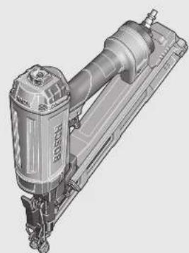
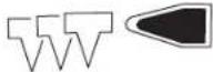
The numbering of the product features refers to the illustration of the pneumatic tool on the graphics page.
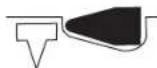
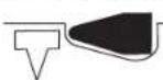
1 Workpiece protector
2 Discharge lock-off
3 Clamping lever for opening/closing the shot duct
4 Air outlet with adjustable exhaust cap
5 Trigger
6 Selector switch for actuation system
7 Handle
8 Air connector
9 Storage for workpiece protector
10 Magazine
11 Magazine slider
12 Thumbwheel for depth stop adjustment
13 Outlet
14 Air-connection coupling
15 Supply-air hose
16 Nail strip*
17 Magazine spring
18 Nail pusher
19 Driver blade
*Accessories shown or described are not part of the standard delivery scope of the product. A complete overview of accessories can be found in our accessories program.
Technical Data
| Compressed-air nailer GSK 64-34 | |
| Professional | |
| Article number | 3 601 D91 902 |
| Driving forceat 6.3 bar (91 psi) | Nm 34.4 |
| Actuation systems- Single actuation with safety run | ● |
| - Contact actuation | ● |
| Fastener-Type | Nail stripBrads |
| -L e n g t h | mm 32-63 |
| -D i a m e t e r | mm 1.8 |
| Magazine angle | ° 34 |
| Magazine capacity, max. | 100 |
| Engine oilSAE 10, SAE 20 | ml 0.25-0.5 |
| Internal volume | ml 330 |
Compressed-air nailer GSK 64-34
Professional
| Rated pressure | bar 4-8 | |
| Connecting thread | " | 3 |
| Supply-air hose | ||
| - Max. operating pressure at 20°C | bar | 10 |
| - Inner diameter of hose | " | 3/8 |
| -Max. hosed length | m | 30 |
| Air consumption per driving procedureat 6.8 bar (100 psi) | I | 1 |
| Dimensions | ||
| -He i g h t | mm | 307 |
| -W i d t h | mm | 79 |
| -L e n g t h | mm | 320 |
| Weight according to EPTA-Procedure01/2003 | kg 1.86 |
Noise/Vibration Information
Measured noise values determined according to EN 12549.
Typically the A-weighted noise levels of the pneumatic tool are: Sound pressure level 102 dB(A); sound power level 115 dB(A). Uncertainty K = 2 dB.
Wear hearing protection!
Overall vibrational values determined according to EN ISO 20643: Vibrational emission value a_h < 2.5 m/s^2 . Uncertainty K = 1.5 m/s².
Declaration of Conformity C
We declare under our sole responsibility that the product described under "Technical data" is in conformity with the following standards or standardization documents: EN 792 according to the provisions of the directives 2006/42/EC.
Technical file at:
Robert Bosch GmbH, PT/ESC,
D-70745 Leinfelden-Echterdingen
Dr. Egbert Schneider
Dr. Eckerhard Strötgen
Senior Vice President
Head of Product
Engineering
Certification

Robert Bosch GmbH, Power Tools Division
D-70745 Leinfelden-Echterdingen
Connecting the Air Supply (see figure A)
Make sure that the pressure of the compressed-air system is below the maximum permitted rated pressure of the pneumatic tool. Firstly, set the air pressure to the lower value of the recommended rated pressure (see "Technical Data").
When in doubt, check the pressure at the air inlet with a pressure gauge with the pneumatic tool switched on.
For maximum performance, the values for the supply-air hose 15 (connection thread, maximum operating pressure, inner hose diameter, maximum hose length; see "Technical Data") must be observed.
The compressed air supplied should be free of foreign material and moisture to protect the tool from damage, contamination, and the formation of rust.
All fittings, connecting lines and hoses must be dimensioned for the pressure and the required air volume.
Avoid restrictions in the air supply, e.g., from pinching, kinking, or stretching!
Connecting the Air Supply to the Pneumatic Tool
- Empty the magazine 10.
(See "Emptying the Magazine", page 18)
For the following worksteps, a fastener can be discharged when interior parts of the pneumatic tool are not in the starting position due to repairs, maintenance or transport.
- Connect the air connector 8 with a supply-air hose 15 equipped with an air-connection coupling 14.
- Check the proper function by placing the outlet 13 or the rubber work piece protector 1 of the pneumatic tool onto a piece of scrap wood or wood material, and discharging once or twice.
Loading the Magazine (see figures B1-B4)

Disconnect the air supply before making any adjustments, changing accessories, or placing the pneumatic tool aside. This safety measure prevents accidental starting of the pneumatic tool.
Use only original Bosch accessories (see "Technical Data"). The precision parts of the pneumatic tool such as the magazine, the outlet and the shot duct are matched to Bosch staples, nails and brads. Other manufacturers use other steel qualities and sizes.
Using fasteners not permitted, can damage the pneumatic tool and cause injuries.
While loading the magazine, hold the pneumatic tool in such a manner that the outlet 13 is not pointed at your own body or at other persons.
- Clean and lubricate the magazine slider 11 as required and make sure that the magazine 10 is not dirty/soiled.
- Insert a fitting nail strip 16 in the T-slot at the end of the magazine 10. When doing this, the nail tips must be inserted first.
- Push the nail strip in the magazine toward the front until the last nail is positioned in front of the magazine spring 17.
Note: A lock function of the magazine slider prevents the pneumatic tool from being started with an empty magazine. The discharge lock-off cannot be pressed in and blank firing is thus prevented.
- Press the pretensioned nail pusher 18 against the magazine slider 11 and at the same time, pull the magazine slider completely to the end of the magazine 10.
Note: The magazine slider must slide back with only low force (finger-pressure). A tight-running magazine slider causes the nails to be driven in at an incorrect angle.
- With the nail pusher 18 pressed, carefully guide the magazine slider 11 toward the front until the nail pusher is over the last nail, thus pushing the nail strip in the magazine completely to the front.
Note: Do not let the magazine slider snap back without guiding it. Otherwise, the magazine slider could become damaged, and there is danger of your fingers being caught or pinched.
18 | English
Operation
Actuation systems
The pneumatic tool can be operated with two different actuations systems:
- Single actuation with safety run
With this actuation system, the discharge lock-off 2 must first be firmly pressed against the workpiece. A fastener is not discharged until the trigger 5 is pulled.
Afterwards, further discharging procedures can only be actuated, when the trigger and the discharge lock-off have first been set back to the starting position.
- Contact actuation
With this actuation system, the trigger 5 must be pulled first. A fastener is always discharged when the discharge lock-off 2 is firmly pressed against the workpiece while the trigger is pressed.
This enables a higher working speed to be achieved.
The actuation system is set via the selector switch 6.
Starting Operation

Disconnect the air supply before making any adjustments, changing accessories, or placing the pneumatic tool aside. This safety measure prevents accidental starting of the pneumatic tool.
Working with Single Actuation (see figure C)
- Press selector switch 6 inward and at the same time pivot it to the bottom position until it engages.
The actuation system "single actuation" is set.
- Firmly position the outlet 13 or the rubber workpiece protector 1 on the workpiece until discharge lock-off 2 is pressed in completely.
- Afterwards, briefly press trigger 5 and release again.
A nail is discharged. - Allow the pneumatic tool to bounce back from the workpiece.
- For another driving procedure, completely lift the pneumatic tool from the workpiece and position it firmly at the next desired location.
Working with Contact Actuation (see figure D)
- Press selector switch 6 inward and at the same time pivot it to the upper position until it engages.
The actuation system "contact actuation" is set.
- Press and hold the trigger 5.
- Firmly position the outlet 13 or the rubber workpiece protector 1 on the workpiece until discharge lock-off 2 is pressed in completely. A nail is discharged.
- Allow the pneumatic tool to bounce back from the workpiece.
- For another driving procedure, completely lift the pneumatic tool from the workpiece and position it firmly at the next desired location.
- Move the pneumatic tool uniformly over the workpiece by lifting it off and applying it again.
Each time when applying the pneumatic tool while the discharge lockoff is pressed in, a nail will be discharged.
- As soon as the desired amount of nails have been driven in, release trigger 5 again.
Working Advice

Disconnect the air supply before making any adjustments, changing accessories, or placing the pneumatic tool aside. This safety measure prevents accidental starting of the pneumatic tool.
Check the proper function of the safety and actuation devices, and the tight seating of all screws and nuts each time before using.
Disconnect a defective or not properly operating pneumatic tool immediately from of the air supply and contact an authorised service agent for Bosch power tools.
Do not perform any incorrect manipulations on the pneumatic tool. Do not disassemble or block any components of the pneumatic tool, such as the discharge lock-off.
Do not carry out "emergency repairs" with unsuitable means. The pneumatic tool is to be maintained regularly and properly (see "Maintenance and Cleaning", page 19).
Avoid any weakening and damage whatsoever of the pneumatic tool, e.g., through:
- Imprinting or engraving,
Retrofitting measures not approved by the manufacturer,
Guiding along templates manufactured of hard material, e.g. steel, - Dropping on or sliding over the floor,
-Using as a hammer, - Applying any kind of force.
Make sure to check whatever is below or behind your workpiece. Do not shoot nails into walls, ceilings or floors, when persons are behind them. The nails can burst through the workpiece and injure someone.
Do not shoot a nail onto an already driven-in one. This could cause the nail to deform, the nails could become jammed or the pneumatic tool could move uncontrolled.
When the pneumatic tool is used under cold ambient conditions, the first nails will be driven in slower than usual. Once the pneumatic tool has warmed up during working, normal operating speed will be regained.
Avoid blank shots in order to reduce the wear of the impact striker.
For longer work breaks or after finishing work, disconnect the pneumatic tool from the air supply and empty the magazine.
Emptying the Magazine (see figures E1 - E2)
- With the nail pusher 18 pressed, pull the magazine slider 11 to the rear until the last nail is free; then carefully guide the magazine slider toward the front to the beginning of the magazine 10.
Note: Do not let the magazine slider snap back without guiding it. Otherwise, the magazine slider could become damaged, and there is danger of your fingers being caught or pinched.
- Turn the pneumatic tool so that the nails in the magazine slide back to the magazine spring 17.
- Push the magazine spring down and allow the nails to slide past the nail pusher 18 out of the magazine 10.
Adjusting the Depth Stop (see figure F)
The driving depth of the nails can be set with thumbwheel 12.
Empty the magazine 10.
(See "Emptying the Magazine", page 18)
Nails are driven in too deeply:
To reduce the driving depth, turn thumbwheel 12 in anticlockwise direction.
or
Nails are not driven in deep enough:
To increase the driving depth, turn thumbwheel 12 in clockwise direction.
- Refill the magazine.
(See "Loading the Magazine", page 17) - Test the new driving depth on a test workpiece. Repeat the worksteps as required.
Removing the Discharge Lock-off
For service or cleaning purposes, the discharge lock-off 2 can be removed.
- Turn thumbwheel 12 in clockwise direction, until the first thread can be seen.
- Carry out 6 further turns in clockwise direction. The discharge lock-off 2 can now be pulled off.
To reinsert again, slide discharge lock-off 2 back into the holes intended for this, and turn thumbwheel 12 in anticlockwise direction until no more threads can be seen.
Clearing Jams (see figures G1-G3)
Single nails can become jammed in the shot duct. If this should occur frequently, please contact an authorised service agent for Bosch power tools.
- Empty the magazine 10.
(See "Emptying the Magazine", page 18) - Press clamping lever 3 down so that the shot duct opens.
- Remove the jammed nail. For this, us a pair of pliers, if required.
- When driver blade 19 is extended, push it back into the piston using a lubricated screwdriver or other suitable lubricated object.
Lubricate the shot duct with 2 -3 drops of engine oil (SAE 10 or SAE 20). - Close the shot duct, hang the clip of clamping lever 3 into the hooks on the shot duct and then push the clamping lever up again.
- Refill the magazine. (See "Loading the Magazine", page 17)
Note: When the driver blade does not return after clearing a jam, please contact an authorised service agent for Bosch power tools.
Changing the Workpiece Protector (see figure H)
The workpiece protector 1 at the end of the discharge lock-off 2 protects the workpiece until the pneumatic tool is correctly placed for the driving procedure.
The workpiece protector can be removed and replaced.
- Pull the workpiece protector from the discharge lock-off.
- Push the new workpiece protector via the open end over the discharge lock-off.
Note: A spare workpiece protector can be stored at the top side of magazine 10. For this, push the workpiece protector into the depot 9.
Adjustable Air-outlet cap (see figure 1)
With the adjustable exhaust cap at the air outlet 4, it is possible to deflect the exhaust air away from yourself or the workpiece.
Transport and Storage
For transport, disconnect the pneumatic tool from the air supply; especially when using ladders or moving in an unusual stance or posture.
At the workplace, carry the pneumatic tool only by the handle 7 and with the trigger 5 released.
Always store the pneumatic tool disconnected from the air supply and at a clean and dry location.
When not using the pneumatic tool for a longer period of time, cover steel parts with a fine oil coating. This prevents the formation of rust.
Maintenance and Service
Maintenance and Cleaning

Disconnect the air supply before making any adjustments, changing accessories, or placing the pneumatic tool aside. This safety measure prevents accidental starting of the pneumatic tool.
If the pneumatic tool should fail despite the care taken in manufacture and testing, repair should be carried out by an authorised customer services agent for Bosch power tools.
In all correspondence and spare parts orders, please always include the 10-digit article number given on the type plate of the pneumatic tool.
Have maintenance and repair work carried out only through qualified persons. This will ensure that the safety of the pneumatic tool is maintained.
An authorized Bosch after-sales service agent will carry out this work quickly and reliably.
Lubricating the Pneumatic Tool (see figure J)
When the pneumatic tool is not connected to a maintenance unit, it must be lubricated at regular intervals:
- For light-duty use 1x per day.
- For heavy-duty use 2x per day.
Apply 2-3 drops of lubricant into air connector 8. Do not apply too much lubricant, which could then accumulate in the pneumatic tool and be emitted via air outlet 4.
Use only the lubricants recommended by Bosch.
SAE 10 mineral engine oil (for use at very cold ambient conditions)
SAE 20 mineral engine oil
Observe all applicable environmental regulations when disposing of old grease and solvents.
20 | English
Maintenance Schedule
Always keep air outlet 4, discharge lock-off 2 and trigger 5 clean and free of foreign material (dust, chips, sand, etc).
Clean the magazine 10. Remove any plastic or wood chips that may accumulate in the magazine during operation.
Clean the pneumatic tool in regular intervals using compressed air.
| Measure Explanation Action | ||
| Draining the exhaust filter daily. | Prevents the accumulation of dirt/ debris and moisture in the pneumatic tool. | - Open the drain valve. |
| Keeping the lubricator filled at all times. | Ensures the lubrication of the pneumatic tool. | -Fill lubricator with the recommended lubri-cants.(See "Lubricating the Pneumatic Tool", page 19) |
| Cleaning the magazine 10 and magazine slider 11. | Prevents the jamming of nails. - Blow out the mechanism of the magazine/magazine slider daily with com-pressed air. | |
| Ensuring that the discharge lock-off 2 functions properly. | Promotes your work safety and efficient usage of the pneumatic tool. | - Blow out the mechanism of the discharge lock-off daily with compressed air. |
| Lubricating the pneumatic tool. | Reduces the wear of the pneumatic tool. | - Apply 2 - 3 drops of lubricant into air connec-tor 8.(See "Lubricating the Pneumatic Tool", page 19) |
| Draining the compressor. | Prevents the accumulation of dirt/ debris and moisture in the pneumatic tool. | - Open the drain valve of the compressor tank. |
Correction of Malfunctions
Problem Cause Corrective Measure
| The pneumatic tool is ready for operation but no nails are discharged. | A nail is jammed in the shot duct. - Clear the jam. | (See "Clearing Jams", page 19) |
| The magazine slider is 11 defective. | - Clean and lubricate the magazine slider 11 as required and make sure that the magazine 10 is not dirty/soiled. | |
| The spring of the magazine slider is too week or defective. | - Contact an authorised service agent for Bosch power tools.Have the component replaced there. | |
| The fasteners being used are not permitted. - Use only original accessories.Only the fasteners (nails, staples, etc.) specified in table "Technical Data" may be used. | ||
| The magazine 10 is empty. - Refill the magazine. | (See "Loading the Magazine", page 17) | |
| The nails are discharged very slowly and with too little pressure. | The rated pressure of the compressed-air supply is too low. | - Increase the compressed-air supply. 8 bar may not be exceeded. |
| The driver blade is damaged. | - Use only the lubricants recommended by Bosch.(See "Lubricating the Pneumatic Tool", page 19) | |
| The sealing ring of the piston is worn or damaged. | - Contact an authorised service agent for Bosch power tools.Have the component replaced there. | |
| The buffer is worn. | - Contact an authorised service agent for Bosch power tools.Have the component replaced there. | |
| The length and diameter of supply-air hose 15 do not correspond with the data of this pneumatic tool. | - Use a supply-air hose with the correct dimensions.(See "Technical Data", page 16) | |
| The supply-air hose 15 is bent/creased. | - Correct the bend/crease in the supply-air hose. | |
| Problem Cause Corrective Measure | ||
| The nails are driven in too deep. | The rated pressure of the compressed-air supply is too high. | - Reduce the compressed-air supply. 4 bar may not be fallen below. |
| The depth stop is set too deep. - Adjust the depth stop to the desired depth.(See "Adjusting the Depth Stop", page 18) | ||
| The buffer is worn. - Contact an authorised service agent for Bosch power tools.Have the component replaced there. | ||
| The nails are not driven in deep enough. | The rated pressure of the compressed-air supply is too low. | - Increase the compressed-air supply. 8 bar may not be exceeded. |
| The depth stop is set too high. - Adjust the depth stop to the desired depth.(See "Adjusting the Depth Stop", page 18) | ||
| The length and diameter of supply-air hose 15 do not correspond with the data of this pneumatic tool. | - Use a supply-air hose with the correct dimensions.(See "Technical Data", page 16) | |
| The supply-air hose 15 is bent/creased. | - Correct the bend/crease in the supply-air hose. | |
| The pneumatic tool skips nails or has a too large cycle feed. | The fasteners being used are not permitted. - Use only original accessories.Only the fasteners (nails, staples, etc.) specified in table "Technical Data" may be used. | |
| The magazine 10 is not operating correctly. | - Clean and lubricate the magazine slider 11 as required and make sure that the magazine 10 is not dirty/soiled. | |
| The spring of the magazine slider is too weak or defective. | - Contact an authorised service agent for Bosch power tools.Have the component replaced there. | |
| The sealing ring of the piston is worn or damaged. - Contact an authorised service agent for Bosch power tools.Have the component replaced there. | ||
| Frequent jamming of nails in the shoot duct. | The fasteners being used are not permitted. - Use only original accessories.Only the fasteners (nails, staples, etc.) specified in table "Technical Data" may be used. | |
| - Contact an authorised service agent for Bosch power tools. | ||
| The driven nails are bent. | The driver blade is damaged. - Contact an authorised service agent for Bosch power tools.Have the component replaced there. | |
| Contrary to working with normal operat-ing speed, the nails are not driven in deep enough at higher operating speed. | The interior diameter of the supply-air hose is too low. | - Use a supply-air hose with the correct dimensions.(See "Technical Data", page 16) |
| The compressor is not suitable for fast operating speeds. | - Use a compressor that is sufficiently dimensioned for the number of connected pneumatic tools and the operating speed. | |
Accessories
For more information on the complete quality accessories program, please refer to the Internet under www.bosch-pt.com or contact your specialist shop.
After-sales Service and Customer Assistance
Our after-sales service responds to your questions concerning maintenance and repair of your product as well as spare parts. Exploded views and information on spare parts can also be found under:
www.bosch-pt.com
Our customer service representatives can answer your questions concerning possible applications and adjustment of products and accessories.
Great Britain
Robert Bosch Ltd. (B.S.C.)
P.O.Box 98
Broadwater Park
North Orbital Road
Denham
Uxbridge
UB95HJ
Tel. Service: +44 (0844) 736 0109
Fax:+44(0844)7360146
E-Mail: boschservicecentre@bosch.com
22 | Français
Ireland
Origo Ltd.
Unit 23 Magna Drive
Magna Business Park
City West
Dublin 24
Tel. Service: +353 (01) 4666700
Fax: +353 (01) 466 68 88
Australia, New Zealand and Pacific Islands
Robert Bosch Australia Pty. Ltd.
Power Tools
Locked Bag 66
Clayton South VIC 3169
Customer Contact Center
Inside Australia:
Phone:+61 (01300) 307 044
Fax: +61 (01300) 307 045
Inside New Zealand:
Phone: +64 (0800) 543 353
Fax: +64 (0800) 428570
Outside AU and NZ:
Phone: +61 (03) 9541 5555
www.bosch.com.au
Republic of South Africa
Customer service
Hotline: +27 (011) 6519600
Gauteng - BSC Service Centre
35 Roper Street, New Centre
Johannesburg
Tel.: +27 (011) 4939375
Fax: +27 (011) 4930126
E-Mail: bsctools@icon.co.za
KZN - BSC Service Centre
Unit E, Almar Centre
143 Crompton Street
Pinetown
Tel.: +27 (031) 7012120
Fax: +27 (031) 7012446
E-Mail: bsc.dur@za.bosch.com
Western Cape - BSC Service Centre
Democracy Way, Prosperity Park
Milnerton
Tel.: +27 (021) 5512577
Fax: +27 (021) 5513223
E-Mail: bsc@zsd.co.za
Bosch Headquarters
Midrand, Gauteng
Tel.: +27 (011) 6519600
Fax: +27 (011) 6519880
E-Mail: rbsa-hq.pts@za.bosch.com
Disposal
The pneumatic tool, accessories and packaging should be sorted for environmental-friendly recycling.
Observe all applicable environmental regulations when disposing of old grease and solvents.
If your pneumatic tool can no longer be used, deliver it to a recycling centre or return it to a dealer - for example, an authorized Bosch after-sales service agent.
Subject to change without notice.
Français
Senior Vice President
Head of Product
Engineering
Certification
ppa. 1. i.v. Mioyceu
Robert Bosch GmbH, Power Tools Division
D-70745 Leinfelden-Echterdingen
Robert Bosch (France) S.A.S.
Senior Vice President Head of Product
Engineering Certification

Robert Bosch GmbH, Power Tools Division
D-70745 Leinfelden-Echterdingen
Dr. Egbert Schneider Dr. Eckerhard Strötgen Senior Vice President Head of Product Engineering Certification

N2 与 O2 溶后反应:
Robert Bosch GmbH, Power Tools Division D-70745 Leinfelden-Echterdingen Leinfelden, 22.03.2011
Montagem
Senior Vice President
Head of Product
Engineering
Certification

Robert Bosch GmbH, Power Tools Division
D-70745 Leinfelden-Echterdingen
Senior Vice President Head of Product
Engineering Certification
ppa_1 . 与 D 相等
Robert Bosch GmbH, Power Tools Division
D-70745 Leinfelden-Echterdingen
Senior Vice President
Engineering
Dr. Eckerhard Strötgen
Head of Product
Certification

Robert Bosch GmbH, Power Tools Division
D-70745 Leinfelden-Echterdingen
Brug af违法犯罪, including the following:
Bosch Service Center
Telegrafvej 3
2750 Ballerup
Tel. Service Center: +45 (4489) 8855
Fax: +45 (4489) 87 55
E-Mail: vaerktoej@dk.bosch.com
Bortskaffelse
Senior Vice President Head of Product
Engineering Certification

N 都是
Robert Bosch GmbH, Power Tools Division
D-70745 Leinfelden-Echterdingen
- Spikar drives in for djupt:
Bosch Service Center
Telegrafvej 3
2750 Ballerup
Danmark
Tel.: +46 (020) 414455
Fax: +46 (011) 187691
Avfallshantering
Senior Vice President
Head of Product
Engineering
Certification
Paa
Robert Bosch GmbH, Power Tools Division
D-70745 Leinfelden-Echterdingen
-innslaingellinngravering.
Senior Vice President
Head of Product
Engineering
Certification
ppa.
Robert Bosch GmbH, Power Tools Division
D-70745 Leinfelden-Echterdingen
Senior Vice President
Head of Product
Engineering
Certification

Robert Bosch GmbH, Power Tools Division
D-70745 Leinfelden-Echterdingen
Ta kaipata dev mnyovrae npakoc baet
Tupotovtpoiako 12 upoaiqipopaia va auioe to daoc kappapatoc.
-Eavayepiote to yeiipotnpa.
(BaIe «Fuaou yuoiippa),0ai90)
EAEYcTo vco Baooc KApPauoC oEv aDokmaotko uno katepyaia Teuixio.
Av xpeiaotei, eanvalaβcte Tdiabikaia.
ApaieoTnC aopaleiac anoeaeuoc
IaepyaocouvnpnncnKbapouu npopeirevaopaedeTyn aapacia anoedecuong2.
FupioTeTovtpoxiao12peoAoayiaknopaepxa va cipaviotc npwnBoAraouoneipuatoC
-ΓupioTeTovoynoβaoucakoum6pocεμωpaoiaknφopa.
Tupa unopeite va aphaipoeote tny aqpaia ano6aeueuong 2.
Tia va Tny enavatonoBteiOe ciayetnv aoPaeia anoBoeuanc 2 otic avtioaoce npoBaeIoupevecTpunekai yupiote tv troxioko puohnC 12 peap avtiBEN TNC wpoLoyakic,expi va kpuptein npwn B0Ata Tou oneipmuatoc.
Apaipoeon opnvouevovkappov (Blenc eokocG1-G3)
ev anokkietai, eaa otny kavn va oynwouov npovuva kappia. 2e nepiwnou nou auto ouaibaive ouxva,napakaloume va eptheta ae enaep me eva coguaobotmucoataauga Service ng Bosch.
-Abeidote to ycmuippa 10.
(BaeneAeiaquayeiOtnpa),0kla91)
- Pntnne npoc ta katu to oxo oovphienc 3 evi va unopoeetve avoiie Tny kcvn.
-ApaipoeTo oynovmoevo kappi,ev avaykn mia tavaia.
-Orav n mntpa 19 exeBeyE EwOHTe TnV naI pOa oTo eBolpe eva ypaapiaepo katoaibiE h eva dA lo kataaANo, ypaapiaepo avtkeipevo.
- Paaapete Tny kavn 2 -3 orayovcc laoiu kivtnipsa SAE 10 nr SAE 20).
- Kaeiote tyn kavn, avapntote to eaaou taou poxoh ouoayfnc 3 oto yavTc nC kavnc kal aokolouwoc natote to poxho naipoc ta endvw.
Eavayepiote to yepiotnpa.
Senior Vice President
Head of Product
Engineering
Certification
Paa
N 都是
Robert Bosch GmbH, Power Tools Division
D-70745 Leinfelden-Echterdingen
Bosch San. ve Tic. A.S.
Ahi Evran Cad. No:1 Kat:22
Polaris Plaza
80670 Maslak/Istanbul
Müsteri Danisman: +90 (0212) 335 06 66
Müsteri Servis Hatti: +90 (0212) 335 07 52
Tasfiye
Senior Vice President
Head of Product
Engineering
Certification
Paa
Robert Bosch GmbH, Power Tools Division
D-70745 Leinfelden-Echterdingen
Robert Bosch Sp. z o.o.
Senior Vice President Head of Product
Engineering Certification
Paa.
Robert Bosch GmbH, Power Tools Division
D-70745 Leinfelden-Echterdingen
Bosch Service Center PT
K Vapence 1621/16
692 01 Mikulov
Dr. Egbert Schneider
Dr. Eckerhard Strötgen
Senior Vice President
Head of Product
Engineering
Certification
ppa
Robert Bosch GmbH, Power Tools Division
D-70745 Leinfelden-Echterdingen
Dr. Egbert Schneider Dr. Eckerhard Strötgen Senior Vice President Head of Product
Engineering Certification
Robert Bosch GmbH, Power Tools Division D-70745 Leinfelden-Echterdingen Leinfelden, 22.03.2011
Osszeszerelés
CoaepKHTe BaIe pa6ooyee MeTO BcHCTote H xopoO
OCBueeHHbM. BecnpaOK Ha pa6oem MeCTe H HeocBeeHbIe yacTkn pa60t bMOrT pINBEcTH K HeCuaCTbIM CAYaRm.
He pa6oatae c THEBMONHCTpymEHTOM BO B3pbIBOOANTAHOM TOMEueHH, B KOTOPOM HAXOATC TROPUHE XHKOCTH, F3bI HAN TIIaB. PnO 6pa6oTKe DaTAAHO B03MOKHO B03HNKHOBEHHe NCKP, KOToPbIe BeAyt K BoCTaMaHEHIO TbIAI MAN IaPOB.
Ppna pabote c nHEBMOHcTpymENTo He aOtyckaTe 6An3ko K Baewemy pa6oemy Mecy AIOBObIthbIX, Deten H NoctopOHnX AN.3TN ANa MORYT OTBAeYBaWe BHHMaHne N Bbl IOTepReTe KOHTPOAb HaNTHEBOHcHTpyMeHToM.
Be30tachOCTb THeBMaTHuecknx HnCTpyMeHToB
IpHMeHnTe CxAby 5-fo Kaacca KaucctBa nDIN ISO 8573-1 HnHnBMyaBbHb6AOK B03AxOToAroTOBKn B6An3n THEBMnHCTpymEtA. AAR 3aunTbI THeBMOnHCTpymEtAOTIOBpeXeHn, 3arpa3HeHn N O6pa3OBaHHN KOPPO3N IOdaBaembl CxAby BO3Ax DOxKeH 6bTb ONUeH OTIOCTOpOHHX YAcTHu N BAaHn.
PtpOBepRte npHcoeHHHeHH HHHHH THTAHN.Bce 6AOKN BO3yX0TO4OTOBKN, MyfBt bI IaAHTn DOAkhbI 6bITb paCCHTaHbHa DaBAEHeH pACxoADBO3yXa corACHO TEXHNUECKM daHbIM. H3Koe DaBAEHeO pTnCATEbHO BANET Ha FyHKUHO THEBMONHCTpyMeHTA, 3aBbIeHHOE DABAEHE MOxET PpHBcET N KIOBpeKeHHM n TpaBMam.
3aunuatae 10nepnerhOB, nepexHMOB, pactbopHTaeH N OCTpbix KpOMOK. 3auuuaite 11aaHnT OBO3eCTBn IOBbIeHHbIX TEMIEPATyp, McAa H BpaauoHxxCdTeaJe. HeMeDAEHHO 3aMeHrTE IOBpeXeHHbI bAAHr. DeΦeKTHaAMHNITAHNMOKET PnPBecTN K6bHOeMY BOKpyr Ce6raaHry CkatoROB3yxA h CTaTBnPPHHOH TpABM. IIOHHTAR B 603ayx PbIbN hNCTpykkMOKET BblBaT TBKeAbe TpABMbI rA3.
CAeAHTe 3a TEM, yTO6bI XOMYTHKN IAAHROB 6bIAH BcERda KpeKIO 3aTAYbI. CλaO 3akPeJIaENHHbI HAI IOBpeXeAHHbI XOMYTHKN IAAHrMA MOrY CTaTB IIpHUNHO YTeKN BO3dYxa.
Be3oTachOCTbAIODeE
Bybte BHHMATEAbHbIMn,CAeNTe 3a TEM,TOBbIeAeTe INpoDyMaHHo HauHHaHTe pa6OTc CTHEBMOHNCTPymEtOM.He IOAB3yTEcB THeBBMOHNCTPymEtOM B YCTaAM COCTOHHN HAN, ecAn BbI hXoAHTEcB ToB BAHNHEm HApKToKNOB, CHTpTHbIX HAHTKOH HAAkAPCTB.ODIH MOMEHT HeBHMATeABHoCTN Ipi pa6Ote CTHEBMOHNCTPymEtOM MOKET IPIHBecTNI K cepbe3HbIM TpaBMam.
PIMHeHnE HANBHAaHbIe CpeACTBa 3auHTbH Bcerda 3aunThbue OKn. PImHeHHe CpeCTB INAHBnAaBHOH 3auHTbI, KaTO IbIae3aunTHoro peCINpaTopa, CteUO6ByH, 3auHTHO rMa, CpeCTB 3auHTbOpraHOB CAYxa, B 3ABNCMOCTN OT BHa aYcAobn pa60tbc INEBMOHNCTpyMeHToM, CHINKaET PNCK TpAbMNPOBaHH.
IpeodBpaaHHepehamepeHoe BkUoyehne.IpeaIOAIOUeHHm THEBMONHcTpymHa K Bo3dXoCH6KeHHIO,TeepAtem,Kak BbI BO3bMeteroBpyKn ItpaHcnpTIpOBkoIpoBebpteero BbIKAOUeHHOe COCTOHHe.YepKaHHe NlaBaHaBbIKAOyATEe TIPn TEPEHOCE THEBMONHcTpymHa MAn IOAIOUoyehNEBKAIOUeHHOTo THeBMONHcTpymHa K HcTOUYHKY Bo3dYx apeBaToHEcuaTHbIM CAYaAMN.
IpeaBkauoHemTHHeBMOnHCTpyMeHa y6epHeYcTaHOBOuHb HnctpyMeHT.YCTaHOBOUHb HnCTpyMeHT,HAXOAAuHCA BO BpaAIOueiCayactn THeBMOnHCTpyMeHa,MOXETIPINBecTKN TpaBMAM.
HHepeoehnbaTece6B.Cerda3aHHMaTeyctOuHBOE IOAOXEHNE HBCERdA BbIePKNBaHTpepHOBeCne.YcOHTNBOE IOAOXEHNE COOTBETCTBYIOOEIOAOXEHNE KOpTpyCaIO3BOAT BaM AUYUe CnPaBnTBcRc THeBMOnHCTpyMeHtOM B HeOXHaHHbIX CNTyaunx.
HochtoaoaoyoOeJyHe hochtoipokyo OeJy H ykpaewn. Aepxnte BOACbI, oEeJy H nepuATKn B CTPOHE OT ABKyuXcA qacte. IUPOKa OeJya, ykpaewn HAAN DHHbIe BOACbIMOTy6bTb3aTAYHbI BpaauOHMNCA qACTRM.
PnHaAnuHn B03MoXHOCTN yCTAHOBKN TbIaTeoCsbIBaOuNX N TbIaEc6OpBHX yCTPOJCTNBIOpeRrte Hx PnHoeMHHeHne H
IpABHbHOe HcIOAb3OBAHHe. IcIOAb3OBaHHe 3THX yCTPOINCTB CHKAET OAnCHOCTb OT BO3AEJCTBNA IIbAH.
HeBaIbIXaIteOtpa6oTahHbB03aYx.CAeIATE3aTEM,tyo6bl OTPa6oTahHbB03aYx He TIOIaAaBra3a.OTpa6oTaHbB03aYx H3THEBMONHCTpyMeHTaMOKET CQePkaTbBOy,MAcAo, MetaAMueCKHe qACTuBn 3aqr3HeHHN,IIOTaAOUHe N3 KOMTIpeCCopa.3To MOKET HMeTB BpeADHO BAHNHE Ha3DopOBBe.
TuaTeAhoe 06xoxKeHHe CTHeBMOHCTpyMeHTAMN Hx TpaBbHOe TPmMeHHe
Aa yepkHBnHn HOTOpbl DaTAAH NoAbyTEcB 3axmmhymyctpoCTbAMn HANTHCKAMn. YepkBaAeTaABypyKoHnPiNxHMaaee KteLy, BHe MoKeTe HaDeXHOYpIpaABTb THEBMOnHCTpyMeHTOM.
HepepykaTe THEBMONHCTPymeHT. HcnoA3yte daBaaew pa6otbI pdeHa3haueHHb IAA TTOI THEBMONHCTPmeyT.C IOxOaIMM THEBMONHCTPymeHTOM Bpa6otaete Auyue HaedKHeB B yka3AHOM dHaia3OHE MOUHOCTN.
HeIIOAB3yIeTcBTHEBMOHnCTpyMeHToC HcHcTpapbHBMBAIKAOyAEM.IHEBMONHCTpyMeH,KOTOpB He IIOADaETCBKIAOHN BILKAIOUeyHHO,OTACEHNOJAOXeH6bItbOTpMoHTIpOBaH.
OTKIAUaHTe NOaCy cKaTOrO B03Axya DO hauaHa HAcTpOKn HnCTpymHtA, CMeHbIOcHAcTK HAn IpeXe Che M BByIyCTHb THeBMOnHCTpyMHTn pyk. 3Ta Mepa IpeoctOpoxHOCTn IpeoTbpaaet HepeHaMepeHHb Iyck THeBMOnHCTpyMHTa.
XpaHHTe HcHToA3yEmbI TeBMOHCTpyMeHb B HeOcraEaOMM AAR DetTe MeCte. He pa3peaIte IaB3OBaTbCRA THeBMOHCTpyMEHOTOM AHzAM, KOTOpBIE He3HAKOMbl C HMM HAN HE YHTaAH HACToHxN HcTpyKuH. THeBMOHCTpyMeHb OtaChb BYkax HEOTbTHbIX AMU.
TtateBho yxaknBaIte 3a THeBMONHCTpyMeHToM. PpOePnTe 63ytpueHyIO fynKIOHO XoAD BnKxyuXcraCTe THeBMONH CTpyMeHTA, OTCYCTBNE IOAMOK HAN TOBpeXdEHN, OTPHaTeAHO BAHOxH NaYHKIO THeBMONHCTpyMeHTA. TObpeXdEHbIe cactn DOAnh b6Itb OTPMOHTPOBAHbI Do NcTOAb3OBAHn THeBMONHCTpyMeHTA. IaoXoe oCayknaHHe THeBMONHCTpyMeHToB RABaETc pINHHo 6oALBOrO YnCa HeCACTbIX CAYaE.
TIPMHMeHnTE THeBMOHnCTpymEnT,TPHnAaExxHOCTn,pa6Oue HnCTpymEnbTI N.T.B COOTBETCTBn CHACTOaHHMn HHCTpyKuHnM. YHTbBAte TpN 30m ycaOBn H Bn pa6oTb.IcTOa30BaHHe THeBMOHnCTpymEtA DApYrNx,HeIpeyCMOTpeHHbIx pa60t MoXeT PnBBecn K OToaChbIM CHTaUHnM.
CepBnC
Pemont Baewero THEBMONHCTpymeHTA TOpyaTe ToaBko KbaanHnpoBaHHOMy TepcoHaY HToaBko C HcToa3oBAHHem opHnHaabhix 3aTuaCeT. 3TNM o6ecTneuBaetc8eOtaNacHOCTb THEBMONHCTpymeHTA BaaBHeWEM.
Yka3aHnI IO TEXHnke 6e3oTachOCTN DAITHEBMaTHuecknx CkO6o- N TB03e3a6NBbIXHHCTpymEHTOB

IcTIOAb3yIte 3aunTHbIe OcKN.
Bcerda HcxOaHTe H3 TOrO, YTO BTHEBMOHnCTpyMeHTe HaxoAHTcKpeTExhbl Maepna. He6peXHOe obaueHne cTHEBMONHCTpyMEHOT MOKeT PIPBecT N KHeOxHaHHOMByBbTAaKbBaHIO KpeTExHOro Maepna, BCaeCTBne Yero Bbl MoXeteTOAYHTb TpaBMbl.
Pycckn | 133
Aepkhte THeBMOHcTpymEt BO Bpempa60tak, YTO6bI Bbl He MORAN TopaHTb ToAOBy H TEAO pINB 03MOXHom PHKOWETE BCAECTBHe HEnCPTpaBHOCTe B CTeH THTAHN HAN HATAKHBHNA HHCTPymEtHa TBepAble MeCTa B3aTOTBE.
He HapabAAIe THeBMOHCTpyMeHT Ha ce6n Apynx AIOaE, HaxoAunxCn IObA3OCTn. BCAeCTBne HeoxKaHaHHOro Iycka HNCTpyMeHTa BbltaAKNBaETcKpeekhBl MaTePnaA, YTO MOKet TPnBeCTn K TpaBMam.
He BKAIOUaTe TNEBMOHCTPymET, Oka Bb He npctabAH erO npouHO K3aTOrOBKe. ECAH MEKAY TNEBMOHCTPymEMTOm 3aTOrOBKOH CET KOHTAKT, KpeIeKHB MaTePAH M0KET OTCKOHTb OT MEcTA KpeIeEHN H pINBEcTN K TepeRpy3e TNEBMOHCTPymEHa.

He pa6oata He naeCTHuaX Hn IIOmOctax,ecAH Bkauoyeha cnctema cTcycka KOntakthbI cnTcck. BvaCTHOCTH,3aPpeaaetc TpepeMaTaBcHa IOMOCTAX, AecTHuaX, CTpeMHNKx Hn IOObHbIX KOHCTpyKunx, KaK HAp., 6peWetKaX KpbII, OT OAnHO MecTa pa60bIKdpYrOmy, 3aKpbIbAtbNnKNHn Hn TeperopOAKH Hn OChaaTb, HAp., TpAHCnpthBle CpeACTBaHn BarOhbI, TpaHCTOpThBMn HnkCatopAMn. Ean Bby II pRn 3ToI CNCTeMe cTcyka CaUyaiHO pINCTabNTe THeBMOnHCTpymEt K 3aROTBKe IIpH HnKaHatom IpeOxApaHTeAE cTnyCKOBOro KpOuKa, KaKdbI pa3 6dET BItaAKnBaTc KpEnTeKhBm MatepeHa. 3To MoKET IIpNBeCTN KTPaBMam.
CaeHte 3a yCAOBHMn Ha MeCe pa6oTb. KpeNexHbIM MaTePhnM oKeT Ipo6HBaTb TOHKHe 3aROTOBKN Hn PpIpa6Tox HA yTaXn KpaNX 3aROTOBOK OTCKAKBaTb PNKOJETOM PaHHTb MIOeH.

OTKAOUHTe Ch6xHHe Bo3dyxa, ECAM KpeTExhbl MATEpHa3actPBA TTHEBMOHNCTpyMeHTI0DAKIOUeH K HCTOuHNY THTAHn, PIPYdAeHHM3ACTPRAEero KpeTExHOro MATEpHaA OH MOXET 6bIT CAYaHNO pINBEeH B DeCTBne.
Byte octopxHbI pH bHTBnBaHH 3actpBwero KpeTexHOro Maepna. CNTema MoKET HAXOHTBCa HA B3BOe I KpeENKbIM MaepnaM MoKET 6bITb BTOAKNHY C cAIO, KOra Ba BYe I PPO6OBaTb BtauHbEro.
He HcnoIb3yIte 3OT TnHEBMOnHCTpymEt DAaKpeTaeHHN 3AEkTpOPOBKn. OH He IpeHa3aHueH DAn IpOKaAKn 3AEkTpOPOBKn, MOKeT IOBPeADt b H3oAunIO 3AEkTPoKa6eAe IINBECTN K3AEkTPuCeCKOMy yApY H OtaCHOCTn POka.
HHKOrda He HcToTa3yTe KHeLoOpA HAn TOpOHe Ra3bI B KaueCTBe HcToUHKnKa 3HePrrn DAA THeBMOHcHcTpMeHa. TOpOHe ra3bl OTAChbl, OHMOrty CTaTb IIpHCHHO B3pbIbA THeBMOHcHcTpMeHa.
IIpHMeHNIE COOTBETCTBYOUHNE MetAONKATEAN DAA HAXOXDEHHNCKpbITbIX CHTEM 3AEKTPo,ra30-H BOOCHa6KeHHN HAn ObaaIteCb 3a CPTPABKO B MecTHOE PpeAPnTHe KOMMyHaBHOr CHO6KeHH. KOHTAKC 3AEKTPoPBOAOKMOKET IINPBECTN KTOXAPy HIOPAxeHHIO 3AEKTPoTOKOM.IOBpexDeHHe ra30IOPOBa MOxET IIINPBECTN K B3pbyIBYIOBpEXeHHe BOOIPBOOBA BeET K HAHeCEHHIO MATEpHaBHOr yUep6a.
PIOKaIOaHTe THeBMOHCTpymENT ToIbKO K Tpy6oIPBOAoAM, B KOToPbIX MAKCHMaIbHO DOOTyCTHMoe AAR THeBMOHCTpymEta DaBAeHne He MoKet 6bItb NpeBbIeHo 6Oaee Yem Ha 10%; npn 6OaIbEM DAABeHHN Tpy6oIPBOA CXaTOrO BO3Ayx Heo6XoAHMO OChACTHTb PerYAnTopOM DaBAeHHN (peyKuOHbIM KaanAHOM) KAAATAHOM ORpaHueHHN DAABeHHN. 3AbIeHHoe DaBAeHne MoKet
CTaTbIpHINHOcOeBpaBoTe HnTHOBpeKdHnTHEBMOHNCTpyMeHTA,TO MOxETIpHBecTKN TpaBMam.
OncaHne npoAkyTa n ycAyr

IpoHTHe Bce yka3aHHN H NCTpyKuHN IIO texHnKe 6e3oNaChocTh. YtuJeHHN B OTHoWeHHN yka3aHHN HNCTpyKuHN IIO TexHnKe 6e3oNaChocTH MOrYT CTaTb IpnHHoN IopaxeHHN 3AekTpueckHM TOKOM, IIOkapa n TRAEAbx TpaBM.
TpHMeHeHHe ITO Ha3HaueHmIO
THEBMONHCTpymEtIpeHa3aueHAA CoeMHHeHH 3AEMeHTOB IpiKPOBeAbHbIX paOToax,06WBKE DOCKAMN I cTpOnTeAbCTBe 6peWetOK,aTAkKe IPIH N3rTOBAAHN CTEHbIX/KPOBEAbHbIX 3AEMeHTOB, DEpeBnHHbIXfAcADOB, PAaET, DepeBnHHbIX 3a6OpOB, 3ByKOH3oARuHOHHbIX CTEN RNIKOB.
PapeaetaCnIOA3OBaTbTOaBkoKpeTeKhblMaTePhnaI(rO3An,CKo6bHNT.,yka3aHHbB Ta6AmueeTextHHueckne DaHHbe
1306paXeHHbIe coCTaBHbIe qactH
HymepaunI ppeCTabAeHHbIX KOMIOHETOB BblOAnHeHa IIO H3o6paKeHHIO THeBMOnHCTpyMeHTA HA CTpaHnue C HNOCTpaHnAMN.
1 Pe3HHOBbI KOJIa4OK
2IpeaoxpaHHTeAbCNYCKOBOROKPOUka
33axmH0n pbyar dA OTKpbTIN/3aKpBITN KaHaA bTaAKNBaHH
4KpbIka c perympemyofopcnykoAABBbIXOa BO3dyxa
5 CnyckoBoK KpOuOK
6IpekeAouateAebCnCTeMbCTycka
7PyKoRTKa
8ПатурбokДАЯ ПОДВОДа BO3ДУХа
9 DeTo DAA XpaHeHHpe3HOBTO KOaTnKa
10Ma3nH
11ToaKaTeAbMaRa3nHa
12 Koalechko dAHaHactpoKn OgrpaHnHTeAaTy6hbl
13BbIXoADHoeOTBepCTne
14 BbICTPOaEiCTByIOUaH MyOta
15IHaHrnoaauB03ya
16 06oHMa rB03eM
17IpyKHaMara3Ha
183axBaTg03aEi
19 Boek
3M6paeKHeHbMaIOTTHaCHeBpeINHAdAeXHOCTHEBXOADBTCTAHApTbHb 06bemIOCTABKn. TohAnbcoOPTMeNtPnHaAdAeXHOCTe BbHaJeTeB HauWe ITOppAmE pIHHaDeAeXHOCTe.
AaHHbIe IIO WMy H Bn6paunH
YpOBeHbIyMa OITpeAeH B COOTBETCTBn CEBPoneckoHOPMOEN12549.
A-BBSeHHbIyPOBEHbUMyaOTINHEBMOnHCTpyMeHTaCOCTaBAET 06bHuO: yPOBEHb3ByKOBOrO DaBHeHn102Δ(A): yPOBEHb3ByKOBOI MOHOCTHN 115Δ(A).TOrpeuHocThK=2Δ5.
OdeBaIte HayuHKn!
CymmaHbIe 3HaueHH Bn6paun HIoAyeHb I CooTBeCTBm C EN ISO 20643:
Bbpaanaa<2,5M/c,nporpeuHoctbK=1,5M/c²


134 | Pycckn
TexHHueckne daHHbe
Senior Vice President Head of Product
Engineering Certification

Robert Bosch GmbH, Power Tools Division
D-70745 Leinfelden-Echterdingen
PpHcoeAHHeHnIHTaHHCKaTbIM BO3dYXOM KTHBEMOHcHcTpmyEHTy
-OnopoxHHTe Mara3Hn 10.
Pa60Ta c HnCtpymeHToM
CnCTemblcnycka
THEBMOHnCTpyMeHT MoKET pa60TaTb CdByMpa3HbMn CnCTeMaMn CTycka:
-0Ahhopa3oBbI cTnyC bVApEepKxOJ
Pn30n CnCTeMe CnYcKa Heo6XMO ChaAa KaPknIpnCTaBHTb PnepOxApaHnTeAb CnYCKOBOro KpOuKa 2 K 3arOTOBKe. KpeEcxHbIM MaTePhaA 6yDte BbTaAKNBaTcToAko II np HaxaHm CnYCKOBOro KpOuKa 5.
KaKJoeIIOCAeAUYUe3a6HbAHneBO3MOXHO TOAbKOIOCAE B03BpaueHnI CITCKOBORO KPIOuKa IITpeOxpaHTeRA CITCKOBORO KPIOka B NXCDAHOIIOAOKeHHe.
-KoHTaKTHbIcTcyck
Pn30TH CHTeMe CTyCKa Heo6xOAnMo ChauAa HaxKaTb CTyCKOBK KpOcK 5. KpeNExHH MaTePNaB BItaKNBaETc, KOa TpH HaxKaTOM CTyCKOBM KpOcKe IpeOxoPaHIneA b CTyCKBOrO KpOcKa 2 6yDet PnCTABeH K 3aTOBKe.
3TNM 06eTneuBaETcB 6oAee BBICOKa KcOPOCTb pa6oTB.
COOTBETCTBYIOUyO CNTEMY CYCKA MOXHO BKIOHTb C TOMOIOH NpeKIOHATEA6.
BkaioyeHne

OTKIAOaHTe IODauy CxAToRo BO3aXyA Do HauAHa NaHCTPOIK HNCTPymEtA, CMeHbI OCHaCTKN HAn TpeXeJa
YEMBbIyCTNbTHEBMONHCTpyMeHTn3pyK.3TaMepa TpeOcTOPOXHOCTNpeoTbpaaET HePpeHaMepeHHbI TYCK THEBMONHCTpyMeHTa.
Pa60Ta C oDnHopa3OBbIM CTYcKOM (Cm. pHc. C)
-ПпхмтЕпекALOчATEБ 6иОнOBрЕмEHNO TOTAHNTe erO BHN3, YTO6bl OH CHOBAOBWEA B 3aueTAEHNE.
CnCTema CnYcKa «OdHopa3oBbI CnYcK» aKTHBnPOBaHa.
-Ппстабы Бьхдhoe OTbercTne 13MAN pe3HHOBbl KOANTOK 1 K 3aTOTOBKE,уTOбbl ПpeAOxpaHHTeNb CNYCKOBOrO KpOuKa 26bIA IOAHOCTbI BxAT.
-3aTeM KOpOTKO HAKMTTE CNYCKOBK KPOHOK 5 N CHOBA OTYCTHTE ERO. FBO34b TINB TOM BbITAAKNBaETC.
-△aTe THeBMOHnCtpymeHTy OTCKoHTb OT 3aTOrTOBKn.
-△A CLEyOuEi OIepaunH3abHbHnO TBeADTe THeBMOnHCTpyMeHTOT 3aTOrOBKn HpeCtBaBteero HAHOBoe MeTo, TaBe Bam Heo6xOaHMo 3a6HTb KpeKnxHbMaTePnaA.
Pa60a c KOHTAKTHbIM CTYCKOM (cM.pH.C.D)
-Ппхмгteпeрклчateь 6и OДнOBpeMeHNO TOTHnTe erO BBepx, YTO6bl OH CHOBA BOWEA B 3aueTAEHne.

CnCTeMa cTnycka KOnTaKTHbI cTnyck AaTHBnPoBaHa.
HaxMMTE CNYCKOBOK KIOUOK 5 HydpexHBaHTe erO HxakatbIM.
-Ппстабы Бьхдhoe OTВерстп 13MAN pe3HHOBь кОТачOK 1 K 3aTOTOBKE,уTOбы ПпedoхранTeь CTYCKOBOrO KpOчka 2Бы ITOAHOCbIb BxAT.
TBO3bPnTHOMBbITaAKNBaETCA
-AdTeTHBMOHHTpyMeHTyOTCKOHTbOT 3aFTOBKN.
-△A CLEAYUOUI OTEPAUH 3a6bHAHRAOTBE THeBMONHCTPYMENTOT 3aTOTBKN HIEPCTABTe ERO HA HOBOE MecTo, TaBAM Heo6xOAMMO 3a6HTb Kpeekhbl MaTepnaA.
-PaBHomepHOpIepeMeaTeIHeBMOnHCTpymEnTIO3arOTOBKe, TIOAHMaI NCHOBA OYCKAero.
KaKbIpa3,KordaBblOtyckaeteTHeBMOHCTpyMeHTHa3aTOBky
Pn HaxaTOM PpeoXpAHTEe CTyCKOBOro KpOvka,BbItAaKNBaETc
rBO3b.
-TOcAe3a6HbAHnHEo6xOAMrO KOANueCTBaTBO3deN CHOBa OTyCTNE CTyCKOBON KIOPOK 5.
Yka3aHHI IO TpIMHeHIO

OTKIAOHTe IIOaUy CxATOro BO3DyXa DO HAaA HAcTPOHnHCTpyMeHTa,CMHeblOCHACTKN HAnIpeXeDE YEM BbITcHTb IHEBMONHCTpyMeHT n pyk.3Ta Mepa IpeOTOPOXHOCTn IpeOToBpaaet HeIpeHaMEpeHHbI TYCK INHEBMONHCTpyMeHTa.
KaJbIpa3IpeA hauaOM paOToI IIOBepHte 63yIpyHOCTb cyHKUII pTeAOxPAHHTaBbIX INYcXOBbIX yCTPOCTB, aTaKke IIOPOHOCb IOCAkN BCEx BINTOB N Raek.
HemeAeHHO OTOeAHHTe NOBpeXeHHb Hn He63ytpHo pa6oTAIOUII THEBMONHCTpyMeHT OT CHTeMbl IOaau BO3dyxA n 6paTHTeCb B ABTOpN3nPOBaHHyO cepBcHcyMaTepcKyo Bosch.
He Ipn3bOaHte He IpeAeyCMToeHHbIX HcHCTpyKUne MaHmnyAunC nItheBMOHNCTpyMeHOTm. He demoHTnpyTe H e 6oKpyTe Taan ItheBMOHNCTpyMeHtA,HaPp.,IpeAoXpaHteAcb CNYCKBOrO KPOuKa.
He BbIOAHHRe AabapHbHpeMOHT C NOMOUIbHO HeTOxOaIHX cpeCTB.PaobTb IO TcexHueCKomy 06CAYKBAHmIO THEBMONHCTpyMeHTa Heo6XoAHMo BbIOAHTb peYyAPHO H COOTBeTCTBn C IPeADmCAHMRM (cm.《Texo6cayKBAHne H OOHCTKa》,ctp.137).
136
Pycckn
136eAHTe TIOBpeXeHINTHEBMOHNCTpyMeHtA,HaPp.BCAeCTBHe:
-3a6HbAHINH Hn rpaBnPOBKN,
BbIIOAHEHHe pa3peeHHbIX TPOHN3BOaNTeAEM MepTIO Tpeo60pyOBAHnHO HcTpyMeHTa,
TIEPEMeHNEHHCTpyMeHTA BAOJIa6HOOB,HI3GTOBAEHHbIX H3 TBEPDO MATEpHaA,HaPi.,CTAAH
-ⅠaDENHINHCTPymEnHa HIOI IAN ERO BOLOOeHNH IOIOLY,
-NTIOA630BAHHB KAAeCTBE MOAOtKa,
AIOBOTOIPOHMHeHHCNAbI
IpoBepnTe,TOHAXoNTCAIO3aTOrOBKOHN3aHe. He 3a6NBaHTe IBO3AN BCTEHBI, TIOLOK HNIOA, ECAN 3a HNM HxOaHTC NIOH. IBO3AN MOrYT Ipo6bT 3aOTOBKY HACKBO3b HpaHtB AIODei.
He 3a6bBaIte rB03dHa yXe 3a6bTbIe rB03d.HNaYe rB03bMOKeT
DeOpMnPOBaTcR, rB03dMOYr3aUeHTbC4pyr3aDpyraN B03MOKHO
HEKOHrPOAIOPOBaHHOE DBHXEHN THEBMONHCTPYMENTA.
EcamBbpa6oTaTe cIINHEBMONHCTpyMeHToM IpiXOAOHBIX TEMepaTpyax,IIpeBbIe IBO3An 3abHbAOTcMeAeHHee.IIOCAe TOrO,KAK B IIpocece pa6oBtI INHEBMONHCTpyMeHt pa3orpeetc, OH CHOBa pa6oTaETC 06bUHOCKOPoCTbIO.
BceAIX MeHbIeO H3HcOa 60Ka COKpaHTte YHCAo XOAocTbX BvCTpeAOB.
PiN DAHTeMbHx INeppeBbX B paBOTe N IO OKOHauHN paBOtBi
BbIAOuaHTe IIOaUy BO3dYa K ITHEBMOHCTpyMeHTy N OIOPOKHHTe IIO
BO3MOKHOCTn Mara3HH.
OtoPokxHeHMe mara3nHa (cm.pnc.E1-E2)
-ITOTAHHTe TOKATEbMa3AHHa11C HaxkTbIM 3xABtOM TBO3de18 Ha3a, UTO6b3 AxBt OTNtYcTHa TIOCAeHn TB03b,a IOTOM OCTOPOKHO IOABHHbTe TOAKATEb BITEpeHaTIpeEHHKOHeu Ma3AHHa10.
YkaaHHe: ToKaTeAe He DOAnKeH HeKoHTpOAnPObaHHO OToCKHaBb Haa. I HAue ToKaTeAe MoXe TIOpeAHTbC, a Bbl MoXe Te 3auemntb Ce6e Taabu.
IIOBepHHeTIHEBMONHCTpyMeHT TaK, Yo6bI rO3aM B Maar3nHe CMECTnncb Ha3aK N PtpyKHe Mear3Ha 17.
-ПпхMЛТЕ ПИЧXYHNY MaRa3Ha HаДаHTe RBO3AМ BbKaTHTbC MIMO 3axBaT a RBO3e18n3MaRa3Ha10.
HactpoKa orpaHHnHTeRAIy6HbI(cM.pnc.F)
Iy6HHy 3a6HbAHINr IBO3eM MoXHO HAcTPOHTB C IIMOuBHO KOLeCNKa 12.
-OnopokHnTe Mara3IH 10.
(cm.«OToPoxKHeHnMaTa3nHa》,cTp.136)
-ΓB03An 3a6HbAOTcCnHsKOMrAy6oKo:
UTo6bI yEmhBHTb TAY6HHy 3a6HBAHH, NOBepHHTe KOAEcKo 12
IpOTnB YACOBH CTpeAKN.
TBO3n 3a6nBAoTcH He AOCTaTOHO Fy60ko:
YTO6bIyBEAMHTBfN6HHy3a6nBaHn,IOBepHInTeKoLecnKo12 mo 4acOB0CTpeAke.
-CHOBa3aIOAHTMeMa4a3HH
(cm.《3aIOAHeHMeMa3Ha》,cTp.134)
-ПрokHTPOnHpyTe HOByIyIa6BHy 3a6bBaHnHa NaIpo6HO3aTOrOBKe.
Пи Heo6XoHmOCTN IOBTOPIte 3TH pa6OuHe OIEpaHn.
Aemontax npedeoxpaHnTea cnTyckOBTO KpOuKa
AAR BbIIOHeHHa pa60ntoTeXHHueckomy 6cAYKBAHHO Hn OHCTKe BblMOkeTe dEmOHTHPOBaTb PpeOxApaHIneA bCtYCKOBOR KpOvKa2.
-ПовернITE кOLEСКО 12 NO YACOBО CTPEAKE, YTO6bl CTAN BIDENпевы BTOK pe36bl.
-ПовернITE orpaHHTeABy6HbI eue Ha 6 o6oPOTOB IO acobOITcpeAke. Teepb MoKHO CHrTb PteaoxpaHNTeB CTyCKBOrO KIOUka 2.
AaYcTahOBKnIpeOxpaHHTeAChyckOBOroKpOuKa2BCTabTeeroB IpeyCMOTpeHHbIEA3TOrOOTBepCTnHIOBepHNTeKOaECHO 12 IPOTHBaOCBOI CPeAKN, YO6blpe3b6bl60aHe He bIoBnHO.
YdaAeHHe 3aCtPbBUnx rBo3aEi (cm.pnG1-G3)
HOrTaTBO3MnOMyr3actpeBaTbBKaHaAe BbTaAKNBAHn. EcAn 3To CLyaeTc4aTc0,6paTHTeCbBAtOpNpOBaHHy cepBCHyIO MaCTePCKyIO Bosch.
-OnopokHnTe Mara3HH 10. (cm. «OnopokxHeHne Ma3HHa», ctp. 136)
-Ппхмтетахимногьuar3Ви3,чоблOTКрblacrdoCTYK KaHaAByBbTaAkhBaHn.
-yaHTE3aCTPBAHINTB03b.PINHEo6xOAMOCHTNHCIOAByIeAAR 3TOFOIPOCKORY6bl.
- Ecam 60eK 19 BbDHHY,3aBHHbTe ero Ha3aB TnOpWeHc nOMouHc CMA3aHHO MaCLOM OTBePTK HAN DpyToro NOKpbToro Cma3KOI PPINOHO HO HHCTpyMeHTa.
- CMAKbTe KaHaB BbItaAkhBaHH 2-3 KaAAMM MOTOPHOro MacAa (SAE 10 HSAE 20).
-3aKpOHTe KaHaA BbITaAKNBaHn, HAdEhTe CkOby 3aXHMHOrO pbIaRa 3 Ha KpOyOK KaHaA BbITaAKNBaHn H3aTEM CHOBA IOAHMNTe 3aXHMHOB pbIaF BBepx.
-CHOBA3aI0AHNHeMaRa3HH. (CM. 《3aI0AHeHHe MaRa3HHa》,cTp.134)
YkaaHHe: EcmIOcAe ydaenHn3actpBnx rbo3e6o6k 60bIe He B0BaPaaTcB HxOHOe IOLOXKeHne, opaTHTecb AABTOpN3HPOBAHHyIO cepBHCHyIO MaTepeckyio Bosch.
3aMeHa pe3HHOBOro KOAnauKa (cm.pnc.H)
Pe3HOBbI KOATAOK 1 Ha KOHcIpeOxApaHNTeA CTNCKBOrO KpOuKa 2 3aUHaaET 3aTOBky, NOKA THeBMOHCTpyMeHT He 3aMmT PaBnAbHOE ITOAOXEHNE DAA BbIIOAHENH OTeaun H3a6HBaHn.
Pe3HOBbI KOaTauK MOxHO CHrTb N aMeHHTb.
-CHMMITEpe3HHOBbIKoAHTaOKCITpeOxpaHHTeARCTyCKOBORKPHOka.
HaDeHbTeHOBbIpe3HOBbIKoJIaQOKOTKpbITbIM KOHcOM Ha TpeOxApaHTeA bCtYCKOBOr KpUqKa.
Yka3aHHe: 3anacHOI pe3HHOBbl KOAnayOK MOXHO XpaHHTb HBePxHcE CTOpOHe Ma3Ha10. AAR 3TOFO pe3HHOBbl KOAnayOK HxKHO 3acyHyTb B AENO9.
PerynpyemarphiopcynkAaBbItyckaBo3Ayxa(cm.pmc.1)
C I NOMOUIbpepyHpyEmofopcyHKnHaKpbIiKeAANBbIXOaBO3aX4 MOKHOOTBOPaHbATbOpa60TabuINBO3aXOTc6eN ANOT3aTOrTOBKn.
TpaHcTnOpTHPOBkA H xpaHeHne
A TpaHCTOPTNPOBKNOTCOEAHNHHTIHEBMONHCTPYMNETOTHOUHMKa CxATORO BO3DyXa, BCACTHOCTH, KOrDa BblIpeMeMaTeTcB IIO AecTHHlue HINIIPEeABHrAETcB BHe06bHOM IOAOXEHHN TEA.
IpeHOCHTHEBMOHNCTpyMeHT Ha pa6Oyem MeCTe TOnbKO 3a pyKoTky 7, CYCKOBON KPOYOK5 HE DOXeH TPN 3OM 6bITb HaxAT.
Bcerda xpaHnTEIHEBMHOHCTpyMeHT OTcOeAHHHeHHbIMOTNCTouHHKa BO3aXBA CyXOM NTeAOM MECTe.
ECAH BbI AHTeBHO BpEMr He 6yTe IOA30BaTbCRA
THEBMOHHCPTpyMERTOM, CMA3bBAIte erO CTaBHe IHCTpyMERTa TOHKM
CAoem Macaa. 3TO IpeDTbpaauet O6pa3OBaHHe pKaBHybl.
Pycckn | 137
Texo6cayxmbaHne n cepBnC
TexobcayxHBHne nOuHCTka

OTKIOaHTe IODauy CxAToR O3DyXoHOaHAA NaHCTPOKN HNCTPymEtA, CMeHbOCHACTKN HAnIpeXeDE YEM BbITyCTNb THEBMONHCTPymEt H3pyK.3Ta Mepa IpeOTOPOXHOCTIpeOToBpaAet HeIpeHaMepeHHbI TYCK THEBMONHCTPymEtA.
ECNTHEBMOHCTPymET,HECMOTPAHaTtateAeBhIeMeTOaBI 13ROTOBAEHHNHCITbTAHHBMyETN3CTPO,TOPEMOHTCAeYET TOpPYuMbABTOHOBAHcEPBCHOnMactepckOdAAeKTPoHnHCTpyMeHTOBΦmblBoII.
Toxayncta,BO Bcex 3anpocax n 3akazax 3aunacte O6hraTeNbHO yka3bIaBHeT 10-3HaHbHbI TOBaHbI HmOp TIO 3aOAcKo TaAumKe THEBMOnHCTpyMeHTa.
TopyaTe BbIIOAHEHNE Texo6cAYKBAHHN H peMOHTa TOAbKO
KBAHΦHmPOBAHHOMy HEPcOHaY.3TtM 06eCTeHbAETCoxpaH HOCTb 6e3oTaCHOCTIHEBMOHHTCPyMeHtA.
CepBncha MaCTepckKa HmPb Bosch BbIOnHReTakyOp aBoTy bIcTpo HnHaExHo.
Cma3Ka THeBMOHcTpymeHTa (cm.phc.J)
ECAHTHBMOHNCTpyMeHT HeIOAOeADHeH K6AOKyTexO6CaYKBAHH,ero Heo6xoAMPOpeyAPHO CMA3bIBaTb:
- PnAerKnx pa60tax 1pa3BaeHb.
-ПинТЯкьбхpa60tax2pa3aBaeHb.
3aene 2-3 kaan Maca B npatpybok knoIIOBDA BO3yxa 8.He 3aANBAITE CAMIKOM MHOro Maca, HnAe OHO 6yTe HAkAIINBaTcB THEMOHCTPYMEHTE N CHOBa BiteKaTb Yepe3 OTBepCTHe AAR BixOda BO3yxa4.
HcTb3yTe ToBko peKOMeHOBaHHbIe FHPMOB Bosch cMa3OuHbEbeueCTBa.
MnHepaBHoE MToPHOE MacAo SAE 10 (Apa6oT pIn OeHb Hn3Knx Tempepatpax)
-MnHepaBHOe MOTOPHOeMACAO SAE 20
Cma30HbI MaTePbAbl H CpeCTBa DAA OUHCTKN DOXHbI yTHAN3HPOBAtc3KoALrHuEeCKN UChTBIM 6pa3OM. BbIOAnHnTe 3aKOHbI TpeDnucHH.
IIaan IOAdepKKN B6e3yIpeHOM TexHHueCKOM COCTOHN
Bcerda coepkhte OTBepCThe Aa BbyXoA Bo3dyxa 4, PnpeOxApaHITeAb CtyCKBOIRO KPOUka 2 N CtyCKOBoi KPOYOK 5 B YCTOTe HyaAIAHTe yKepeOHaIte Ta (TbIaB, CTpyKky, Tcok H. d.).
OuHaaTe Ma43HH 10.YaAaTe TnAcTMacCOByIO HAN DepeBHHYIO CTpyKky, KOTOPaMoxET HAKaTAMBaTcB M aRa3HHe BO BpMa pa6oTbI. PeryAphO OuaHaaTe INHEBMOnHCTpyMeHT C IOMOJIbO CxAtOBO3dyxa.
HeBnKoHaHHH HAcTyTHnx Bk3iBOK 3 TEXHIK
6e3TKe M0ke Ipn3BOaTH Do ydApy eAekTpHNM CTpyMOM, POxekxi abo cepno3HNX TpaBM.
D6pe 36epiraTe BkazIBKn 3 TeXnIK 6e3neK.

BdIaIte 3axnChi OkyIapI
3aBxHn BHXoBte 3 TORO, WO B THEBMOTPnAAiE KpINHbHH MATEPIA. Heo6epeXHe TIOBOKeHHI 3THEBMOTPnAAOM MOKe TPN3BecTHo HcTeIOaIBaHO BNI TOXBvBAHHK pIKHbHOr MaTEPIAY, BHACIAOK YOROBMOXETOpHMATN TpaBMN.
TPhMaTe THeBMOIPhHAAIDacpo60THAK,IO6BHe3MOrAHTopaHTHToAOByTaTIAOIIPHMOKANBOMyBIACKaYBaHHIHCTpyMeHTyBHACAIOKHETOAADOKBMepexiXHBAEHHa6oHaTpaAHHHaTBepaiMicuaB3arotobu.
He CnPMAOBYTe THeBMOPTPAAHa Ce6e Ta Ha IHINX AIODeH IO6An3y. BnACIAOK HecIIOAIBaHO IPNBEAEHHB DIO KPIINbHN MATEpiaBNIITOBXYeTcR,IO MOKe IIN3BcETN DO TpaBM.
IINHBOAbTe THEBMOTPnAA B AIO ANHE NICARTO,AKB H6yde TnCTaBAeHHN DO 6pO6AOBaHOI 3aRTOBKN. KIO MIX THEBMOTPnAAOM I 3aROTBKOIO HMaE KOHTaK TY, KPIINbHN MATEpia MOKE BiADCKOHTH BID MICU 3aKPIaEHH I CIPNUHHTI TEpeBaHTaKeHHI THEBMOTPnAAy.

He npaiothe Ha apabnax a6o pnhtobahhi, kko
akTHBOBANA cHCTeMA Tcyk KOnTAKTHNpyck.
3okpema, He 03BOAETbca TpexOaHTMTO
pnTobAHIO, cxiaqx, Apa6hax a6o
Ap6HNO16HNX KOHCTpyKuaix, kHaIep., opeWitkaX
daxib, BID OAnoro MICA p6oTH do iHwO, 3akPbATN
uNNKn A6o neperopoadKn A6O OCHAUYBatn, HATp.,
tpaHcnpOthi 3ac6b n A6o BarOH, TpaHcnpOpHMNH
phiKcatopamn. Raoo BN pinn ChTeMI TYCK HEnapOKOM
PiNCSTABITE THeBMOTnPAAD AO MICU KPIAENH Npi
HaTCHNYOMy 3aIIOBIXHKY TcKOBORaKa, KOKHOrO pa3y
6yde BnCKaBYath KPIINbHm MaTeipAa. Lte Moxe
CIPINHHRTn TpaBMH.
Caikyte3a ymobamn ha micui p60tn. Kpithnhm MATEpiA MOe np6nbatn TOkhi 3arotOBKH a6oPi np6oBtax Ha kyta Ta kpaX 3arotOBOK BicCKaybnt PNKOwETOM i paHTH MIOe.

IepepBtnoCTaHnHOIBITpy,AIOOKPINMBHH MATEPIAA3actprB THeBMONPHAAADI.10 THEBMONPHAAADIIACDAHNNDOXKNBAENHH,IIADac BNTAYBaHHKPIINMbHoro MATEPIAY,IO 3AcTPR, MOXANBE BINTAKOBIEPNBBeEHNTHEBMOnPHAAyB AIO.
6yde 6epeKHHHnBHTryBaHH KPIINbHoro MATEpiaA, zo3actpr. MexanM MoKe 3haxOAnTHcH a 3BOJ i KPIINbHN MaTePiaMOKe 6yTH 3 CNAIO BnTobXHyTH, KOAN Bn 6ydeTe np6byh BnTARrNHO.
He BHKOPHCTOBYte CEe THeBMOPTPMAA DAA 3akpIaENHRAEAEKTPPOBOADKN.BIN HE TPn3HaueHm DAA TPOKAaeHHRAEAEKTPPOBOADKN,MOKE TOWKOAnTH I3OARIO EAEKTPOKaBeIOI TPn3BecTN BhACIAO KTOGO AO ypaKeHHRAEAEKTPuHM CTpyMOM Ta He6e3NEK HIOXeki.
HikoHe3actocobyKeKcHb a60Topoi rAaBHKoCTiXepeEa ehepiIaTHEBMOnpHaAa.10ipoi rAaHBe3neHi,BOHNMOxytb CTAn pHHHO B6xuy THeBMOnpHaAa.
A3HxOxHnTpy6I npoBOKn BnKOpHCTOByTe IpHaATNI pHaAnb60BepHbCh BmicuebePiINPcHcMbOeAeKtpo-,ra30-Ta BOIOIOCTaAHHH.3aeyHHe H eAeKTPoIPBOADKNMOKe IIN3BOHTNoTOXeKtTa ypaHexHNeAeKTPNHNM CTPyOM.3aeyHHe RA3OBOITpy6MoKEI IN3BOADTHAo BVbxy.3aeyHHe BOAOPOBIDHOITpy6MoKe 3aBAATNI KODy MATEpiaabHM cIHHOCTM
TIAcHMyTe THEBMOTPHAA TIALbKdo TPy60npoBOAIB,BAKHX MAKCHMaBHO DOYCTHMN DAI THEBMOTPHAAAY THCK HE MOKe 6yTHIpe6iAbWeHH 6iAbwe KaHa 10%;PNH 6iAbWOMy THCK TY60npoBAD CTCHYTORIOBHTIPrTOPTi6HO OCHACTMH peryAANTOPM THCKY (peykuHHM KaaTahOM) I KaTahOM 06MeXeHHTHCK.3aBeAHKNTHCK CnPmHHRe 360iB P060tI a60 TIIWOkDAEHHI THEBMOTPHAAy,IO MOKE PtIH3BecTH Do TpABM.
Onnc npoAkyr i nocayr

IpoountaTe Bc3aCTepexeHHbKa3iBHK.HeoTpMaHHa3aCTepexeHbIKa3iBOKMOKe Ipn3BecTHdoypaxeHHeAEKTPuHHCM CtpyMOM,IOKekTa/aaboceipHO3HXtpaBM.
Ппзнauthеня
IHEBMOTPiHaA TIPN3HauEHn AIA 3cHbYBaHHn EAeMeHTIB PnI IOKpIeBbHnx po6oTax, ObUHbaHI dOuKaHm Ta BHKoHaHH iOpeiITOK, aTAOK PnBNTOBbAHHi CTINHHx/IOKpIeBbHnx EAeMeHTIB, DEePBaHHXfacAdIB, TAET, DepeB'HNx TApKaHbI, 3ByKO10aJIHHNX CTIH Ta RIKKIB.
O30BAJCTBCBVKOPNCTOBByBATHIe KPIINABHMMaTePiaA(UBAXN,3aKpIKTNTO),3aHaueHHBaTbAmu《TexHHiDahi
3o6paXeHi KOMTOHeHTH
Hymepaui 360paekhenKOMIOHEHTIB NcnaAeTbca Ha 360paekhen HTHEBMauHOrO IINAAuH CTOpIHcI 3MaHOHcM.
1TymobnKOBNaQOK
23anobiraynyckoBOro raKa
3 3aTHCKHIM BaKIIbAaBiKpHTTg/3aKpHTTg KaHaY BnITOBxByBaHH
4Kpnika 3 peryIbOBAHOIO QopcyHKOIO DA BNXOyI TOBITP
5Пусковий ratok
6IepemKaau CHTeMeN tycky
7PyKoRTka
8Tatpy6okAANIiBEdenHHIOBITprH
9 DeTo 36epiraHnryMOBOro KoBtuaKa
10 Mara3HH
11 ABnKoMaraaHa
12KoIaTkoAHaHcTpoOBAHnOBmExyBaay
13 BnxiAnm OTBip
14 13BnAko3aTnCKHa MyoTa
15LHaanHdAIOauiTOBITpr
16UHTaTeAeBUBxRia
17Пурукнma maraанha
183axBaTUBxB
19 Boiok
360paekbea 6e 0nOHTPnPAAADHe BxOAnDBTb CTAanAPTHNtOB6CABTOCTBAK. PIOBHN acpTmHMeTnPAAAADBa 3HaaTeAE B HAHI TpOgPAMI rPAAAAAD.
Texhi Dahi
Senior Vice President Head of Product
Engineering Certification
ppa. Meuta i.v. Mojgcu
Robert Bosch GmbH, Power Tools Division
D-70745 Leinfelden-Echterdingen
BnBHTbC,IO TCK KOMTpeCopHOYCTaHOBKn He npeBnUyC
MaKcHMaIbHO OIOITyCMH HOMiHaIbHH TICK IHeBMOTPnAaY.
YctAHOBITb CIOUATky 3HaueHHN IOBITPAHOrO TCKy Ha HauHHKHe 3HaueHHN peKoMeHDoBaHOrO HOMHaHbHorO TCKy (DMB.《TexHiHi DaHiI).
Y pasi cyMHIBIIEpeBipTe TCK Ha BXOaIOBITpI pIN yBIMKHYTOMy ITHBMATHMOHMy pHaAa3a OTOIMOrOIO MaHOMETpa.
AARDOCAHHEHHMAKCHMABHOIOTYXHOCTiMAOTb6yTHBHTPMAHI HAPAMETPNUAAHRAADNODaHiIOBITpR15(TPNCDAHYBaHaPi3b6a, MAKCHMABHNpoOuHnTCK,ymOBHNdiamETPuaHa,MAKCMAbHa DOBXHnHAaHa;DHB.《TexHUniDaH》
106HaTHeBMaTHHOMyIpiAai He yBoOpBaOcRTOoKoXeHb, 3a6pydHehipx,Haniphe NOBITpRe HIOBnHE MICTHTuYkopiDHX qactHNOi BOAoHr.
BcApMaTypa, cIOnyHNIpy6n IuAaHINIOBHHI6yTn po3paxoBaHI Ha BIAIOBIAHN TNCIK HeO6xHy KIAKICb NOBITPA.
YHnKaTe 3BvKeHHAinH,HanP,BHACIAOK PpHaBAMOBaHH, nepHnHaHHa6o pO3r4yBaHH!
4 6
TIIaKIOeHHIOBtPn DO THeBMaTHuHO TpMaAaDy
- CnpoxhItb mara3HH 10.
IIaac HAOBHeHH Maar3HnA TPMaTe THeBMOnPnAA TaK,IO6 BHXIAHNOBTip 13 He 6yB CIPM0AHn Hi Ha Bac,aHI hINX ocI6.
OCHITb 3a Heo6xHdHCTIO3MaTtB ABKOK Ma3nHa 11 MaCTMAOM, BTEBHBCB TOMY, IO Ma3HH 10 He 3abpyHNBcR.
BCTaBTE Heo6xjdy 06Omy uBXiB 16 B T-IOdi6Hn WnHa KInu Mara3nHa 10.
BCTABARHTeUBAXN BICTPAMN BInpeA.
-ПрocуBaIte O6OMy B Mara3HHi BnpeA Do Tnx PIP, TOKN OCTaHHI UBAx He DiIe Do IpyKHH Mara3HHa 17.
Bka3ibKa:MexaHIm6AOKyBaHHABNKKaMaRa3HnHa3a06irae 1yBIMKHeHHIO THBEOMINPAADy 3IPOXHM Ma3AHOM. 3aB4KN bOmy Bn He 3MOKeTe HaTHCHHTy 3aTO6iHK NcCKOBORo RaKa iYHNKHeTe XOAOCTOr CPTpaBOByBaHH.
-ПИТСИТБ ПОЕРДНБ HOТАГИТМ 3aXВaT UBXiB 18do ABKKa MaRa3HnA 11IOHOaCHO TOTaRIHITb DBKOK MaRa3HnA DO CaMOrO KIHUR MaRa3HnA 10.
Bka3ibKa: ABMKoM aaraHnH IOBHHeH 6yTH B CTaHI NOBepHyTcR B TIOPEAHE NIOXeHHH 63 DOKAAdaHnBEANKHX 3yCHNb (ANIe HAHTCKOM NaBura). Tyro HATrH TYTH ABKKOK MaarHaPiN3BOAnHb DO 3a6NBHn H BxIBII HENPABHBM KYTOM.
-ObepexHOIOcyHBTe DBHXOK Mara3HnHa 11 3 HATCHYTM 3axBATOM ZBxIB 18 BnpeA,06 3axBAT 3aenHB OCTAHnI QBx, I NOCYbTe 0bOMy CBxIB BMARa3nHi DO yTOpy BnpeA.
BkaibKa: He daaIte DnKKy Ma3aHaHE KOHTPObOBAHO BiCkOHTN Ha3a. AAdKe BnKOK MOKe TIOKOHTNC, a Bn MoKeTe 3aueMHTn TaBli
Eknyataia
ChTeMH Tnycky
THEBMONPnAA MoKe IpaIOBaTH 3 ABOMa pIHMMN CHCTeMaMn ITcKy:
- ODHopa3OBH Nyck 3 NaY3O10
Tpiu ciCTeMI tyCKy nOtpi6HO cnoatky MIIOH TpHCTaBHn 3aIIO6IRay
tyCKOBORO rauka 2do 3aROTOBKN. KPIINbHN MATEPIA MOKe 6yTN
BNIOTOBXYTHN ANWE NICAR HAHTCHCAHHRA H TYCKOBMRAYOK5.
KoXHE IIOaALBE 3a6NBAAHHMOXAIBE ANWE NICAR TORO, Rk TYCKOBH
raOK Ta 3anobiraay TYCKOBORO rauka NIOBEPHYbCR y CBOE BNXIDHe
IIOAOXEHHr.
-KoHTaKTHmTnyck
Pnui CnCTemI Nycky Notip6HO CNOATky HaTHCHyTH NcKOBHraQok 5.
AaBnTOBxByBaHH KpInnAbHOro MaTepiAly PnHa THCHYOMy
NyCKOBOMy rayky 3aNo6iRaNy cKOBORO rayka 2 ToBnHeH 6yt MioHO
PiNCTaBaeHmdo 3aTOrBOkH.
Le 3a6e3neue 6iAlw y WbNkictb po60tN.
BiIOBHy CnCTemy NcKMy MOxHa YbIMKHyTH 3a DOnOMorOIpemHKaHa 6.
Touatokpo60TH

IpeaTMMHKHAcTOBBAHTPPhAA,MIHTHTPPhAAD A60 BiKaactn THEBMATuHHN TPhAA,BHMKHITb nobitpr.Li IIOpeKaaBHi 3axoAn 3anobiraToB HEHaBMCHOMY BMKAHHIO THBMATuHHO TPPhAAy.
P60Ta i3 ODHopazOBHM TycKOM (AHB.MaA.C)
-ПИNTCHINITb INePemHKa6 BcepeAHHy IOdOHUacHOIOTARHITb HOrO DOHN3Y,IO6B1N3HOBy YBIWOB y 3aeyPAENH.
CnCTema Tnycky OAnopa3OBm TnyckyBvIMKHyTA.
-ПпставгБИХIDHиОТВIP13a603aHeO6XIHICTHIO ГМВИн KOBПачOK 1do3aTOrOBKN,Ioo63aIIo6irayIpyCKOBOrOraKa26yB IOBHICTHO BTCHHTN.
IITOMKOPOTKO HATNCHTB TUCOBNI RAOOK 5 i3HOBY BIDYCTIB HORO. IINUBOMY BNUTOXBXYETCBRAX
-△aTeTHeBMOTpHaAaDy BiACKoHTH BiA 3aROBKN.
AHaCTyHIOI OTePAU3a6bBaHH HOBHcTb BIDBeADtB THeBMOTnPAAA BIA3aTOBKN IpeCTaBte HoRBOHE MUCe, De Bam Tpe6a 3a6HTN KpIMAbHNI MaTePiaA.
Po60a i3 KOHTAKTHM TYCKOM (AMB.MaA.D)
-ПиNTCHITb TpePemHKa6I OAnOuHcHO TOTARHTb HOrO y BepXHC NOXKeHH, 0o6 BIn 3HOBy yBiiWOB y 3aueHaHH.

CnCTemaIpyckyKoHTaKTTHINpyckYbIMKHyTA.
-HaTNCHTbIpyCKOBHraQOK5ITPMaHTeHOroHaTCHyTM.
-Ппставе Вихдим OTBIP 13abo3a Heo6xHicTIO rMyOBmKOBnauOK 1do3arotOBKN,uo63anobiraynyckOBoro raKa26byTOBHicTIO BTCHyTN. -ПИЗБOMY BHIITOBXYETBCA UBX.
-AdTe THeBMOItpnAAy BiACKOHTN Bi3aTOrTOBKn.
-AAHactyHIOI OTeaui3abuHaHH IOBHCIO BIABeiTb THeBMOnPnHaA BIA 3aTOOBK INepctabe HOro BHOBE Mcue, Ae Bam Tpe6a 3abHTN KpIMAbHN MaTepiA.
144
YkpaiHcbKa
PIBHOMIPHO BeIDtI INHEBMONPPAAOM IIO 3aROTOU,IIADHIMAOH Ta OTYCKAQUH NORO.
KoJHOrO pa3y, KOIb BN OITyCAeTe IINBMOITPNAAd Ha 3aTOrTOBky IIpH HATiCHyToM y3a06iArui NcKOBOrO rayKa, BnTuTOBxyETCbA
-ⅡIcAa3a6HbAHnHeo6xHOiKIAbKOCTIUBXIB3HOBYBiAPyTITb IYCKOBHraQOK5.
Bka3iBKn 10do po6oTH

TepeaTMMHKHACTPOOBATHPnAA,MIHTNTPnAAaA a6o BiKAactNHtEBMaTHuHHnPPHaA,BHMKHITb
noBITpy. Li nOtepeXaJIbHI 3axoAn 3aIO6IraHOb HEHABMCHOMY BMKAHNO THBEMaTHUHO TPIHAAy
KoKnn pa3peepaTOaTOM pOBoTH peBepnTe 6e3oRaHnicb fyHKui 3aON6ixTaIyCKOBHXIIpNCPTPOIB,aTAKoKMIuHcTBIOCAKNBCIXRBHTIB Ta raHOK.
HeraHIO BID'EAHaIe ToNkoAKeHH a6o He6e3OraHHO TpaUOCHINTHEBMOPIHAA BID CnCTEMN IOaHi IOBITPa 3BepHITbCB A BTOPH3OBAHy cepBICHy MaJIcTePHIO Bosch.
He BHKOHyTe MaHITyIi3 ITHEBMOTPiAOM, He IpeE6aueHiCTpyKicIO. He dEmOHTyTe Ta He 6AOkyTe Detai ITHEBMOTPiAAdy, HAp., 3an06iraayckOBOrOraKa.
He BHKOHyTe AabipHmpeMOrT3aDOnOMoHO HENTPAHTHX 3ac06IB. PObToTH 3TexHnHO 06cAryBOyBaHH THeBMOPTnAAy TOTpiHo BHKOHyBATH peryAHPo Ta BiIOBIAHO AO PPnHcIB (AHB.《TexHnE O6cAryBOyBaHH Ta OChuENH》,CTOP.145).
YHMKaIteTOIiKOxDEHHITHEBMOTPiAaDy,HATp.BHACAIaOK:
-3a6nBaHHa 60 rpaBIOBaHH,
-BHKOHAHHHeDOnyueHHX Bnpo6HnKOM 3axoJb3 Tepeo6laHaHHN HpHaAdy,
-BeAHHIPIHAAyY3AOBJKIABAOHIB,BHROTOBAEHIXi3TBepaOROMATEpiaNy,HaNP..CTAI,
-ⅡAHHHnPPAAyHaNIAOrya6oHOroIpecyBaHHNoNIOAO3i, -BHKOPHCtAHHBRAKOCTMOAOTKa,
-6yAb-RKORO 3aCTOCYBaHHH CHAM.
IpeBipte, 30 3haoDttbCn i13 aTOrOBko a6o 3a Heo. He 3a6BaHTe CBAXN BCTIH, CTAEIO a60 nAOy, RkIO 3a HMMN 3haoDtbcn IHUIOC6N. LMOXYb TPO6HTn 3aTOrOBky I KORocb NopAHIn.
He3a6bHaBteU8xHnBaXe3a6ntiU8xHn.OckAaKnU8xMoKeIOTHyTHCA, U8xMoKyTb3aueHTNCHoHE3aOHe a60 THeBMOTPiAAoMOKe pyxATHCHEKHTPOABoBAHO.
KIOBnIpaioe3THEBMONPHAAADOMyXoAoHHXyMOBX,NepuizUBAXN 3a6bNAOTBC3a3BvauYIOBIAHIIe.11cA toro,AKB IPOeCi pO60TN THeBMONPHAAPOsIRpCTBC,BIH3HOByIpaiooic3BvauHIO WBNkCtIO.
YHKaTe XOLOCTXIIPOCTPIIIB,IO63MeHUNTHCINPAUBOHNN6oKa.
Itpn TpHbAAH Ntepepbax B p60to1 a6o Ito 3aKiHHeHHIO p60toB BMHKaHTe ITOaHy IOBITpr B ITHEBMOIIpHaaI Ta CToPOXHOIe 3a MOXAIBCTIO MaarAHN.
CtoPoxKHeHH MaRa3HnA (MnB.MaI.E1-E2)
-ITOTAHHTb DnKOK Mara3HnA 11 3HaTHCHYTM 3axBaTOM 2BxIB 18 Ha3aD, TOKN 3axBAT He BiNDyCTNb OCTAHHHI ZBxR, a NOTIM O6epeXHO TOCYHbTe DnKOK BTEPeA Do TEpeHbOro KINu Mara3HnA 10.
BkaibKa:HeaAaHTe ABKKyMa3aHaHEKoHTPObObaHO BiACKOHnHa3a. AKe DBOKOK MOKe TOWKOHTNC, a Bm MoKeTe 3auemtn NaBui.
IIOBepHITbTHHEBMONPnHaADTAKUo6UBXBNMa3NHiNocyHNAcDO npyyHNH Ma3Ha3A.
-ПпнгсIHТБпужнHy Мага3нHAdoHn3y iДaНe TUBAXaM BHKOTHTCHI IOB3 3aXbAT UBXiB 18iMa3HnA 10.
3aMiHa rymoBOrO KOBnauKa (AIB, MaI, H)
TymOBH KOBnaOOK 1 Ha KINI 3aIObIXHHKNA TycCKBOrO rAuaKa 2axnue 3aTOBky, TOKN THEBMOPnAAAD He 3aMNE PpABnHE TPOXKeHHA Dn BIKOHANH ONepaui 3abBaHH.
TymOBHKOBAOKMOKH3HTa3AMINTH.
-3HIMtB rMoBnKOBnaOOK 3aNoBiraaYyckOBoro raKa.
YkpaiHcbka | 145
HaHbTe HOBNI TYMOBNI KOIBaYOK BiKpHTM KIHcEM Ha 3aIO6IKHK INyCKOBOrO raKa.
Bka3ibKa: 3aTacnHmYMOBn KOBtauok MoXHa 36epirTaH Ha BepxhcbMy 6oui Maar3HHa 10. Daa UBO rGMn KOBtauok Tpe6a 3aWBTOBxHTN B AEO 9.
BnIpo6yBaHHH THEBMATNCHIN PIIAAAD BCE-TaKN BmDe 3AAY, pEMOHT MaE BIKHOyBaTH NAIUIE MaICTepHR, ABTOHNBOHa DAAeKTPoIHCTpymEtIB Bosch.
PnB CIXdoaTkoBHX 3aMTaHHX Ta 3aMOBHeHHi 3aTuaCTNH,6yDaAacka, 3a3Haayte 10-3aHmH HOMep AAR 3aMOBHeHH,IO CToITb Ha 3aBOAcbKi TAbuHti TheBMAtuHOro PpHaA.
一 Texo6cayroBbAHH Ta peMOHT pHaAaD 03BOAeTbcB
BHKOHYBATHAeKBAIipikoBaHMMaXiBuaM.AHMe3aTaknxymOB
BaiTHEBMaTHUHOI pHAAi HADAI 6yde 3aHuaTcHc 6e3neuHIM.
ABtopH3OBAHa MaIcTePnBa Bosch BHKoHy e Taki po60To N BIaKo I HaaiHo.
IIaIITpHMKnB6e3OraHHomyTexHiOMyCTaHI
3aBxHn TpHMAIe OTbip AAR BHXOy IOBITpr4, 3aTIO6IXHK TpyKOBORaYka 2 Ta NcKOBH RaOK 5 BHCOTi Ta BHaAIAIte YyXopiHi TiAa (IIHA,THPCy, Nioc Toio).
TpaHcTnOpTyBaHHaTa 36epirAHHH
Ara TpaHcTOpTyBaHHB HmHKHiTb NDoaUy NIOBITpa Ha THeBMOnPiHaai,
3OKPMA KOAN Bn BV NKOPHCTOBYeTe Dpa6HHy a60 pyxAcTeCh y He3BHHOMy IIOXKeHHI TIA.
IpeheocbTe THeBMOmpHaHa pOboOmy MicuTinbKn 3a pyKoRTky 7 npH HeaTHCHyOM TyCKOBOMy TaKy 5.
3aBXH 36epiraTe THeBMOPTPHAA BID'EDAHAHM BIDAKepeA TIOBITPA CXYOMY Ta TEIOMY MICU.
KIO Bu npotarom TpHbAoro npomixkyacy He 6yTe KOpNCTBaTHCn THEBMOTPnAAOM,3MaUyIe CTaEbi DeTAlI THEBMOTPHAAdy TOHKM WApom OJI. Ie zanobirac yTbOpeHHIO ipXi.
KIO THeBMOIPnAA He NcHAnH No By3a TexO6cyTobyBaHH, HOro TnpioHOpeyAHPNO 3MaUByATn:
- PnAerKHX po6Tox 1 pa3 Ha AeHb.
-ПиBaKnx po6oTaX Abiui Ha DeHb.
3aAHTe 2-3KpaAHHN OII B IATpy6ok AIIIIBBeDEHNNIOBITPA8.He 3aABAHTe 3a6araTO MaTHNA, AKe IHAKJIe 6yde HAKOTNUBaTNCB INHEBMONPnAAI Da 3HOBy BHXOADTHpeE3OTBip BHXOADYIOBIP4.
BnKOpNCTOByIe AnIe IpeaHeni fipMoIO Bosch MaTInA.
MihepaBha motopa oia SAE 10 (Ara po6oTH npn dyke Hn3bKnx temepatypax)
Mihepaabha MoToPHa oAIA SAE 20
BHaAaIte MaTnHa i OuNCHi 3acO6H ekOaOriuH OuCTHM CTocO6OM.
3BaKaIte Ha 3aKoHOaBcI PtHnHcN.
OuHaaTe MaarHH 10.BaAraIte IaactMacoby TaapeB'Any ctpkky, RkA MoKe HAKOTnHyBaTHCBMaar3HHi Bnpocci po6oTH.
PeryAHPHO OuHauTe THeBMOITPNAA3aOITMOTOCHTCHYTO TOBITPA.
3axiaAryoBukonanH
Senior Vice President Head of Product
Engineering Certification
- 比鼻塞
Robert Bosch GmbH, Power Tools Division
D-70745 Leinfelden-Echterdingen
Bosch Service Center
Str.Horia Macelariu Nr.30-34
013937 Bucuresti
Tel. Service scale electrice: +40 (021) 405 75 40
Fax: +40 (021) 405 7566
E-Mail: infoBSC@ro.bosch.com
Tel. Consultanta tehnica: +40 (021) 4057539
Fax:+40(021)4057566
E-Mail: infoBSC@ro.bosch.com
www.bosch-romania.ro
Eliminare
Scula pneumatica, accesoriile si ambalajul trebuie directionatre catre o statie de reciclare ecologica.
Eliminati ecologic lubricianti si detergentii. Respectati prederile tegale.
TocaeCTBnraOTHeCt3BaHetoHaTOOCOeHInTe TIO
ANOYyKa3AHnHTa 3a6e3oTncha pa60Ta MORATda 6b4at TOKOB yDap, OAnCHOCT OT IOXAP HN CEPHOHnTPaBMn.
CbxpaHbAityeka3aHaMaTa 3a6e0nacha pa6oTa rpnKAnBO.
Be30nachOCHHa pa6oTHOTOMARCTO
PnDpKaIe paOHTo Ch MCTO H O6pe OCBeteHO.
Be3IOPORAbKbT Ha paOHTo MCTO H HeOCTaBHTOOCBTAEHMe
MOrat Aa IpeAHNBkAT TpyOBN 3AOIyKN.
He pa6oTeTe cTHeBMaTHUHHHcTpymEtB CpeDa c TOBuueHa OTACHOCT OT B3HNKBAHe HA EKCTA03H, B KOTO HMA AeCHO3aTAAHM MATEpHaAH, rA3OBE Hn Ipax. Ipn o6pa6oTBaHTo Ha Aetaima Moat Da B3HHKHAT NCKPN, KOHTo Da BB3TlAmEHr TPax HA nIapITE.
ApbkTe Ha6I0aBaun, Daue HAN TOCETeHnHa pa3cTOnHne ot pa60THOTMOACTO,KORATO H3IOA3BATE THEBMATHHNHHCTPymENT. Korato APyrHnAua OTKAAOHABat BHMMHHTo Bn, MoXeTe Da 3ary6bTe KOHTPOHADTHEBMATHHNHHCTPymENT.
6e30nacha pa6ota c IHeBMaTHH HcTpyMeHT
H3n03BaTe CbCTe Hb3aX cKaac Ha KaueCTBO 5 cbTAAchoDIN ISO 8573-1 n HnAHnBnAaEN KOM6HHpAn PteTa3HeA B 6AN3OCT AO THEBMATHHn HcTpEmT. IoDAbaHnT CbCTe Hb3aX He TpR6Ba Da CbApKgBAIgA Mm TBbpAe TEa, 3a Da 6bAe PteDA3EH THEBMATHHn HcTpEmT OT yBpeXdahe, 3aMbpCraBaHe MAn KOp03H.
IpoBepBaHTe CbeHHeHHTa HMapkyHTe IOHaArahe. KOMHHnHPaHTe IpeTaN3tEAM, BCNUK MauKyH N CbeHHeHn TpaBA Da CbOTBeCTBat IO HaArahe H Ae6HT Ha TapaMeTpTe Ha 3IOA3BaHaTa MaHnHa. TBpDE HNCO HaArahe BAOUba AHyHKUHOHApHTo HA MaHNHaTA, TBpDE BOCKO MOKe Da IIpeDn3BnKa MaTePnAAH N tETN H/NA TpaBMN.
Ppea3BaIe MapkyHte OT pterbAbe H OkaAHO tcehBahe Ha ceeyHMeTO, KaKTo N OT BAN3aHe C btpnKoCHOBehne Cp a3TbOpHTe HAN TpeMETH C OCTp Pb6OBe. ApkTe Hn Ha pa3CToHHe OT HaropeuEH, OMACAHN HAN BbPTAUH CE AEEMHTH. He3a6ABHO 3aMeHHe TIOBpeHn Mapkyu. B peyATaH peakTHB-HITE CHAN IOBpeHn MapkyMu MOKe Da 3aIOUHe DA CE ABKN C BNCOKA CKOPoCT N DA TpeAunBnKA TpaBMn H/nn MaTePAHn UETH.
BHHaNCeYbepBaIte,YeCKo6HrHeMaKpyHTeCa3aterHaTHAo6pe.He3aTeHATn HAI TOBpeAEN CKo6MORAT DaTpeAHN3BHKATHEKOHTPoAHPoHO3TN4Hae Ha Bb3AUX.
Be3oNaChocHT hxaopa
BbTe KOHcHTpHaHH, CAdTe BHHMaTeHO DeHCTBHnTa CN H3IOA3BaIe THeBMaTHuH NHeCTpyMeT IpeTa3ANBO Hpa3ymHO. He H3IOA3BaIe MaHnHaTα, KOrato Cte yMOpEH HAn IOA BAHNHeTo HA HApKoTHuH BeUeCTBA, AAKOxAAN YTOBAAH AeKapCTBa. EaH Mm PaaceroHoc Tpi paBoTa CTHBMaTHuH NHeCTpy MeH TOKe Da HMA 3a TIOCAeCTBHe N3KAIOHTeHO TeKKn HapaHRBaHn.
Pa60TeTc pTea3BaO pa6ToHO 6eKIO HnBnHc TpeTa3Hn OuaHa.Hoceheto HaMHNPiEa3Hn CpeCTBa KATO DxHaTeHa MaKa,06yKn CbC CTaBHeIr PpaHep,3aunTHa KAcKa NmUyMo3a LyuHTeA (aHTmFOH) B3abNCMOCT OT BnDA HA THeBMATHHN
156 |Блогарскн
HHCTpymEn Ha H3BbPwBaHaTaeHOCHT,HaMaAraBa PnCKaOT Bb3HNkBAHe H a TpyDOba 3AIOIyKa.
H36fBAHTe OTACHOCTA OT BKAIOUBAHe HA TINHEBMATNUHNAHNCPTPMEHTIO HEBHMAHNE.IPeADN DA BKAIOUHTE HHCTPMEHTA KbM H3TOUHKA HA CTbCTEH Bb3dYX,DA TO BANHETE MAN TTPEHACTe,CE YBEPBAHTe,VE TPKOBHNT PkKcBAu E BTOAOXENHe 《N3KAIOUHO》.AKO,KORATO HOCITE TINHEBMATNUHNAHCTPMEHT,AbPXTTE PbCTa CN BbpxIYYCKOBNAII PkKcBAu,MAH AKO IIOAdTe CbCTe Hb3dYX BBB BKAIOUHO CBCTOARHn,CbueCTByBa OTACHOTOT Bb3HNBAHe HA TPyOBA 3ALIOUYka.
PpeHdaBKKUHTMeMaHHata,ceyBepHBaTe,ceCTeOTcPaHHOT He BCHKN NOMOHN HNCTpymEnTH RaeyHN KAOOBE.10MOUEN HNCTpymENT,3a6paBeH Ha BbPTAIO Ce 3BeHO Ha THeBMATNUHHNHNCTpymENT,MOKe Da PnHHnTPaBMn.
He HaueeHbAte Bb3MOxHOCTHe CN. Pabotete B cta6nHo TIOAOXEHNE HATAOH BBB BCEKH MOMENT IOaDbpKaIe PAB HOBeCHe. Cta6nHaHATA NIOXoAAa 3a H3BbPbBaHATA DeHOCCT CTOKa HA TAIOTO Ie BN IOMOrHAT Da KOHTPOAnpate INHEBMATHHHN IHCTpyMeTIO-Do6pe HIO-CrHyPho, Ako BB3HKnHE HeoayKaBaHa CNTyaUHA.
Pa60Te cIOxOaHIO o6KeA. He pa60Te cIhPOKn Apexn HnykpaSeHHApXte Kcata, 06KeAtoH pbKabNHTe CHa 630TACHO p3CTOHHe OT BpTHuHTe Ce 3Bena HA HHCTpyMeHa. IHPOKHe APExn, yKpaSeHHaTn HA ABnHTe KOCH MoT a Da 6bDat 3axBaHaTH n YBLeEHN OT IOoBnKHTe 3BeHa Ha HHCTpyMeHa.
AkoeBb3MOXHO BKAIOUBAHTo Ha BbHuaAcTHPAOHHa CNCTema, ce yBepBaIte, ye Ta E BKAIOUHa H CyHKIOHpa H3IpaBHO. Ntio3BaHTo Ha acTHPAOHHa CNCTema HaMaJIba PnCKOBTe, AblaNc Hc HAOTAEAAATA Ce Ipi pa6ota Ipx.
He BAnBaIte HEnocpeActBeHO OTPa60THHbB3ayx.1368BaIte Da HAcOyBaTe CTpyHTA N3XoADHbB3ayx KbM OHTe CH.N3XoADHrT B3ayx MOKe Da CbApKa BOda, MaUNHHo MAcAo, FHNH MetaHn 1actHKn MAn ApyH 3aMbpcBAHn OT KOMTIpeCopa. Te Moar da yBpeJr 3apabeto Bn.
PmKANBO OTHOWeHHe KbM HIOA3BaHe Ha THeBMaTHHHHCTpyMeHTN
H3N0A3BaIe PnPHcIO6AEHN3a 3aCTOnOpBAHe Hn BHTOBnCKoB,3a Da 3axBaHEne HeoOdBHXHO Ha OCHypHTe 06pa6OtaBaanr DeTAA.KAO DpXHTe DeTaHa CpbKa HnTo TPHTNCKATE KbM TnAOTo CN,HE MoXETe Da oCbAYKBe TcHpyHO THEBMATuHHN HcHPTyMeHNT.
HeIpeTOBaBnTe THeBMaTHHn HnCTpyMeH.N3noA3BaHTe THeBMaTHHnTe HnCTpyMeHTn Cbo6pa3HO IpeHa3NaueHHeNTo HM. CIOxO4uTI HeBMaTHUe HnCTpyMeHT ue pa6oTte Iio-Ao6pe NIO-CrHypHO B IOcoUeHn DAHA3OH HA MOUHOCTTa My.
He H3no3BaTne THEBMaTHue HHCTPymeHT,HNTO TNYCKOB npeKcbcay e NOBpeH,THEBMaTHue HHCTPymeHT,KOHTO HE MOKe Da 6bde BKAIOeH Nn H3KIAOeH IO TIPeABHdEHHOT PPOH3BOADTEAHauHH, e ONaeh HTPR6Ba DA bDe pemOHtnpaH.
PpeHn Da H3BpWbATE NaCTPOKn, Da 3aMeHrte PnHCTOCO6eHHN HAn DA OCTaBNTe THeBMATuHHN HcTpyMeHT, TpeKcbAte ToDAbaHETo HA CtBcTeH B3aYx. TaI NPeAa3Ha MpaKa TpeoTbPaTBA BKAIOUbaHETO IO HeBHMaHHe Ha THeBMATuHHN HcTpyMeHT.
Korato He Hn K3IOA3BATE, CbXpaHbBAe THeBMaTHHHTe HHCTPymENT Ha MeCTa, HeOCTbTHN 3a Deua. He OOTyCKaTe THeBMaTHHHT HnCTpymET Da 6bde IOA3BaH OT Anuca, KOHTo HE Ca 3aTO3HaTc H cAHnHa Ha pa60Ta C hero Hn Hc TaIPOeAN Te3H
yka3aHH. THEBMATNUHHTNE HHCTPymeHTN ca OTACHN, KORATO CE H3TOA3BAT OT HEOTNIH ANLA.
OthacnTe cIpyKANBO KbM THEBMATHHNNHCTPYMENT. IpoBepBaHTe dAaN TOaBHXHNTE 3BeHa HNCTpymeHTa fHKUHOHPaT PABHAHO H He 3aKaHHBAt, KaKTo H aAaH HMa CuyHeH Nm IOBpeHn DeTahn, Taka Ye fHyKHcHOpHpaHTo Ha THEBMATHHNNHCTPymeHT Da e HapuyeHo. IpeAn Da n3IOA3BaTe THEBMATHHNNHCTPymeHT, 3ameHnTe IOBpeHn DeTaAH. MHOrO OT TPyOBHTe 3AOIOyKn Ce DbXkAT Ha ALOWIO IOAdbPkaH INHEBMATHHNNHCTPymeHTN.
H3N0A3BAHTHEBMATHHHHNCPTPMEHT,DOIbAHNTeAHHTeMy
YPnCTOC6AEHH,pa6OTHTHe HNCTPMeHTN T.H.Cb6p3HO TE3N
YkA3AHNA. PnTOBAtOHHTaHE KOHKpETHHe pa6OHTyCAOBNA
OC6EHOCTHe HA 3TbAHBBaHATA DeHOct. H3N0A3BaHETO Ha ITHEB
MaTHuHHH INCHPTMeHT 3a DeHOCTH,3a KONTO ToH He e IITpeABDAEH,
MOKe Da DOBEDe AO ITaCHN CNYaHH.
CepBn3
AOnyckaTe BaHHT THeBMaTHue HnCTpyMeT Da 6bDe pemOHTPaH cMo O KBAANHcHpHaN HTexHHc H cMo C opHHaHH pe3epBnH qACTH. C ToBa ce rapaHTnpa, ye CnryphocTa Ha THeBMaTHHn HnCTpyMeT 6bde 3ana3eHa.
Yka3aHHa 3a6e3oTachpa60Ta CTHEBMaTHH MaHHH 3a3a6HbHe

Pa6oTeTe c npedta3Hn OuHa.
BHHaHn PnHemaHte, Ye B HHeBMaTHuHHN HnCTpyMeHT HMa IOCTaBeHN KpeTExHHn EeMeHTn 3a 3abHaHe. HeBHmATEAHO 6opabeHe C HHeBMaTHuHHN HnCTpyMeHT MoKe Da IpeAn3bKa HeOyakBaHo N3CTpeABAHe Ha KpeTExHHn EeMeHTn 3a 3abHaHe, KOHTo Da Bn HapAHr.
IOBpeMeHa pa6oTaApbXTe ITHEBMaTHUHHN HCHTpymeH Taka,Ye RAbaTnTALOTBnA He MoTat DaIIOCTpaadTpiEbeHTyaenOTKAT BCAeACTBHe Ha IOBpeBa ITODaBAHETO HA CfBCTEH B3dYHNA H TaBpAn 30HN B DetaiAa.
HKKORA He hacoBaTe THeBMaTHHH HcTpymEt KbM ce6e cH HKN KbM dpyrH Xopa. Pn 3aEChTaBHe NO HeBHMaHHe CE N3CTpeBAKpeTKeH eAemEt, KOITMOKE Da TpEa3BkA TeKKn TpaBMn.
He 3aEeHCTBaHTe THeBMATuHHH HNCTpyMeH, IpeAaCTe fo AOtpAAH CT6HAno AO IOBpXHOCTTn HA AeTAA. Korato THEBMATuHHH NtCPTpyMeH He KOHTAKyBa C DaTaAa, 3a6NaBHnT KpTeJxEH EAMEH MOKe TAOTCKOOn OTIOBpXHOCTTA Ha DeTaAa HAOBpeH THeBMATuHHH HNCTpyMeH.

He cToIte Ha cTbA6n H cKeIeta, KOrato MExeHn3MbT 3a
H3cTepeBABe KOntAKTHo H3cTepeBABe eDe6AoKpnah
H e RotOBHOCT 3a paOba. H3pHNo He ce DoTyCKa Da ro
tpEnacTe OT eADHO pa60TH MoCTO AO Dpyro Tpe3
cKeAeta, CToPHTeAHN CTbA6n HAn dpyrH TIOoBHn
KOHCTpyKuHH, HApr. TpeOpEaHn HA TOKPbHN, Da
3aTbAPrte KYTHN HAn DpbEHn CaHbUHn HAn Da
3aKpeTBate TpaHCIOPTNH yKpeITHEAeHn EeMeHTH,
HaPr. KbM KapocepHH Ha ABTOMOBHN HAN BAROHn. TpH
Ta3n CHCTema 3a H3cTepeBABe BCEKn TbT, KOrato DOpIpeTe
TIHeBMATNUHIN HNCPTyMENT AIO TBbPxHOCT N
TpEJaNA3HTeAETe H aTHCHAT, Ce H3cTepeBA KaPeTExeH
eAeEMeHT. ToBa MoKe Da ITrpEAHbNKa TpaBMn.
BHHMaBaTeHc6cb6pa3aBaTe c KOHKpeTHte pa60THyCIOBHa. 13CTpeAbaHtE KpTeKHN eAEMeHTbXa MOrAn Da IIO6nT bHKoCTEHn DeTaAHm HnPiPa6Ota BbIaN B6N3OCTdo Pb6OBe da IpeAn3BnKATOTKbPTBaHe N Da3actPaWt HaMnpaUe Ce HabN3Ouua.

Ako KpeneXeH eMeHc Ce 3aKAMHH BTHEBMaTHUHH HnCTpyMENT, TpeKbChTe He3a6abHO IIOdaBaHeTo Ha CbCTeH Bb3dYx.AKO THEBMaTHUHH INCTpyMENT e IOA HAARHa, TPn N3BaXdHa He 3aKANHeHH eMeHt MOKe HEOBAHO Da 6bde 3aedCTbaHO HOBO I3CTpeBAHe.
BbAeTe PpeAa3AHn TnH 3BaXaHETO Ha 3aKaHHe KpEnexe HEmENT.CNTemATA MoKe Da 6bDe IIOA HAArTa He H Da H3CTpeA C rOAMcHla 3aKaHHeHn eAEMHT,DOkATO CE OHTBATE Da To OCBO6oDAnte.
HeH3IIOA3BaTe TO3N IINHEBMATuHENCTpymEt 3a3AkpeTBAHe Ha eAEKTPueeCKn IPOBOADHHU. ToH e IpEHa3HAeHc H3a3AkpeTBAHe HA eAEKTPueeCKn IPOBOADHHU, MOKe DA yBpeH eAEKTPueeCKaTa H3Olaun HA Ka6eHtne H BCAeACTBHe HA TOBa Da IpEHa3BnKa TOKOB yDap H/MAI OTACHOT OT IOXAp.
HnKOra KaTo 3aABnBxaBun Ra3OBe 3a THeBMaTHHn HnCTpyMeHT He N3IOA3BaIe KHCLOPOd HApyTH AeCHOaITAAHmN Ra3OBe. AecHOaIIaAMMHe Ta3OBe Ca OTACHN MoTg Da IpeAH3BnKaTe EKCIIO3Hr Ha THEBMaTHHn HnCTpyMeHT.
H3n0A3BaHTeTOxOAnHynpeAH,3a DaIPOBepHTe3aHaANHHeTo HaCKPHTNIOAIOBbPxHOCTTa eAEKTPo-N/HaTNb6bOITPOBOH,NaC 06bPHTe3aHHOpMaunKbM CbOTBeTHMeTCHcA6DHTAHn CAYXh. Bm3aHToHa pa6OTHn HnCTpyMeT B cBtPNKOCHOHE C eAEKTPoPTBOAOH MoKe Da IPeAHN3BnKa TIOXap HA NTOKB YAp. YBpeXaHTo Ha ra3OITPOBOA MoKe Da IpeAHN3BnKa EKTIAO3H. YBpeXaHTo Ha BOOITPOBOA IpeAHN3BnKBa 3HaUNTEAHn MaTePAANH 5ETH.
AOnycka Ce BkauoBaHTo Ha THeBMaTHHn HNCTpymeHT KbM HHCTaaaun 3a CbCTen Bb3ayx, PnH KOHTo MAKCHMaHO AOnyCTHMOTo HAarHe He MoKe Da 6bDe HaXBpAeHo C NOBue OTO;PnTn To-BnCOKn HaARHaHH NPeA THeBMaTHHn HNCTpymEHT TpaBa Da 6bDe MOHTnpaH peAynp-BEHTHC BkAOUeH HEtOcpeACTBeHO Cae peAynp-BEHTHA TpeTaazn E BHTNA. PnT bbpDe BnCOKO HaARHaTe HtEBMaTHHnr HNCTpymEHT He pa60TN B HopMaalen peKHM nCbIeCTByBa OT aChOCT OT cUYiBaHTo My, Koeto MOnke Da TpDoBN 3AnOToAkyn I TpaBMn.
OtticaHne Ha pOdykTa H Bb3MOxHOCHTe My

IpoHTeBHHMaTeAHO BcHKn yKa3aHH. HeCtBaHeTo Ha IIINBeDEHnTE IIO-DOy Yka3aHHMOKe Da DOBEdo TOKOB yAp, TOKAP N/NAH TeKKn TpaBMN.
Dr. Egbert Schneider Dr. Eckerhard Strötgen Senior Vice President Head of Product Engineering Certification

Robert Bosch GmbH, Power Tools Division D-70745 Leinfelden-Echterdingen Leinfelden,22.03.2011
MOnTnpaHe
BkUOBAHe KbMCnCTeMaTa 3a CTBCTEH Bb3Ayx (BHXTe pHr. A)
Ybepe Ce,Ye HaaRaHeTo Ha IIOaBaHnBb3dyH e ETO-ROMOOT MaKcMaHO DOnyCTMIMO HOMHaHO HAraHae HA THeBMaTHHNH INHCTpyMeHT. IbpoHauaHO HAcTpoTe HaAraHaeHo HA B3dyXHa DOHaTa rpaHuaHa HtpenOpbVaHTo HOMHaHO HAraHae(BHXte 《TexHueckn DaHHN)
Пин CBMHENHe ПОВЕРBAЯТе CMaHOMeTbp HaAHaRaHTo Ha BXOda Ha THEBMaTHUHnIH NHTCPyMeNTTO BpEme Ha paBota.
3a MaKcMaHa TPOH3BOAHTeHCT P76Ba Da CTA8BATE NOCOeHtE
TapaMeTpHa Mapkya 3a TIOdaBaHe Ha CbCTeH Bb3ayx 15
(TPiCbeAHNHTeHa pe36a, MaKcMaHaHO pAO TOHO HAARrAHe, CBETb OTBOP, MaKcMaHa DA bAKNHa Ha Mapkya; BNKe (TexHueCKn DaHHN)
3a da 6bde IpeIaIaeH INHEBMATNCHIHT NHCPTyMeHT OT yBpeXHaTe, pJda H 3aMbpCBAHe, NOaBaHNIT CbCTeH Bb3dYx HE TpR6Ba Da cbDpKa TBbpH YAcTHUNI H BAaXHOCT.
Laata H3IOA3BaHa apMaTypa, CbeAHHnTeAHN 3BeHa H Mapkyu Tpr6Ba Da
CbOTBETCTBAT Ha HOMHAAHHTe HAIraHe H De6HT Ha CbCTEHNA B3dYx.
H36RABaIte CTeCHBAHHa Ha B3dYXoTDAbaaHTe MAPkyu, HAnp. B
peyATat Ha IPrEBAHe, PINTHcKaHe HAN CHHO6THaRe!
BkIOuBaHe Ha ChcTeMaTa 3a CfbCTeH Bb3dYX KbM TTHEBMaTHHH HhCTpyMeHT
-Изпраэнete maraэиha 10. (ВИКTe «Изпраэbaе Ha maraэиha),стаиca 160) Ппс LAeBaaHTe pa6OTHn CTbTKMOxMe Da b6Ie N3CTpeAHH KpeIeXeH eIeMHT, akCaePemOH HAM TeXHueCKO o6cayXBaH, peCTI.Пп TpaHcTOpTIPaHe BbTpEHH DeTaIIAH Ha ITHBMaTHUHH INHCTpyMeHT He ce HAMpAT B N3XoADHO TIOLOXeHne.
-CbpxTe uyeepa 8cMapky3aIIOABAHe Ha CfBCTeH B3Axy 15, KOITo e cboptbKeH cKTIAYH 3a 6bp30 cBeAHRABaHe 14.
-Пюверете правимото Функшониране На птевматчнь
нсгтум ent, кATO ппгшене дулото 13 ИИ Гуширалгпгддэзгел
1 КьМ OTТаБЧОДБРБЕНТугпЕинЗТСЕЕЕДИНДАВКРЕТЖH
eAEMHTa.
3apeKdahe Ha Mara3Hna (BHXTe fHyprn B1-B4)

IpeHdAaPpOMeHrTe HAcTpoKn,da3aMeHrTe IPhCTOCo6aEHN HAn Da ocTaBATE THEBMATuHHN
HNCTPMENT,IPKbCBAITeIIOaBAHeToHaBb3dYx.Ta3H IPeIa3HaMRAPKAIPTeIOTBpATBaHEBOAHOTO BKAIOU4BaHe HA THEBMATMHINH INCHPTMENT.
H3noA3BaHTe CaMO OPHHnAHH D0TBAHHTeAHN TPHCTOC6AEHH, TPOH3BOCTBO Ha BOU (BHXTE «TexHnueckn DaHH). DeaHnTe C BHCOKA TOHOC, KATO MaIa3HNHa, dyLoTO H3CTpeBAuINa KaHa Ca C pa3Mepn, IIOxOAnu 3a cKoBHte, TPOHnTe NnTOBETe, TPOH3BOCTBO Ha BOU. ApyHTe PPOH3BOHTeAN H3NOA3BAT dpYn MapKn CTOMHa C pa3AunHn CBOJCTBa HdpYn pa3Mepn IN KAACObe Ha TOHOC.
KpeTENH eemeHTN, KOHTO He ca B CTHCbKa Ha DOnTyChATHe 3a To3n THeBMaTHue HnCTpyMeH, MoTat Da ITOBpeAIT N da IINHRT TpaBM.
Ipn 3apeXdaHe H KpeXHH EMeHHT B MaHaHHA DpbKTe ITHBMATHHH HNCTpyMeHT Taka, He dyAto 13 My Da He e o6bphato HTO KbM Bac,HTO KbMdpyrn xopa.
-Пи Heo6xOAMOC TIOHCTBAHTe N CMA3BaHTe TAACKaHa Ha MaRa3Ha 11I IOAdbpkaHTe MAr3Ha H 10BHHaH NCT.
BkapaTe IOxOHaIa IeHTa CIIHPOHN 16 B T-KaHaA B KpaH MaRa3Ha 10.
TIOBtA Tp8Ba TbPBO Da 6bAaT BkApBaHn BbpxOBte Ha TIpOHNTE.
-ПпсмсгтЕ АнТа C ПИрОи HAITpeД,ДOKАTO ПОСLEДHЯ ПИрОЗ actaHe IpeD pIpyKHHATA Ha mara3HHa 17.
YtBtBaHe: BAnKpOBKa Ha TlAaKaHa MaRa3HnHa IpeoTbpaTBA Bb3MOKHOCTTa THEBMATNUHHT HNCTpyMeHT Da bDe BKIOUOBa HPr YCAOBHe, Ye MaRa3HbTe Ipa3eH. BLaIgAoapeHHe Ha He 6AnKpOBKaTa Ha CTyCbKbT He MoKe Da bBe HATmCHaT, C KOEt Ce IpeoTbPaTBA 3aEChTBaHETo Ha THEBMATNUHINHCTpyMeHT PnPiPaeH Mara3Hn.
-ПиТССНЕ HATEHATNIOДАБИМEXAHAH3BM18KbMTAACKaHa Ha MaRa3HnHa 11 NcIeBpeMeHNO H3AbPnTe TAAckaHa Ha Mara3HnHa DO yTOp B KpaHaMaRa3HnHa 10.
YtBtBaH:TaackaHTHaMaar3nHaTpr6BaDaMoKeAeCaN3bPTBaHa3aD 6e3PiHaaraHeHaToMAcMnA (CamaCn3bYtBaHcPbCT).AKOTaackaHT HaMaraaHACeH3MeCTBA TpydHO,TOBAeYk3aAHne,YeTHPOHITCE H3CTpeBAtTOAHEtpaBnAHbA.
-ПпдьнгеТлackаHaMaRa3Hn11cHaTnCHaTIOdaBaUmMexaHnBm 18BnMaTeAHOHaIpeA,DOkATOIOdaBaUHrMEXaHn3bM3axBaHE TIOCAeHINTHPOHnTakaH3MeCTnLAAATAAeHTaCIIHPOHnBMa4aHnA DOKpaHnpeA.
YtBtBaH: PnTOBa He OToyCKaHTe TlACKaHT Ha Mara3Ha Da Ce BbPHe IIOA DeIcTBeHTo HApTyXHHATAo KpaHIO TIOLOKeHne, 6e3 Da 3axBaHe AENTa C TINPOHN. TaKa TLACKaHT Moke Da Ce TIOBpeH N CbIeCTByBa ONaCHOCT Da TpEunne TpBCTte Bn.
Pa6ota
CnCTeMH Ha3CTpeAbaHe
THeBMaTHHHT HCTpMeHT MOKe Da paBToH C DBe pa3AunHn CnCTeMH 3a n3CTpeBAHe:
-EdHHHNO H3CTpeAbae Cde6aOKHpae Ha IpeIa3HTeA
Pn TaH ChTeMa 3a HcTpeABe OCHpyTeHaTa CkO6a 2 TpRbBa TbPBO Da Ce AOIIpe 3ApABo B TOBbPxHOCTTa Ha DeTaIIa. CaE ToBA KpEeKHe EAEMeHT Ce H3CTpeABA TpH NaHTNCAHe Ha CTyCbA 5. CaeBAuH KpETExH N EAMETHM MoT A bDAt H3CTpeAHn Camo CAe KaTO CTyCbKbT N OCHpyTeHaTA CkO6a 6bDat NChATn Da CE BbPhat B INX3OHOIIOAOKEHNE.
KoHTAKTHO H3CTpeAbaHe
Pn TaH CNTema 3a H3CTpeBAHe TpBPO Tp6Ba Da 6bDe HATHCAT CTycbkT 5.CAe TOBA KPEENEHE AEMEHCTe H3CTpeBA TpH BCKO PnTHCKaHe Ha OCHYPRTEAHATA CKo6a 2 KbM IOBBpxHOCTHa HaTeTAA. Taka CeIOCTHa IIO-BHCOKA CKOPCT Ha p6ota.
3a n36op Ha cHCTeMaTa 3a n3CTpeAbae CAYxN IpeBkAouBaTeAET 6.
BkAIOUBaHe

IpeHdA pomeHrte HactpOHN,da3ameHrTe IPHCTOC06AEHHN HAn Da OCTABTe THEBMATNUH NHCPTPMEHT,IIPEKbCBAITe TIOABAHETo HA Bb3Ax.Ta3n IpeDta3Ha MMRPAIpeDTBpTABA HEBOAHOT BKNIOVAHe HA INHEBMATNUH INCTPMEHT.
Pa6oTa c eHHHm H3ctpeAa (BHXTe pHr.C)
HaHTCHETe HABTpE IIpeBkIOUoyBaTeA 6cbueBpeMeHHo r3aBbptet B OAnHtio3nIy,doKATO Ce 3axBAHe C IpeuPAkBAHe.
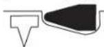
CTBaCe H3bnpa CnCTema 3a H3CTpeBAhe C
- Dopete 34pabo DO AetaaAa yAto13, pect. rympaHata npedna3HaCKo6a 10kato npednAa3HeAeT 3a H3CTpeAbaHeto 2 6bde HATNCHAT DOynop HABbTpE.
- CaeToba HATCHETe KpatKotpaHNo cncybKa 5 H ro OTHOBO r OTTYCHETe DO h3XoAHO TNOAOXeHne. NactpeAba Ce eHN KpeIeXeH eAEMENT.
-OTApbTHHeTe THeBMaTnHHH HnCTpyMeHT OT dTaHa.
-3a CEA BAAI IPOUC HA 3aBbAe HOTAEIe THeBMaTHHINHCTpyMeHT HAnbAHO OTIOBBxHOCTTA HaTeaHaNTOIOCTaBeTnIPHTCHETe KbM CEABAUOTOMRCTO, HA KOEt HOCKATE Da 3aBHeTE KpEteKeh EAMEHT.
Pa6ota c KOHTAKTHO H3CTpeAbaHe (BMXTeΦHr.D)
HaHTCHETeIpeBkAouBaTeA6HabTpE HcBueBpeMeHHo 3aBbPteTe AOropHaIO3nua,DOkATOce3axBaHeCIpewpaKaBaHe.
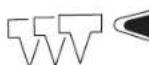

CTOBaCe H36npa CnCTema 3a H3CTpeBAHe C K0HTaKTHO 3aDeIcTBaHe.
HATNCHEtCnTycbKa5nro3a4pbkTeHaTCHaT.
- Doppte 34pabo DO AeTAA dyAOTo 13, pect. rympaHata PpeTn3HaCKoba 1DOKATO TpeTn3HTA 3a H3CTpeBAHeto 2 b6De HAChat DOynop HABbTe.
NCTpeBa ce eHNKpenkexeEemaEMT.
-OTApBTHETe THEBMATMHHH HHTCPyMeHT OT ATeaAa.
-3a CEA BAAI IPOUcE Ha 3aBbAe H0TAELe THeBMaTHHm HnCTpyMeHT HAIBHOOTIOBbPxHOCTTaHaTeAaHTOIOCTaBeTe INpHTNCHETe KbM CEABAWTO MRCTO,Ha KOEt HCKaTe Da 3aBHeKpeHexe EmeENT.
-Прнскайе ИОТддгпгпгпгпгпгпгпгпгпгпгпгпгпгпгпгпгпгпгпгпгпгпгпгпgнмHTbM IOBbpxHOCCTHa HTeaHnHa pa3AnuHm MeCTa. BceKN ITb, KORATO ПрнснстЕ NHcTpyMeHt DAocTaTbHO, Taka Ye IIpeIaIaIeIaIaIaIaIaIaIaIaIaIaIaIaIaIaIaIaIaIaIaIaIaIaIaIaIaIaIaIaIaIaIaIaIaIaIaIaIaIaIaIaIaIaIaIaIaIaIaIaIaIaIaa
Korato 3a6nHETe HxhHaTa 6pOka KpeTeXHn eAeMeHTn, OTYChTe CTyCbKa 5 Da HAaHOTo MY NOAOKeHHe.
Yka3aHHa 3pa60ta

IpeHdA ppoHHe HactpOKn, Da 3aMeHrte
Iphcno6eHH Hn DA OCTABTe THEBMATHHn
HhCTpMEnT, IpeKbCBAHTeIOAABAHEo HA Bb3Ax. Ta3i
IpeDHa3Ha MRAPKA IpeDTBpaTBA HeBOAHOTo BKHOUbaHe
Ha THEBMaTHuHn IHCTpMEnT.
BnHaHnped3aOuBaHe Ha pa6oTa npOBepBaIte 6ezykopHOTO
fynKluHnHpaHe HcCTeMeTHe 3a 6e0NaCHoc T 3a 3cTepeBAhe N ce
yBepBaIte, Ye BCHKN BHTOBN CbeDHeHnca 3aTeRHaTI.
Ako yctahOBHTE NOBpea Hn HnnpabHNO FyHKUHOHPaHE Ha HnKoIOT eLEMEHTNE, He3a6aBH0 OTaEAE TEHEBMATYHHN HNCTpyMeHT OT CNTcEMATA 3a CFbCTEH Bb3dYx N Ce 06bPheTe KMB OTOpHNpaH cepBN3 a EeKTPONHCTpyMeHTn Ha Boi.
He 3BbpaBaIte No THeBMaTHuHn HNCTpyMeHT DeHHoCTH, KOHO He ca OTmCaH N CbOTBeHTHe NHCtpyKun. He DEMOHTPaHTe H He 6LoKpAte DeTAAH Na THeBMaTHuHn HNCTpyMeHT, KaTO HaIP. PpeTa3HTeA 3a H3CTpeBAHeto.
HeI3BbPwBaIte(peMoHTH DeHOCTH)C HeIOxOaIu CpeAcTBA.
PiEBMaTHUHNHT HcTpyMeNT TpR6Ba Da 6BaDe OcbayKaH peAOBHO
Cb6pa3HO INCTpyKUInTe (BnXTe(PiOaDbPkAne HIOuNCTBaHe),
ctpaHua 161).
N36gBaTBeBCKAKBOyBpeXaHeHaIpeDnA3HneFyHKUHN HTHEBMAtuHHHINCTpymENT HINIOBpeDuNHO Hero,Harp.:
-uple3BbBaHeHnIraBnPaHpe,
- HETIpeBnAeHOOTIPOIN3BOAMTEA N3MeHeHHe HA KOHCTpyKlurTa,
-ITN BODHe IIO WbALOHN, KOHTO Ca HATpABeHH OT TBbpH MaTePHaH, HApD. CTOMaHa,
-NTYCKaHE HAN TAb3FaHE TO TIOa,
H3NIOA3BaHe KaTo 4yK,
-BCRAKBO CNAOBO Bb3AeHCTBNE.
BHHaH INPOBepBaJIte KaKBO CE HAmHPa IOA HAN 3aD o6paObTaBHn AETaI. He B6NBaHTe KpEeXHN eAEMeHTN BCTEH, TaBaHN HAN IIODOBe, Ako 3aT TIX HMA Xopa.KpeTeKHNTE eAEMeHTN MOrAT Da TIN IIObHIT N DA HapAHIT HAKOTO.
He h3ctpeBaBte KpEeKHN eAeEMHn BbPxy Aypyr KpEeKHN eAeMeHTN. Bb3MOxHO e KpEeKHNRT eAeMEnT Da ce DeOpMnPa, Aa Ce 3aKAHN H THeBMATNUHIN HNCTpyMeHT Nn THeBMATNUHIN HNCTpyMeHT Da oTCKOHN HEKOHTPoHPyEMO.
Ako THeBMaTHHHT HHTpyMeT CE 3NIO3BA IIPI HNCK OKOHA
TEMHPePATy, IIpBNTe KpTeXHH eAEMeHTI CE 3a6NBAT IO-6aBOOOT
0bHuAHOto. CAE 3aqrpaBaHTo HA THeBMaTHHn HHTpyMeT IIO BpeMe
Ha pa6ota OTHOBO CTABA Bb3MOxEH HOPMaHHT PHTbM Ha pa6ota.
3aHaH36eHTHeTpeXeBpeMeHHOTo H3HOCBaHE HaTaackaHa, H36raBaIte 4aTpeAaH3BbKBeT H3CTpeAeB6eTIOCTABEH CkO6n HAn TIPoHN.
PnPiPOdaXaKHeIHO pkeKcBaHa He pa6oTa Hn PpHnPKuOyBaHe OTDAJIeTIEHEBMATNUHHNHCPTPMENTOTCNCETMa3aCBCTEHB3dYx.
H3npa3BaHe Ha Mara3HHa (BHXTe pHyprn E1-E2)
I3aBpTnAte Ha3aTlAaCKaUHa MaRa3Hb11C Htncat TIOaBaMEXaHn3bM 18,DOkATO IOaBaAunr MEXaHn3bM OCBO6OHNOCAEHNKpeTExeH EMeENT, IN CLETO BA BHNMaTeHO OTTYChETe TAAckaHa Mara3HnHa HnpeAdIO ppeHnKpHnHa Mara3HnHa 10.
YbTaBHe: PnTOBa HcOyckaHTe TaCKaHT Ha Mara3Ha Da Ce BbPHe TIOA DeHCTBnETo H aPpyXHHATAo KpaHIO TIOAOKeHne, 6e3 Da 3axBaHe AETATa C INPOHN. TaKa TAAckauT MoKe Da c ToBpeHn CbIeCTByBa ONaCHOCT Da IpeuHNT ppctHTE Bn.
-3aBbPTe THeBMaTHHn HcTpyMeHT, TaKa Ye KpeTeKhIte eAEMeHTN B Ma3Ha Da Ce Nb3HaT Ha3aD0 PPyxHnTa 17.
-ПИТСНЕТРУЖИHAТАИОCTABETe KPEREXHHTE ELEMENTA CE TБЗHATIOKPаIPODABaUIMMEXAHN3bM 18 HABbOT MAra3HnA 10.
HactpoBaHe Ha dbA6OuHHnOrpaHmHTeA(BHXTeΦhrypaF)
AaBbOuHnata Ha 3a6BaHe Ha TINPOHnTE MoXe Da 6bDepeyHnpHa C BpTnIe Ce 6yToH 12.
AkoTHeBMaTHHHTNHTCPMENTHMAda6bdeH3nO3BaH TPoDbAIXTEHO BPEMe,IOKpHNEDEtAHNTeOT CTOMHa C TbBbK CAOH MaWHHO MACAO.ToBAIpeDToBpaTRBA KOpOAnpaHETO HM.
IopdbpxaHe n cepBn3
TIOAdbpXaHe HIOuHCTBaHe

IpeHdA IpOMeHrTe HAcTPOKH, Da 3aMeHrTe
IpcnocO6aEHN HA DA OCTABTe THeBMATHHN
HhCTPmEHT, IpeKcbAte IIOdaBAHTo HA Bb3Ax. Ta3H
IpeJa3Ha MRPKa IpeD0BpaTbBA HeBOAHO To BKAIOuBaHe
Ha THEBMAtuHn HhCTPmEHT.
Ako BbIpeKINIpeuH3HOTIO pOHN3BOCTBO HBNMaTeAHO N3ITBAHe Bb3HNHE IOBpea, peMOHTB TPRBa Da CE N3BbpN0T OTOpN3HpaCepBn3a INHCTpyMeHTNa Ha Boi.
BHHaH, KORato ce 06pbuatae KbM IpeAdCTaBHTeAte Ha BOW C BbIPOCH, MOA HENPeMeHHIO TOCOVAHTe 10-uaPpeHHa KATAoXeH HOMep, nTINCAH HA TaBeAkATA Ha THEBMaTHUHNHcTpymENT.
AnyckaTeXHHueKToO6cayXbaHeHpeMOHTbTa6bDat H3BpWBAHcMoO KBAaHnHnPaHnTexHnC ToBa ce rapaH Tnpa,ue CHpyHOCTTHaTHEBMaTHnHnHTNCHpyMeHTIe 6bDe 3ana3eHa.
BbIrapckn | 161
Ta3n DeHIOCTMOKe Da 6b4e H3bAHEHa 6bP30 H KaueCTBeHO BOTOpn3npaH CepBn3a HHTCPyMeHTn Ha BoII.
Cma3baHe HnHEBMaTHMnHnCTpyMeHT (BHXTeΦnJ)
AkoTINHEBMATNUHHT INCHPTPYMHT He E BKAIOUeH KbM KOMbHNpaH npda3eH peayuHP-BENTHA,TOI Tp8Ba TEPNOAHHOa 6bde CMA3BaH:
- PnAeKo HatoBapBaHe BeaHbXdHeBHO.
-ПиТExKoHATOBaBaHEBaTbTHAHeBHO.
TIIaH 3a TexHnuecko 06cayxkBaHe
IIOaBpKaIteOTbopa3aHxOaIuINBaB3Axy4,IpeIa3HTeA2NcTycbKa 5nCTn(npax,CTpyKKnTBCkNdP.I).
TouctBaTepeoBHO mara3nHa 10. OctpaHraBte TAACTMacOBHnn AdbpeHN CTpykKn, KOITMO MOrat Da CE HATpyTN BHERIO NBOpe Ha pa6ota.
KaTHETe 2-3 KaTHMaunHHMO MacAO Buyepa8.He DoabAHTe TBbpae MHOROMaunHHoMACAO,TbKATO CE Cb6npaBTHEBMATHIN HCHTPMeHTNCEHXBpIpe3OTBOPa3N3XODAUNH B34xY4.
H3noA3BaIe CaMO CMA3OHN MATEPHaAN, PIPENOPBuaHn OT BOW.
- MmhepaHOMOTOPHO MacAo SAE 10 (3aTnA3BaHe pH MNHO HNCKNOKOAHN TEMepaTyPi)
-MHepaHO MOTOPHO MCAO SAE 20
I3XbpaHHTe CMA3OHH NTOUHCTBaun INPepaaptn No HauHH, KOHTo He 3aMbpCRBA OKOAHA TcpeDa. Cta3BaHTe 3akoHOBHTe pa3TOpE6H.
IIOHCTBaTe TINHEBMATUHHN HNCTpyMeHT PeAOBHO, KATO ITOPOAxyBATE CbC CTCTEH Bb3AYX.
Senior Vice President
Head of Product
Engineering
Certification
Paa.
Robert Bosch GmbH, Power Tools Division
D-70745 Leinfelden-Echterdingen
Senior Vice President Head of Product
Engineering Certification

v( x,y) = ( x^ ,2)
Robert Bosch GmbH, Power Tools Division D-70745 Leinfelden-Echterdingen
Senior Vice President Head of Product
Engineering Certification
Robert Bosch GmbH, Power Tools Division
D-70745 Leinfelden-Echterdingen
Senior Vice President Head of Product
Engineering Certification

N 为 AQOG 垂
Robert Bosch GmbH, Power Tools Division
D-70745 Leinfelden-Echterdingen
Senior Vice President
Head of Product
Engineering
Certification

Robert Bosch GmbH, Power Tools Division
D-70745 Leinfelden-Echterdingen
Gaisa padeve (attels A)
Pärliecinieties, ka spiediens gaisa spiedientkla nav lielaks par
pneimatiska instrumenta maksimalo pielaujamo spiedienu. Pirms darba
ieregulejiet tadu gaisa spiedienu, kas atbilst ieteicamà nominalä
spiediena zemakajai robezvertebai (skatit sadalu „Tehniskie parametri").
Senior Vice President Head of Product
Engineering Certification
Pae Meae 1. Nocyc
Robert Bosch GmbH, Power Tools Division
D-70745 Leinfelden-Echterdingen
yolal ylll llll lllllllllllllllll
y 1
15
M
(..)
2b - a = 0
| الإستعمال | الإستعمال | الإستعمال |
| الإستعمال | الإستعمال | الإستعمال |
| الإستعمال | الإستnzients | الإستnzients |
| (208 مposium, "الإستnzients" ) | (208 مposium, "الإستnzients" ) | (208 مposium, "الإستnzients" ) |
| .الإستnzients | .الإستnzients | .11 000 000 000 000 000 000 000 000 000 000 000 000 000 000 000 000 000 000 000 000 000 000 000 000 000 00 |
| .الإستnzients | .الإستnzients | .11 000 000 000 000 000 000 000 000 000 000 000 000 000 000 000 000 000 000 000 000 1000 |
| .8 000 000 000 000 000 000 000 000 000 000 000 000 000 000 000 000 000 000 000 000 000 000 000 000 00 | .11 000 000 000 000 000 000 000 000 000 000 000 000 000 000 000 000 000 000 000 000 000 000 000 00 | .110000000000000000000000000000000000000000000000000000000000000000000000000000000000000000000000000000 |
| .125 000 000 000 000 000 000 000 000 000 000 000 000 000 000 000 000 000 000 000 000 000 000 000 000 00 | .125 000 000 000 000 000 000 000 000 000 000 000 000 000 000 000 000 000 000 000 000 000 000 000 0 |
jjj_1
| (208)الإستعمالالله胱مي – محيى الحرفية – محيى الحرفية – محيى الحرفية – محيى – محيى – محيى – محيى – محيى – محيى – محيى – محيى – محيى – محيى – محيى – محيى – محيى – محيى – محيى – محيى – محيى – محيى – محيى – محيى – محيى – محيى – محيى – محيى – محيى – محيioned – محيى – محيى – محيى – محيى – محيى – محيى – محيى – محيى – محيى – محيى – محيى – محيى – محيى – محيى – محيى – محيى – محيى – محيى – محيى – محيى – محيى – محيى – محيى – محيى – محيENSION – محيENSION – محيENSION – محيENSION – محيENSION – محيENSION – محيENSION – محيENSION – محيENSION – محيENSION – محيENSION – محيENSION – محيENSION – محيENSION – محيENSION – محيENSION – محيENSION – محيENSION – محيENSION – محيENSION – محيENSION – محيENSION – محيENSION – محيENSION – محيENSION – محيTION – محيTION – محيTION – محيTION – محيTION – محيTION – محيTION – محيTION – محيTION – محيTION – محيTION – محيTION – محيTION – محيTION – محيTION – محيTION – محيTION – محيTION – محيTION – محيTION – محيTION – محيTION – محيTION – محيTION – محيTION – محيENSION – محيENSION – محيENSION – محيENSION – محيENSION – محيENSION – محيENSION – محيENSION – محيENSION – محيENSION – محيENSION – محيENSION – محيENSION – محيENSION – محيENSION – محيENSION – محيENSION – محيENSION – محيENSION – محيENSION – محيENSION – محيENSION – محيENSION – محيENSION – محيRATION – محيRATION – محيRATION – محيRATION – محيRATION – محيRATION – محيRATION – محيRATION – محيRATION – محيRATION – محيRATION – محيRATION – محيRATION – محيRATION – محيRATION – محيRATION – محيRATION – محيRATION – محيRATION – محيRATION – محيRATION – محيRATION – محيRATION – محيRATION – محيRATION – محيENSION – محيENSION – محيENSION – محيENSION – محيENSION – محيENSION – محيENSION – محيENSION – محيENSION – محيENSION – محيENSION – محيENSION – محيENSION – محيENSION – محيENSION – محيENSION – محيENSION – محيENSION – محيENSION – محيENSION – محيENSION – محيENSION – محيENSION – محيENSION – محيINDER – محيINDER – محيINDER – محيINDER – محيINDER – محيINDER – محيINDER – محيINDER – محيINDER – محيINDER – محيINDER – محيINDER – محيINDER – محيINDER – محيINDER – محيINDER – محيINDER – محيINDER – محيINDER – محيINDER – محيINDER – محيINDER – محيINDER – محيINDER – محيINDER – محيKER – محيKER – محيKER – محيKER – محيKER – محيKER – محيKER – محيKER – محيKER – محيKER – محيKER – محيKER – محيKER – محيKER – محيKER – محيKER – محيKER – محيKER – محيKER – محيKER – محيKER – محيKER – محيKER – محيKER – محيKER – محيAKER – محيKER – محيKER – محيKER – محيKER – محيKER – محيKER – محيKER – محيKER – محيKER – محيKER – محيKER – محيKER – محيKER – محيKER – محيKER – محيKER – محيKER – محيKER – محيKER – محيKER – محيKER – محيKER – محيKER – محيKER – محيker – محيKER – محيKER – محيKER – محيKER – محيKER – محيKER – محيKER – محيKER – محيKER – محيKER – محيKER – محيKER – محيKER – محيKER – محيKER – محيKER – محيKER – محيKER – محيKER – محيKER – محيKER – محيKER – محيKER – محيKER – محيKR – محيKER – محيKER – محيKER – محيKER – محيKER – محيKER – محيKER – محيKER – محيKER – محيKER – محيKER – محيKER – محيKER – محيKER – محيKER – محيKER – محيKER – محيKER – محيKER – محيKER – محيKER – محيKER – محيKER – محيKER – محيKC – محيKER – محيKER – محيKER – محيKER – محيKER – محيKER – محيKER – محيKER – محيKER – محيKER – محيKER – محيKER – محيKER – محيKER – محيKER – محيKER – محيKER – محيKER – محيKER – محيKER – محيKER – محيKER – محيKER – محيKER – محيKO – محيKER – محيKER – محيKER – محيKER – محيKER – محيKER – محيKER – محيKER – محيKER – محيKER – محيKER – محيKER – محيKER – محيKER – محيKER – محيKER – محيKER – محيKER – محيKER – محيKER – محيKER – محيKER – محيKER – محيKER – محي*K – محيKER – محيKER – محيKER – محيKER – محيKER – محيKER – محيKER – محيKER – محيKER – محيKER – محيKER – محيKER – محيKER – محيKER – محيKER – محيKER – محيKER – محيKER – محيKER – محيKER – محيKER – محيKER – محيKER – محيKER – محيTER – محيKER – محيKER – محيKER – محيKER – محيKER – محيKER – محيKER – محيKER – محيKER – محيKER – محيKER – محيKER – محيKER – محيKER – محيKER – محيKER – محيKER – محيKER – محيKER – محيKER – محيKER – محيKER – محيKER – محيKER – محيKEN – محيKER – محيKER – محيKER – محيKER – محيKER – محيKER – محيKER – محيKER – محيKER – محيKER – محيKER – محيKER – محيKER – محيKER – محيKER – محيKER – محيKER – محيKER – محيKER – محيKER – محيKER – محيKER – محيKER – محيKER – محيCTOR – محيKER – محيKER – محيKER – محيKER – محيKER – محيKER – محيKER – محيKER – محيKER – محيKER – محيKER – محيKER – محيKER – محيKER – محيKER – محيKER – محيKER – محيKER – محيKER – محيKER – محيKER – محيKER – محيKER – محيKER – محيZE – محيKER – محيKER – محيKER – محيKER – محيKER – محيKER – محيKER – محيKER – محيKER – محيKER – محيKER – محيKER – محيKER – محيKER – محيKER – محيKER – محيKER – محيKER – محيKER – محيKER – محيKER – محيKER – محيKER – محيKER – محيK – محيKER – محيKER – محيKER – محيKER – محيKER – محيKER – محيKER – محيKER – محيKER – محيKER – محيKER – محيKER – محيKER – محيKER – محيKER – محيKER – محيKER – محيKER – محيKER – محيKER – محيKER – محيKER – محيKER – محيKER – محيITED – محيKER – محيKER – محيKER – محيKER – محيKER – محيKER – محيKER – محيKER – محيKER – محيKER – محيKER – محيKER – محيKER – محيKER – محيKER – محيKER – محيKER – محيKER – محيKER – محيKER – محيKER – محيKER – محيKER – محيKER – محي钵 – محيKER – محيKER – محيKER – محيKER – محيKER – محيKER – محيKER – محيKER – محيKER – محيKER – محيKER – محيKER – محيKER – محيKER – محيKER – محيKER – محيKER – محيKER – محيKER – محيKER – محيKER – محيKER – محيKER – محيKER – محيDER – محيKER – محيKER – محيKER – محيKER – محيKER – محيKER – محيKER – محيKER – محيKER – محيKER – محيKER – محيKER – محيKER – محيKER – محيKER – محيKER – محيKER – محيKER – محيKER – محيKER – محيKER – محيKER – محيKER – محيKER – محيKD – محيKER – محيKER – محيKER – محيKER – محيKER – محيKER – محيKER – محيKER – محيKER – محيKER – محيKER – محيKER – محيKER – محيKER – محيKER – محيKER – محيKER – محيKER – محيKER – محيKER – محيKER – محيKER – محيKER – محيKER – محيDED – محيKER – محيKER – محيKER – محيKER – محيKER – محيKER – محيKER – محيKER – محيKER – محيKER – محيKER – محيKER – محيKER – محيKER – محيKER – محيKER – محيKER – محيKER – محيKER – محيKER – محيKER – محيKER – محيKER – محيKER – محيKT – محيKER – محيKER – محيKER – محيKER – محيKER – محيKER – محيKER – محيKER – محيKER – محيKER – محيKER – محيKER – محيKER – محيKER – محيKER – محيKER – محيKER – محيKER – محيKER – محيKER – محيKER – محيKER – محيKER – محيKER – محيKE – محيKER – محيKER – محيKER – محيKER – محيKER – محيKER – محيKER – محيKER – محيKER – محيKER – محيKER – محيKER – محيKER – محيKER – محيKER – محيKER – محيKER – محيKER – محيKER – محيKER – محيKER – محيKER – محيKER – محيKER – محيKS – محيKER – محيKER – محيKER – محيKER – محيKER – محيKER – محيKER – محيKER – محيKER – محيKER – محيKER – محيKER – محيKER – محيKER – محيKER – محيKER – محيKER – محيKER – محيKER – محيKER – محيKER – محيKER – محيKER – محيKER – محيGER – محيKER – محيKER – محيKER – محيKER – محيKER – محيKER – محيKER – محيKER – محيKER – محيKER – محيKER – محيKER – محيKER – محيKER – محيKER – محيKER – محيKER – محيKER – محيKER – محيKER – محيKER – محيKER – محيKER – محيKER – محيINDER – محيKER – محيKER – محيKER – محيKER – محيKER – محيKER – محيKER – محيKER – محيKER – محيKER – محيKER – محيKER – محيKER – محيKER – محيKER – محيKER – محيKER – محيKER – محيKER – محيKER – محيKER – محيKER – محيKER – محيAKER – محيAKER – محيKER – محيKER – محيKER – محيKER – محيKER – محيKER – محيKER – محيKER – مúdeل –مstile –مstile –مstile –مstile –مstile –مstile –مstile –مstile –مstile –مstile –مstile –مstile –مstile –مstile –مstile –مstile –مstile –مstile –مstile –مstile –مstile –مstile –مstile –مstile –مstile –مstile –مstile –مstile –مstile –مstile –مstile –مstile –مstile –مstile -مstile -مstile -مstile -مstile -مstile -مstile -مstile -مstile -مstile -مstile -مstile -مstile -مstile -مstile -مstile -مstile -مstile -مstile -مstile -مstile -مstile -مstile -مstile -مstile -مstile -مstile -مstile -مstile -مstile -مstile -مstile -مstile -مstile -mstile -mstile -mstile -mstile -mstile -mstile -mstile -mstile -mstile -mstile -mstile -mstile -mstile -mstile -mstile -mstile -mstile -mstile -mstile -mstile -mstile -mstile -mstile -mstile -mstile -mstile -mstile -mstile -mstile -mstile -mstile -mstile -mstile -mvale -مstile -مstile -مstile -مstile -مstile -مstile -مstile -مstile -مstile -مstile -مstile -مstile -مstile -مstile -مstile -مstile -مstile -مstile -مstile -مstile -مstile -مstile -مstile -مstile -مstile -مstile -مstile -مstile -مstile -mstile -mstile -mstile -mstile- mstile -مstile -مstile -مstile -مstile -mstile -mstile -mstile -mstile -mstile -mstile -mstile -mstile -mstile -mstile -mstile -mstile -mstile -mstile -mstile -mstile -mstile -mstile -mstile -mstile -mstile -mstile -mstile -mstile -mstile -mstile -mstile -mstile -mtile -mtile -mtile -mtile -mtile -mtile -mtile -mtile -mtile -mtile -mtile -mtile -mtile -mtile -mtile -mtile -mtile -mtile -mtile -mtile -mtile -mtile -mtile -mtile -mtile -mtile -mtile -mtile -mtile -mtile -mtile -mtile -mtile -mtile- mtile -mtile -mtile -mtile -mtile -mtile -mtile -mtile -mtile -mtile -mtile -mtile -mtile -mtile -mtile -mtile -mtile -mtile -mtile -mtile -mtile -mtile -mtile -mtile -mtile -mtile -mtile -mtile -mtile -mtile -mtile -mtile -mtile -m tile -mtile -mtile -mtile -mtile -mtile -mtile -mtile -mtile -mtile -mtile -mtile -mtile -mtile -mtile -mtile -mtile -mtile -mtile -mtile -mtile -mtile -mtile -mtile -mtile -mtile -mtile -mtile -mtile -mtile -mtile -mtile -mtile -mtile - . . . . . . . . . . . . . . . . . . . . . . . . . . . . . . . . . . . . . . . . . . . . . . . . . . . . . . . . . . . . . . . . . . . ; . . . . . . . . . . . . . . . . . . . . . . . . . . . . . . . . . . . . . . . . . . . . . . . . . . . . . . . . . . . . . . . . . . . . . . . . . . . . . . . . . . . . . . . . . . . . . . . . . . . - . - . - . - . - . - . - . - . - . - . - . - . - . - . - . - . - . - . - . - . . - . - . - . - . - . - . - . - . - . - . - . - . - . - . - . - . - . - . - . - . - - - - - - - - - - - - - - - - - - - - - - - - - - - - - - - - - - - - - - - - - - - - - - - - - - . - - - - - - - - - - - - - - - - - - - - - - - - - - - - - - - - - - - - - - - - - - - - - - - - - - . - - - - - - - - - - - - - - - - - - - - - - - - - - - - - - - - - - - - - - - - - - - - - - - - . - . . . . . . . . . . . . . . . . . . . . . . . . . . . . . . . . . . . . . . . . . . . . . . . . . . . . . . . . . . . . . . . . . . . . . . . . . . . . . . . . . . . . . . . . . . . . . . . . . . . . ? . . . . . . . . . . . . . . . . . . . . . . . . . . . . . . . . . . . . . . . . . . . . . . . . . . . . . . . . . . . . . . . . . . . . . . . . . . . . . . . . . . . . . . . . . . . . . . . . . . . ... . . . . . . . . . . . . . . . . . . . . . . . . . . . . . . . . . . . . . . . . . . . . . . . . . . . . . . . . . . . . . . . . . . . . . . . . . . . . . . . . . . . . . . . . . . . . . . . . . . . \text{。 } \text{ } \text{ } \text{ } \text{ } \text{ } \text{ } \text{ } \text{ } \text{ } \text{ } \text{ } \text{ } \text{ } \text{ } \text{ } \text{ } \text{ } \text{ } \text{ } \text{ } \text{ } \text{ } \text{ } \text{ } \text{ } \text{ } \text{ } \text{ } \text{ } \text{ } \text{ } \text{ } \text{ } \text{ } \text{ } \text{ } \text{ } \text{ } \text{ } \text{ } \text{ } \text{ } \text{ } \text{ } \text{ } \text{ } \text{ } \text{ } \text{ } \text{ } \text{ }\text{ }\text{ }\text{ }\text{ }\text{ }\text{ }\text{ }\text{ }\text{ }\text{ }\text{ }\text{ }\text{ }\text{ }\text{ }\text{ }\text{ }\text{ }\text{ }\text{ }\text{ }\text{ }\text{ }\text{ }\text{ }\text{ }\text{ }\text{ }\text{ }\text{ }\text{ }\text{ }\text{ }\ \text{ }\text{ }\text{ }\text{ }\text{ }\text{ }\text{ }\text{ }\text{ }\text{ }\text{ }\text{ }\text{ }\text{ }\text{ }\text{ }\text{ }\text{ }\text{ }\text{ }\text{ }\text{ }\text{ }\text{ }\text{ }\text{ }\text{ }\text{ }\text{ }\text{ }\text{ }\text{ }\text{ } \text{ }\text{ }\text{ }\text{ }\text{ }\text{ }\text{ }\text{ }\text{ }\text{ }\text{ }\text{ }\text{ }\text{ }\text{ }\text{ }\text{ }\text{ }\text{ }\text{ }\text{ }\text{ }\text{ }\text{ }\text{ }\text{ }\text{ }\text{ }\text{ }\text{ }\text{ }\text{ } \text{ } \text{ }\text{ }\text{ }\text{ }\text{ }\text{ }\text{ }\text{ }\text{ }\text{ }\text{ }\text{ }\text{ }\text{ }\text{ }\text{ }\text{ }\text{ }\text{ }\text{ }\text{ }\text{ }\text{ }\text{ }\text{ }\text{ }\text{ }\text{ }\text{ }\text{ }\text{\text{ }}\text{ }\text{ }\text{ }\text{ }\text{ }\text{ }\text{ }\text{ }\text{ }\text{ }\text{ }\text{ }\text{ }\text{ }\text{ }\text{ }\text{ }\text{ }\text{ }\text{ }\text{ }\text{ }\text{ }\text{ }\text{ }\text{ }\text{ }\text{ }\text{ }\text{ }\text{ }\text{ }\text{ } \text{ }\text{ }\text{ }\text{ }\text{ }\text{ }\text{ }\text{ }\text{ }\text{ }\text{ }\text{ }\text{ }\text{ }\text{ }\text{ }\text{ }\text{ }\text{ }\text{ }\text{ }\text{ }\text{ }\text{ }\text{ }\text{ }\text{ }\text{ }\text{ }\text{ }\text{ }\text{ }\text{ }\mathrm{ }\text{ }\text{ }\text{ }\text{ }\text{ }\text{ }\text{ }\text{ }\text{ }\text{ }\text{ }\text{ }\text{ }\text{ }\text{ }\text{ }\text{ }\text{ }\text{ }\text{ }\text{ }\text{ }\text{ }\text{ }\text{ }\text{ }\text{ }\text{ }\text{ }\text{ }\text{ }\text{ }\text{\text{ }}\text{ }\mathrm{ }\text{ }\text{ }\text{ }\text{ }\text{ }\text{ }\text{ }\text{ }\text{ }\text{ }\text{ }\text{ }\text{ }\text{ }\text{ }\text{ }\text{ }\text{ }\text{ }\text{ }\text{ }\text{ }\text{ }\text{ }\text{ }\text{ }\text{ }\text{ }\text{ }\text{ }\text{ }\mathrm{ }\text{\text{ }}\text{ }\mathrm{ }\text{ }\text{ }\text{ }\text{ }\text{ }\text{ }\text{ }\text{ }\text{ }\text{ }\text{ }\text{ }\text{ }\text{ }\text{ }\text{ }\text{ }\text{ }\text{ }\text{ }\text{ }\text{ }\text{ }\text{ }\text{ }\text{ }\text{ }\text{ }\text{\text{ }}\text{ }\mathrm{ }\text{\text{ }}\text{ }\mathrm{ }\text{ }\text{ }\text{ }\text{ }\text{ }\text{ }\text{ }\text{ }\text{ }\text{ }\text{ }\text{ }\text{ }\text{ }\text{ }\text{ }\text{ }\text{ }\text{ }\text{ }\text{ }\text{ }\text{ }\text{ }\text{ }\text{ }\text{ }\mathrm{ }\text{ }\text{ }\text{ }\text{ }\text{\text{ }}\text{ }\mathrm{ }\text{ }\text{ }\text{ }\text{ }\text{ }\text{ }\text{ }\text{ }\text{ }\text{ }\text{ }\text{ }\text{ }\text{ }\text{ }\text{ }\text{ }\text{ }\text{ }\text{ }\text{ }\text{ }\text{ }\text{ }\text{\text{ }}\text{ }\mathrm{ }\text{ }\text{ }\text{ }\text{ }\text{\text{ }}\text{ }\mathrm{ }\text{ }\text{ }\text{ }\text{ }\text{ }\text{ }\text{ }\text{ }\text{ }\text{ }\text{ }\text{ }\text{ }\text{ }\text{ }\text{ }\text{ }\text{ }\text{ }\text{ }\text{ }\text{ }\text{ }\mathrm{ }\text{ }\text{ }\text{ }\text{ }\text{ }\text{ }\text{ }\text{ }\text{\text{ }}\text{ }\mathrm{ }\text{ }\text{ }\text{ }\text{ }\text{ }\text{ }\text{ }\text{ }\text{ }\text{ }\text{ }\text{ }\text{ }\text{ }\text{ }\text{ }\text{ }\text{ }\text{ }\text{ }\text{\text{ }}\text{ }\mathrm{ }\text{ }\text{ }\text{ }\text{ }\text{ }\text{ }\text{ }\text{ }\text{\text{ }}\text{ }\mathrm{ }\text{ }\text{ }\text{ }\text{ }\text{ }\text{ }\text{ }\text{ }\text{ }\text{ }\text{ }\text{ }\text{ }\text{ }\text{ }\text{ }\text{ }\text{ }\text{ }\mathrm{ }\text{ }\text{ }\text{ }\text{ }\text{ }\text{ }\text{ }\text{ }\text{ }\text{ }\text{ }\text{ }\text{\text{ }}\text{ }\mathrm{ }\text{ }\text{ }\text{ }\text{ }\text{ }\text{ }\text{ }\text{ }\text{ }\text{ }\text{ }\text{ }\text{ }\text{ }\text{ }\text{ }\text{\text{ }}\text{ }\mathrm{ }\text{ }\text{ }\text{ }\text{ }\text{ }\text{ }\text{ }\text{ }\text{ }\text{ }\text{ }\text{ }\text{\text{ }}\text{ }\mathrm{ }\text{ }\text{ }\text{ }\text{ }\text{ }\text{ }\text{ }\text{ }\text{ }\text{ }\text{ }\text{ }\text{ }\text{ }\text{ }\mathrm{ }\text{ }\text{ }\text{ }\text{ }\text{ }\text{ }\text{ }\text{ }\text{ }\text{ }\text{ }\text{ }\text{ }\text{ }\text{ }\text{ }\text{\text{ }}\text{ }\mathrm{ }\text{ }\text{ }\text{ }\text{ }\text{ }\text{ }\text{ }\text{ }\text{ }\text{ }\text{ }\mathrm{ }\text{ }\text{ }\text{ }\text{ }\text{ }\text{ }\text{ }\text{ }\text{ }\text{ }\text{ }\text{ }\text{ }\text{ }\text{ }\text{ }\text{ }\text{ }\text{ }\text{ }\text{\text{ }}\text{ }\mathrm{ }\text{ }\text{ }\text{ }\text{ }\text{ }\text{ }\text{ }\mathrm{ }\text{ }\text{ }\text{ }\text{ }\text{ }\text{ }\text{ }\text{ }\text{ }\text{ }\text{ }\text{ }\text{ }\text{ }\text{ }\text{ }\text{ }\text{ }\text{ }\text{ }\text{ }\text{ }\text{ }\text{ }\text{\text{ }}\text{ }\mathrm{ }\text{ }\text{ }\text{ }\mathrm{\text{ }}\text{ }\mathrm{\text{ }}\text{ }\mathrm{\text{ }}\text{ }\mathrm{\text{ }}\text{ }\mathrm{\text{ }}\mathrm{\text{ }}\mathrm{\text{ }}\mathrm{\text{ }}\mathrm{\text{ }}\mathrm{\text{ }}\mathrm{\text{ }}\mathrm{\text{ }}\mathrm{\text{ }}\mathrm{\text{ }}\mathrm{\text{ }}\mathrm{\text{ }}\mathrm{\text{ }}\mathrm{\text{ }}\mathrm{\text{ }}\mathrm{\text{ }}\mathrm{\text{ }}\mathrm{\text{}}\mathrm{\text{}}\mathrm{\text{}}\mathrm{\text{}}\mathrm{\text{}}\mathrm{\text{}}\mathrm{\text{}}\mathrm{\text{}}\mathrm{\text{}}\mathrm{\text{}}\mathrm{\text{}}\mathrm{\text{}}\mathrm{\text{}}\mathrm{\text{}}\mathrm{\text{}}\mathrm{\text{}}\mathrm{\text{}}\mathrm{\text{}}\mathrm{\text{}}\mathrm{\text{}}\mathrm{\text{}} \) - - - - - - - - - - - - - - - - - - - - - - - - - - - - - - - - - - - - - - - - - - - - - - - - - - |
| (H)g###lllglj#j alglg#lglj#j alglg#lglj#j alglg#lglj#j alglg#lglj#j alglg#lglj#j alglg#lglj#j alglg#lglj#j alglg#lglj#j alglg#lglj#j alglg#lglj#j alglg #j alglg #j alglg #j alglg #j alglg #j alglg #j alglg #j alglg #j alglg #j alglg #j alglg #j alglg #j alglg #j alglg #j alglg #j alglg #j alglg #j algtg #j alglg #j alglg #j alglg #j alglg #j alglg #j alglg #j alglg #j alglg #j alglg #j alglg #j alglg #j alglg #j alglg #j alglg #j alglg #j alglg #j |
| (E1-E2)### |
| 18 jujuy ### jujuy ### jujuy ### jujuy ### jujuy ### jujuy ### jujuy ### jujuy ### jujuy ### jujuy ### jujuy ### jujuy ### jujuy ### jujuy ### jujuy ### jujuy ### jujuy ### jujuy ### jujuy ### jujuy ### jujuy ### jujuy ### jujuy ### jujuy ### jujuy ### jujuy #jujuy ### jujuy ### jujuy ### jujuy ### jujuy ### jujuy ### jujuy ### jujuy ### jujuy ### jujuy ### jujuy ### jujuy ### jujuy ### jujuy ### jujuy ### jujuy ### jujuy ### jujuy ### jujuy ### jujuy ### jujuy ### jujuy ### jujuy ### jujuy ### jujuy ### |
| 10 ### jujuy ### jujuy ### jujuy ### jujuy ### jujuy ### jujuy ### jujuy ### jujuy ### jujuy ### jujuy ### jujuy ### jujuy ### jujuy ### jujuy ### jujuy ### jujuy ### jujuy ### jujuy ### jujuy ### jujuy ### jujuy ### jujuy ### jujuy ### jujuy ### jujury ### jujuy ### jujuy ### jujuy ### jujuy ### jujuy ### jujuy ### jujuy ### jujuy ### jujuy ### jujuy ### jujuy ### jujuy ### jujuy ### jujuy ### jujuy ### jujuy ### jujuy ### jujuy ### jujuy ### jujuy ### jujuy ### jujuy ### jujuy ### jujuy ### jujty ### jujuy ### jujuy ### jujuy ### jujuy ### jujuy ### jujuy ### jujuy ### jujuy ### jujuy ### jujuy ### jujuy ### jujuy ### jujuy ### jujuy ### jujuy ### jujuy ### jujuy ### jujuy ### jujuy ### jujuy ### jujuy ### jujuy ### jujuy ### jujuy ### jujuty ### jujuy ### jujuy ### jujuy ### jujuy ### jujuy ### jujuy ### jujuy ### jujuy ### jujuy ### jujuy ### jujuy ### jujuy ### jujuy ### jujuy ### jujuy ### jujuy ### jujuy ### jujuy ### jujuy ### jujuy ### jujuy ### jujuy ### jujuy ### jujuy ### jujy ### jujuy ### jujuy ### jujuy ### jujuy ### jujuy ### jujuy ### jujuy ### jujuy ### jujuy ### jujuy ### jujuy ### jujuy ### jujuy ### jujuy ### jujuy ### jujuy ### jujuy ### jujuy ### jujuy ### jujuy ### jujuy ### jujuy ### jujuy ### jujuy ### jujry ### jujuy ### jujuy ### jujuy ### jujuy ### jujuy ### jujuy ### jujuy ### jujuy ### jujuy ### jujuy ### jujuy ### jujuy ### jujuy ### jujuy ### jujuy ### jujuy ### jujuy ### jujuy ### jujuy ### jujuy ### jujuy ### jujuy ### jujuy ### jujuy ### jujdy ### jujdy ### jujdy ### jujdy ### jujdy ### jujdy ### jujdy ### jujdy ### jujdy ### jujdy ### jujdy ### jujdy ### jujdy ### jujdy ### jujdy ### jujdy ### jujdy ### jujdy ### jujdy ### jujdy ### jujdy ### jujdy ### jujdy ### jujdy ### jujdy ### jujty ### jujty ### jujty ### jujty ### jujty ### jujty ### jujty ### jujty ### jujty ### jujty ### jujty ### jujty ### jujty ### jujty ### jujty ### jujty ### jujty ### jujty ### jujty ### jujty ### jujty ### jujty ### jujty ### jujty ### jujty ### jujdy ### jujdy ### jujdy ### jujdy ### jujdy ### jujdy ### jujdy ### jujdy ### jujdy ### jujdy ### jujdy ### jujdy ### jujdy ### jujdy ### jujdy ### jujdy ### jujdy ### jujdy ### jujdy ### jujdy ### jujdy ### jujdy ### jujdy ### jujdy ### jujday ### jujday ### jujday ### jujday ### jujday ### jujday ### jujday ### jujday ### jujday ### jujday ### jujday ### jujday ### jujday ### jujday ### jujday ### jujday ### jujday ### jujday ### jujday ### jujday ### jujday ### jujday ### jujday ### jujday ### jujday ### juj day ### jujday ### jujday ### jujday ### jujday ### jujday ### jujday ### jujday ### jujday ### jujday ### jujday ### jujday ### jujday ### jujday ### jujday ### jujday ### jujday ### jujday ### jujday ### jujday ### jujday ### jujday ### jujday ### jujday ### jujday ### jujdy ### jujday ### jujday ### jujday ### jujday ### jujday ### jujday ### jujday ### jujday ### jujday ### jujday ### jujday ### jujday ### jujday ### jujday ### jujday ### jujday ### jujday ### jujday ### jujday ### jujday ### jujday ### jujday ### jujday ### juj day ### juj day ### jujday ### jujday ### jujday ### jujday ### jujday ### jujday ### jujday ### jujday ### jujday ### jujday ### jujday ### jujday ### jujday ### jujday ### jujday ### jujday ### jujday ### jujday ### jujday ### jujday ### jujday ### jujday ### jujday ### juj day ### jujd y### jujday ### jujday ### jujday ### jujday ### jujday ### jujday ### jujday ### jujday ### jujday ### jujday ### jujday ### jujday ### jujday ### jujday ### jujday ### jujday ### jujday ### jujday ### jujday ### jujday ### jujday ### jujday ### jujday ### jujday ### jujday### jujday ### jujday ### jujday ### jujday ### jujday ### jujday ### jujday ### jujday ### jujday ### jujday ### jujday ### jujday ### jujday ### jujday ### jujday ### jujday ### jujday ### jujday ### jujday ### jujday ### jujday ### jujday ### jujday ### jujday ### juj day### jujday ### jujday ### jujday ### jujday ### jujday ### jujday ### jujday ### jujday ### jujday ### jujday ### jujday ### jujday ### jujday ### jujday ### jujday ### jujday ### jujday ### jujday ### jujday ### jujday ### jujday ### jujday ### jujday ### jujday ### jujd y### jujday ### jujday ### jujday ### jujday ### jujday ### jujday ### jujday ### jujday ### jujday ### jujday ### jujday ### jujday ### jujday ### jujday ### jujday ### jujday ### jujday ### jujday ### jujday ### jujday ### jujday ### jujday ### jujday ### jijday ### jijday ### jijday ### jijday ### jijday ### jijday ### jijday ### jijday ### jijday ### jijday ### jijday ### jijday ### jijday ### jijday ### jijday ### jijday ### jijday ### jijday ### jijday ### jijday ### jijday### jijday### jijday### jijday### jijday### jijday### jijday### jijday### jijday### jijday### jijday### jijday### jijday### jijday### jijday### jijday### jijday### jijday### jijday### jijday### jijday### jijday### jijday### jijday### jijday### jijday### jijday### jijday### jijday### jijday### jijday### jijday### jijday### jijday### jijday### jijday### jijday### jijday### jijday### jijday### jijday### jijday### jijday### jijday### jijday### jijday### jijday### jijday### jijday### jijday### jijday###jijday###jijday###jijday###jijday###jijday###jijday###jijday###jijday###jijday###jijday###jijday###jijday###jijday###jijday###jijday###jijday###jijday###jijday###jijday###jijday###jijday###jijday###jijday###jijday###jijday### jijday###jijday###jijday###jijday###jijday###jijday###jijday###jijday###jijday###jijday###jijday###jijday###jijday###jijday###jijday###jijday###jijday###jijday###jijday###jijday###jijday###jijday###jijday###jijday### |
aai
1
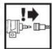
(Cjallj)j
1 6
1
13 2
5 5u
| x^ | = 1| x| · | r1^2 + r2^2 + r_3^2| ≤ 34| x| ^2
-
15
(Djgall j)
i 6
y

1b jzai 5i
1 13
JLSS 2.3N
S OBC = S COD + S BOC - S BOC
Jaiilai jai ge wjol baiaiy oaii peo
jaiy jaiy jaiy jaiy jaiy jaiy jaiy jaiy jaiy jaiy jaiy jaiy jaiy jaiy jaiy jaiy jaiy jaiy jaiy jaiy jaiy jaiy jaiy jaiy jaiy jaiy jaiy jaiy jaiy jaiy jaiy jaiy jaiy jaiy jaliy
Jnnn nn nnnn nn nnnnnnnnnnnnnnnnnnnnnnnnnnnnnnnnnnnnnnnnnnnnnnnnnnnnnnnnnnnnnnnnnnnnnnnnnnnnnnnnnnnnnnnnnnnnnnnnnnnnnnnnn
=
1 1
- a : S1 = 1 a^2 = 1 S2 = 1;S_3 = 2
a b 1 a 1 1 1 1 1 1 1 1 1 1 1 1 1 1 1 1 1
yllal laiil iaii jaii jaii jaii jaii jaii jaii jaii jaii jaii jaii jaii jaii jaii jaii jaii jaii jaii jaii jaii jaii jaii jaii jaii jaii jaii jaii jaii jaii jaii jaii jaii jaii jaii jali
14
g jai 10 gbiu u 10 guiu u
(208a)()10j
aaiy 1
aall
J
14 15 8
jaii jaii jaii jaii jaii jaii jaii jaii jaii jaii jaii jaii jaii jaii jaii jaii jaii jaii jaii jaii jaii jaii jaii jaii jaii jaii jaii jaii jaii jaii jaii jaii jaii jaii jali
sblbgl aolal 1 bai
y
(B1-B4jallj)jdllo
i 1
bgaalolgblae
S ACD = S COD + S_ BDO
suii i 1
y
1
b
1
13 10
1
10j j 11j j
10jT 16
y
yie b jaiai yai jaiy jaiy jaiy jaiy jaiy jaiy jaiy
ailllll llll y aiey
.
100 110000000000000000000000000000000000
Jus 10 jdai jy
y 1
1
18 123456789011234567890
a a
即 S APQ = S AOB + S_ OBC
000000000000000000000000000000000000000
a
J
3x+1 2x+1
y
30 2021 2021 2021
y 1. pLdy jaiid a 2 ybln u 5yjuiu ydy pla
5.5uJyIe JaiyIyIyIyIyIy
y
y
xu 1
5 15
- 2.
i 1
6 Jg 1
C∈
y
.2006/42/EGG
1
Robert Bosch GmbH, PT/ESC,
D-70745 Leinfelden-Echterdingen
Dr. Egbert Schneider Senior Vice President Engineering
Dr. Eckerhard Strögtgen
Head of Product Certification

Robert Bosch GmbH, Power Tools Division
D-70745 Leinfelden Echterdingen
22.03.2011
Jus Jus 1s jus 1s 1s 1s 1s 1s 1s 1s 1s 1s 1s 1s 1s 1s 1s 1s 1s 1s 1s 1s 1s 1s 1s 1s 1s 1s 1s 1s 1s 1s 1s 1s 1s 1s 1s
j 10000000000000000000000000000000000000000000000000
m = 311
p 1
bglal 1gbl jy

y 100000000000000000000000000000000000000000000000000000000000000
y
1g 1
y 11111111111111111111111111111111111111111111111

1g 1011111111111111111111111111

a 111111111111111111111111111
y
gaiyolglal 10000000000000000000000000000000000000000000000000000000000000000
#
1
b jai 1jai jai jai jai jai
y 1
A
S_ OBC = 12 · OB · BC = 12 × CD × 5
Jauu Jauu
JyI yIyIyIyIyIyIyIyIyIyIyIyIyIyIyIyIyIyIyIy
Jg 1
Jauuueaiee eae aee ae aee aee aee aee aee aee
10 : 21 ÷ 10 = 7( 8)
aaiy aaiy aaiy aaiy aaiy aaiy aaiy aaiy aaiy aaiy aaiy aaiy aaiy aaiy aaiy aaiy aaiy aaiy aaiy aaiy aaiy aaiy aaiy aaiy aaiy aaiy aaiy aaiy aaiy aaiy aaiy aaiy aaiy aaiy aal y
pblal 124 100 100 100 100 100 100 100 100 100 100 100 100 100 100 100 100 100 100 100 100 100 100 100 100 100 10
= 1
algl 10000000000000000000000000000000000000000000000000000000000
e 1
y 1
yj yj yj yj yj yj yj yj yj yj yj yj yj yj yj yj yj yj yj yj yj yj yj yj yj yj yj yj yj yj yj yj yj yj yj yj yj yj
y 1
Lalaiy 10000000000000000000000000000000000000000000000000000000000000000000
biidai 1ydi 2e pliuiu yiu
puee 10000000000000000000000000000000000000000000000000000000000000
| الله صَلُّة الحَلِيّة الحَلِيّة – (عَزَ وَدَعَلْهُ لَلَهُ وَالَسَنَبْرِ وَالَسَنَبْرِ وَالَسَنَبْرِ وَالَسَنَبْرِ وَالَسَنَبْرِ وَالَسَنَبْرِ وَالَسَنَبْرِ وَالَسَنَبْرِ وَالَسَنَبْرِ وَالْمَسَنَبْرِ وَالَسَنَبْرِ وَالَسَنَبْرِ وَالَسَنَبْرِ وَالَسَنَبْرِ وَالَسَنَبْرِ وَالَسَنَبْرِ وَالَسَنَبْرِ وَالَسَнَبْرِ وَالَسَنَبْرِ وَالَسَنَبْرِ وَالَسَنَبْرِ وَالَسَنَبْرِ وَالَسَنَبْرِ وَالَسَنَبْرِ وَالَسَنَبْرِ وَالَسَنَبْrْ وَالَسَنَبْrْ |
| الله صَلُّة الحَلِيّة الحَلِيّة – (عَزَ وَدَعَلْهُ لَلَهُ وَالَسَ�َنَبْرِ وَالَسَ�َنَبْرِ وَالَسَ�َنَبْرِ وَالَسَ�َنَبْrْ |
| الله صَلُّة الحَلِيّة – (عَزَ وَدَعَلْهُ لَلَهُ وَالَسَ�َنَبْرِ |
| الله صَلُّة – (عَزَ وَدَعَلْهُ) (عَزَ وَدَعَلْهُ) (عَزَ وَدَعَلْهُ) (عَزَ وَدَعَلْهُ) (عَزَ وَدَعَلْهُ) (عَزَ وَدَعَلْهُ) (عَزَ وَدَعَلْهُ) (عَrozَ وَدَعَلْهُ) (عَrozَ وَدَعَلْهُ) (عَrozَ وَدَعَلْهُ) (عَrozَ وَدَعَلْهُ) (عَrozَ وَدَعَلْهُ) (عَrozَ وَدَعَلْهُ) (عَrozَ وَdɪˈsʌtɪˈsʌtɪˈsʌtɪˈsʌtɪˈsʌtɪˈsʌtɪˈsʌtɪˈsʌtɪˈsʌtɪˈsʌtɪˈsʌtɪˈsʌtɪˈsʌtɪˈsʌtɪˈsʌtɪˈsʌtɪˈsʌtɪˈsʌtɪˈsʌtɪˈsʌtɪˈsʌ tɪˈsʌtɪˈsʌtɪˈsʌtɪˈsʌtɪˈsʌtɪˈsʌtɪˈsʌtɪˈsʌtɪˈsʌtɪˈsʌtɪˈsʌtɪˈsʌtɪˈsʌtɪˈsʌtɪˈsʌtɪˈsʌtɪˈsʌtɪˈsʌtɪˈsʌtɪˈsʌsʌtɪˈsʌtɪˈsʌtɪˈsʌtɪˈsʌtɪˈsʌtɪˈsʌtɪˈsʌtɪˈsʌtɪˈsʌtɪˈsʌtɪˈsʌtɪˈsʌtɪˈsʌtɪˈsʌtɪˈsʌtɪˈsʌtɪˈsʌtɪˈsʌtɪˈsʌtɪˌ |
| الله صَلُّة – (عَزَ وَdɪˈsʌtɪˈsʌtɪˈsʌtɪˈsʌtɪˈsʌtɪˈsʌtɪˈsʌtɪˈsʌtɪˈsʌtɪˈsʌtɪˈsʌtɪˈsʌtɪˈsʌtɪˈsʌtɪˈsʌtɪˈsʌtɪˈsʌtɪˈsʌtɪˈsʌt¹) |
| الله صَلُّة – (عَزَ وَdɪˈsʌtɪˈsʌtɪˈsʌtɪˈsʌtɪˈsʌtɪˈsʌtɪˈsʌtɪˈsʌtɪˈsʌtɪˈsʌtɪˈsʌtɪˈsʌtɪˈsʌtɪˈsʌtɪˈsʌtɪˈsɒ |
| الله صَلُّة – (عَزَ وَdɪˈsʌtɪˈsʌtɪˈsʌtɪˈsʌtɪˈsʌtɪˈsʌtɪˈsʌtɪˈsʌtɪˈsʌtɪˈsʌtɪˈsʌtɪˈsʌtɪˈsʌtɪˈsʌtɪˈsʌtɪˈsɑ |
| الله صَلُّة – (عَزَ وَdɪˈsʌtɪˈsʌtɪˈsʌtɪˈsʌtɪˈsʌtɪˈsʌtɪˈsʌtɪˈsʌtɪˈsʌtɪˈsʌtɪˈsʌtɪˈsʌtɪˈsʌtɪˈsʌtɪˈsʌtɪˈsə |
| الله صَلُّة – (عَزَ وَdɪˈsʌtɪˈsʌtɪˈsʌtɪˈsʌtɪˈsʌtɪˈsʌtɪˈsʌtɪˈsʌtɪˈsʌtɪˈsʌtɪˈsʌtɪˈsʌtɪˈsʌtɪˈsʌtɪˈsʌtɪˈsɔ |
| الله صَلُّة – (عَزَ وَdɪˈsʌtɪˈsʌtɪˈsʌtɪˈsʌtɪˈsʌtɪˈsʌtɪˈsʌtɪˈsʌtɪˈsʌtɪˈsʌtɪˈsʌtɪˈsʌtɪˈsʌtɪˈsʌtɪˈsʌtɪˈsæ |
| الله صَلُّة – (عَزَ وَdɪˈsʌtɪˈsʌtɪˈsʌtɪˈsʌtɪˈsʌtɪˈsʌtɪˈsʌtɪˈsʌtɪˈsʌtɪˈsʌtɪˈsʌtɪˈsʌtɪˈsʌtɪˈsʌtɪˈsʌtɪˈsø |
| الله صَلُّة – (عَزَ وَdɪˈsʌtɪˈsʌtɪˈsʌtɪˈsʌtɪˈsʌtɪˈsʌtɪˈsʌtɪˈsʌtɪˈsʌtɪˈsʌtɪˈsʌtɪˈsʌtɪˈsʌtɪˈsʌtɪˈsʌtɪˈs æ |
| الله صَلُّة – (عَزَ وَdɪˈsʌtɪˈsʌtɪˈsʌtɪˈsʌtɪˈsʌtɪˈsʌtɪˈsʌtɪˈsʌtɪˈsʌtɪˈsʌtɪˈsʌtɪˈsʌtɪˈsʌtɪˈsʌtɪˈsʌtɪˈsɚ |
| الله صَلُّة – (عَزَ وَdɪˈsʌtɪˈsʌtɪˈsʌtɪˈsʌtɪˈsʌtɪˈsʌtɪˈsʌtɪˈsʌtɪˈsʌtɪˈsʌtɪˈsʌtɪˈsʌtɪˈsʌtɪˈsʌtɪˈsʌtɪˈs・ |
| الله صَلُّة – (عَزَ وَdɪˈsʌtɪˈsʌtɪˈsʌtɪˈsʌtɪˈsʌtɪˈsʌtɪˈsʌtɪˈsʌtɪˈsʌtɪˈsʌtɪˈsʌtɪˈsʌtɪˈsʌtɪˈsʌtɪˈsʌtɪˈs• |
| الله صَلُّة – (عَزَ وَdɪˈsʌtɪˈsʌtɪˈsʌtɪˈsʌtɪˈsʌtɪˈsʌtɪˈsʌtɪˈsʌtɪˈsʌtɪˈsʌtɪˈsʌtɪˈsʌtɪˈsʌtɪˈsʌtɪˈsʌtɪˈs‐ |
| الله صَلُّة – (عَزَ وَdɪˈsʌtɪˈsʌtɪˈsʌtɪˈsʌtɪˈsʌtɪˈsʌtɪˈsʌtɪˈsʌtɪˈsʌtɪˈsʌtɪˈsʌtɪˈsʌtɪˈsʌtɪˈsʌtɪˈsʌtɪˈs⁻ |
| الله صَلُّة – (عَزَ وَdɪˈsʌtɪˈsʌtɪˈsʌtɪˈsʌtɪˈsʌtɪˈsʌtɪˈsʌtɪˈsʌtɪˈsʌtɪˈsʌtɪˈsʌtɪˈsʌtɪˈsʌtɪˈsʌtɪˈsʌtɪˈs・ |
| الله صَلُّة – (عَزَ وَdɪˈsʌtɪˈsʌtɪˈsʌtɪˈsʌtɪˈsʌtɪˈsʌtɪˈsʌtɪˈsʌtɪˈsʌtɪˈsʌtɪˈsʌtɪˈsʌtɪˈsʌtɪˈsʌtɪˈsʌtɪˈs· |
| الله صَلُّة – (عَزَ وَdɪˈsʌtɪˈsʌtɪˈsʌtɪˈsʌtɪˈsʌtɪˈsʌtɪˈsʌtɪˈsʌtɪˈsʌtɪˈsʌtɪˈsʌtɪˈsʌtɪˈsʌtɪˈsʌtɪˈsʌtɪˈs⋅ |
| الله صَلُّة – (عَزَ وَdɪˈsʌtɪˈsʌtɪˈsʌtɪˈsʌtɪˈsʌtɪˈsʌtɪˈsʌtɪˈsʌtɪˈsʌtɪˈsʌtɪˈsʌtɪˈsʌtɪˈsʌtɪˈsʌtɪˈsʌtɪˈs∼ |
| الله صَلُّة – (عَزَ وَdɪˈsʌtɪˈsʌtɪˈsʌtɪˈsʌtɪˈsʌtɪˈsʌtɪˈsʌtɪˈsʌtɪˈsʌtɪˈsʌtɪˈsʌtɪˈsʌtɪˈsʌtɪˈsʌtɪˈsʌtɪˈs▲ |
| الله صَلُّة – (عَزَ وَdɪˈsʌtɪˈsʌtɪˈsʌtɪˈsʌtɪˈsʌtɪˈsʌtɪˈsʌtɪˈsʌtɪˈsʌtɪˈsʌtɪˈsʌtɪˈsʌtɪˈsʌtɪˈsʌtɪˈsʌtɪˈs● |
| الله صَلُّة – (عَزَ وَdɪˈsʌtɪˈsʌtɪˈsʌtɪˈsʌtɪˈsʌtɪˈsʌtɪˈsʌtɪˈsʌtɪˈsʌtɪˈsʌtɪˈsʌtɪˈsʌtɪˈsʌtɪˈsʌtɪˈsʌtɪˈs◆ |
| الله صَلُّة – (عَزَ وَdɪˈsʌtɪˈsʌtɪˈsʌtɪˈsʌtɪˈsʌtɪˈsʌtɪˈsʌtɪˈsʌtɪˈsʌtɪˈsʌtɪˈsʌtɪˈsʌtɪˈsʌtɪˈsʌtɪˈsʌtɪˈs△ |
| الله صَلُّة – (عَزَ وَdɪˈsʌtɪˈsʌtɪˈsʌtɪˈsʌtɪˈsʌtɪˈsʌtɪˈsʌtɪˈsʌtɪˈsʌtɪˈsʌtɪˈsʌtɪˈsʌtɪˈsʌtɪˈsʌtɪˈsʌtɪˈs∆ |
| الله صَلُّة – (عَزَ وَdɪˈsʌtɪˈsʌtɪˈsʌtɪˈsʌtɪˈsʌtɪˈsʌtɪˈsʌtɪˈsʌtɪˈsʌtɪˈsʌtɪˈsʌtɪˈsʌtɪˈsʌtɪˈsʌtɪˈsʌtɪˈs∠ |
| الله صَلُّة – (عَزَ وَdɪˈsʌtɪˈsʌtɪˈsʌtɪˈsʌtɪˈsʌtɪˈsʌtɪˈsʌtɪˈsʌtɪˈsʌtɪˈsʌtɪˈsʌtɪˈsʌtɪˈsʌtɪˈsʌtɪˈsʌtɪˈs |
| الله صَلُّة – (عَزَ وَdɪˈsʌtɪˈsʌtɪˈsʌtɪˈsʌtɪˈsʌtɪˈsʌtɪˈsʌtɪˈsʌtɪˈsʌtɪˈsʌtɪˈsʌtɪˈsʌtɪˈsʌtɪˈsʌtɪˈsʌtɪˈs\( \text{一} \) |
| الله صَلُّة – (عَزَ وَdɪˈsʌtɪˈsʌtɪˈsʌtɪˈsʌtɪˈsʌtɪˈsʌtɪˈsʌtɪˈsʌtɪˈsʌtɪˈsʌtɪˈsʌtɪˈsʌtɪˈsʌtɪˈsʌtɪˈsʌtɪˈS A |
| الله صَلُّة – (عَزَ وَdɪˈsʌtɪˈsʌtɪˈsʌtɪˈsʌtɪˈsʌtɪˈsʌtɪˈsʌtɪˈsʌtɪˈsʌtɪˈsʌtɪˈsʌtɪˈsʌtɪˈsʌtɪˈsʌtɪˈsʌtɪˈs \( \text{一} \) |
| الله صَلُّة – (عَزَ وَdɪˈsʌtɪˈsʌtɪˈsʌtɪˈsʌtɪˈsʌtɪˈsʌtɪˈsʌtɪˈsʌtɪˈsʌtɪˈsʌtɪˈsʌtɪˈsʌtɪˈsʌtɪˈsʌtɪ \( \text{一} \) |
| الله صَلُّة – (عَزَ وَdɪˈsʌtɪˈsʌtɪˈsʌtɪˈsʌtɪˈsʌtɪˈsʌtɪˈsʌtɪˈsʌtɪˈsʌtɪˈsʌtɪˈsʌtɪˈsʌtɪˈsʌtɪˈsʌt¹) |
| الله صَلُّة – (عَزَ وَdɪˈsʌtɪ \( \text{一} \) |
| الله صَلُّة – (عَزَ وَdɪˈsʌtɪ \( \text{一} \) |
| الله صَلُّة – (عَزَ وَdɪˈsʌtɪ \( \text{一} \) |
| الله صَلُّة – (عَزَ وَdɪˈsʌtɪ \( ^{\prime \prime } \) |
| الله صَلُّة – (عَزَ وَdɪˈsʌtɪ \( ^{\prime \prime } \) |
| الله صَلُّة – (عَزَ وَdɪˈsʌtɪ \( ^{\prime \prime } \) |
| الله صَلُّة – (عَزَ وَdɪˈsʌstɪ \( ^{\prime \prime } \) |
| الله صَلُّة – (عَزَ وَdɪˈsʌtɪ \( ^{\prime \prime } \) |
| الله صَلُّة – (عَزَ وَdɪˈsʌtɪ \( ^{\prime \prime } \) |
| الله صَلُّة – (عَزِ وَdɪˈsʌtɪ \( ^{\prime \prime } \) |
| الله صَلُّة – (عَزَ وَdɪˈsʌtɪ \( ^{\prime \prime } \) |
| الله صَلُّة – (عَزَ وَdɪˈsʌtɪ \( ^{\prime \prime } \) |
| الله صَلُ� – (عَزَ وَdɪˈsʌtɪ \( ^{\prime \prime } \) |
| الله صَلُ� – (عَزَ وَdɪˈsʌtɪ \( ^{\prime \prime } \) |
| الله صَلُ� – (عَزَ وَdɪˈsʌtɪ \( ^{\prime \prime } \) |
| الfalls – (عَزَ وَdɪˈsʌtɪ \( ^{\prime \prime } \) |
| (عَزَ وَdɪˈsʌtɪ \( ^{\prime \prime } \) |
| (عَزَ وَdɪˈsʌtɪ \( ^{\prime \prime } \) |
| (عَزَ وَdɪˈsʌtɪ \( ^{\prime \prime } \) |
| (عَزَ وَdɪˈsʌtɪ \( ^{\prime \prime } 2 \) |
| (عَزَ وَdɪˈsʌtɪ \( ^{\prime \prime } \) |
| (عَزَ وَdɪˈsʌtɪ \( ^{\prime \prime } \) |
| (عَزَ وَdɪˈsʌtɪ \( ^{\prime \prime } \) |
| (عَزَ وَdɪˈsʌtɪ \( ^ {\prime \prime } \) |
| (عَزَ وَdɪˈsʌtɪ \( ^ {\prime \prime } \) |
| (عَزَ وَdɪˈsʌtɪ \( ^ {\prime \prime } \) |
| (عَزَ وَdɪˈsʌtɪ \( ^ {\prime \prime } \) |
| (عَزَ وَdɪˈsʌstɪ \( ^ {\prime \prime } \) |
| (عَزَ وَdɪˈsʌtɪ \( ^ {\prime \prime } \) |
| (عَزَ وَdɪˈsʌstɪ \( ^ {\prime \prime } \) |
| (عَزَ وَdɪˈsʌstɪ \( ^ {\prime \prime } \) |
| (عَزَ وَdɪˈsʌstɪ \( ^ {\prime \prime } \) |
| (عَزَ وَdɪˈsʌstɪ \( ^ {\prime \prime } \) |
| (عَزَ وَd—I \( ^{\prime \prime } \) |
| (عَزَ وَd—I \( ^{\prime \prime } \) |
| (عَزَ وَd—I \( ^{\prime \prime } \) |
| (عَزَ وَd—I \( ^{\prime \prime } \) |
| (عَزَ وَd—I \( ^{\prime \prime } \) |
| (عَزَ وِدْسْفْسْسْسْسْسْسْسْسْسْسْسْسْسْسْسْسْسْسْسْسْسْسْسْسْسْسْسْسْسْسْسْسْسْسْسْسْسْسْسْسْسْسْسْسْسْسْسْسْسْسْs |
| (عَزَ وَd—I \( ^{\prime \prime } \) |
| (عَزَ وَd—I \( ^{\prime \prime } \) |
| (عَزَ وَd—I \( ^{\prime \prime } \) |
| (عَزَ وَd—I \( ^{\prime \prime } \) |
| (عَزَ وَd—I \( ^{\mathrm{s}} \) |
| (عَزَ وَd—I \( ^{\prime \prime } \) |
| (عَزَ وَd—I \( ^{\prime \prime } \) |
| (عَزَ وَd—I \( ^{\prime \prime } \) |
| (عَزَ وَd—I \( ^{\prime \prime } \) |
| (عَزَ وَd—I \( \text{一} \) |
| (عَزَ وَd—I \( \text{一} \) |
| (عَزَ وَd—I \( \text{一} \) |
| (عَزَ وَd—I \( \text{一} \) |
| (عَزَ وَd—I \( \text{一} \) |
| (عَزَ وَd—I \( \text{一}\) |
| (عَزَ وَd—I \( \text{一} \) |
| (عَزَ وَd—I \( \text{一} \) |
| (عَزَ وَd—I \( \text{一} \) |
| (عَزَ وَd—I \( \text{一} \) |
| (عَزَ وَd—I \( \text{一} 2 \) |
| (عَزَ وَd—I \( \text{一} \) |
| (عَزَ وَd—I \( \text{一} \) |
| (عَزَ وَd—I \( \text{一} \) |
| (عَزَ وَd—I \( \text{一} \) |
| (عَزَ وَd—I \( \text{一}}} |
| (عَزَ وَd—I \( \text{一} \) |
| (عَزَ وَd—I \( \text{一} \) |
| (عَزَ وَd—I \( \text{一} \) |
| (عَزَ وَd—I \( \text{一} \) |
| (عَزَ وَd—I \( \text{一} \ ) |
| (عَزَ وَd—I \( \text{一} \) |
| (عَزَ وَd—I \( \text{一} \) |
| (عَزَ وَd—I \( \text{一} \) |
| (عَزَ وَd—I \( \text{一} \) |
| (عَزَ وَd—I \( \text{一} \)) |
| (عَزَ وَd—I \( \text{一} \) |
| (عَزَ وَd—I \( \text{一} \) |
| (عَزَ وَd—I \( \text{一} \) |
| (عَزَ وَd—I \( \text{一} \) |
| (عَزَ وَd—I \( \text{一} \)\( \text{一} \) |
| (عَزَ وَd—I \( \text{一} \) |
| (عَزَ وَd—I \( \text{一} \) |
| (عَزَ وَd—I \( \text{一} \) |
| (عَزَ وَd—I \( \text{一} \) |
| (عَزَ وَd—I\( \text{一} \) |
| (عَزَ وَd—I \( \text{一} \) |
| (عَزَ وَd—I \( \text{一} \) |
| (عَزَ وَd—I \( \text{一} \) |
| (عَزَ وَd—I \( \text{一} \) |
| (عَزَ وَd—I\) |
| (عَزَ وَd—I \( \text{一} \) |
| (عَزَ وَd—I \( \text{一} \) |
| (عَزَ وَd—I \( \text{一} \) |
| (عَزَ وَd—I \( \text{一} \) |
| (عَزَ وَd—I \( \text{一} \) (عَزَ وَd—I \( \text{一} \) |
| (عَزَ وَd—I \( \text{一} \) |
| (عَزَ وَd—I \( \text{一} \) |
| (عَزَ وَd—I \( \text{一} \) |
| (عَزَ وَd—I \( \text{一} \) |
= l0l0
JL 10000000000000000000000000000000000000000000000000000000000
JgLgLo g
e 1
www.bosch-pt.com
y 1000000000000000000000000000000000000000000000000000000000000
0e:2023
jI Cui jI aai 10000000000000000000000000000000000000000000000000000000000000000000000000000000000
g yjLwq gaiy jaiy jai 1gogg yjy jiy jiy jiy jiy jiy jiy jiy jiy jiy jiy jiy jiy jiy jiy jiy jiy jiy jiy jiy jiy jiy jiy jiy jiy jiy jiy jiy jiy jiy jiy jiy jiy jiy jiy jiy jiy jiy jiy jiy jiy jiy jiy jiy jiy jiy jiy jiy jiy jiy jiy juyi
j 1 j 1 j 1 j 1 j 1 j 1 j 1 j 1 j 1 j 1 j 1 j 1 j 1 j 1 j 1 j 1 j 1 j 1 j 1 j 1 j 1 j 1 j 1 j 1 j 1 j 1 j 1 j 1 j 1 j 1 j 1 j 1 j 1 j 1 j
J 1
()
-
-
-
-
-
-
-
-
-
-
-
-
-
-
-
-
-
-
-
-
-
-
-
-
-
-
-
-
-
-
-
-
-
-
-
-
-
-
-
-
-
-
-
-
-
-
-
-
-
-
-
-
-
-
-
-
-
-
-
-
-
-
-
-
-
-
-
-
-
-
-
-
-
-
- 76.
-
-
-
-
-
-
-
-
-
-
-
-
-
-
-
-
-
-
-
-
-
-
-
-
-
-
-
-
-
-
-
-
-
-
-
-
-
-
-
-
-
-
-
-
-
-
-
-
-
-
-
-
-
-
-
-
-
-
-
-
-
-
-
-
-
-
-
-
-
-
-
-
-
gjgj()aaijlaaijaiyaiyaiyaiyaiyaiyaiyaiyaiyaiyaiyaiyaiyaiyaiyaiyaiyaiyaiyaiyaiyaiyaiyaiyaiyaiyaiyaiyaiyaiyaiyaiyaiyaiyaiyaiyaiyaiyaiyaiyaiyaiyaiyaiyaiyaiyaiyaiyaiyai
g 1000000000000000000000000000000000000000
1 1
(E1-E2gJLwJyJgWgJyJyJyJyJyJyJyJyJy
18 11
y
10 1
yj, jz, yj, a, ay jgli oaii iai, jbi jbi jbi ai jbi jbi
jilil 52j0g jzj g i jg i jg i jg i jg i jg i jg i jg i jg i jg i jg i jg i jg i jg i jg i jg i jg i jg i jg i jg i jg i jg i jg i jg i jg i jg i jg i jg i jg i jg
1
17 111111111111111111
()
goo ooo Jus jI Loo oo yoo yoo yoo yoo
10 18
(Fgai a gai gai jaoai paai ai bai bai gai
12 10 golg
10
(215 aoo ooi jologin agn i g
:
cLw gacg 12s jgsjns
4
:
cLw cLw glo 4ac 12 12
515 515 a0g0a00000000000000000000000000000000
(216
aiai aiee 5gj, jaiil caleo gj
15
1
2L 1
12
cLw gla aie cgsjg jy 6aoc oaiis paoi,do1,
2LJg
g 20000000000000000000000000000000000000000000
aagaaagjLgLgLgLgLgLgLgLgLgLgLgLgLgLgLgLgLgLgLgLgLgLgLgLgLgLgLgLgLgLgLgLgLgLgLgLgLgLgLgLgLgLgLg
2g = 0
(20 1
Ls aee 5g jI Lols g bgs y
jg021 j8 4a8 g9g 0g 0g 0g 0g 0g 0g 0g
aJgag aL 1j j 4u 4u 4u 4u 4u 4u 4u 4u 4u 4u 4u
154ab5g
J 100000000000000000000000000000000000000
gSsuLwug aas paaa 1,52y,1yauag aai j
102 29g 24.23, j15, ole, wog 2g 24, j15
aagslj jw w, jw, jwls ccl jai! pbl 1
0000

g j 15
a aaa aag aag aag aag aag aag aag aag
154y jyj 12000000000000000000000000000000000000000000000
jLg jLg oJg 00000000000000000000000000000000000000000000000
Jule Jolos
j1syljolc0j 12000000000000000000000000000000000000000000000000
a.sijgugogjusijxsijsj1,laalao
ai pslj wolai jglg Jluwog 10aLw 3 gJbWu 2qin aig
100 100
1214 aololol jj
jJ 100
S_ AOB = 12 · AO · OB = 12 × 2t × 5
aai jaojoojawgajaswlioli aigagai g
jI JIOJgio 10000000000000000000000000000000000000
-
10
j1 jai jai g gai dgi 2001
jg 1234567890
200 100
aJyj 1000000000000000000000000000000000000000000
gj 1250120000000000000000000000000000000
guljulwglgaiisjuswglse
201 p151 Jjiss Jjis jcs
aiiia1a 000000000000000000000000000000000000000000
aJgS JgS JgS gS JgS aS JgS aS aS JgS aS JgS
gai gai jgi jgi jgi jgi jgi jgi jgi jgi jgi jgi jgi jgi jgi jgi jgi jgi jgi jgi jgi jgi jgi jgi jgi jgi jgi jgi jgi jgi jgi jgi jgi jgi jgi jgi jgi jgi jgi jgi jgi jgi jgi jgi jgi jgi jgi jgi jgi jgi jgi jgi jglj
4.2gEg2j1solaiw jgCswJwclalnlo gclteioj
a a a a a a a a a a a a a a a a a a a a a a a a a a a a a
15j
L
Dr. Egbert Schneider Senior Vice President Engineering
Dr. Eckerhard Strögen
Head of Product Certification

Robert Bosch GmbH, Power Tools Division D-70745 Leinfelden-Echterdingen 22.03.2011
#
(A ygai a gjg j) 1g a jy g a Jlai ogai
j 10000000000000000000000000000000000000000000000000000000000000
(215 aee 0e e 0s s agxg
j00000000000000000000000000000000000000000000000000000000000000
14 15 8 15
aLooj 15 gulj 1 a 1 1 1 1 1 1 1 1 1 1 1 1 1 1 1 1 1 1 1 1 1 1 1 1 1 1 1 1 1 1 1 1 1 1 1 1
(B1-B4gLdA g
g jy Jwag g aai 1, g yj 1 aegg aai j 1 1 1 1 1 1 1 1 1 1 1 1 1 1 1 1 1 1 1 1 1 1 1 1
0000000000000000

4
(a.u.Lo) Sduu5
6
7
1g 8
JLaebI JIoLo 5Jg:Jo 9
10
11
2 12
(aijoojgaa) 13
LgJ11, 14
529g 15
*ieo jjg 16
17
18
GSK 64-34 Professional
| 3601 D91 902 ملاويه | |||||
| 34,4 | Nm | 6,3 bar (91 psi) نوری صيره نوری صيره | |||
| ● | السلام رهشام – | ||||
| ● | السلام بعس – | ||||
| السلام الحرفي – | |||||
| ↓لستمین | ↓لستمین | ||||
| ↓لستمین | ↓لستمین | ||||
| ↓لستمین | ↓لستمین | ||||
| ↓لستمین | ↓لستمین | ||||
| ↓لستمین | ↓لستمین | ||||
| ↓لستمین | ↓لستمین | ||||
| ↓لستمین | ↓lps- | ||||
| 1,8 | mm | ↓л. ↓л. ↓л. ↓л ↓л ↓л ↓л ↓л ↓л ↓л ↓л ↓л ↓л ↓л ↓л ↓л ↓л ↓л ↓л ↓л ↓л ↓л ↓л ↓л ↓л ↓л ↓л ↓л ↓л ↓л ↓л ↓л ↓л ↓л ↓л ↓л ↓л ↑l ↓l ↓l ↓l ↓l ↓l ↓l ↓l ↓l ↓l ↓l ↓l ↓l ↓l ↓l ↓l ↓l ↓l ↓l ↓l ↓l ↓l ↓l ↓l ↓l ↓l ↓l ↓l ↓l ↓l ↓l ↓l ↓l ↓l ↓ l ↓l ↓l ↓l ↓l ↓l ↓l ↓l ↓l ↓l ↓l ↓l ↓l ↓l ↓l ↓l ↓l ↓l ↓l ↓l ↓l ↓l ↓l ↓l ↓l ↓l ↓l ↓l ↓l ↓l ↓l ↓l ↓l ↓l | mm | ↓л. ↓л. ↓l ↓l ↓l ↓l ↓l ↓l ↓l ↓l ↓l ↓l ↓l ↓l ↓l ↓l ↓l ↓l ↓l ↓l ↓l ↓l ↓l ↓l ↓l ↓l ↓l ↓l ↓l ↓l ↓l ↓l ↓l ↓l ↓l ↑l ↓l ↓l ↓l ↓l ↓l ↓l ↓l ↓l ↓l ↓l ↓l ↓l ↓l ↓l ↓l ↓l ↓l ↓l ↓l ↓l ↓l ↓l ↓l ↓l ↓l ↓l ↓l ↓l ↓l ↓l ↓l ↓l | ↓l. ↓l ↓l ↓l ↓l ↓l ↓l ↓l ↓l ↓l ↓l ↓l ↓l ↓l ↓l ↓l ↓l ↓l ↓l ↓l ↓l ↓l ↓l ↓l ↓l ↓l ↓l ↓l ↓l ↓l ↓l ↓l ↓l ↓l |
| 32-63 | ↓л. ↓л. ↓l ↓l ↓l ↓l ↓l ↓l ↓l ↓l ↓l ↓l ↓l ↓l ↓l ↓l ↓l ↓l ↓l ↓l ↓l ↓l ↓l ↓l ↓l ↓l ↓l ↓l ↓l ↓l ↓l ↓l ↓l | mm | ↓л. ↓l ↓l ↓l ↓l ↓l ↓l ↓l ↓l ↓l ↓l ↓l ↓l ↓l ↓l ↓l ↓l ↓l ↓l ↓l ↓l ↓l ↓l ↓l ↓l ↓l ↓l ↓l ↓l ↓l ↓l ↓l ↓l ↑l ↑l ↑l ↑l ↑l ↑l ↑l ↑l ↑l ↑l ↑l ↑l ↑l ↑l ↑l ↑l ↑l ↑l ↑l ↑l ↑l ↑l ↑l ↑l ↑l ↑l ↑l ↑l ↑l ↑l ↑l ↑l ↑l ↑ l ↑ l ↑ l ↑ l ↑ l ↑ l ↑ l ↑ l ↑ l ↑ l ↑ l ↑ l ↑ l ↑ l ↑ l ↑ l ↑ l ↑ l ↑ l ↑ l ↑ l ↑ l ↑ l ↑ l ↑ l ↑ l ↑ l ↑ l ↑ l ↑ l ↑ l ↑ l ↑ l ↑ l | mm | |
| 34 | ↓l. ↓l ↓l ↓l ↓l ↓l ↓l ↓l ↓l ↓l ↓l ↓l ↓l ↓l ↓l ↓l ↓l ↓l ↓l ↓l ↓l ↓l ↓l ↓l ↓l ↓l ↓l ↓l ↓l ↓l ↓l ↓l ↓l | mm | ↓l. ↓l ↓l ↓l ↓l ↓l ↓l ↓l ↓l ↓l ↓l ↓l ↓l ↓l ↓l ↓l ↓l ↓l ↓l ↓l ↓l ↓l ↓l ↓l ↓l ↓l ↓l ↓l ↓l ↓l ↓l ↓l ↓l | ||
| 100 | ↓l. ↓l ↓l ↓l ↓l ↓l ↓l ↓l ↓l ↓l ↓l ↓l ↓l ↓l ↓l ↓l ↓l ↓l ↓l ↓l ↓l ↓l ↓l ↓l ↓l ↓l ↓l ↓l ↓l ↓l ↓l ↓l ↓l | ||||
| 0.25-0.5 | ml | SAE 10, SAE 20 | |||
| 330 | ml | ↓l. ↓l ↓l ↓l ↓l ↓l ↓l ↓l ↓l ↓l ↓l ↓l ↓l ↓l ↓l ↓l ↓l ↓l ↓l ↓l ↓l ↓l ↓l ↓l ↓l ↓l ↓l ↓l ↓l ↓l ↓l ↓l ↓l | |||
05s 5g 5g jj 1 (aieio jj gaa) Jaiai iaiia aaii jaiia 5g jaiia aaiia aaiia 5g jaiia piaia aaiia jaiia Jaiia jaiia Jaiia aaiia aaiia aaiia aaiia
aij,1<;aiwlgLi,ygla,ol:
5 5e b,0s no gby as s1aio Jaiai e b jLpEio
Jiie cui jilai qiuw wbi bgi ciwi aegg g005
siji g (aicio ojw. C2o) aii iJail aeB g uu L oai g auiy f
asgl Jail aei h 1s gwe Laiu aee Jg .g w L u L aie L
L
jg 1g 1g jie jie jie jie jie jie jie jie jie jie jie jie jie jie jie jie jie jie jie jie jie jie jie jie jie jie jie jie jie jie jie jie jie jie jie jie jie
aigg gol jol qclc
jLs aagaaag g jaoaog aagagg glaagg g L aJg Jyssy 1
asaiiuiuuaia iiaiaiaiaiaiaiaiaiaiaiaiaiaiaiaiaiaiaiaiaiaiaiaiaiaiaiaiaiaiaiaiaiaiaiaiaiaiaiaiaiaiaiaiaiaiaiaiaiaiaiaiaiaiaiaiaiaiaiaiaiaiaiaiaiaiaiaiaiaiaiaiaiaiaiaiaiaiaiaiaiaiaiaiaiaiaiaiaiaiaiaiaiaiaiaiaiaiaiaia
g j 120%j j j j j j j j j j j j j j j j j j j j j j j j j j j j j j j j j j j j j j j j j j j j j j j j j j j j j j j j j j j j j j j j j j j j j j j j j j j j j j j j j j j jj
j≤Locgol<
#
olalai aellb01o jlaolgai 1y
y

ol:woj0oLaiw12Jg0
aagaae aae aee aee aee aee aee aee aee aee aee aee aee aee aee aee aee aee aee aee aee aee aee aee aee aee aee aee aee aee aee aee aee aee aee
J 1 J 1 J 1 J 1 J 1 J 1 J 1 J 1 J 1 J 1 J 1 J 1 J 1 J 1 J 1 J 1 J 1 J 1 J 1 J 1 J 1 J 1 J 1 J 1 J 1 J 1 J 1 J 1 J 1 J 1 J 1 J 1 J 1 J 1 J
gai glaal
gLglaJgJgagc
L 1
g 1
DINISO8573-1 5 5g j
2g 2g 2g 2g 2g 2g 2g 2g 2g 2g 2g 2g 2g 2g 2g 2g 2g 2g 2g 2g 2g 2g 2g 2g 2g 2g 2g 2g 2g 2g 2g 2g 2g 2g 1
G
G
G
G
G
G
G
G
G
G
G
G
G
G
G
G
G
G
G
glg 15 jis gilgogcluagla glglaa 44
Lglao g,lao g,lao bbljdy Lgce Lgoc2lal.0g 9g 9g
Jyolcna oLac, yJlcia lcl pa gao, 100
000000000000000000000000000000
g 1 g 1 g 1 g 1 g 1 g 1 g 1 g 1 g 1 g 1 g 1 g 1 g 1 g 1 g 1 g 1 g 1 g 1 g 1 g 1 g 1 g 1 g 1 g 1 g 1 g 1 g 1 g 1 g 1 g 1 g 1 g 1 g 1 g 1 g
g jn g n 1000000000000000000000000000000000000000000000000
yolui j
g 1 g 1 g 1 g 1 g 1 g 1 g 1 g 1 g 1 g 1 g 1 g 1 g 1 g 1 g 1 g 1 g 1 g 1 g 1 g 1 g 1 g 1 g 1 g 1 g 1 g 1 g 1 g 1 g 1 g 1 g 1 g 1 g 1 g 1 g
jolaiw jis ooi w g iig giai jg jiae 0s jai w giai gla jia s uas uusu giai jia 1 jai 1, jai y gao jai gai L gai gai
JjI JjI JjI jI jI jI jI jI jI jI jI jI jI jI jI jI jI jI jI jI jI jI jI jI jI jI jI jI jI jI jI jI jI jI jI jI jI jI jI jI jI jI jI jI jI jI jI jI jI jI jI jI jI
j 1 j 1 j 1 j 1 j 1 j 1 j 1 j 1 j 1 j 1 j 1 j 1 j 1 j 1 j 1 j 1 j 1 j 1 j 1 j 1 j 1 j 1 j 1 j 1 j 1 j 1 j 1 j 1 j 1 j 1 j 1 j 1 j 1 j 1 j
005 1234567890123456789012345678901234567890123456789012345678901234567890123456789012345678901234567890123456789


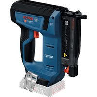
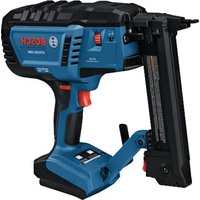
- GSK 64-34 Professional
- WARNING
- Work area safety
- Pneumatic tool safety
- Personal safety
- Pneumatic tool use and care
- Service
- SafetyWarnings for Compressed-air Nailers/Staplers
- Wear safety goggles.
- Product Description and Specifications
- Intended Use
- Product Features
- Technical Data
- Noise/Vibration Information
- Wear hearing protection!
- Declaration of Conformity C
- Connecting the Air Supply (see figure A)
- Connecting the Air Supply to the Pneumatic Tool
- Loading the Magazine (see figures B1-B4)
- | English
- Operation
- Actuation systems
- - Single actuation with safety run
- - Contact actuation
- Starting Operation
- Working with Single Actuation (see figure C)
- Working with Contact Actuation (see figure D)
- Working Advice
- Emptying the Magazine (see figures E1 - E2)
- Adjusting the Depth Stop (see figure F)
- Nails are not driven in deep enough:
- Removing the Discharge Lock-off
- Clearing Jams (see figures G1-G3)
- Changing the Workpiece Protector (see figure H)
- Adjustable Air-outlet cap (see figure 1)
- Transport and Storage
- Maintenance and Service
- Maintenance and Cleaning
- Lubricating the Pneumatic Tool (see figure J)
- | English
- Maintenance Schedule
- Correction of Malfunctions
- Accessories
- After-sales Service and Customer Assistance
- www.bosch-pt.com
- Great Britain
- | Français
- Ireland
- Australia, New Zealand and Pacific Islands
- Republic of South Africa
- Customer service
- Gauteng - BSC Service Centre
- KZN - BSC Service Centre
- Western Cape - BSC Service Centre
- Bosch Headquarters
- Disposal
- Français
- Montagem
- Bortskaffelse
- Avfallshantering
- Ta kaipata dev mnyovrae npakoc baet
- ApaieoTnC aopaleiac anoeaeuoc
- Apaipoeon opnvouevovkappov (Blenc eokocG1-G3)
- Tasfiye
- Osszeszerelés
- Be30tachOCTb THeBMaTHuecknx HnCTpyMeHToB
- Be3oTachOCTbAIODeE
- TuaTeAhoe 06xoxKeHHe CTHeBMOHCTpyMeHTAMN Hx TpaBbHOe TPmMeHHe
- CepBnC
- Yka3aHnI IO TEXHnke 6e3oTachOCTN DAITHEBMaTHuecknx CkO6o- N TB03e3a6NBbIXHHCTpymEHTOB
- OncaHne npoAkyTa n ycAyr
- TpHMeHeHHe ITO Ha3HaueHmIO
- 1306paXeHHbIe coCTaBHbIe qactH
- AaHHbIe IIO WMy H Bn6paunH
- OdeBaIte HayuHKn!
- | Pycckn
- PpHcoeAHHeHnIHTaHHCKaTbIM BO3dYXOM KTHBEMOHcHcTpmyEHTy
- Pa60Ta c HnCtpymeHToM
- CnCTemblcnycka
- BkaioyeHne
- OTKIAOaHTe IODauy CxAToRo BO3aXyA Do HauAHa NaHCTPOIK HNCTPymEtA, CMeHbI OCHaCTKN HAn TpeXeJa
- Pa60Ta C oDnHopa3OBbIM CTYcKOM (Cm. pHc. C)
- Pa60a c KOHTAKTHbIM CTYCKOM (cM.pH.C.D)
- Yka3aHHI IO TpIMHeHIO
- Pycckn
- OtoPokxHeHMe mara3nHa (cm.pnc.E1-E2)
- HactpoKa orpaHHnHTeRAIy6HbI(cM.pnc.F)
- TBO3n 3a6nBAoTcH He AOCTaTOHO Fy60ko:
- Aemontax npedeoxpaHnTea cnTyckOBTO KpOuKa
- YdaAeHHe 3aCtPbBUnx rBo3aEi (cm.pnG1-G3)
- 3aMeHa pe3HHOBOro KOAnauKa (cm.pnc.H)
- PerynpyemarphiopcynkAaBbItyckaBo3Ayxa(cm.pmc.1)
- TpaHcTnOpTHPOBkA H xpaHeHne
- Texo6cayxmbaHne n cepBnC
- TexobcayxHBHne nOuHCTka
- TopyaTe BbIIOAHEHNE Texo6cAYKBAHHN H peMOHTa TOAbKO
- Cma3Ka THeBMOHcTpymeHTa (cm.phc.J)
- IIaan IOAdepKKN B6e3yIpeHOM TexHHueCKOM COCTOHN
- Onnc npoAkyr i nocayr
- Ппзнauthеня
- 3o6paXeHi KOMTOHeHTH
- TIIaKIOeHHIOBtPn DO THeBMaTHuHO TpMaAaDy
- Eknyataia
- ChTeMH Tnycky
- - ODHopa3OBH Nyck 3 NaY3O10
- -KoHTaKTHmTnyck
- Touatokpo60TH
- P60Ta i3 ODHopazOBHM TycKOM (AHB.MaA.C)
- Po60a i3 KOHTAKTHM TYCKOM (AMB.MaA.D)
- YkpaiHcbKa
- Bka3iBKn 10do po6oTH
- TepeaTMMHKHACTPOOBATHPnAA,MIHTNTPnAAaA a6o BiKAactNHtEBMaTHuHHnPPHaA,BHMKHITb
- CtoPoxKHeHH MaRa3HnA (MnB.MaI.E1-E2)
- 3aMiHa rymoBOrO KOBnauKa (AIB, MaI, H)
- 一 Texo6cayroBbAHH Ta peMOHT pHaAaD 03BOAeTbcB
- IIaIITpHMKnB6e3OraHHomyTexHiOMyCTaHI
- TpaHcTnOpTyBaHHaTa 36epirAHHH
- BHaAaIte MaTnHa i OuNCHi 3acO6H ekOaOriuH OuCTHM CTocO6OM.
- 3BaKaIte Ha 3aKoHOaBcI PtHnHcN.
- Eliminare
- Be30nachOCHHa pa6oTHOTOMARCTO
- 6e30nacha pa6ota c IHeBMaTHH HcTpyMeHT
- Be3oNaChocHT hxaopa
- |Блогарскн
- PmKANBO OTHOWeHHe KbM HIOA3BaHe Ha THeBMaTHHHHCTpyMeHTN
- CepBn3
- Yka3aHHa 3a6e3oTachpa60Ta CTHEBMaTHH MaHHH 3a3a6HbHe
- OtticaHne Ha pOdykTa H Bb3MOxHOCHTe My
- MOnTnpaHe
- BkUOBAHe KbMCnCTeMaTa 3a CTBCTEH Bb3Ayx (BHXTe pHr. A)
- BkIOuBaHe Ha ChcTeMaTa 3a CfbCTeH Bb3dYX KbM TTHEBMaTHHH HhCTpyMeHT
- 3apeKdahe Ha Mara3Hna (BHXTe fHyprn B1-B4)
- IpeHdAaPpOMeHrTe HAcTpoKn,da3aMeHrTe IPhCTOCo6aEHN HAn Da ocTaBATE THEBMATuHHN
- Pa6ota
- CnCTeMH Ha3CTpeAbaHe
- BkAIOUBaHe
- Pa6oTa c eHHHm H3ctpeAa (BHXTe pHr.C)
- Pa6ota c KOHTAKTHO H3CTpeAbaHe (BMXTeΦHr.D)
- Yka3aHHa 3pa60ta
- H3npa3BaHe Ha Mara3HHa (BHXTe pHyprn E1-E2)
- HactpoBaHe Ha dbA6OuHHnOrpaHmHTeA(BHXTeΦhrypaF)
- IopdbpxaHe n cepBn3
- TIOAdbpXaHe HIOuHCTBaHe
- Cma3baHe HnHEBMaTHMnHnCTpyMeHT (BHXTeΦnJ)
- TIIaH 3a TexHnuecko 06cayxkBaHe
- Gaisa padeve (attels A)
- aai
- 1
- (Cjallj)j
- (Djgall j)
- (B1-B4jallj)jdllo
- J
- 3x+1 2x+1
- C∈
- bglal 1gbl jy
- #
- b jai 1jai jai jai jai jai
- A
- JgLgLo g
- 0e:2023
- 15j
- L
- (A ygai a gjg j) 1g a jy g a Jlai ogai
- (B1-B4gLdA g
- j≤Locgol<
- ol:woj0oLaiw12Jg0
- gai glaal
- gLglaJgJgagc
Brand : BOSCH
Model : GSK 6434 Professional
Category : Stapler