EcoMatic - Garage door Hormann - Free user manual and instructions
Find the device manual for free EcoMatic Hormann in PDF.
Frequently Asked Questions - EcoMatic Hormann
User questions about EcoMatic Hormann
0 question about this device. Answer the ones you know or ask your own.
Ask a new question about this device
Download the instructions for your Garage door in PDF format for free! Find your manual EcoMatic - Hormann and take your electronic device back in hand. On this page are published all the documents necessary for the use of your device. EcoMatic by Hormann.
USER MANUAL EcoMatic Hormann
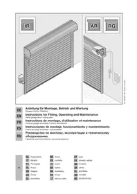
Installation, Operating and Maintenance Instructions
Garage Door Operator
natural_image
Exploded view diagram of mechanical components including a long rod, bracket, and control panel (no text or labels)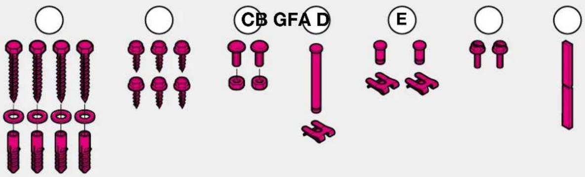
text_image
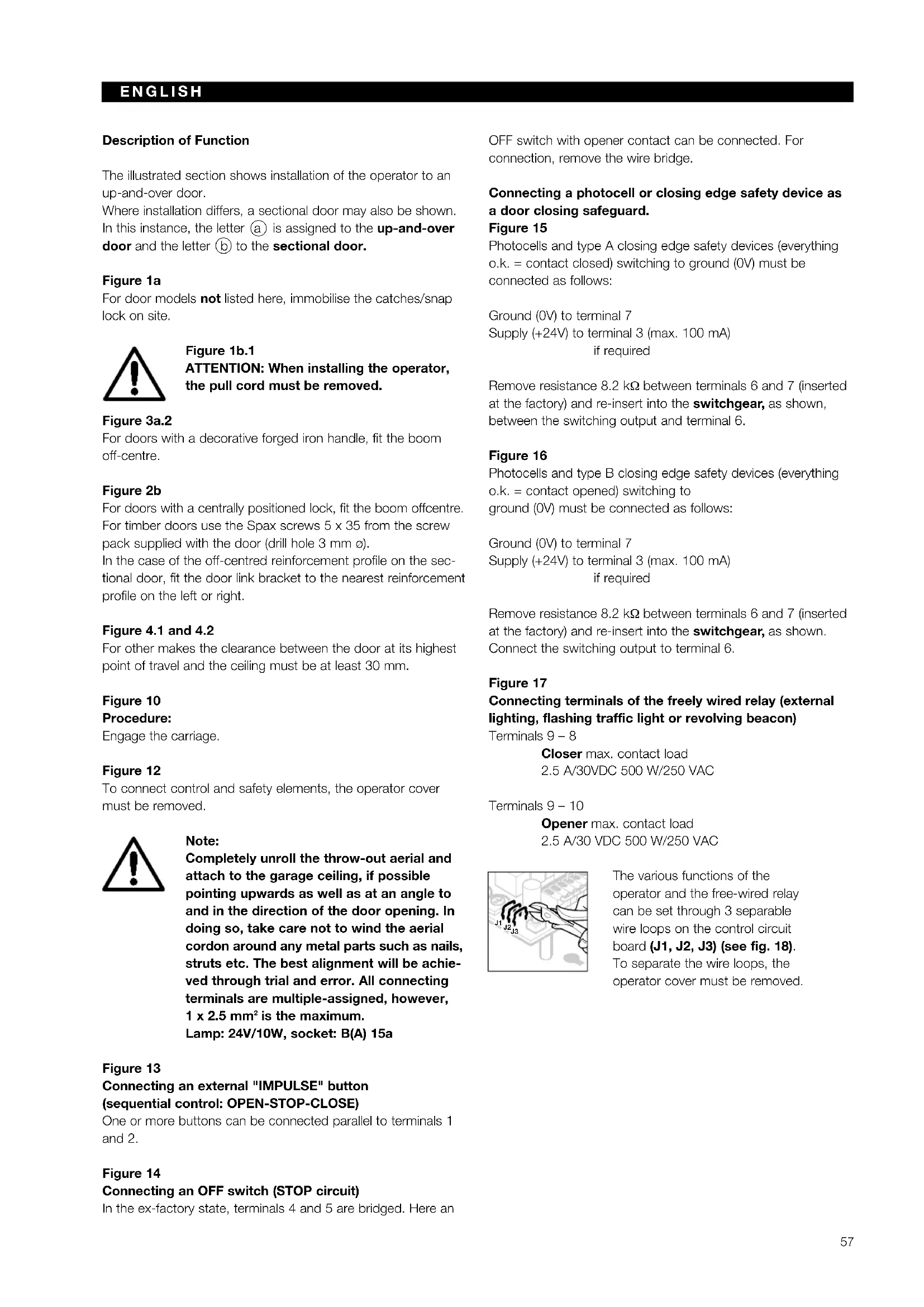
CB GFA D E
Herstellererklärung
Manufacturer declaration
In accordance with the EC Machine Directive 98/37/EEC we hereby declare that in its construction and design as well as in the version marketed by us, the product described below complies with the relevant basic safety and health requirements of the EC Directive. In the event that the product is altered or modified without our approval, this declaration shall lose its validity.
Door operators are components for attaching to garage doors and as such become machines in accordance with the EC Machine Directive 98/37/EEC.
Putting the operator into service is not permitted until conformity of the final product with this Directive has been established.
Product Description
Electric garage door operator
Manufacturer
Ecostar, Upheider Weg 94-98, D-33803 Steinhagen
Tested in accordance
with guideline 98/37/EC
ZH 1/494 04/1989 Routine for power-operated windows and doors
EN 12453 02/2001 Operational safety of poweroperated doors,
requirement and classification
EN 12445 02/2001 Operational safety of power-operated doors, testing methods
EN 12604 03/2000 Doors, mechanical aspects, requirements
EN 12605 08/2000 Doors, mechanical aspects, testing methods
Guideline 73/23/EEC
VDE 0700 Part 238 10/1983 Safety of electrical appliances for domestic use and similar purposes, T238 Drives for windows, doors and similar systems
Axel Becker, executive director

Directives 73/23/EWG
VDE 0700
- Important Information 6
- Illustrated part 38
- Installation 53
- Warranty Terms 103
FRANÇAIS
- Avis important 8
- Illustrations 38
- Montage
- Conditions de garantie 103
NEDERLANDS
text_image
Warning sign with car, soccer ball, and warning triangle warning
text_image
Safety warning illustration showing a child sitting outside a window with a bear, warning symbol indicating danger, and warning sign.We are delighted that you have decided to purchase one of our products. Please keep these instructions safe for later reference.
Please observe the following instructions. They provide you with important information on the safe installation and operation of your garage door operator, ensuring that this product will give you pleasure for many years to come.
In the interests of human safety it is vital that the instructions contained in this instruction manual be followed in full.
Important Safety Instructions
This garage door operator is designed for the automatic operation of spring-balanced up-and-over doors and sectional doors in the non-commercial sector. Use in the commercial sector is not permitted. In the event that the customer carries out his own structural changes or undertakes improper installation work or arranges for same to be carried out/undertaken, without our prior approval and contrary to the manufacturer's given guidelines, then we shall be exempt from our guarantee obligations and product liability.
Any further processing must ensure that the national regulations governing the operation of electrical equipment are complied with. Moreover, we shall accept no responsibility for the inadvertent or negligent operation or improper maintenance of the door, the accessories and the weight counterbalance of the door.
Batteries and light bulbs are not covered by the guarantee. The design of the operator is not suitable nor intended for the opening and closing of heavy doors, i.e. doors that can no longer be opened or closed manually or where this is only possible with great difficulty. Before installing the operator it is therefore necessary to check the door and make sure that it can still be easily moved by hand.
To carry out this check, raise the door approx. 1 metre and then let it go. The door should keep this position, moving neither up nor down. If the door should move in any of the two directions, there is a risk that the compensating springs are incorrectly adjusted or defective. In this case increased wear and malfunctioning of the door system can be expected.
Caution: Mortal danger!
Do not attempt to change, re-adjust, repair or move the compensating springs for the door's counterbalance mechanism or their holders. The springs are under great tension and can cause serious injury. For your own safety, only allow work on the door's compensating springs to be carried out by your garage door's service engineers.
In addition, check the entire door system – joints/hinge points, door bearings, cables, springs and fastenings – for wear, possible damage and a faulty counterbalance mechanism. Check for signs of rust, corrosion or fractures. The door system may not be used if repair or adjustment work needs to be carried out.
Always remember that a fault in the door system or a wrongly aligned door can cause injury.
Before installing the operator, have any necessary maintenance and repair work carried out by your garage door's service engineers.
The function of the mechanical release must be checked once a month. The cord knob may only be actuated when the door is closed, otherwise in the case of weak, broken or defective springs or a faulty counterbalance mechanism there is a risk that the door could quickly slam shut of its own accord.

Important Instructions for Safe Installation
ATTENTION: Incorrect installation can result in serious injuries. Always cover over the operator before carrying out any drilling. Please follow all the installation instructions.
Before the operator is installed, any of the door's mechanical locks and latches not needed for power operation of the garage door, should be immobilised. This includes in particular any locking mechanisms connected with the door lock.
Before installing the garage door operator, check that the door is in a good mechanical condition, is correctly balanced and
text_image
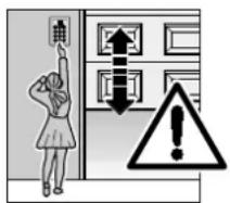
Safety warning illustration showing a person using a control panel with an upward arrow and warning symbolopens and closes in the proper manner. Permanently installed controls (such as buttons or similar devices) should be installed within sight of the door but well away from any moving parts and at a height of at least 1.5 metres. It is vital that they are installed out of the reach of children!
Caution notices warning about the trap risk must be permanently fixed in a conspicuous place in the proximity of the permanently installed buttons used to actuate the operator.
The garage ceiling must be constructed in such a way so as to guarantee safe, secure anchoring of the operator. In the case of ceilings which are too high or too light-weight, the operator must be attached to additional braces.
The operator is designed for use in dry buildings and therefore may not be installed outdoors. The door height must not exceed a maximum of 3 metres. The clearance between the highest point of the door and the ceiling (also during the up-and-over action of the door) must be at least 30 mm. Please check the dimensions!
If there is inadequate clearance, the operator may also be installed behind the opened door, provided sufficient space is available. In such instances, an extended door link must be used.
The door operator can be positioned off-centre by a maximum of 500 mm, the exception being sectional doors with high-lift tracks (track application "H") where a special track fitting is required. The required shockproof electric socket should be installed next to the operator head at a distance of approx. 50 cm.
ENGLISH

ATTENTION: Electrical installation on site must comply with the relevant safety regulations (230/240 V AC, 50/60 Hz). Electrical connections may only be carried out by a qualified electrician! External voltage at connecting terminals 1-7 of the controls will completely destroy the electronics.
In carrying out the installation work, the applicable regulations regarding working safety must be complied with. Make sure that the cable of the operator's mechanical release cannot get caught up in the ceiling's support system or in any other protruding parts of vehicles or the door.
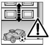
Make sure that no persons or objects are located within the door's range of travel.
text_image
Warning sign with car, soccer ball, and warning triangle indicating accident or hazard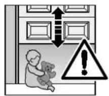
text_image
Safety warning illustration showing a child holding a teddy bear next to a door with arrows and a warning symbol.Initial function checks as well as programming or extending the remote control should always be carried out from inside the garage.

ATTENTION: For garages without a second entrance, an emergency release must be fitted to prevent persons from getting locked in. This must be ordered separately and its function checked once a month.
Instructions for Using the Operator

ATTENTION: Do not allow anyone to hang bodily from the pull cord with knob
Before carrying out any work on the operator, disconnect the mains plug. Instruct all persons using the door system how to
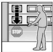
operate it properly and safely. Demonstrate and test the safety return and the mechanical release. Only ever operate the door provided the door's range of travel is located within your field of vision.
text_image
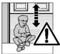
Safety warning illustration showing a child sitting on the floor with an upward arrow and warning symbolATTENTION: Keep hand transmitters out of the reach of children.
Wait until the door has come to a complete halt before entering the door's range of travel. Before driving in or out of the garage, make sure that the door has opened fully.
Tensioning the Drive Belt
The operator's toothed belt has been optimally pretensioned at the factory. During the starting and braking phases of large doors it can happen that the drive belt hangs out of the profiled boom for a brief while. This, however, is of no technical disadvantage nor does it have a negative effect on the operator's function and service life.

ATTENTION: Do not reach into the boom with the fingers → trap risk!
Maintenance Advice
The garage door operator is maintenance-free. For your own safety, however, we recommend that you have the door system checked once a year by a specialist.
Airborne noise emission of the garage door operator: at a distance of 3 m the equivalent continuous sound pressure level of 70 dB(A-weighted) is not exceeded.

See text section!
Copyright.
No reproduction even in part is allowed without our permission.
All details subject to change.
Cher client,
text_image
Safety warning illustration showing a person pointing at a door with an upward arrow and warning symboltext_image
Safety warning illustration showing car, soccer ball, and warning triangle with arrows indicating directions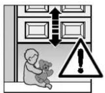
text_image
Safety warning illustration showing a child teddy bear inside a room with upward arrows and a triangular warning symbol.text_image
Safety warning illustration showing a child sitting inside a room with upward and downward arrows, a warning symbol, and an exclamation mark.text_image
Safety warning illustration showing a person pressing a control panel with an upward arrow and warning symboltext_image
Warning sign with car, soccer ball, and warning triangle indicating accident or hazard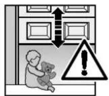
text_image
Safety warning illustration showing a teddy bear inside a room with double-headed arrows and a warning symbol.text_image
Safety warning illustration showing a child sitting on the floor with an upward arrow and warning symboltext_image
Safety warning illustration showing a person pointing at a door with a warning symbol indicating hazard.text_image
Warning sign with car, warning triangle, and double-headed arrows indicating bidirectional or perpendicular actions
text_image
Safety warning illustration showing a child teddy bear inside a room with upward arrows and a warning symbol.text_image
Safety warning illustration showing a person pressing a door with an upward arrow and a warning symbol.text_image
Safety warning sign showing car collision with soccer ball and warning triangle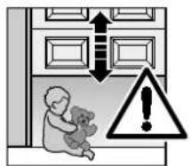
text_image
Safety warning illustration showing a child holding a teddy bear next to a door with upward arrows and a warning symbol.text_image
Safety warning illustration showing a child sitting inside a room with upward and downward arrows, a warning symbol, and an exclamation mark.text_image
Safety warning illustration showing a person pointing at a control panel with an upward arrow and warning symboltext_image
Safety warning illustration showing vehicle collision with warning triangle and building layout
text_image
Safety warning illustration showing a child holding a teddy bear next to a door with arrows and a warning symbol.text_image
Safety warning illustration showing a child sitting with a downward arrow and warning symboltext_image
Safety warning illustration showing car, soccer ball, and warning triangle with arrows and exclamation mark
text_image
Safety warning illustration showing a child holding a teddy bear next to a door with arrows and a warning symbol.text_image
Safety warning illustration showing a child sitting inside a room with upward and downward arrows, a warning symbol, and an exclamation mark.text_image
Safety warning illustration showing a person pressing a door with a double-headed arrow and a warning symbol.text_image
Safety warning illustration showing car accident with vehicle, soccer ball, and warning triangle
text_image
Safety warning illustration showing a child holding a teddy bear next to a door with double-headed arrows and a warning symbol.text_image
Safety warning illustration showing a child sitting outside a doorway with an upward arrow and warning symboltext_image
Safety warning illustration showing a person pressing a doorbell with a warning symbol indicating hazard.text_image
Safety warning illustration showing a car, soccer ball, and warning symbols with an exclamation mark
text_image
Safety warning illustration showing a child holding a teddy bear next to doors with arrows and a warning symboltext_image
Safety warning illustration showing a child sitting on the floor with an upward arrow and warning symboltext_image
Safety warning illustration showing a person pressing a control panel with an upward arrow and a warning symbol.text_image
Safety warning illustration showing car accident with warning triangle and vehicle symbol
text_image
Safety warning illustration showing a baby teddy bear inside a door with warning symbols and an exclamation mark.text_image
Safety warning illustration showing a child sitting inside a room with an upward arrow and warning symboltext_image
Warning sign with car, soccer ball, and warning triangle indicating absence of a vehicle or accident
text_image
Safety warning illustration showing a child holding a teddy bear, with arrows indicating upward and downward directions, and a warning symbol.text_image
Safety warning illustration showing a child sitting inside a room with an upward arrow and warning symboltext_image
Safety warning illustration showing a person using a control panel with warning symbolstext_image
Safety warning sign with car, soccer ball, and warning triangle warning symbol
text_image
Safety warning illustration showing a child holding a teddy bear and a warning symbol with an exclamation mark.text_image
Safety warning illustration showing a person pressing a control panel with an upward arrow and warning symboltext_image
Safety warning illustration showing car, soccer ball, and warning symbol with arrows and exclamation mark
text_image
Safety warning illustration showing a child teddy bear outside a door with downward arrows and a warning symbol.SUOMI
text_image
Safety warning illustration showing a child sitting with a warning symbol indicating hazard or caution.text_image
Safety warning illustration showing a child holding a teddy bear next to a door with warning symbols and an exclamation mark.text_image
Safety warning illustration showing a person pressing a doorbell with a warning symbol indicating hazard.text_image
Safety warning illustration showing car, soccer ball, and warning triangle with arrows indicating upward movement
text_image
Safety warning illustration showing a child holding a teddy bear next to a door with double-headed arrows and a warning symbol.text_image
Safety warning illustration showing a child sitting in a room with an upward arrow and warning symboltext_image
Safety warning illustration showing car, soccer ball, and warning triangle with arrows indicating directions
text_image
Safety warning illustration showing a child teddy bear inside a room with upward arrows and a warning symbol.text_image
Safety warning illustration showing a child sitting on the floor with an upward arrow and warning symboltext_image
1a 1a.1 1a.2 1a.3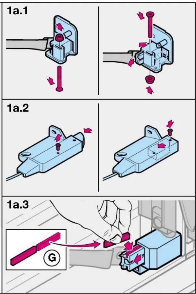
text_image
1a.1 1a.2 1a.3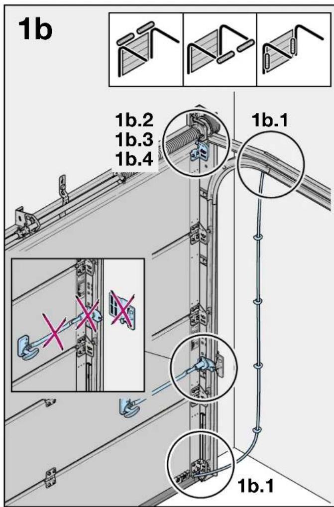
text_image
1b 1b.2 1b.3 1b.4 1b.1 X X 1b.1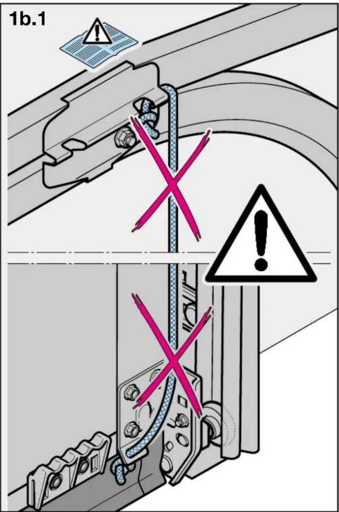
text_image
1b.1 X X
text_image
2a Ø5 B 1/2 1/2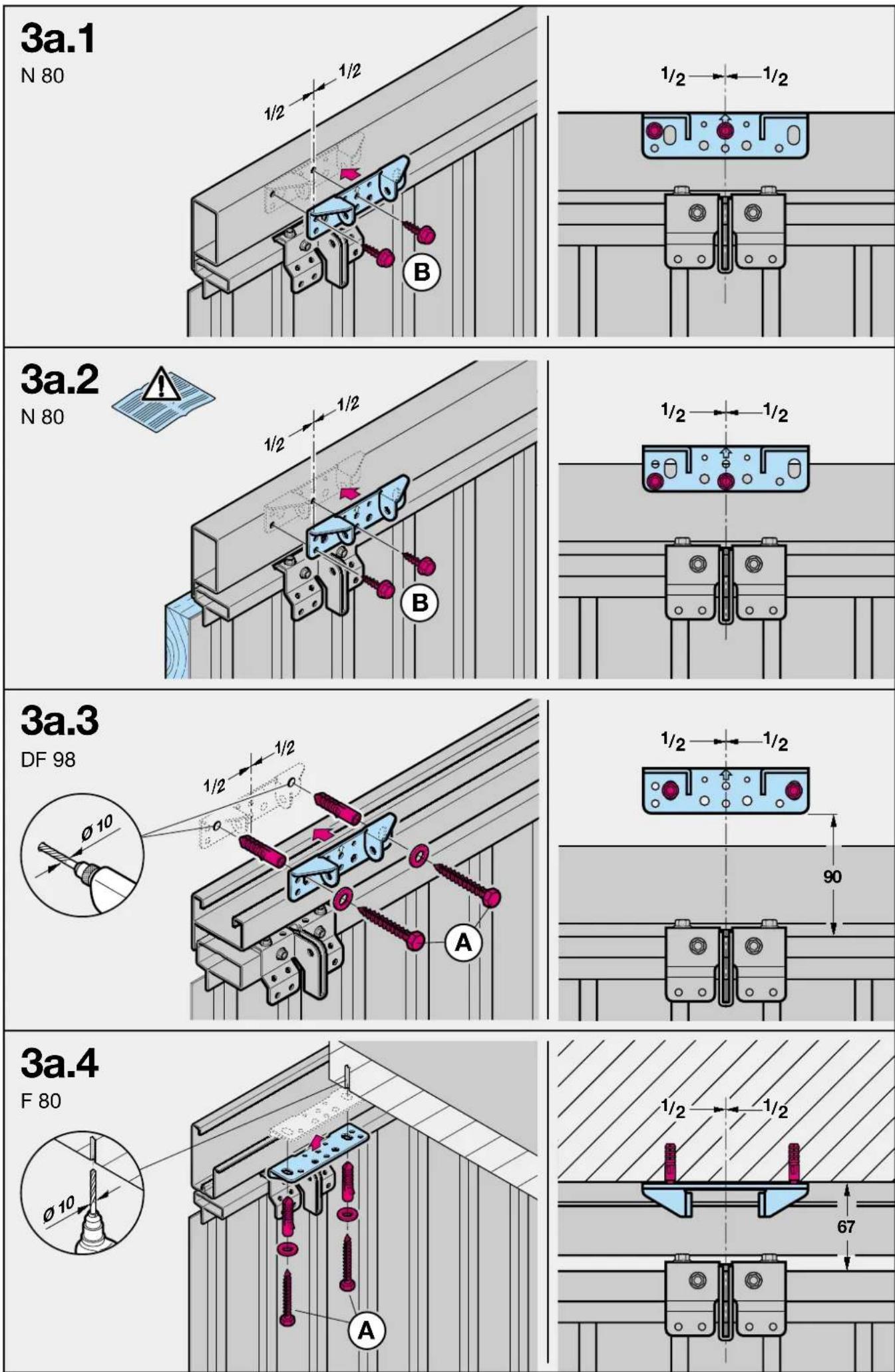

text_image
2b Ø5 B
text_image
3b.1 LTE/LPU/LTH 40 ≥113 A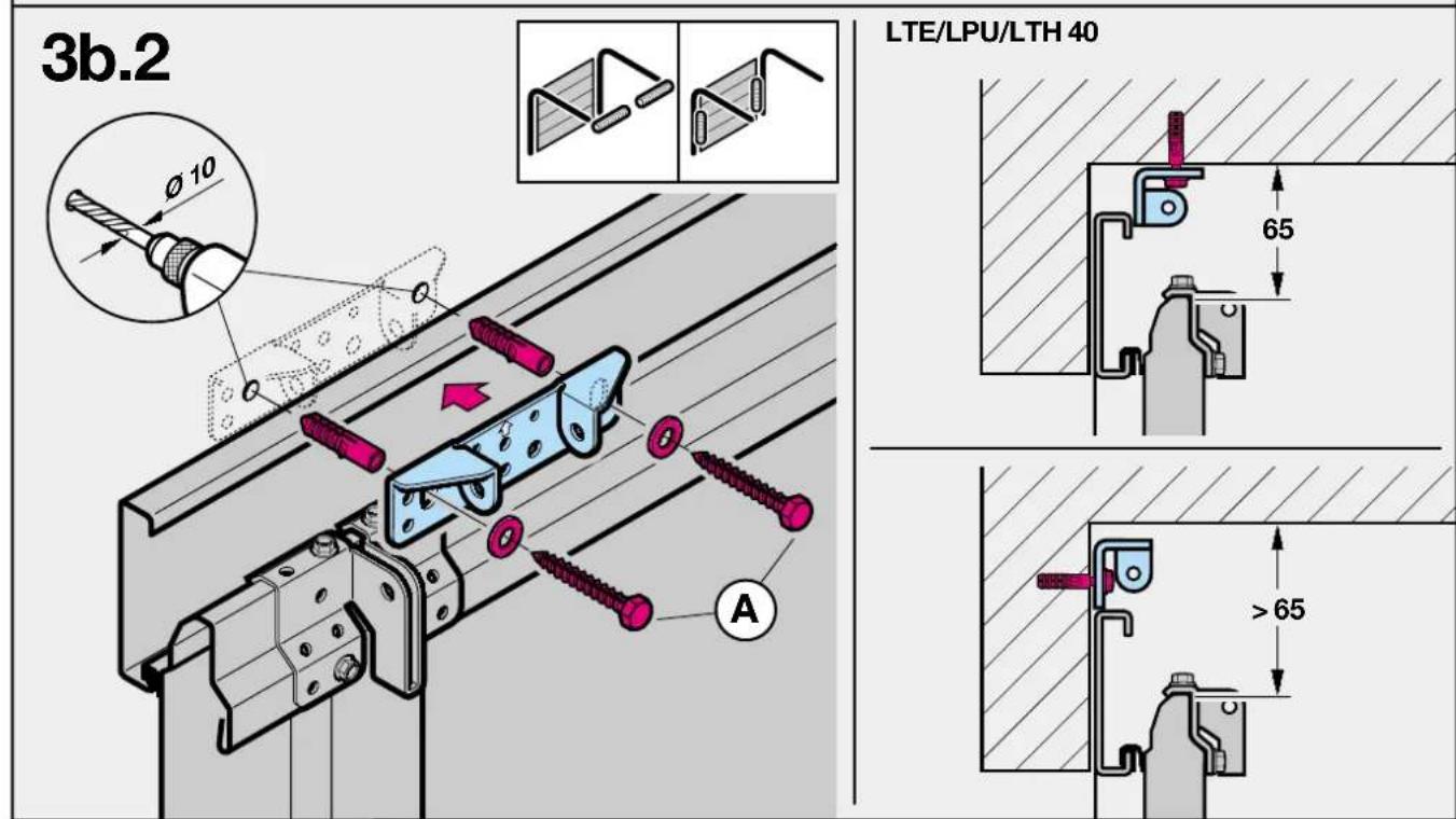
text_image
3b.2 LTE/LPU/LTH 40 65 >65 A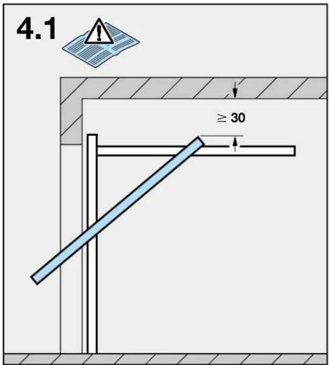
text_image
4.1 ≥ 30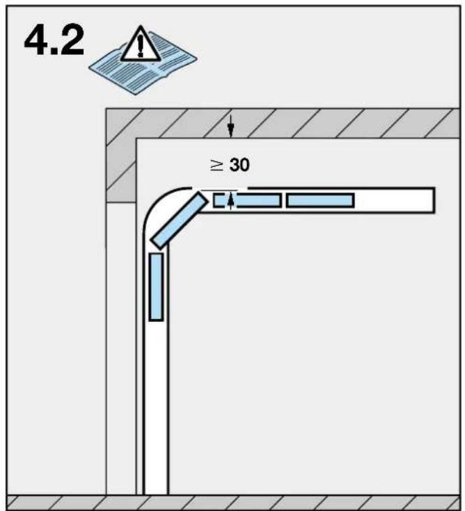
text_image
4.2 ≥ 30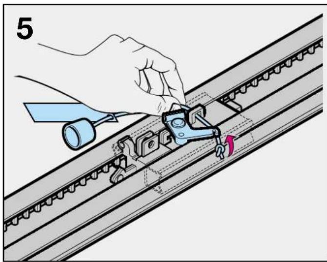
natural_image
Illustration of a hand using a tool to adjust or install a mechanical component on a rail track (no text or symbols visible)
natural_image
Technical diagram of a mechanical assembly with a tool and bracket (no text or symbols)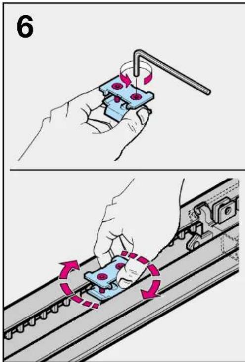
text_image
6
text_image
Technical diagram showing mechanical assembly with labeled components and directional arrows indicating motion or movement.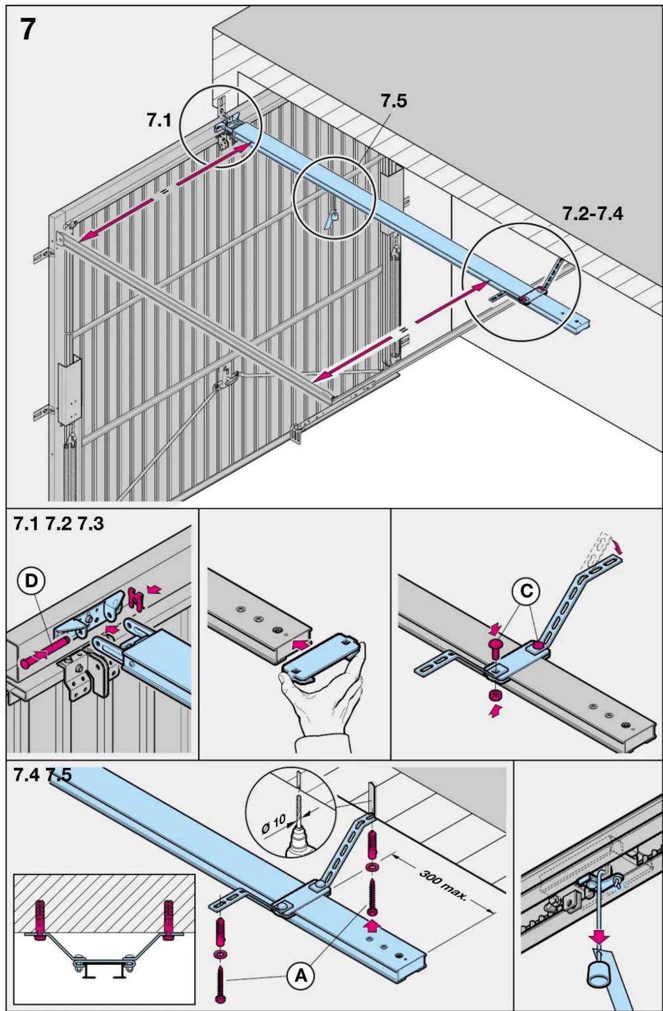
text_image
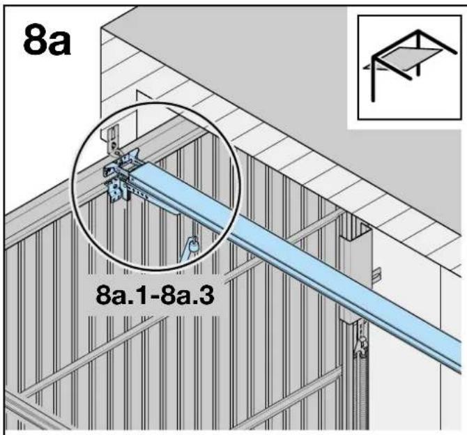
8a 8a.1-8a.3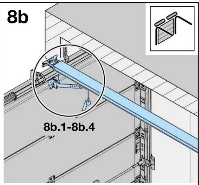
text_image
8b 8b.1-8b.4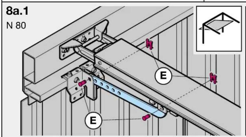
text_image
8a.1 N 80 E E E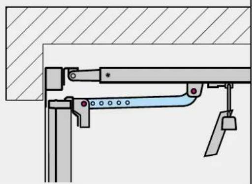
natural_image
Technical diagram of a mechanical assembly with no visible text or symbols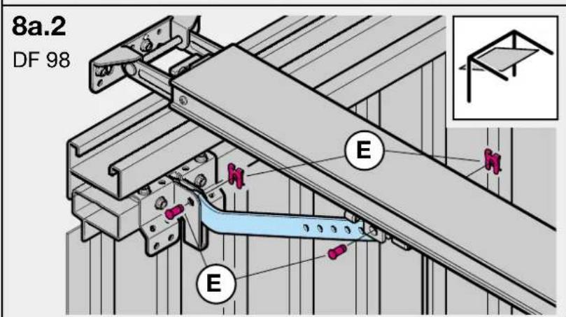
text_image
8a.2 DF 98 E E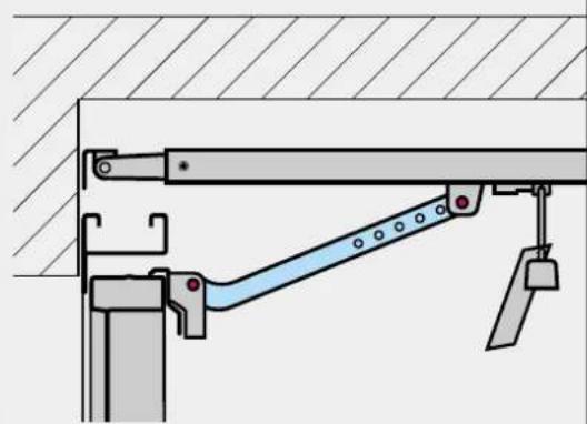
natural_image
Technical diagram of a mechanical lifting or bracket assembly (no text or symbols)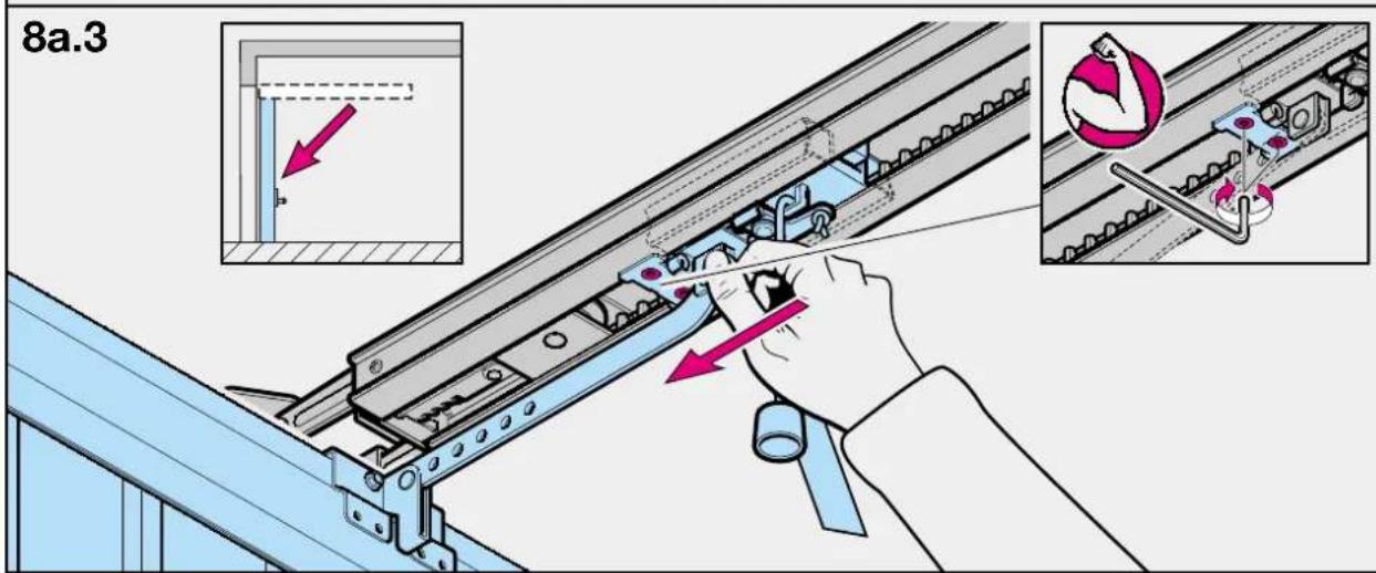
text_image
8a.3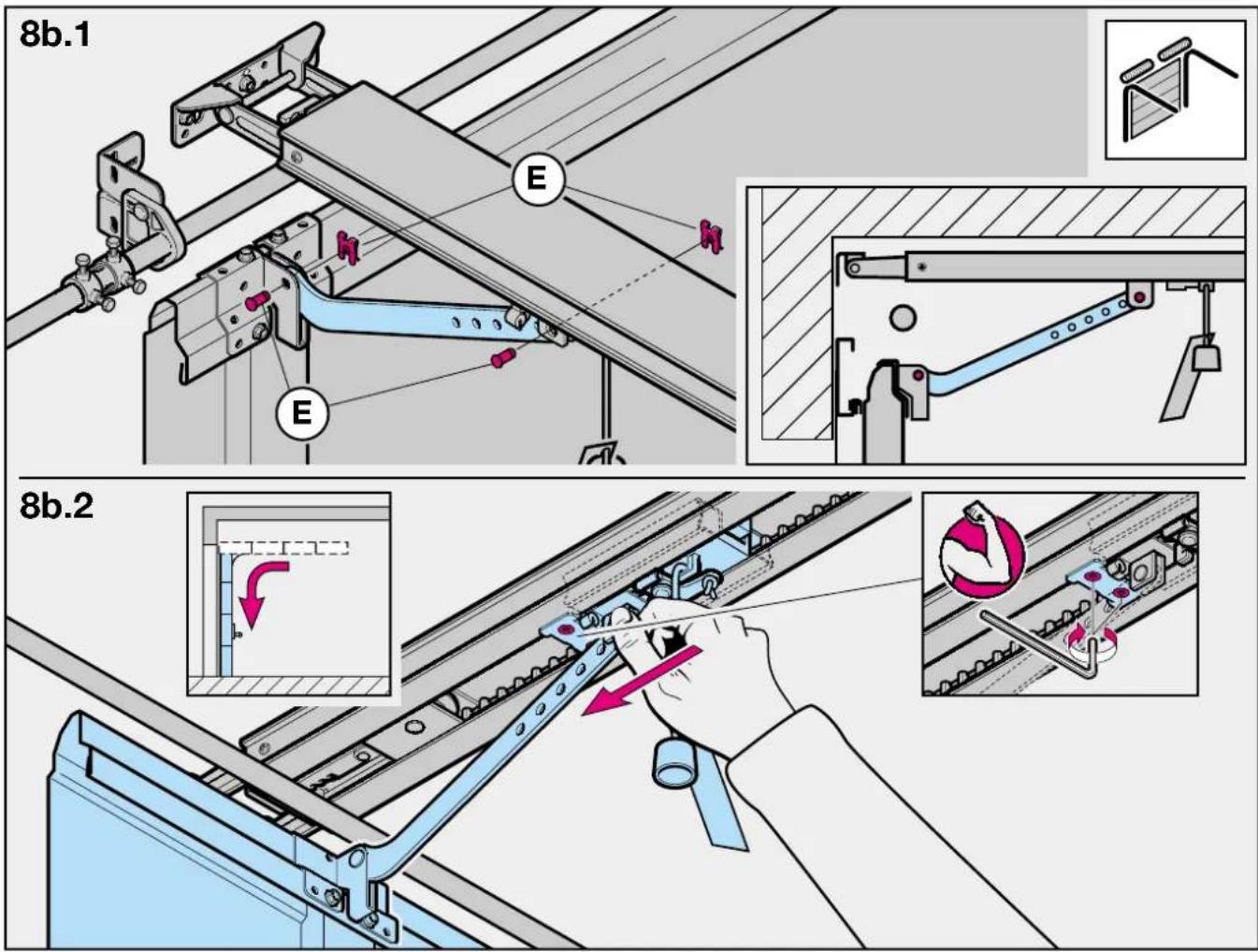
text_image
8b.1 E E 8b.2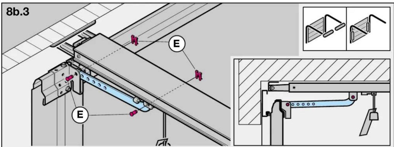
text_image
8b.3 E E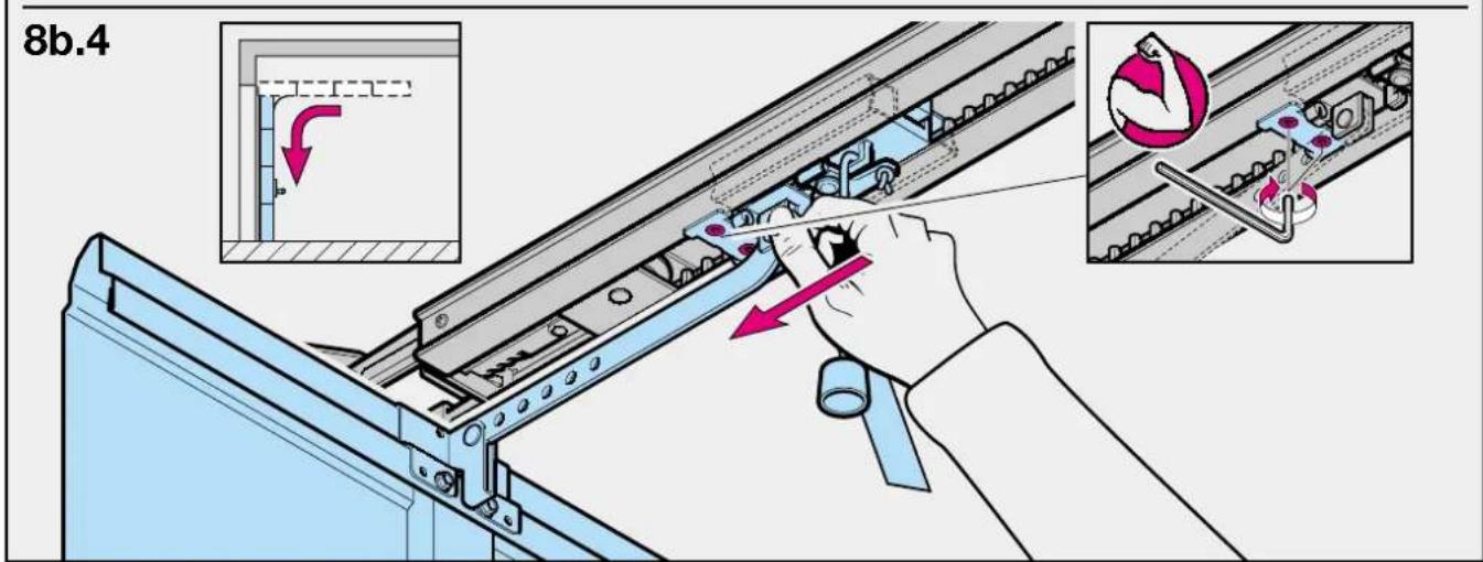
text_image
8b.4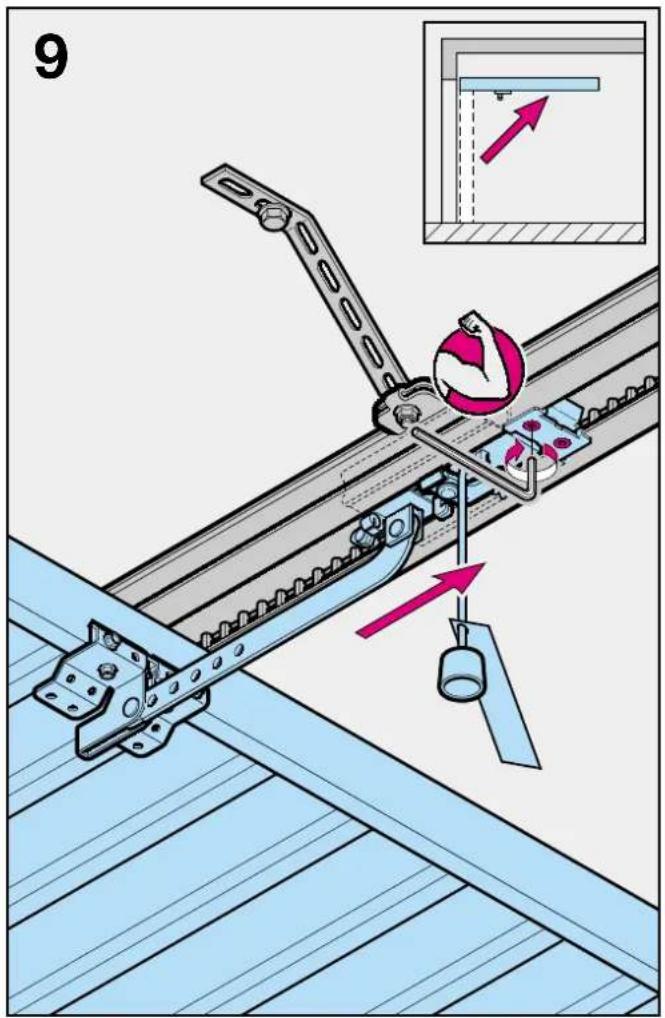
text_image
9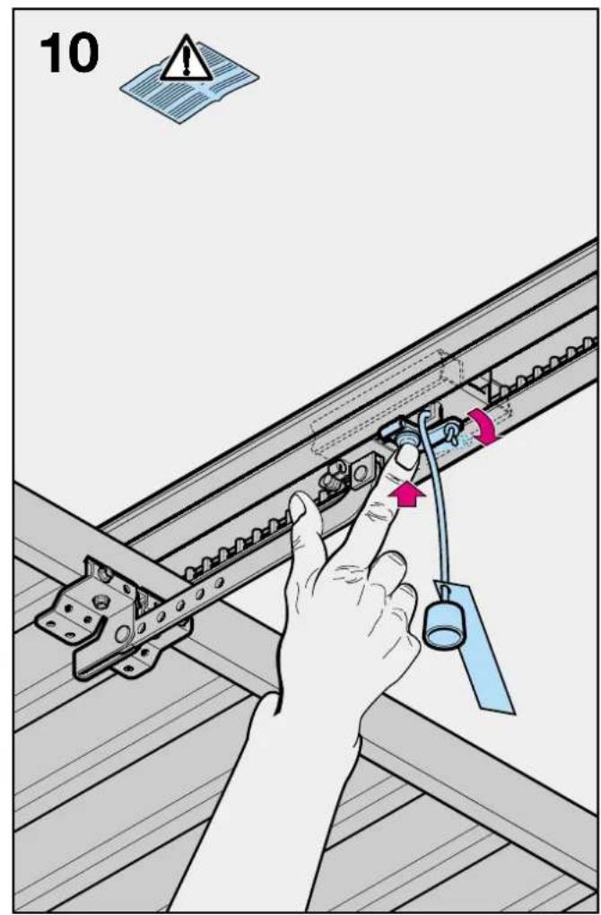
text_image
10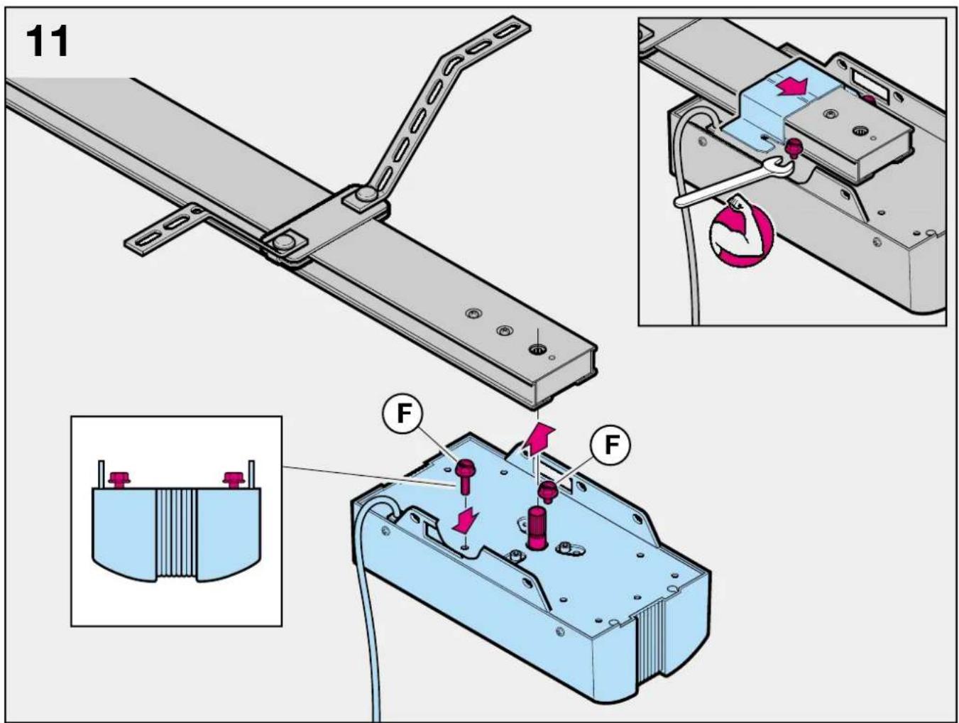
text_image
11 F F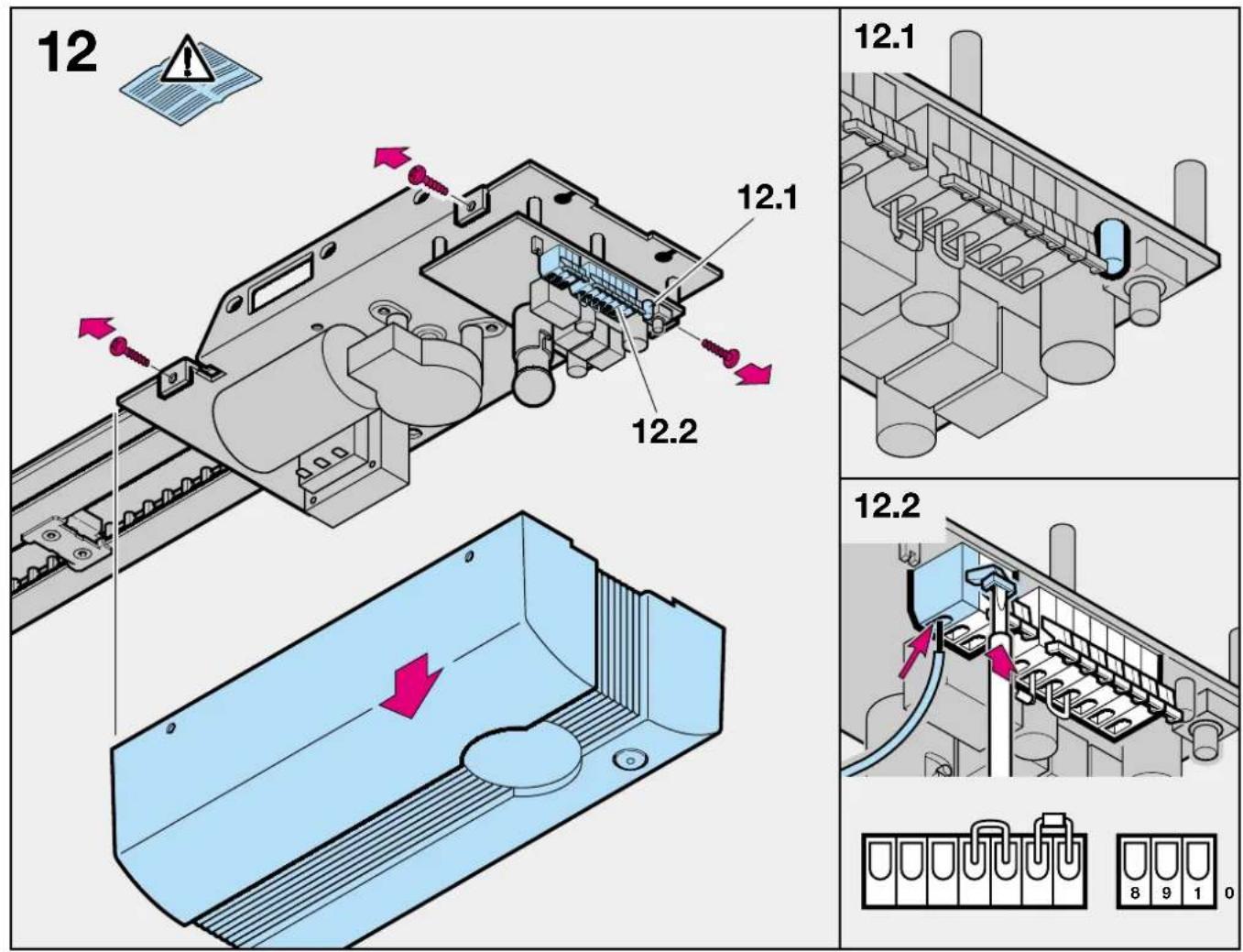
text_image
12 12.1 12.2 12.1 12.2 8 9 1 0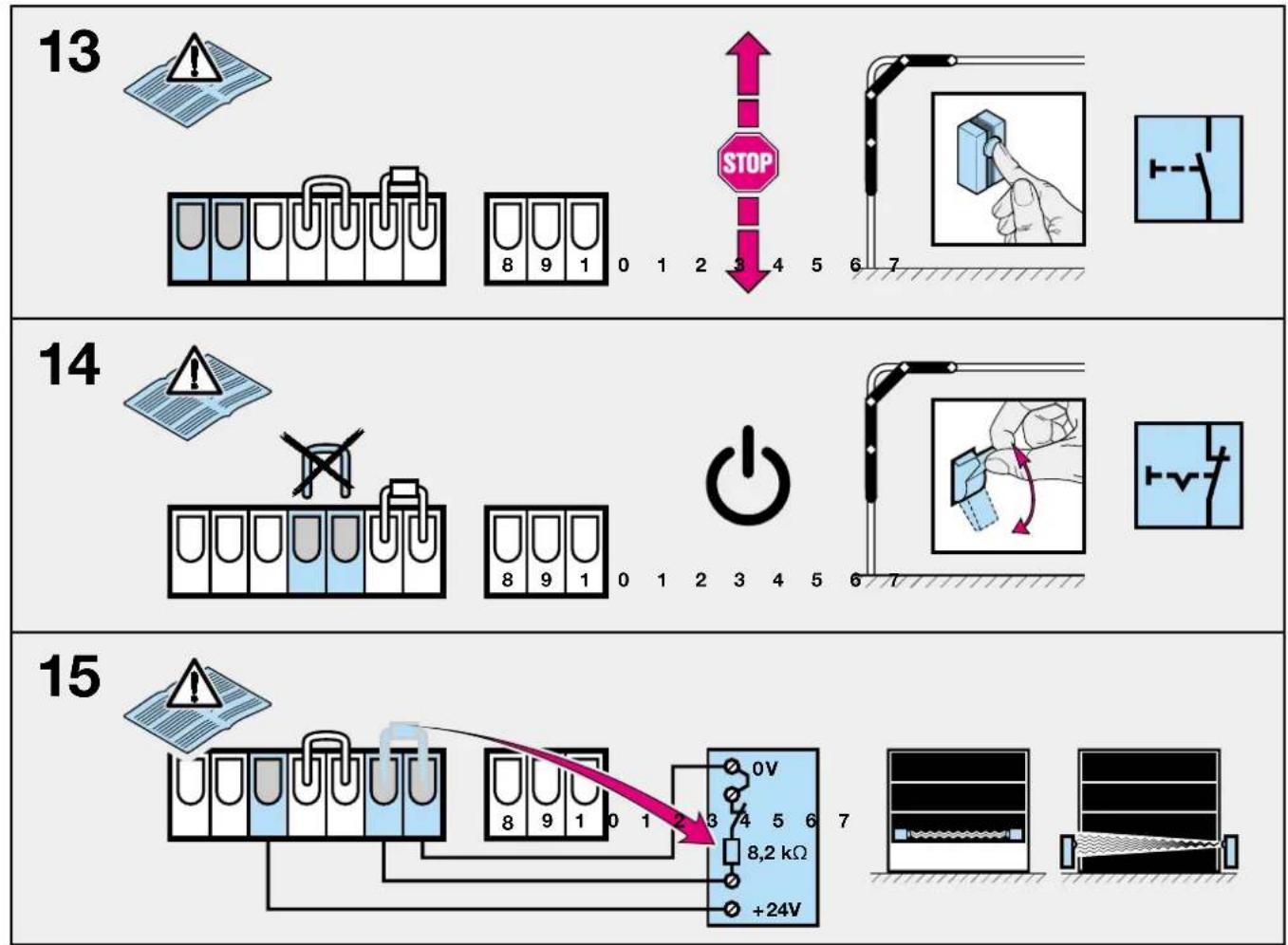
flowchart
graph TD
    A["13: Inverter"] --> B["8: Test tube with warning icon"]
    B --> C["1: Stop"]
    C --> D["STOP"]
    D --> E["8: Switch"]
    E --> F["0: Power Supply"]
    F --> G["2: Switch"]
    G --> H["3: Power Supply"]
    H --> I["4: Switch"]
    I --> J["5: Power Supply"]
    J --> K["6: Switch"]
    K --> L["7: Switch"]

    M["14: Inverter"] --> N["8: Test tube with warning icon"]
    N --> O["1: Power Supply"]
    O --> P["2: Switch"]
    P --> Q["3: Power Supply"]
    Q --> R["4: Switch"]
    R --> S["5: Power Supply"]
    S --> T["6: Switch"]
    T --> U["7: Switch"]

    V["15: Inverter"] --> W["8: Test tube with warning icon"]
    W --> X["1: Power Supply"]
    X --> Y["2: Switch"]
    Y --> Z["3: Power Supply"]
    Z --> AA["4: Switch"]
    AA --> AB["5: Power Supply"]
    AB --> AC["6: Switch"]
    AC --> AD["7: Switch"]

    style A fill:#f9f,stroke:#333
    style M fill:#f9f,stroke:#333
    style V fill:#f9f,stroke:#333
    style W fill:#f9f,stroke:#333
    style X fill:#f9f,stroke:#333
    style Y fill:#f9f,stroke:#333
    style Z fill:#f9f,stroke:#333
    style AA fill:#f9f,stroke:#333
    style AB fill:#f9f,stroke:#333
    style AC fill:#f9f,stroke:#333
    style AD fill:#f9f,stroke:#333
16
text_image
Electrical circuit diagram showing a power supply with test tubes, a 24V power source, and a waveform display panel.17
text_image
Diagram showing a test tube setup with labeled components and a light bulb, including warning symbol and numbered parts.18
text_image
1/N-230/240 V 50/60Hz S 2 X2 X1 M 24V/10W B(A)15s 3 2 1 J1 J2 J3 LED 8 9 1 0 2 3 4 5 6 719
text_image
HE 1 GN WH BN 8 9 1 0 120
text_image
Technical diagram illustrating a mechanical assembly process with labeled components and directional arrows indicating motion or movement.21
text_image
Diagram illustrating a mechanical process with directional arrows and a hand interacting with a circular button.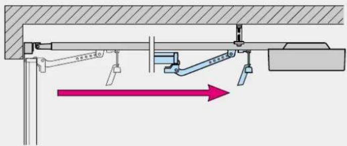
text_image
Technical diagram showing mechanical assembly with labeled components and directional arrow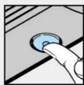
text_image
Technical diagram showing mechanical assembly with labeled components and directional arrows indicating motion or force directions.22.1
text_image
Diagram illustrating electrical switch mechanism with labeled components and directional arrows indicating current flow or polarity.22.2
Description of Function
The illustrated section shows installation of the operator to an up-and-over door.
Where installation differs, a sectional door may also be shown. In this instance, the letter ⓐ is assigned to the up-and-over door and the letter ⓑ to the sectional door.
Figure 1a
For door models not listed here, immobilise the catches/snap lock on site.

Figure 1b.1
ATTENTION: When installing the operator, the pull cord must be removed.
Figure 3a.2
For doors with a decorative forged iron handle, fit the boom off-centre.
Figure 2b
For doors with a centrally positioned lock, fit the boom offcentre. For timber doors use the Spax screws 5 x 35 from the screw pack supplied with the door (drill hole 3 mm ø). In the case of the off-centred reinforcement profile on the sectional door, fit the door link bracket to the nearest reinforcement profile on the left or right.
Figure 4.1 and 4.2
For other makes the clearance between the door at its highest point of travel and the ceiling must be at least 30 mm.
Figure 10
Procedure:
Engage the carriage.
Figure 12
To connect control and safety elements, the operator cover must be removed.

Note:
Completely unroll the throw-out aerial and attach to the garage ceiling, if possible pointing upwards as well as at an angle to and in the direction of the door opening. In doing so, take care not to wind the aerial cordon around any metal parts such as nails, struts etc. The best alignment will be achieved through trial and error. All connecting terminals are multiple-assigned, however, 1 x 2.5 mm ^2 is the maximum. Lamp: 24V/10W, socket: B(A) 15a
Figure 13
Connecting an external "IMPULSE" button
(sequential control: OPEN-STOP-CLOSE)
One or more buttons can be connected parallel to terminals 1 and 2.
Figure 14
Connecting an OFF switch (STOP circuit)
In the ex-factory state, terminals 4 and 5 are bridged. Here an
OFF switch with opener contact can be connected. For connection, remove the wire bridge.
Connecting a photocell or closing edge safety device as a door closing safeguard.
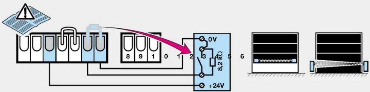
Figure 15
Photocells and type A closing edge safety devices (everything o.k. = contact closed) switching to ground (0V) must be connected as follows:
Ground (0V) to terminal 7
Supply (+24V) to terminal 3 (max. 100 mA)
if required
Remove resistance 8.2 kΩ between terminals 6 and 7 (inserted at the factory) and re-insert into the switchgear, as shown, between the switching output and terminal 6.
Figure 16
Photocells and type B closing edge safety devices (everything o.k. = contact opened) switching to ground (0V) must be connected as follows:
Ground (0V) to terminal 7
Supply (+24V) to terminal 3 (max. 100 mA)
if required
Remove resistance 8.2 kΩ between terminals 6 and 7 (inserted at the factory) and re-insert into the switchgear, as shown. Connect the switching output to terminal 6.
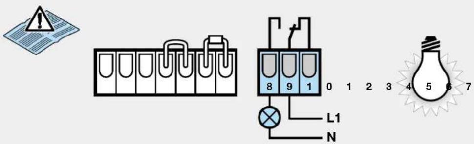
Figure 17
Connecting terminals of the freely wired relay (external lighting, flashing traffic light or revolving beacon)
Terminals 9 - 8
Closer max. contact load
2.5 A/30VDC 500 W/250 VAC
Terminals 9 – 10
Opener max. contact load
2.5 A/30 VDC 500 W/250 VAC
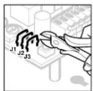
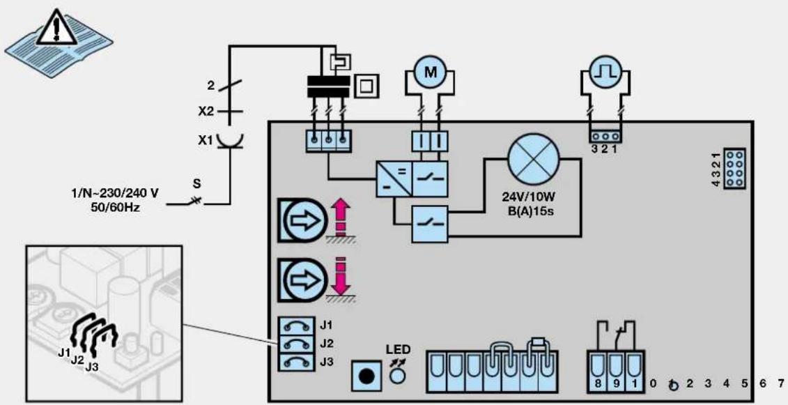
The various functions of the operator and the free-wired relay can be set through 3 separable wire loops on the control circuit board (J1, J2, J3) (see fig. 18). To separate the wire loops, the operator cover must be removed.
| Functions of the operator and the free-wired relay | |
| J1 | Operator without special functions (factory setting) - Relay is activated with the operator lighting, but without flashing |
| J2 | |
| J3 | |
| J1 | Operator without special functions - Relay is activated on reaching the "CLOSE" travel limit (DOOR CLOSED signal) |
| J2 | |
| J3 | |
| J1 | Automatic timed closing from "OPEN" travel limit position after 30 secs. open phase and 2 sec. warning phase - Relay is permanently activated during open and warning phases as well as when the door is in motion |
| J2 | |
| J3 | |
| J1 | Automatic timed closing from the "OPEN" travel limit position after 30 secs. open phase and 2 secs. warning phase - Relay flashes slowly during the open phase and rapidly during the warning phase: continues to flash normally when door is in motion |
| J2 | |
| J3 | |
| J1 | Warning phase (2 secs.) always activated - Relay is permanently activated during the warning phase as well as when the door is in motion |
| J2 | |
| J3 | |
| J1 | Warning phase (2 secs.) always activated - Relay flashes rapidly during the warning phase; continues to flash normally when the door is in motion |
| J2 | |
| J3 | |
| J1 | Warning phase (2 secs.) always activated - Automatic timed return from the "OPEN" travel limit position after 30 sec. open phase and 2 sec. warning phase - Relay is permanently activated during the open and warning phases as well as when the door is in motion |
| J2 | |
| J3 | |
| J1 | Warning phase (2 secs.) always activated - Automatic timed return from the "OPEN" travel limit position after 30 secs. open phase and 2 sec. warning phase - Relay flashes slowly during the open phase and rapidly during the warning phase; continues to flash normally when the door is in motion |
| J2 | |
| J3 |
Open phase:
The time the door waits in the "OPEN" travel limit position. An impulse given during this time restarts the open phase.
Warning phase:
The time between the command to set the door in motion and the onset of door movement. If a new command is given
during this phase, the warning phase ends without subsequent door movement.
Automatic timed return:
Door closes automatically after a preset phase on reaching the "OPEN" travel limit.
For safety reasons we strongly advise using a photocell or closing edge safety device when the automatic timed return is activated.
Figure 18
Wiring diagram
Note: In order to carry out the following steps, the carriage must be engaged (see fig. 10). If the garage does not have a separate entrance, then the further points should be carried out from inside the garage:
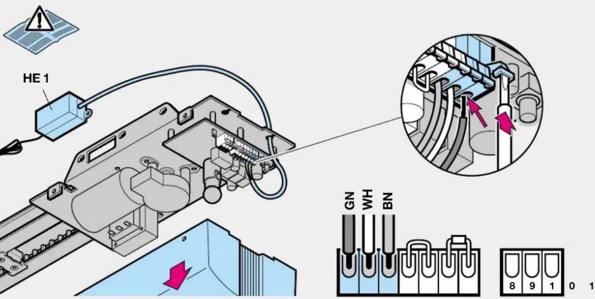
Figure 19
Connecting the remote control
The wiring of the radio receiver is to be connected as follows:
- green wire to terminal 1 (0V)
- white wire to terminal 2 (signal)
- brown wire to terminal 3 (+24V)
Figure 20
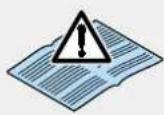
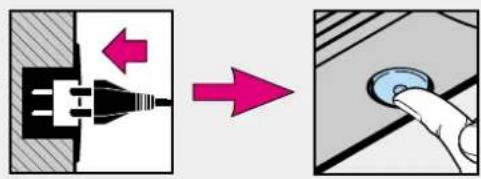
Deleting the door data
- Disconnect from the mains by pulling out the plug
- Circuit board button and keep pressed.
- Then immediately re-insert the mains plug and circuit board button pressed for as long as the operator lighting flashes. If this flashes just once, this indicates that the door data has been deleted. You can then proceed to fig. 21 – putting into operation.
Figure 21
Putting into operation: the door data must be deleted (see figure 20).
- Insert mains plug, if necessary.
-
Press the hand transmitter button, circuit board button or external impulse button to allow the door to open to its mechanical travel limit ("OPEN" reference cycle). Check to make sure that the mechanical limit stop has been fully reached. If this is not the case, use the "OPEN" potentiometer to set a higher maximum force, pull out the mains plug and put into operation once again. Once the door has reached its "OPEN" travel limit, press the hand transmitter button or circuit board button once again to allow the door to travel to its "CLOSE" travel limit ("CLOSE" learn cycle). After reaching the "CLOSE" travel limit, the door automatically carries out a full opening cycle.
-
Carry out at least 3 uninterrupted door cycles one after the other. Make sure that the door fully closes. If this is not the case, use the "CLOSE" potentiometer to set a higher maximum force. Delete the door data and put into operation once again. The door system is now ready to be operated.
Operation after a power failure
In the event of a power failure, the stored door data is retained. However, the door must then be allowed to complete one full opening cycle ("OPEN" reference travel cycle) with flashing operator lighting. During this reference travel cycle it is important that the belt carrier is engaged in the carriage. If this is not the case, the belt carrier will travel into the drive wheel, and the operator will then register this as its reference point.
If this should ever happen, allow the operator to travel in the "CLOSE" direction until you can engage the belt carrier in the carriage. After disconnecting the operator from the mains, repeat the "OPEN" reference travel cycle.
Normal door travel cycles:
The operator responds exclusively to sequential impulse control:
1st impulse: door opens
2nd impulse: door stops
3rd impulse: door closes
4th impulse: door stops
5th impulse: door opens etc.
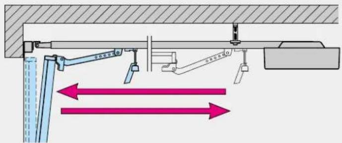
Figure 22.1
"CLOSE" potentiometer: maximum closing force.
This potentiometer allows you to set the maximum closing force that can be achieved. The factory pre-setting is the medium setting.
Increasing the force in the clockwise direction is only necessary for extremely sluggish doors.
Figure 22.2
"OPEN" potentiometer: maximum opening force.
This potentiometer allows you to set the maximum opening force that can be achieved. The factory pre-setting is the medium setting.
Increasing the force in the clockwise direction is only necessary for extremely sluggish doors.
Diagnosis LED: Error and status display
The diagnosis LED is located on the control unit circuit board (see fig. 12.1).
In its normal state the LED glows permanently and goes out when an impulse command is given.
LED display: flashes slowly
Possible cause: 1. STOP circuit interrupted
- STOP circuit open
Remedy: 1. Check wiring between terminals 4 and 5
- Close STOP switch
LED display: flashes 2x in 4 secs.
Possible cause: Closing safeguard is/was activated
-
8.2 kΩ resistor inserted between terminals 6 and 7?
-
Photocell or closing edge safety device interrupted or actuated
Remedy: 1. Connect 8.2 kΩ resistor to
terminals 6 and 7.
- Check photocell or closing edge safety device, if necessary replace.
LED display: flashes 3x in 5 secs.
Possible cause: 1. Closing force limit
Remedy: 1. Remove obstruction, if necessary delete door data and repeat procedure for putting into operation.
LED display: flashes 5x in 7 secs.
Possible cause: 1. Opening force limit
- Door spring broken
Remedy: 1. Remove obstruction, if necessary delete door data and repeat procedure for putting into operation.
LED display: flashes 6x in 8 secs.
Possible cause: 1. Operator or installation faulty
Remedy: 1. Delete door data, repeat procedure for putting into operation. Check wiring, if necessary replace operator.
LED display: flashes 7x in 9 secs.
Possible cause: 1. Operator has not yet been "taught"
Remedy: 1. Carry out "CLOSE" learn travel cycle
LED display: flashes 8x in 10 secs.
Possible cause: 1. Operator has not yet carried out any "OPEN" reference travel cycle
Remedy: 1. Carry out "OPEN" reference travel cycle
2.5 A/30 V DC 500 W/250 A DC
Ακροδέκτες 9-10
- Fio branco no borne 2 (Sinal)
- Fio castanho no borne 3 (+24V)
Ilustração 20
Indic. LED: pisca devagar
Over and above the statutory guarantee provided by the dealer's contract of purchase, we grant a guarantee for a period of 24 months from the date of purchase. Claims made under the guarantee do not extend the guarantee period. The guarantee period for replacement parts and repair work is 6 months, at least, however, the initial guarantee period.
Qualification
Guarantee claims are only applicable in the country where the product was purchased. The product must have been purchased through our authorized distribution channels. The guarantee only covers damage to the contract object itself. The receipt of purchase substantiates your right to claim under the guarantee.
Performance
During the guarantee period we undertake to rectify any and all faults on the product which can be proved to be attributed to a material or manufacturing defect. We pledge to provide free of charge and at our discretion, parts and service labour to repair or replace any part of the product that fails due to a manufacturing defect, to exchange the defective merchandise for faultless merchandise or to grant a reduction in price.
The guarantee does not cover damaged caused through:
- improper installation and connection
- improper use and operation
- external influences, such as fire, water, abnormal environmental conditions
- mechanical damage as a result of an accident, a fall, impact
- negligent or wanton destruction
- normal wear and tear
- repairs carried out by non-qualified persons
- using parts of another manufacturer
- removing the product number or making it unidentifiable
Any parts replaced under the guarantee become our property.