Liftronic 800 - Garage door Hormann - Free user manual and instructions
Find the device manual for free Liftronic 800 Hormann in PDF.
Frequently Asked Questions - Liftronic 800 Hormann
User questions about Liftronic 800 Hormann
0 question about this device. Answer the ones you know or ask your own.
Ask a new question about this device
Download the instructions for your Garage door in PDF format for free! Find your manual Liftronic 800 - Hormann and take your electronic device back in hand. On this page are published all the documents necessary for the use of your device. Liftronic 800 by Hormann.
USER MANUAL Liftronic 800 Hormann
TR10L006-C RE/11.2013
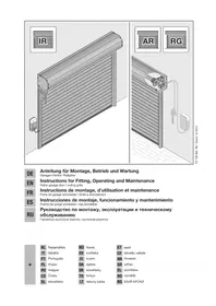
| DE | Anleitung für Montage, Betrieb und Wartung Garagentor-Antrieb |
| EN | Instructions for Fitting, Operating and Maintenance Garage door operator |
| FR | Instructions de montage, d'utilisation et d'entretien Motorisation de porte de garage |
| NL | Handleiding voor montage, werkung en onderhoud Garagedeuraandrijving |
| IT | Istruzioni per il montaggio, l'uso e la manutenzione Motorizzazione per portoni da garage |
| ES | Instrucciones de montaje, lavoramento y mantenimiento Automatismo para puertas de garaje |
| PT | Instruções de montagem, lavoramento e manutenção Automatismo para portas de garagem |
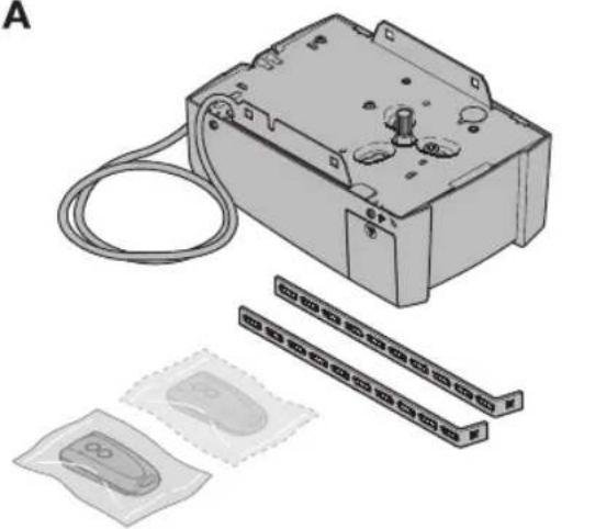
A
B
DEUTsCH 6
ENGLISH 21
FRANÇAIS 36
NEDERLANDS. 52
ITALIANO. 68
ESPANOL. 84
PORTUGUES. 100

114
(a) = Sectionaltor (b) = Schwingtor
| C1 | Extended fitting bracket If the clearance between the highest point of the door and the ceiling is less than 30 mm, the garage door operator can also be mounted behind the opened door if enough space is available. In the following cases, an extended fitting bracket must be used: - for a lintel with offset of 1,000 mm - for sectional doors (N tracks) up to 2,375 mm high - for sectional doors (L or Z tracks) up to 2,250 mm high - for up-and-over doors up to 2,750 mm high | |
| C2 | Fitting bracket for sectional doors For doors of other makes | |
| C3 | Hand transmitter RSC 2 (including hand transmitter holder) This hand transmitter works with a rolling code (frequency: 433 MHz) that changes with each sending procedure. The hand transmitter is equipped with two buttons, i.e. you can use the second button to open another door or turn on the outdoor lights if there is an optional receiver for it. | |
| C4 | Hand transmitter RSZ 1 This hand transmitter fits in a vehicle cigarette lighter. The hand transmitter works with a rolling code (frequency: 433 MHz) that changes with each sending procedure. | |
| C5 | Internal push button PB 3 The internal push button can be used to conveniently open and close your door from within the garage, turn on the light and block radio control. Including a 7 m connecting lead (2-wire) and fixing material. | |
| C6 | Radio code switch RCT 3b Up to 3 door operators can be wirelessly operated via impulse using the illuminated radio code switch. This does away with the time-consuming need to lay cables. | |
| C7 | Surface-mounted / recessed key switch You can use the key switch to operate the garage door operator from the outside with a key. Two versions in one device – surface-mounted or recessed. | |
| C8 | Emergency release lock NET 3 Necessary for garages without a second entrance. - Bore Ø13 mm - Cable length 1.5 m | |
| C9 | 100x | Receiver RERI 1 / RERE 1 This 1-channel receiver enables operation of a garage door operator with one hundred additional hand transmitters (buttons). Memory spaces: 100 Frequency: 433 MHz (Rolling Code) Operating voltage: 24 VAC/DC or 230/240 VAC Relay output: On/off |
| C10 | One-way photocell EL 101 For indoor use as additional safety device. Including 2×10 m connecting lead (2-wire) and fixing material. | |
| C11 | Extension set for the boom FS3 |
Table of Contents
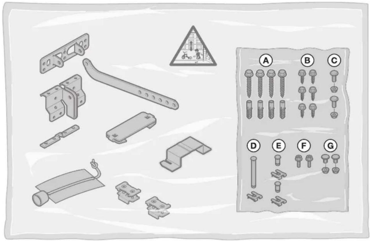
A Articles supplied 2
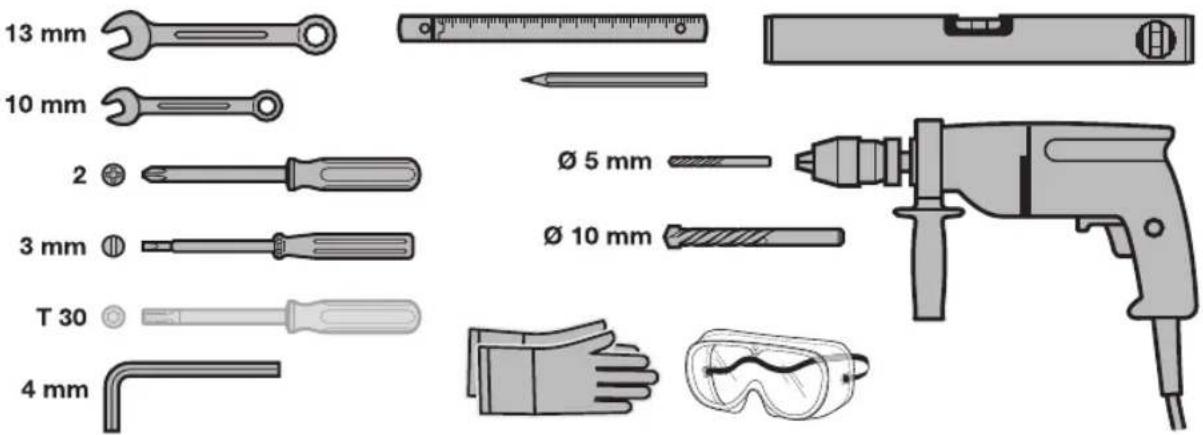
B Tools needed for fitting the garage door operator. 2
C Accessories for the garage door operator. 19
D Spare parts 128
1 About these Instructions 22
1.1 Further applicable documents.. 22
1.2Warnings used 22
1.3 Definitions used 22
1.4 Information on the illustrated section 22
1.5 Symbols used 22
2 Safety Instructions 23
2.1 Intended use 23
2.2 Inappropriate use 23
2.3 Fitter qualification 23
2.4 Safety instructions for fitting, maintenance, repairs and disassembly of the door system....23
2.5 Safety instructions for fitting 23
2.6 Safety instructions for initial start-up and for operation 23
2.7 Safety instructions for using the hand transmitter 24
2.8 Approved safety equipment 24
3 Fitting 24
3.1 Inspecting the door / door system 24
3.2 Clearance required 24
3.3 Preparation on a sectional door.. 24
3.4 Preparation on an up-and-over door 24
3.5Assembling the operator boom 25
3.6 Determining the door end-of-travel positions.....25
3.7 Fitting the garage door operator.. 25
3.8 Emergency release 25
3.9 Fixing the warning sign 25
4 Initial Start-Up / Connecting Additional Components 26
4.1 Display and control elements 26
4.2 Teaching in the operator 26
4.3 Connecting additional components/accessories 27
4.4 DIL switch functions 27
5 Radio 27
5.1 Hand transmitter RSC 2.28
5.2 Integral radio receiver 28
5.3 Teaching in hand transmitters.. 28
5.4 Operation 28
5.5 Deleting all memory spaces 28
6 Operation 28
6.1 Instructing users 29
6.2 Function tests 29
6.3 Normal operation 29
6.4 Behaviour during a power failure 29
6.5 Behaviour following a power failure 29
7 Inspection and Maintenance 30
7.1 Checking the tension of the toothed belt 30
7.2 Checking safety reversal/reversing 30
7.3 Exchanging the bulb 30
8 Displays for Operating Conditions, Errors andWarnings. 30
8.1Operator light messages.. 30
8.2 Display of error and warning messages 30
9 Deleting Door Data 31
10 Dismantling and Disposal 31
11 Warranty Conditions 32
12 Excerpt from the Declaration of Incorporation..32
13 Technical Data. 32
Illustrated section. 114
Dissemination as well as duplication of this document and the use and communication of its content are prohibited unless explicitly permitted. Noncompliance will result in damage compensation obligations. All rights reserved in the event of patent, utility model or design model registration. Subject to changes.
Dear customer,
We are delighted that you have chosen a high-quality product from our company.
1 About these Instructions
These instructions are original operating instructions as outlined in the EC Directive 2006/42/EC. Read through all of the instructions carefully, as they contain important information about the product. Pay attention to and follow the instructions provided, particularly the safety instructions and warnings.
Keep these instructions in a safe place for later reference!
1.1 Further applicable documents
The following documents must be available for safe handling and maintenance:
These instructions
The enclosed test manual
The garage door operating instructions
1.2 Warnings used
The general warning symbol indicates a danger that can lead to injury or death. In the text section, the general warning symbol will be used in connection with the caution levels described below. In the illustrated section, an additional instruction refers back to the explanation in the text.
DANGER Indicates a danger that leads directly to death or serious injuries.
WARNING Indicates a danger that can lead to death or serious injuries.
CAUTION Indicates a danger that can lead to minor or moderate injuries.
ATTENTION Indicates a danger that can lead to damage or destruction of the product.
1.3 Definitions used
DIL switches
Located under the side flap of the operator cover are switches for activating the operator functions.
Impulse sequence control
With each push of the button, the door is started against the previous direction of travel, or the motion of the door is stopped.
Learning runs
Door runs in which the forces necessary for door travel are taught in.
Normal operation
Door travel with the taught-in travel distances and forces.
Reference run
Door travel towards the OPEN end-of-travel position in order to set the home position.
Reversing cycle/safety reversal
Door travel in the opposite direction when the safety device or force limit is activated.
Travel
The distance the door takes to traverse from the OPEN end-of-travel position to the CLOSE end-of-travel position.
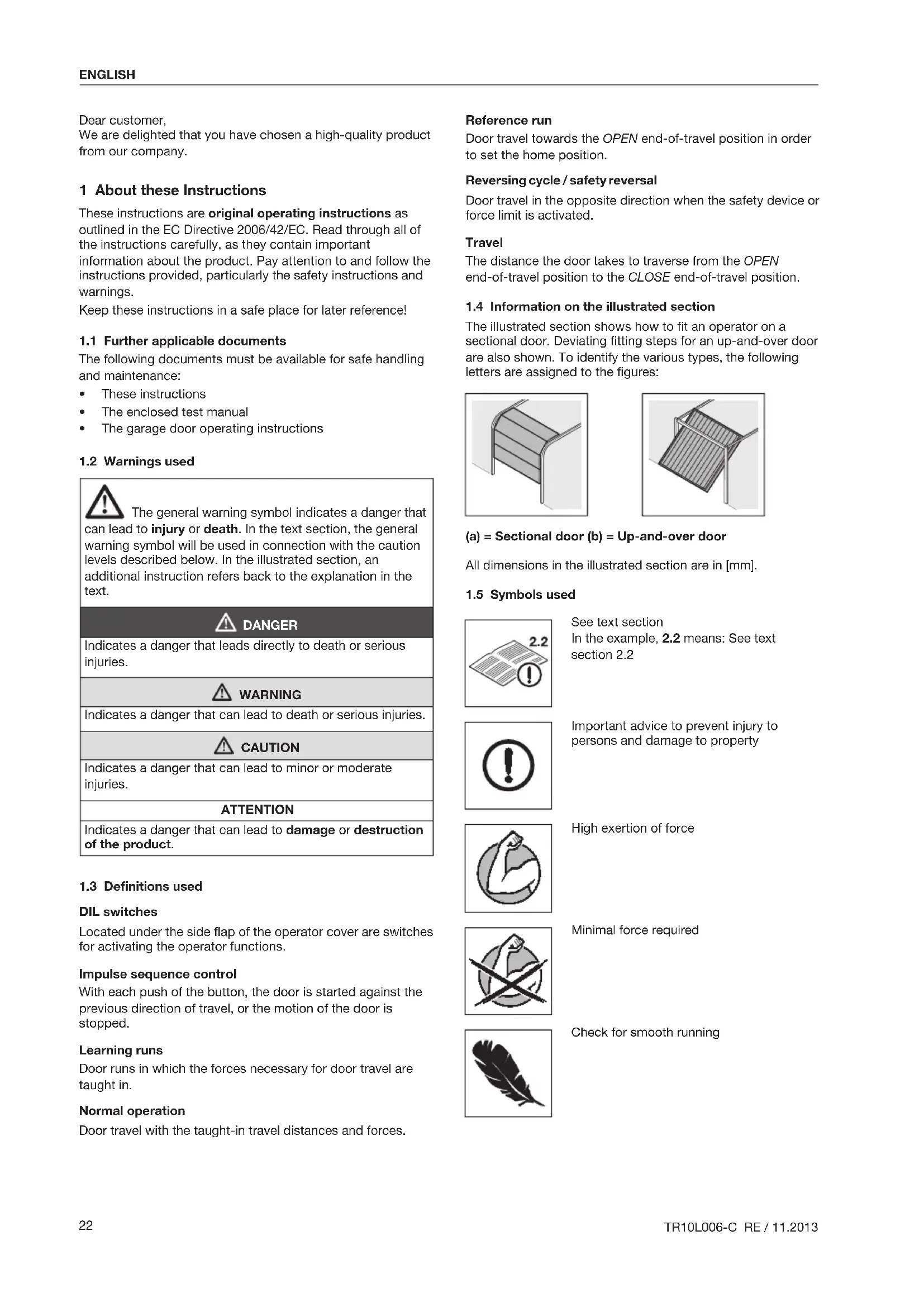
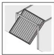
1.4 Information on the illustrated section
The illustrated section shows how to fit an operator on a sectional door. Deviating fitting steps for an up-and-over door are also shown. To identify the various types, the following letters are assigned to the figures:
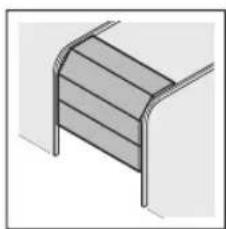
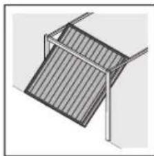
(a) = Sectional door (b) = Up-and-over door
All dimensions in the illustrated section are in [mm].
1.5 Symbols used
See text section
In the example, 2.2 means: See text section 2.2

Important advice to prevent injury to persons and damage to property

High exertion of force

Minimal force required

Check for smooth running

Use protective gloves

Audible engagement

DIL switch factory setting
2 Safety Instructions
2.1 Intended use
The garage door operator is intended exclusively for the impulse operation of spring-compensated sectional and up-and-over garage doors in the private/non-commercial sector.
Note the manufacturer's specifications regarding the door and operator combination. Potential hazards as outlined in DIN EN 13241-1 are avoided by construction and fitting according to our guidelines. Door systems that are located in a public area and only have one protective device, such as a force limit, may only be operated under supervision.
The garage door operator is designed for operation in dry areas.
2.2 Inappropriate use
Continuous operation and use in the commercial sector is prohibited.
The operator must not be used for doors without a safety catch.
2.3 Fitter qualification
Only correct fitting and maintenance in compliance with the instructions by a competent / specialist company or a competent/qualified person ensures safe and flawless operation of the system. According to EN 12635, a qualified person is a person with suitable training, specialist knowledge and practical experience sufficient to correctly and safely fit, test, and maintain a door system.
2.4 Safety instructions for fitting, maintenance, repairs and disassembly of the door system
Fitting, maintenance, repairs, and disassembly of the door system and garage door operator must be performed by a specialist.
In the event of a failure of the garage door operator, a specialist must be commissioned immediately for the inspection or repair work.
2.5 Safety instructions for fitting
The specialist carrying out the work must ensure that installation is conducted in compliance with the prevailing national job safety rules and regulations and those governing the operation of electrical equipment. The relevant national directives must be observed. Potential hazards as outlined in DIN EN 13241-1 are avoided by construction and fitting according to our guidelines.
The garage ceiling must guarantee secure fastening of the operator. For ceilings which are too high or too light, the operator must be fastened on additional struts.
2.6 Safety instructions for initial start-up and for operation
2.7 Safety instructions for using the hand transmitter

WARNING
Danger of injury during unwanted door travel
See warning in section 5

CAUTION
Danger of injury during unintended door travel
See warning in section 5
2.8 Approved safety equipment
Safety relevant functions or components of the control, such as the force limit, external photocells and closing edge safety device, have been designed and approved in accordance with category 2, PL "c" of EN ISO 13849-1:2008.

WARNING
Danger of injuries due to faulty safety equipment
See warning in section 4.2
3 Fitting
3.1 Inspecting the door / door system

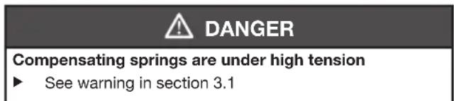
GEFAHR
Compensating springs are under high tension
Serious injuries may occur while adjusting or loosening the compensating springs!
For your own safety, only have a specialist conduct work on the door compensating springs and, if necessary, maintenance and repair work!
- Never try to replace, adjust, repair or reposition the compensating springs for the counterbalance of the door or the spring mountings yourself.
- Furthermore, inspect the entire door system (joints, door bearings, cables, springs and fastening parts) for wear and possible damage.
- Check for the presence of rust, corrosion, and cracks. A fault in the door system or an incorrectly aligned door may lead to serious injuries!
Do not use the door system if repair or adjustment work must be conducted!
The construction of the operator is not designed for operation with stiff doors, that is, doors that can no longer be opened or closed manually, or can only be opened / closed manually with difficulty.
The door must be in perfect mechanical condition, so that it is easy to operate by hand (EN 12604).
- Lift the door by approx. one metre and let it go. The door should stay in this position and neither move downward nor upward. If the door does move in either direction, there is a danger that the compensating springs / weights are not properly adjusted or are defective. In this case, increased wear and malfunctioning of the door system can be expected.
Check whether the door can be opened and closed correctly.
The mechanical locking devices of the door that are not needed with a garage door operator must be put out of commission. This especially includes the locking mechanisms of the door lock (see section 3.3.1 and section 3.4.1).
- Switch to the illustrated section and observe the respective text section when you are prompted to by the symbol for text reference.
3.2 Clearance required
See figure 1.1a/1.2b
The clearance between the highest point of door travel and the ceiling must be at least 30mm
If the clearance is smaller and enough space is available, then the operator can also be mounted behind the opened door. In such cases, an extended fitting bracket has to be used, which must be ordered separately (see Accessories for the garage door operator / C1).
The garage door operator can be arranged up to max. 50~cm off-centre. The electric socket necessary for the electrical connection should be fitted approx. 50~cm from the operator head (note section 4 Mains Voltage).
Check these dimensions!
3.3 Preparation on a sectional door

WARNING
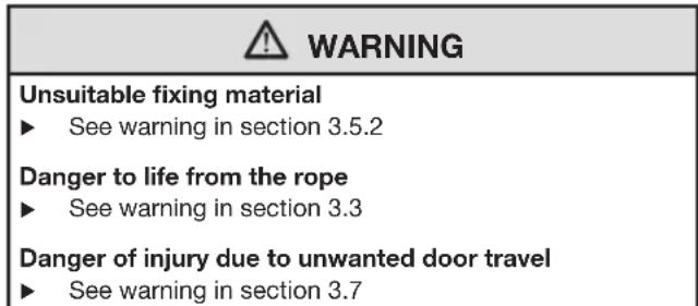
Danger to life from the rope
A running rope may lead to strangulation.
Remove the rope while fitting the operator (see figure 1.2a).
3.3.1 Door locking on the sectional door
See figure 1.3a
- Completely disassemble the mechanical door locking on the sectional door.
3.3.2 Off-centre reinforcement profile on a sectional door
See figure 1.5a
- With an off-centre reinforcement profile on the sectional door, fit the link bracket on the nearest reinforcement profile to the left or right.
3.3.3 Centre locking on a sectional door
See figure 1.6a
For sectional doors with centre door locking, arrange the lintel joint and link bracket max. 50~cm off-centre.
3.4 Preparation on an up-and-over door
3.4.1 Door locking on an up-and-over door
See figure 1.3b/1.4b/1.5b
- Render the mechanical door locking on the up-and-over door inoperable.
For door models not covered here, block the catches on site.
3.4.2 Up-and-over doors with an ornamental iron handle
See figure 1.6b
In a deviation from the illustrated section, attach the lintel ceiling console and link bracket max. 50~cm off-centre for up-and-over doors with ornamental iron door handles.
3.4.3 Up-and-over doors with timber infill
See figure 1.7b
For N 80 doors with timber infill, the bottom holes on the lintel joint must be used for fitting.
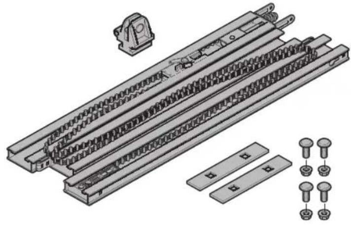
3.5 Assembling the operator boom
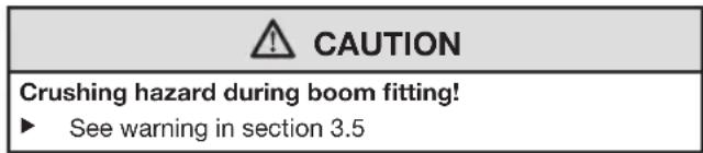
CAUTION
Crushing hazard during boom fitting!
There is a danger of crushing your fingers while fitting the operator boom.
Make sure that your fingers do not get between the profile ends.
Use the enclosed fitting instructions to install the boom.
Before assembling the last boom segment, place the boom in front of a stable surface (e.g. a wall) that can serve as a counter support.
- Check to see if the toothed belt is located on the centre of the return pulley. If it is not, shift the toothed belt to the centre using a blunt object (e.g. with the blunt end of a wrench).
Check the toothed belt tension and adjust if necessary (see figure 17 and section 7.1).
3.5.1 Checking that the slide carriage is easy to move
See figure 2.1
- Make sure that the individual boom segments are aligned with one another so that there are smooth transitions at each profile end!
- Check to make sure that the slide carriage can be easily moved in the boom. To do this, push the slide carriage back and forth in the boom once. Repeat this procedure, if necessary.
3.5.2 Fitting the operator boom
See figures 2.2-2.5
WARNING
Unsuitable fixing material
Use of unsuitable fixing material may mean that the operator is insecurely attached and could come loose.
The fitter must check that the fitting materials supplied are suitable for the purpose and the intended fitting location.
Only use the provided fixing materials (plugs) in concrete ≥ B15 (see figures 1.6a/1.8b/2.5).
ATTENTION
Damage caused by dirt
Drilling dust and chippings can lead to malfunctions.
Cover the operator during drilling work.
Before the boom is fitted on the lintel and under the ceiling, shift the slide carriage approx. 20~cm towards the middle of the boom. At a later point, this will no longer be possible!
3.6 Determining the door end-of-travel positions
See figure 3.1a/3.1b-5.2
- Assemble the fitting bracket.
-
Loosely insert the end stop for the OPEN end-of-travel position in the boom between the slide carriage and operator and manually push the door into the OPEN end-of-travel position. This will push the end stop into the correct position.
-
Tighten the end stop for the OPEN end-of-travel position.
- Loosely insert the end stop for the CLOSE end-of-travel position in the boom between the slide carriage and the lintel ceiling console and manually push the door into the CLOSE end-of-travel position.
This will push the end stop into the correct position.
- Tighten the end stop for the CLOSE end-of-travel position.
NOTE:
If the door cannot be easily pushed manually into the desired OPEN or CLOSE end-of-travel position, this means that the door mechanism is too stiff for operation with the garage door operator and must be inspected (see section 3.1)!
3.7 Fitting the garage door operator
See figure 6
WARNING
Danger of injury due to unwanted door travel
Incorrect assembly or handling of the operator may trigger unwanted door travel that may result in persons or objects being trapped.
Follow all the instructions provided in this manual. Incorrectly attached control devices (e.g. buttons) may trigger unwanted door travel. Persons or objects may be trapped as a result.
Install control devices at a height of at least 1.5m (out of the reach of children).
Fit permanently installed control devices (such as buttons, etc.) within sight of the door, but away from moving parts.
3.8 Emergency release
An emergency release lock for a mechanical release is required for garages without a second entrance in order to prevent users from locking themselves out in the case of a power failure (to be ordered separately, see Accessories for garage door operator C8).
Check the emergency release monthly for proper function.
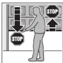
3.9 Fixing the warning sign
See figure 7
Fix the sign warning about getting trapped in a noticeable, cleaned and degreased place, for example, near to the permanently installed button for moving the operator.
4 Initial Start-Up/Connecting Additional Components
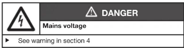
| 4 | DANGER |
| Mains voltage | |
| Contact with the mains voltage presents the danger of a deadly electric shock. For that reason, observe the following warnings under all circumstances: • Electrical connections may only be made by a qualified electrician. • The on-site electrical installation must conform to the applicable protective regulations (230/240 V AC, 50/60 Hz)! • If the mains connection cable is damaged, it must be exchanged by a qualified electrician to avoid danger. • The mains plug must be disconnected before any work is performed on the operator. | |
| 警告 WARNING |
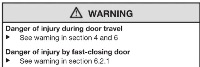
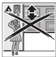
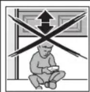
| Danger of injury during door travel If people or objects are in the area around the door while the door is in motion, this can lead to injuries or damage. • Make sure that children are not playing near the door system. • Make sure that no persons or objects are in the door's travel range. • If the door system has only one safety feature, only operate the garage door operator if you are within sight of the door's area of travel. • Monitor the door travel until the door has reached the end-of-travel position. • Only drive or pass through remote control door systems when the door is at a standstill! • Never stay standing under the open door. |
| CAUTION |
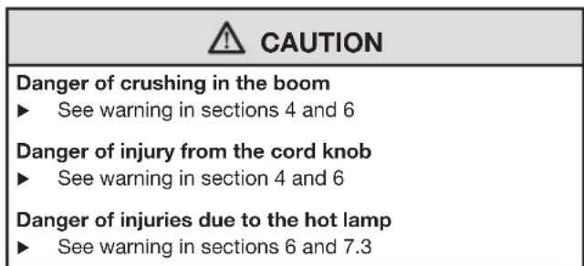
| Danger of crushing in the boom Do not reach into the boom with your fingers during door travel, as this can cause crushing. ► Do not reach into the boom during door travel. |
| CAUTION |
| Danger of injury from the cord knob If you hang on the cord knob, you may fall and injure yourself. The operator could break away and injure persons or damage objects that are located underneath, or the operator itself could be destroyed. ► Do not hang on the cord knob with your body weight. |
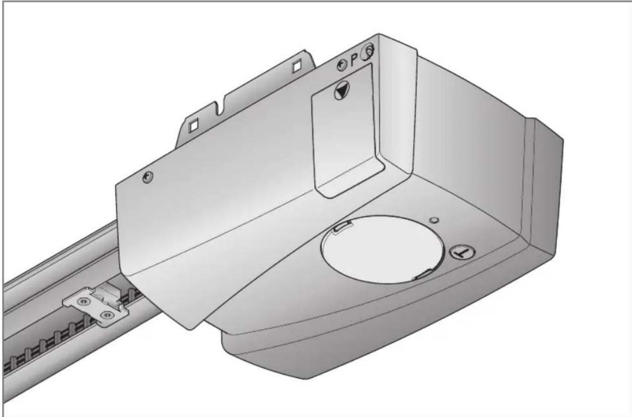
4.1 Display and control elements
| T button • Teaching in the operator (travel and forces needed) • Impulse button in normal operation | |
| P button • Teaching in the hand transmitter • Deleting the registered hand transmitters | |
| Red LED • Display of operating conditions • Display of error messages | |
| Operator light • Display of operating conditions • Garage light | |
| DIL switches • Activation of operator functions |
4.2 Teaching in the operator
See figures 8-9
Among other things, the door-related data such as the travel and forces needed during the opening and closing runs are taught in and saved in a power failure-proof manner during the teach-in process. This data is only valid for this door.
NOTE:
If connected, the photocell is not active during the teach-in process.
- Push the green button on the slide carriage.
- Move the door by hand until the slide carriage snaps into the belt lock.
- Plug in the mains plug. The operator light will flash two times.
-
Press the T button on the operator cover in order to start the learning runs.
-
The door will open and stop shortly in the OPEN end-of-travel position. The operator light will flash.
- The door will automatically open - close - open - close. In the process the travel and forces needed will be taught in. The operator light will flash.
- The door will stop in the OPEN end-of-travel position. The operator light will now light up continually and go out after approx. 2 minutes.
The operator has been taught in and is ready for operation.
- Check whether the door actually fully reaches its CLOSE and OPEN positions. If it does not, reposition the end stop accordingly, then delete the existing door data (see section 9) and teach in the operator again.
| WARNING |
| Danger of injuries due to faulty safety equipmentIn the event of a malfunction, there is a danger of injuries due to faulty safety equipment. |
| After the learning runs, the person commissioning the system must check the function(s) of the safety equipment. |
| The system is ready for operation only after this. |
4.3 Connecting additional
components/accessories
ATTENTION
External voltage on the connecting terminals
External voltage on the connecting terminals of the control will destroy the electronics.
Do not apply any mains voltage (230 / 240 V AC) to the connecting terminals on the control.
The terminals that the additional components are connected to, such as volt-free internal push buttons, key switches or photocells, only carry a non-hazardous low-voltage current of approx. 24 V DC.
To prevent malfunctions:
Duct the operator's connection cables (24 V DC) in an installation system that is separate from other supply lines (230/240 V AC).
4.3.1 Electrical connection/connecting terminals
See figure 10
- Remove the side flap on the operator cover in order to access the connecting terminals for additional components.
NOTE:
All connecting terminals can be given multiple assignments, but with a maximum of 1 × 1.5 ~mm^2 (see figure 11).
Loading of the operator by all accessories: max. 250 mA.
4.3.2 External buttons *
See example an for internal push button in figure 12
One or more buttons with normally open contacts (volt-free) can be connected in parallel.
4.3.3 2-wire photocell
NOTE:
Follow the fitting instructions when mounting photocells.
Connect the photocells as shown in figure 13.
After the photocell triggers, the operator stops and, after a short pause, a safety reversal of the door is performed to the OPEN end-of-travel position.
4.4 DIL switch functions
See figure 10
Several of the operator's functions must be programmed using the DIL switches. Before initial start-up, the DIL switches are in the factory settings, i.e. all the switches are in the OFF position.
NOTE:
Only change the DIL switch settings when the operator is at a rest and no radio codes are being programmed.
Set the DIL switches as described below in accordance with the national regulations, the desired safety equipment and the on-site conditions.
4.4.1 DIL switch A: activate 2-wire photocell
See figure 13
If the light path is interrupted during closure, the operator will stop immediately and, after a short pause, travel until it reaches the OPEN end-of-travel position.
| ON 2-wire photocell | |
| OFF | No safety device (delivery condition) |
4.4.2 DIL switch B: without function
5 Radio

WARNING
Danger of injury during unwanted door travel
Pressing a button on the hand transmitter may result in unwanted door cycles and cause injury.
Make sure that the hand transmitters are kept away from children and can only be used by people who have been instructed on how the remote-control door functions!
If the door has only one safety feature, only operate the hand transmitter if you are within sight of the door!
Only drive or pass through remote control door systems when the door is at a standstill!
Never stay standing under the open door.
- Please note that unwanted door cycles may occur if a hand transmitter button is accidentally pressed (e.g. if stored in a pocket/handbag).

CAUTION
Danger of injuries due to unintended door travel
Unwanted door travel may occur while teaching in the radio system.
Pay attention that no persons or objects are in the door's travel range when teaching in the radio system.
ATTENTION
Functional disturbances caused by environmental conditions
These conditions can impair function!
Protect the hand transmitter from the following conditions:
-
Direct sunlight (perm. ambient temperature: -20^ to +60^ )
-
Moisture
Dust
If there is no separate garage entrance, perform all teach-in processes, program changes and extensions while standing in the garage.
After teaching-in or extending the radio system, perform a function check.
- Only use original components when extending the radio system.
5.1 Hand transmitter RSC 2
The hand transmitter works with a rolling code that changes with each sending procedure. For this reason, it must be taught in with the desired hand transmitter button on each receiver that is to be controlled (see section 5.3 or the receiver's operating instructions).
5.1.1 Control elements
See figure 14
1 LED
2 Hand transmitter button
3 Battery
5.1.2 Inserting / changing the battery
See figure 14
Only use the battery type C2025, 3 V Li, and pay attention to the correct polarity.
5.1.3 Hand transmitter LED signals
LED illuminated:
The hand transmitter is sending a radio code.
LED flashing:
The hand transmitter is transmitting, but the battery charge is so low that it must be replaced soon.
No LED response:
The hand transmitter is not functioning.
- Check whether the battery has been inserted correctly.
- Exchange the battery for a new one.
5.1.4 Excerpt from the manufacturer's declaration
Conformity of the above-mentioned product with the requirements of the directives according to article 3 of the R&TTE directives 1999/5/EC was verified by compliance with the following standards:
EN300220-2
EN301489-3
EN50371
EN 60950-1
The original declaration of conformity can be requested from the manufacturer.
5.2 Integral radio receiver
The garage door operator is equipped with an integral radio receiver. A maximum of 6 different hand transmitter buttons can be taught in. If more are taught in, the first one will be deleted without advance warning. All memory spaces are empty in the delivery condition. They can only be taught in or deleted when the operator is at a standstill.
5.3 Teaching in hand transmitters
See figure 15
- Briefly press the P button on the operator cover. The red LED will begin to flash, signalling readiness for the teach-in process.
- Hold the desired hand transmitter button down until the LED begins flashing rapidly.
-
Release the hand transmitter button and press it again within 15 seconds until the LED begins flashing very rapidly.
-
Release the hand transmitter button.
The red LED remains lit and the hand transmitter button is taught in and ready for operation.
5.4 Operation
At least one hand transmitter button must be taught in on the radio receiver to operate the garage door operator via radio.
During radio transmission, the hand transmitter and receiver must be at least 1 m apart.
5.5 Deleting all memory spaces
See figure 16
It is not possible to delete individual memory spaces. The following step will delete all the memory spaces in the integral radio receiver (delivery condition).
- Press and hold the P button on the operator cover.
The red LED first flashes slowly and then becomes more rapid.
- Release the P button.
All memory spaces have now been deleted. The red LED will remain lit.
NOTE:
The deletion process will be aborted if button P is released within 4 seconds.
6 Operation

WARNING
Danger of injury during door travel If people or objects are in the area around the door while the door is in motion, this can lead to injuries or damage.
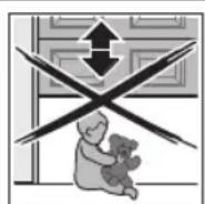
Make sure that children are not playing near the door system.
Make sure that no persons or objects are in the door's travel range.
If the door system has only one safety feature, only operate the garage door operator if you are within sight of the door's area of travel.
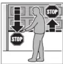
Monitor the door travel until the door has reached the end-of-travel position.
Only drive or pass through remote control door systems when the door is at a standstill!
Never stay standing under the open door.

CAUTION
Danger of crushing in the boom
Do not reach into the boom with your fingers during door travel, as this can cause crushing.
Do not reach into the boom during door travel.

CAUTION
Danger of injury from the cord knob
If you hang on the cord knob, you may fall and injure yourself. The operator could break away and injure persons or damage objects that are located underneath, or the operator itself could be destroyed.
Do not hang on the cord knob with your body weight.

CAUTION
Danger of injuries due to the hot lamp
Touching the lamp during or immediately following operation can lead to burns.
Do not touch the lamp if it is switched on or was recently switched on.
ATTENTION
Damage due to the cord of the mechanical release
If the cord of the mechanical release becomes caught on a roof carrier system or anything projecting from the vehicle or door, this can lead to damages.
Make sure that the cable cannot become caught.
NOTE:
As a general rule, conduct the initial function tests and the initial start-up or extension of the radio system inside the garage.
6.1 Instructing users
Instruct all persons who use the door system on the proper and safe use of the garage door operator.
Demonstrate and test the mechanical release as well as the safety reversal.
6.2 Function tests
6.2.1 Cord knob mechanical release

WARNING
Danger of injury by fast-closing door
If the cord knob is actuated while the door is open, there is a danger that the door will close rapidly if the springs are weak, broken or defective, or if the counterbalance is inadequate.
Only pull the cord knob when the door is closed.
Pull the cord knob when the door is closed. The door is now released and should be easy to open and close by hand.
6.2.2 Mechanical release by emergency release lock
(Only for garages without a second entrance)
- When the door is closed, actuate the emergency release lock.
The door is now released and should be easy to open and close by hand.
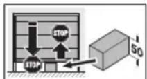
6.2.3 Safety reversal
To check the safety reversal:
- Stop the door with both hands while it is closing. The door system must stop and initiate the safety reversal.
- Stop the door with both hands while it is opening. The door system must switch off.
- Position a test object with a height of approx. 50~mm in the centre of the opening and close the door. The door system must stop and initiate the safety reversal as soon as it reaches the obstacle.
In the event of a failure of the safety reversal, a specialist must be commissioned immediately for the inspection and repair work.
6.3 Normal operation
In normal operation, the garage door operator works exclusively according to the impulse sequence control. It does not matter whether an external button, a hand transmitter button or the T button on the operator cover has been actuated:
1st impulse: The door runs towards an end-of-travel position.
2nd impulse: The door stops.
3rd impulse: The door runs in the opposite direction.
4th impulse: The door stops.
5th impulse: The door runs in the direction of the end-of-travel position selected in the 1st impulse.
etc.
The operator light will light up during a door run and go out after approx. 2 minutes.
6.4 Behaviour during a power failure
To be able to open or close the garage door by hand during a power failure, it must be disengaged from the slide carriage.
See figure 6.2.1 and 6.2.2
6.5 Behaviour following a power failure
After the power returns, the slide carriage must be re-engaged to the belt lock.
- Move the belt lock close to the slide carriage.
- Push the green button on the slide carriage.
- Move the door by hand until the slide carriage snaps into the belt lock.
- Check whether the door completely reaches its open and closed positions by conducting multiple uninterrupted door runs.
Now, the operator is ready for normal operation again.
For safety reasons, the door will always open upon the first impulse command after a power failure during a door run.
NOTE:
If the behaviour does not correspond to that described in step 4, even after multiple uninterrupted door runs, a new learning run is necessary. First the existing door data must be deleted (see section 9 and 4.2).
7 Inspection and Maintenance
The garage door operator is maintenance-free.
In the interest of your own safety, we recommend having the door system inspected and maintained by a qualified person in accordance with the manufacturer's specifications.

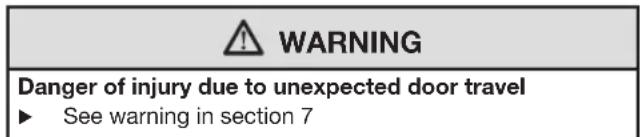
WARNING
Danger of injury due to unexpected door travel
Unexpected door travel can result during inspection and maintenance work if the door system is inadvertently actuated by other persons.
Pull out the mains plug and, if applicable, the plug of the emergency battery when performing all work on the door system.
- Safeguard the door system against being switched on again without authorization.
An inspection or necessary repairs may only be carried out by a qualified person. Contact your supplier for this purpose.
A visual inspection may be carried out by the operator.
Check all safety and protective functions monthly.
- Malfunctions and / or defects at hand must be rectified immediately.
7.1 Checking the tension of the toothed belt
Check the tension of the toothed belt every six months and adjust if necessary (see figure 17).
During the start-up and slow-down phase, it is possible that the belt will briefly hang out of the boom profile. However, this does not result in any technical consequences and does not negatively affect the function and service life of the operator.
7.2 Checking safety reversal/reversing
To check safety reversal / reversing:
- Stop the door with both hands while it is closing. The door system must stop a initiate the safety reversal.
- Stop the door with both hands while it is opening.
The door system must switch off.
- Position a test object with a height of approx. 50~mm in the centre of the opening and close the door. The door system must stop and initiate the safety reversal as soon as it reaches the obstacle.
In the event of a failure of the safety reversal, a specialist must be commissioned immediately for the inspection and repair work.
7.3 Exchanging the bulb
See figure 18

CAUTION
Danger of injuries due to the hot lamp
Touching the lamp during or immediately following operation can lead to burns.
Do not touch the lamp if it is switched on or was recently switched on.
When changing the bulb, it must be cold and the door closed.
Bulb type:
Depending on operator type)
10 W/24 V/B(a)15s
21 W/24 V/B(a) 15s
To change the bulb:
- Disconnect the mains plug.
- Change the bulb.
- Plug in the mains plug. The operator light will flash four times.
8 Displays for Operating Conditions, Errors andWarnings
8.1 Operator light messages
If the mains plug is plugged in without the T button having been pushed, the operator light will flash two, three or four times.
Two flashes
No door data is present or the door data has been deleted (delivery condition); it can be taught in immediately.
Three flashes
Saved door data is present, but the last door position is not sufficiently known. The next run will be an OPEN reference run. Afterwards, normal door runs will follow.
Four flashes
Saved door data is present and the last door position is sufficiently know, i.e. normal door runs can proceed immediately (normal behaviour after a successful teach-in and a power failure).
8.2 Display of error and warning messages
(Red LED on the operator cover)
The red LED helps to easily identify causes when operation does not go according to plan. In normal operation, the LED lights up continually.
NOTE:
If normal operation of the garage door operator with the radio receiver or the T button is otherwise possible, a short circuit in the external button's connecting lead or in the button itself can be recognised through the behaviour described here.
LED Flashes constantly
Cause The operator is in the Holiday function, the radio is locked by an internal push button (this is only a message and not a malfunction).
Remedy Press the locking key on the internal push button.
LED Flashes 2x
Cause A connected photocell was interrupted or actuated. A safety reversal may have occurred.
Remedy Eliminate the obstruction cause and / or check the photocell and replace if necessary.
Acknowledgement Renewed impulse entry by means of an external button, a hand transmitter button or the T button. In the OPEN end-of-travel position a closing run will take place, otherwise an opening run.
LED Flashes 3x
Cause The CLOSE force limit has been activated; a safety reversal took place.
Remedy Remove the obstruction. If the safety reversal took place for no apparent reason, check the door mechanism or the tension of the toothed belt. If necessary, delete the door data (see section 9) and teach it in again (see section 4.2) or adjust the tension of the toothed belt (see section 7.1).
Acknowledgement Renewed impulse entry by means of an external button, a hand transmitter button or the T button. An opening run will take place.
LED Flashes 5x
Cause The OPEN force limit has been activated. The door was stopped during an opening run.
Remedy Remove the obstruction. If the door stopped before the OPEN end-of-travel position for no apparent reason, check the door mechanism or the tension of the toothed belt.
If necessary, delete the door data (see section 9) and teach it in again (see section 4.2) or adjust the tension of the toothed belt (see section 7.1).
Acknowledgement Renewed impulse entry by means of an external button, a hand transmitter button or the T button. A closing run will take place.
LED Flashes 6x
Cause Operator error / malfunction in operator system
Remedy If necessary, delete the door data (see section 9) and teach it in again (see section 4.2). If the operator error occurs again, replace the operator.
Acknowledgement Renewed impulse entry by means of an external button, a hand transmitter button or the T button. An opening run will take place (OPEN reference run).
LED Flashes 7x
Cause The operator has not been taught in yet (this is only a message and not a malfunction).
Remedy/ Trigger the learning run by an external acknowledged- button, a hand transmitter button or gement the T button.
LED Flashes 8x
Cause The operator requires an OPEN reference run (this is only a message and not a malfunction).
Remedy/ Trigger the OPEN reference run by an acknowledged- external button, a hand transmitter gement button or the T button.
Note This is the normal status after a power failure if no door data is present or has been deleted and / or the last door position is not sufficiently known.
9 Deleting Door Data
See figure 19
If it is necessary to teach in again, the door data can be deleted as follows:
- Disconnect the mains plug.
- Press and hold the T button on the operator cover.
- Connect the mains plug and keep the T button pushed until the operator light flashes once.
It can now be taught in again. This is signalled by the red LED flashing 8 times.
NOTE:
You can read more about operator light messages (repeated flashing when the mains plug is plugged in) in section 8.1.
10 Dismantling and Disposal
NOTE:
When disassembling, observe the applicable regulations regarding occupational safety.
Have a specialist dismantle the garage door operator in the reverse order of these instructions and dispose of it properly. Contact your supplier for this purpose.
11 Warranty Conditions
Warranty
We shall be exempt from our warranty obligations and product liability in the event that the customer carries out his own structural alterations or undertakes improper installation work or arranges for same to be carried out by others without our prior approval and contrary to the fitting guidelines we have provided. Moreover, we shall accept no responsibility for the inadvertent or negligent use of the operator nor improper maintenance of the operator and the accessories, as well as for improper maintenance of the door and its counterbalance. Batteries and light bulbs are also not covered by the warranty.
Warranty period
In addition to the statutory warranty provided by the dealer in the purchase contract, we grant the following warranty from the date of purchase:
4 years or
5 years (depending on operator type)
2 years on radio equipment and accessories
Claims made under the warranty do not extend the warranty period. For replacement parts and repairs the warranty period is six months or at least the remainder of the warranty period.
Prerequisites
A claim under this warranty is only valid for the country in which the equipment was bought. The product must have been purchased through our authorised distribution channels. A claim under this warranty exists only for damage to the object of the contract itself. Reimbursement of expenditure for dismantling and fitting, testing of corresponding parts, as well as demands for lost profits and compensation for damages, are excluded from the warranty.
The receipt of purchase substantiates your right to claim under the warranty.
Performance
For the duration of the warranty we shall eliminate any product defects that are proven to be attributable to a material or manufacturing fault. We pledge to replace free of charge and at our discretion the defective goods with non-defective goods, to carry out repairs, or to grant a price reduction.
Damages caused by the following are excluded:
- improper fitting and connection
- improper initial start-up and operation
external factors such as fire, water, abnormal environmental conditions
mechanical damage caused by accidents, falls, impacts - negligent or intentional destruction
normal wear or deficient maintenance - repairs conducted by unqualified persons
use of non-original parts - removal or defacing of the product number
Replaced parts become the property of the manufacturer.
12 Excerpt from the Declaration of Incorporation
(as defined in EC Machinery Directive 2006/42/EC for incorporation of partly completed machinery according to annex II, part B)
The product described on the reverse side has been developed, constructed and produced in accordance with the following directives:
EC Machinery Directive 2006/42 EC
EC Construction Products Directive 89/106/EEC
EC Low-Voltage Directive 2006/95/EC
EC Electromagnetic Compatibility Directive 2004/108/EC
Applied and consulted standards and specifications:
EN ISO 13849-1, PL "c", Cat. 2
Safety of machinery - Safety-related parts of control systems - Part 1: General principles
EN 60335-1/2, when applicable
Safety of electrical appliances / Operators for doors
EN 61000-6-3
Electromagnetic compatibility - Electromagnetic radiation
EN 61000-6-2
Electromagnetic compatibility - Interference immunity
Partly completed machinery as defined in the EC Directive 2006/42/EC is only intended to be incorporated into or assembled with other machinery or other partly completed machinery or equipment, thereby forming machinery to which this directive applies.
This is why this product must only be put into operation after it has been determined that the entire machine / system in which it will be installed corresponds with the guidelines of the EC directive mentioned above.
Any modification made to this product without our express permission and approval shall render this declaration null and void.
13 Technical Data
| Mains voltage 230/240V, 50/60 Hz, | |
| Stand-by Approx. 6 W | |
| Mains voltage type Y | |
| Protection category Only for dry rooms | |
| Temperature range -20°C to +60°C | |
| Automatic safety cut-out | Is automatically taught in for both directions separately. |
| End-of-travel position cut-out/Force limit | • Self-learning • Wear-free, as it is designed without mechanical switches • Additionally integrated run time limit of approx. 45 s • Automatic safety cut-out, readjusting at every door run. |
| Rated load See data label | |
| Pull and push force See data label | |
| Motor Direct current motor with hall sensor | |
| Transformer with thermal protection | |
| Connection technology | • Simple screw terminal • Max. 1.5 mm² • For internal and external buttons with impulse operation |
| Special functions • | Operator light, 2-minute light • 2-wire photocell can be attached |
| Mechanical release A | Actuated from inside with pull cord in the event of a power failure |
| Remote control With | 2-button hand transmitter RSC 2 (433 MHz) and integral radio receiver with 6 memory spaces |
| Universal fittings For | up-and-over doors and sectional doors |
| Door travel speed Ap | prox. 13.5 cm per second (depending on the door type, the door size and the door leaf weight) |
| Airborne sound emission of the garage door operator | The equivalent continuous sound pressure level of 70 dB (A-weighted) is not exceeded at a distance of three metres. |
| Operator boom • Extremely flat (30 mm) • Three-part • With maintenance-free, patented toothed belt | |
| Use • Exclusively for | private garages • For easy to move up-and-over and sectional doors with a door area of up to: 9 m²/12.5 m² (depending on operator type) • Not approved for industrial / commercial use. |
1 Over dele handleiding. 53
LED knippert constant
Vedere figure 1.1a/1.2b
(a) = Puerta sectional (b) = Puerta basculante
5 Radiofrequency. 107
5.1 Emissor RSC 2. 107
5.2 Receptor de radiofrequency integrado 108
5.3 Ajuste dos emissores. 108
5.4 Funcionamento 108
5.5 Anulacao de todas as posicaoes de memoria 108
Verifique as dimensoes!
3.3 Preparacao na porta sectional