USER MANUAL ThermoSafe ThermoCarbon Hormann
1 About These Instructions. 10
1.1 Warnings used.. 10
1.2 Symbols used 10
1.3 Abbreviations used 12
1.4 Colour code for leads, single wires and components 12
2 Safety Instructions. 12
2.1 Fitter qualification 12
3 Fitting 12
3.1 Accessories 12
3.2 Determining the door position 13
3.3 Fitting types 13
3.4 Connection to building structure 13
3.5 Adjusting the fitting.. 13
3.6 Glazing 13
3.7 Electrical connections.. 13
3.8 Fitting break-in-resistant door sets. 13
4 Description of S5 Smart, Comfort, Code, Scan. 14
4.1 LED display 14
4.2 Teaching in a radio code.. 15
4.3 Teaching in a radio code 15
4.4 Operation 15
4.5 Reset 15
5 Inspection and Maintenance 15
5.1 Checking the seating and sealing.. 15
6 Cleaning and Care 15
6.1 Surface 15
6.2 Movable fitting parts 15
6.3 Door hinges 15
6.4 Cylinder 15
7 Dismantling and Disposal 15
8 Spare Parts. 15
79
Dissemination as well as duplication of this document and the use and communication of its content are prohibited unless explicitly permitted. Noncompliance will result in damage compensation obligations. All rights reserved in the event of patent, utility model or design model registration. Subject to changes.
Dear customer,
We are delighted that you have chosen a high-quality product from our company.
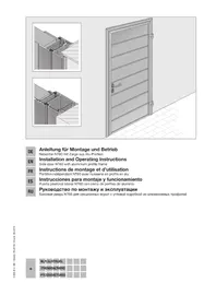
1 About These Instructions
These instructions are divided into a text section and an illustrated section. The illustrated section can be found after the text section.
These instructions are original instructions as outlined in the EU-BpVO 305/2011. Please read and follow these instructions. They contain important information on the installation, operation and proper care and maintenance of the aluminium entrance door so that you can enjoy the use of this product for many years.
Please pay particular attention to all safety and warning notices. Keep these instructions in a safe place for later reference!
Skilled fitting and thorough maintenance increase performance, availability and safety.
The texts and diagrams in this manual have been created with the greatest care possible. In order to provide a concise overview, not all detailed information on all variants and possible assemblies can be described. The texts and diagrams published in this manual are merely intended as examples.
Any guarantee for its completeness is excluded and does not justify a complaint.
Should you desire more information, or if special problems occur which are not described in detail in the manual, you may request information from the manufacturing plant.
Theift Rosenheim installation tool also provides further support. www.ift-rosenheim.de /ift-installation-tool
These instructions are an important document for the construction file.
1.1Warnings used
DANGER
Indicates a danger that leads directly to death or serious injuries.
ATTENTION
Indicates a danger that can lead to damage or destruction of the product.
1.2 Symbols used

Important note for avoiding damage to property

Permissible arrangement or activity

Non-permissible arrangement or activity

See text section
See illustrated section

See separate Fitting Instructions for the control or for the additional electrical control elements
Electrical voltage
Optional components, to be ordered as accessories
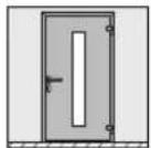
Single - leaf door

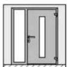
Door with side element
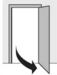
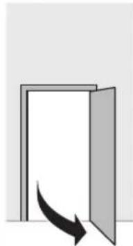
Door opening inwards
Door opening outwards

Support blocks
Spacing blocks
Position the frame to the leaf
House interior
House exterior

Not permissible according to DIN 4108
Winter
Summer
Condensation
Tighten the screws by hand
Tighten the screws firmly
Inspect

Maintenance-free
Placing door leaf on the floor
Remove and dispose of component or packaging
In the illustrated section, this indicates work steps that must be performed in succession
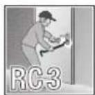
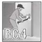
Break-in-resistant component RC 3 acc. to DIN EN 1627:2011
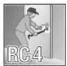
Break-in-resistant component RC 4 acc. to DIN EN 1627:2011
Attack side
Permanently open
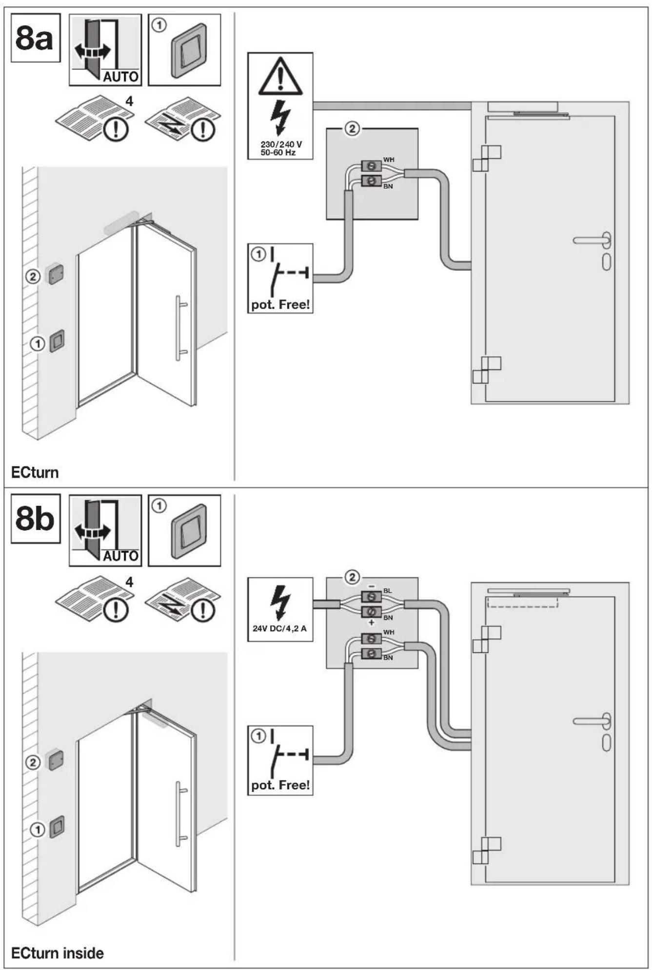
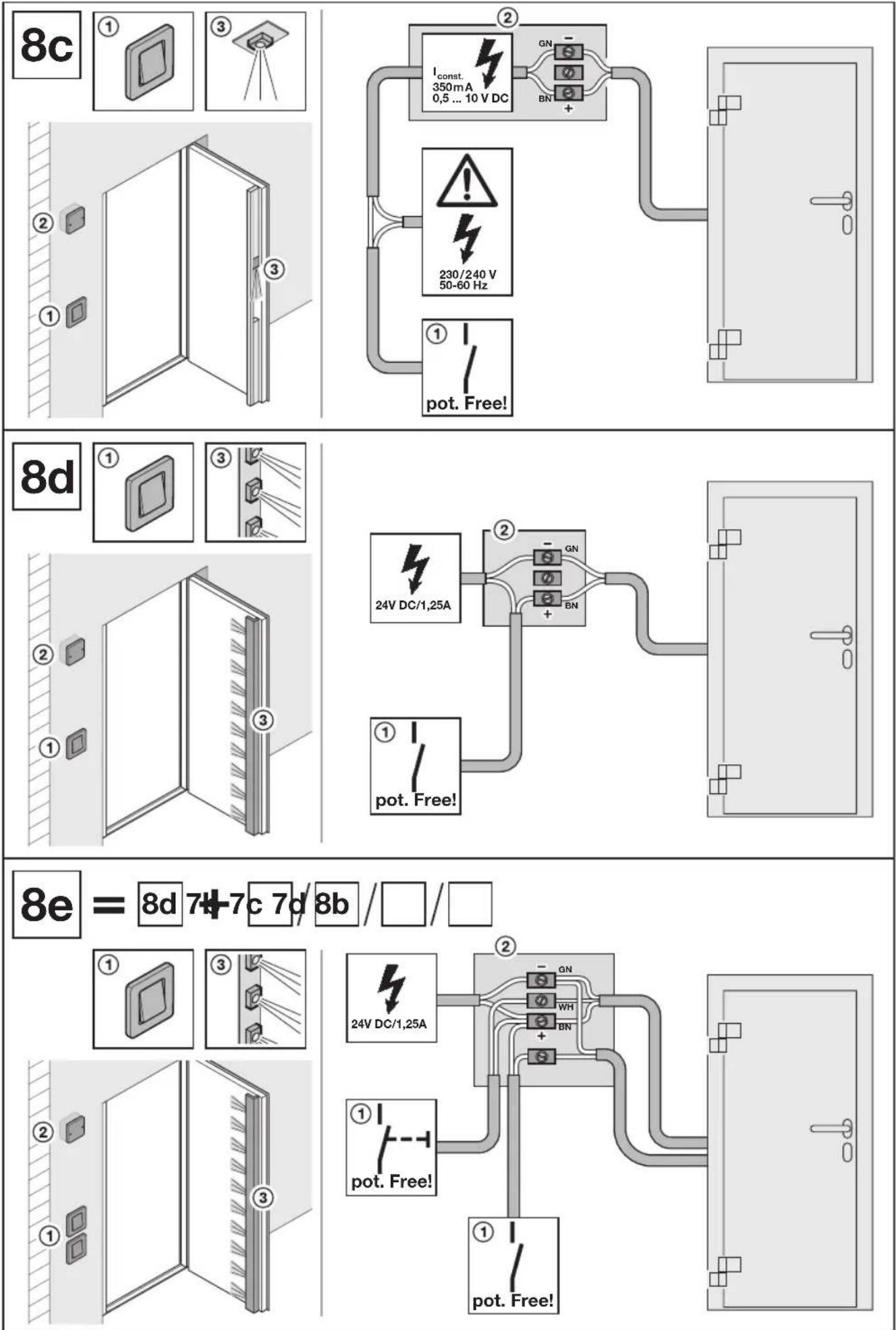
Volt-free contact
Switch
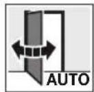
Automatic door
To be connected, fitted on-site
To be connected, fitted at the factory


1.3 Abbreviations used
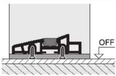
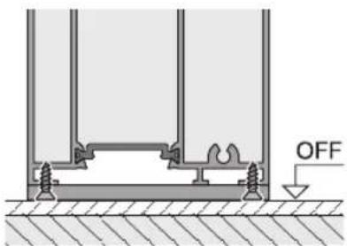
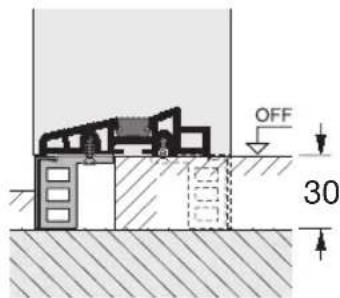
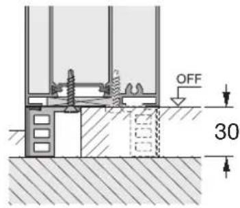
OFF (FFL) Finished floor level
1.4 Colour code for leads, single wires and components
The colour abbreviations for lead, wire and component identification follows the international colour code in accordance with IEC 757:
| BK black YE yellow | | |
| BN brown WH white | | |
| GN green GN/YE green/yellow | | |
| GY grey | | |
2 Safety Instructions
DANGER
Danger to life while fitting the entrance door
During fitting, the door or door frame can fall and kill persons.
Prior to and during fitting, secure the door and frame against falling over.
- Comply with the basic rules in DIN 4108 Thermal insulation and energy economy in buildings when fitting the aluminium entrance door.
Make sure to comply with the applicable standards, directives, regulations, ordinances and the generally accepted rules of technology.
- Protect your door until construction is completed by covering it with foil and tape to avoid damages. But keep in mind that tape can leave residue or damage to the coating, especially under prolonged exposure to the sun.
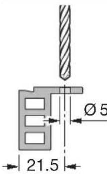
Identify suitable fastenings according to the local conditions and have them on hand.
- Anchor the aluminium entrance door at all of the provided fixing points in the wall.
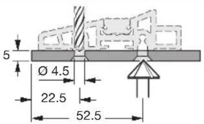
Always maintain the required edge and centre line spacing of the plugs depending on wall type, as well as the fitting information and handling guidelines of the plug manufacturer!
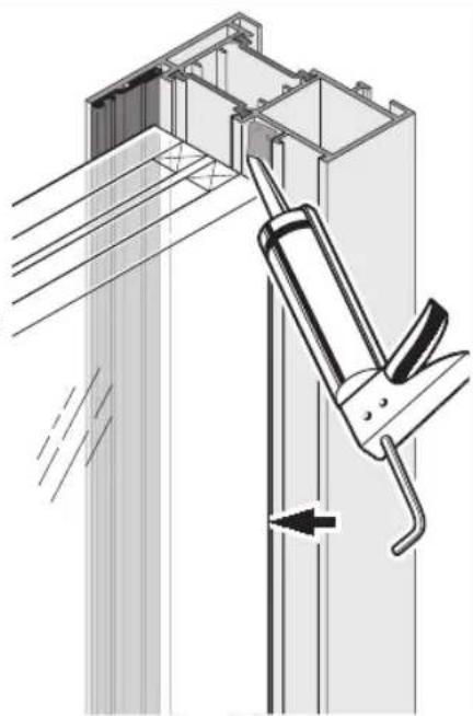
- Contact surfaces to be sealed with silicon and sealant material must first be cleaned, such as
-
Profile surfaces
-
Edge compound of the pane
-
Only use adhesive and sealant materials that are suitable for this application and compatible with the product materials. Follow the handling guidelines of the respective manufacturer.
- Electrical work may only be carried out by qualified electricians.
- EC Directive 2006/42/EC is to be complied with for aluminium entrance doors with automatic door operators.
2.1 Fitter qualification
In order to ensure proper installation of the aluminium entry door, only assembly technicians with commensurate training may be charged with the task.
ATTENTION
Impaired function
Missing or modified components will impair the function of the entrance door.
Do not alter or remove any components.
Fasten all components described in the manual.
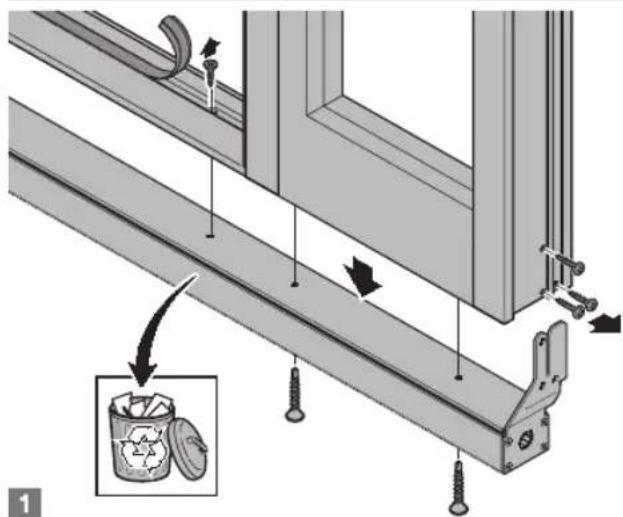
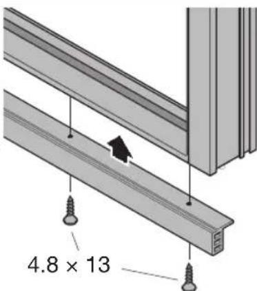
3 Fitting
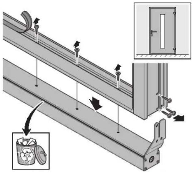
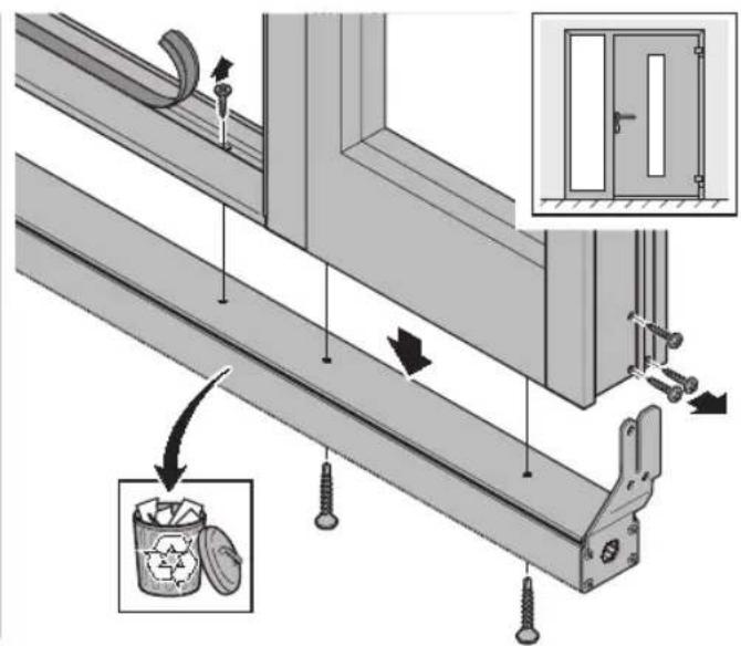
To ensure simple and professional fitting, carefully go through all the work steps shown in the illustrated section.
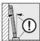
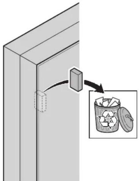
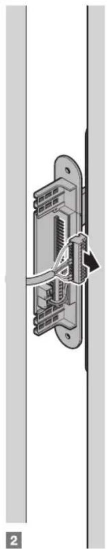
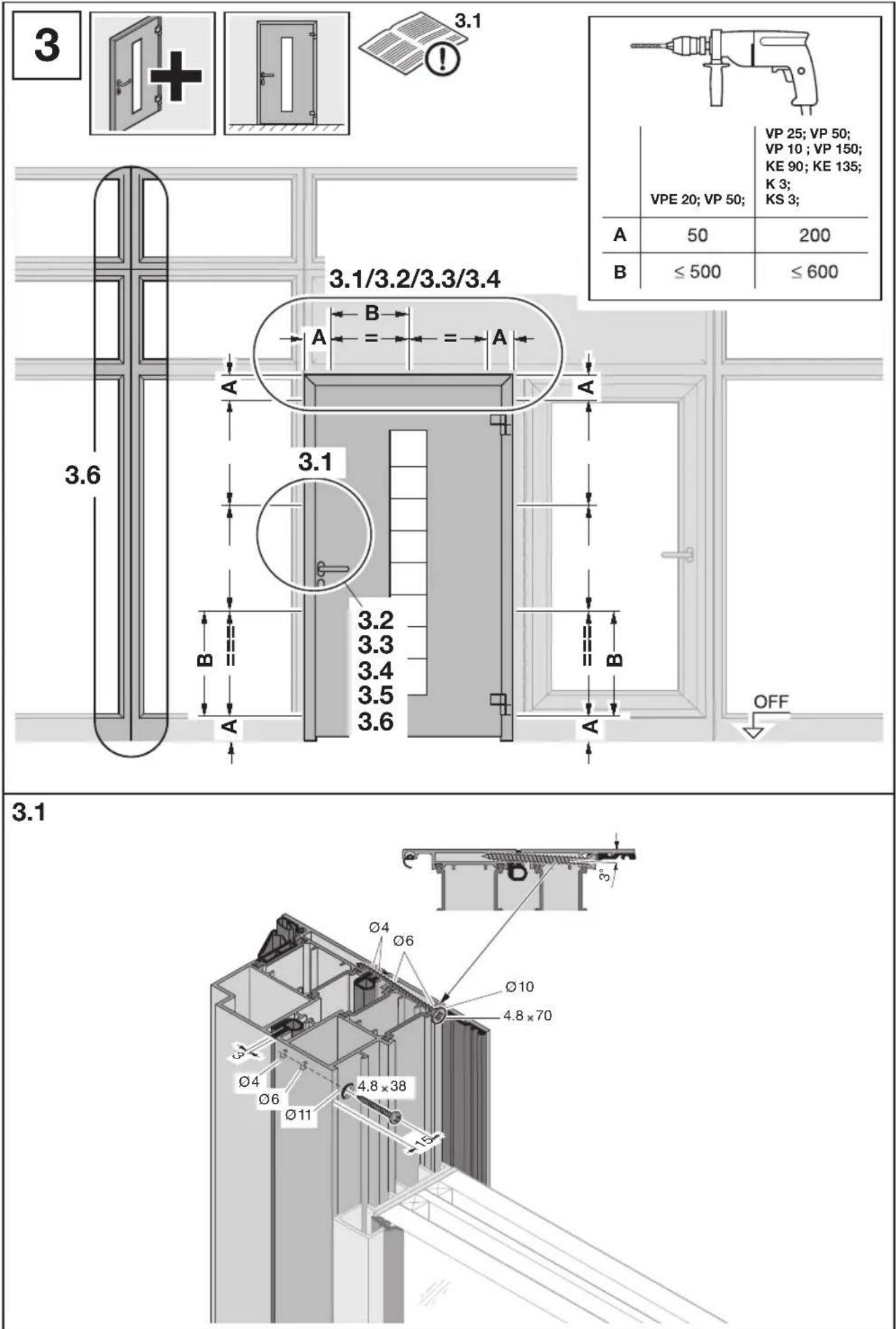
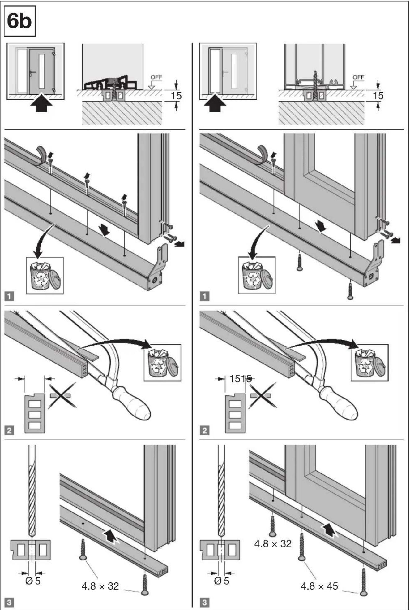
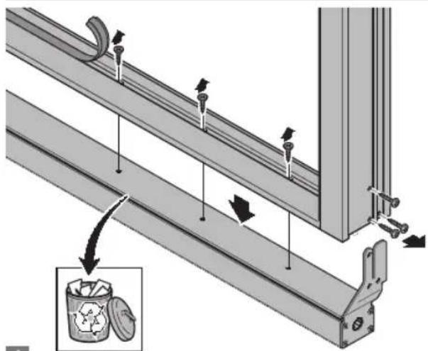
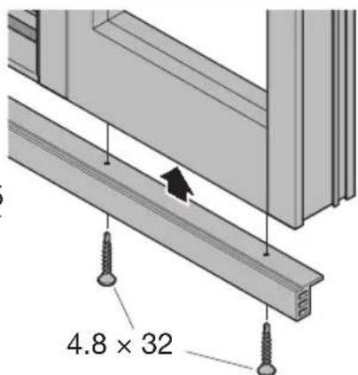
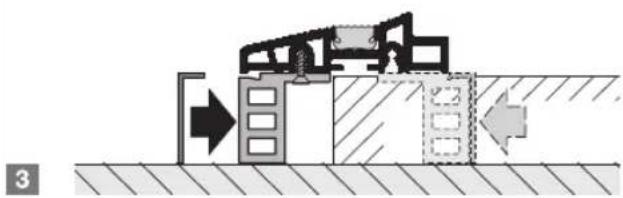
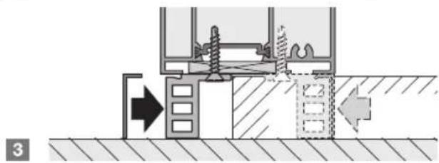
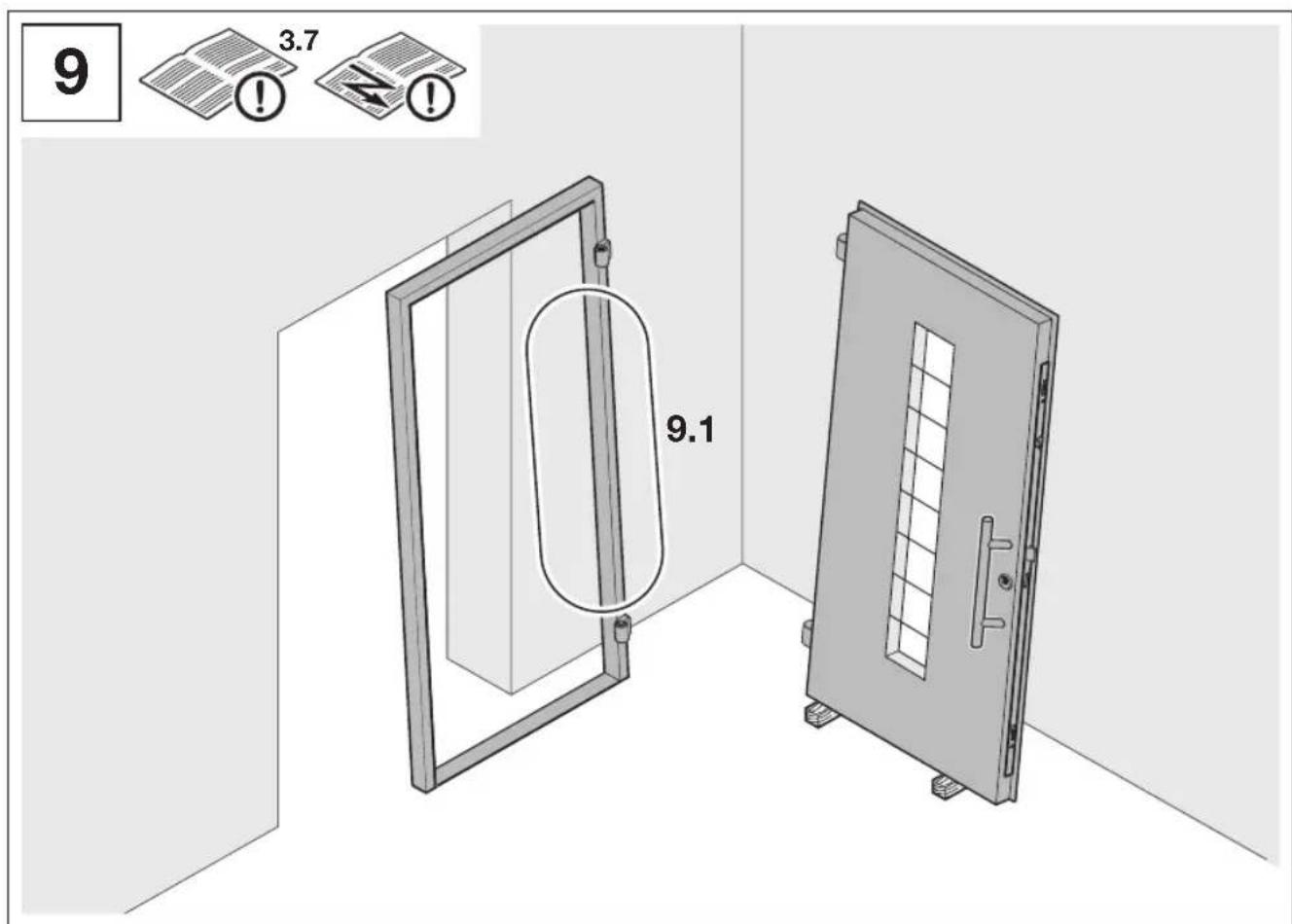
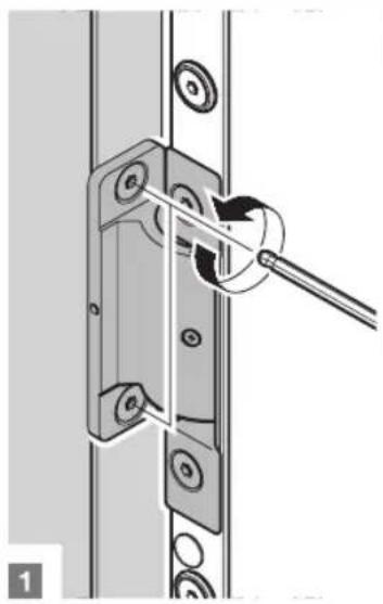
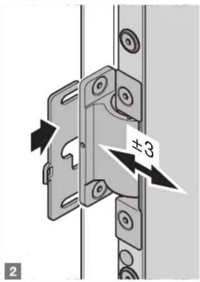
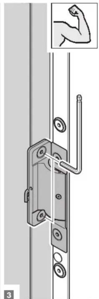
Before fitting the door, check whether any attached parts have to be fitted (see Figure 3).
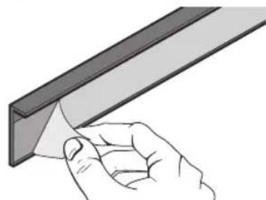
Remove the transport protection before fitting (see Figure 2.3).
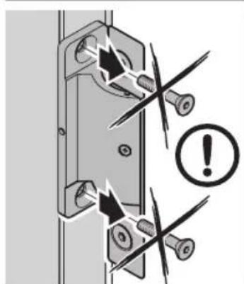
Fastening and sealing materials are not included in the scope of delivery.
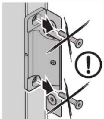
NOTE:
It is important that you use the fixing points prepared at the factory.
The fixing points indicated in the fitting instructions are only general and may deviate from the fixing points prepared at the factory.
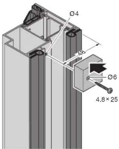
3.1 Accessories
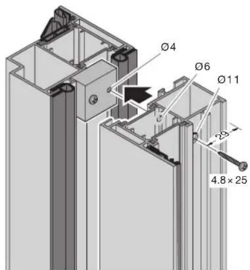
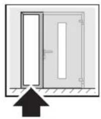
K3 door, side element, transom light (see Figures 3.1/3.2)
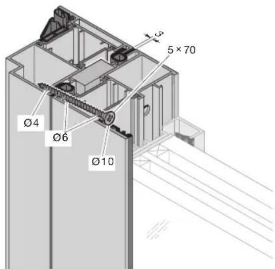
VP25/VP50 extension (see Figure 3.3a)
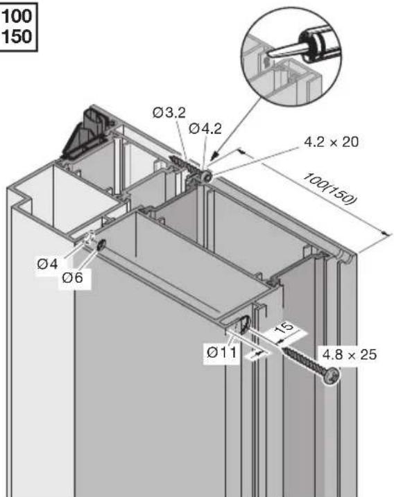
VP100/VP150 extension (see Figure 3.3b)
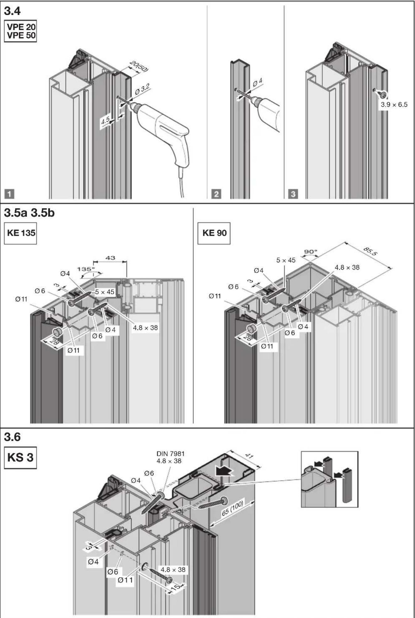
VPE20 / VPE50 one-piece extension (see Figure 3.4)
KE135/KE90 corner profiles 135^ / 90^ (see Figures 3.5a/3.5b)
KS3 static profile (see Figure 3.6)
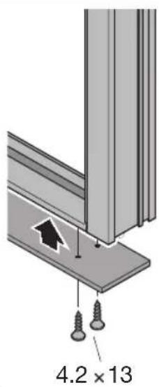
Fixing material for accessories is part of the scope of delivery.
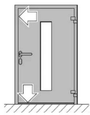
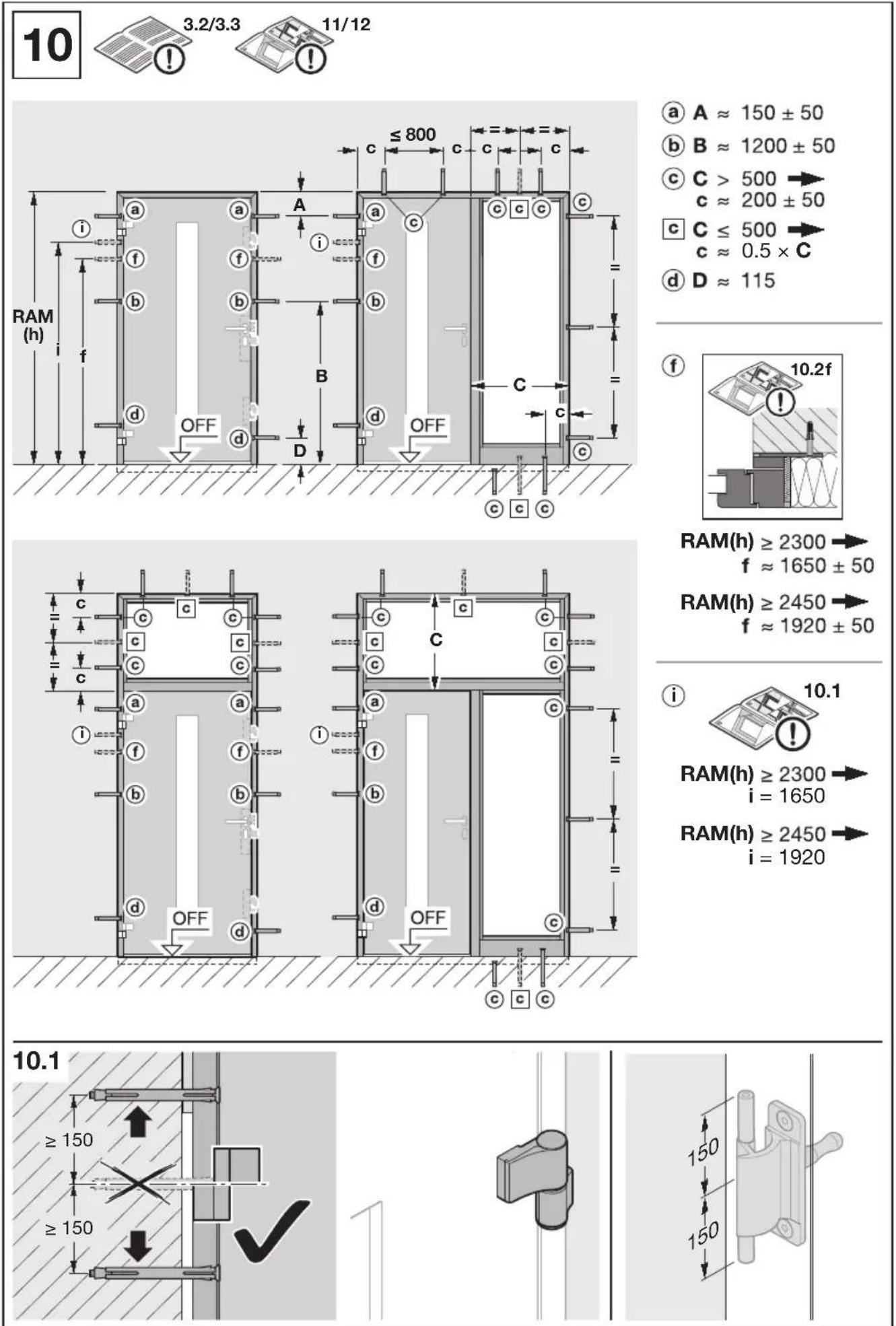
3.2 Determining the door position
Determine the door position depending on the on-site fastening options, type of wall and the required edge and centre line spacing for the plug.
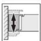
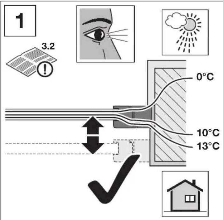
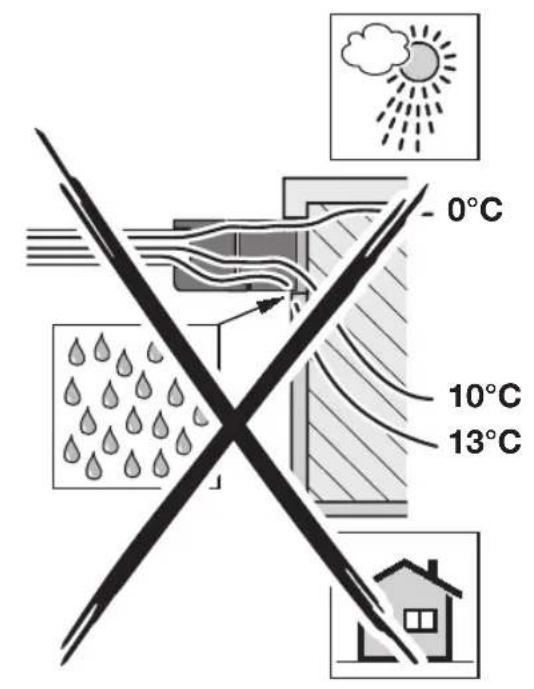
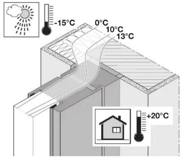
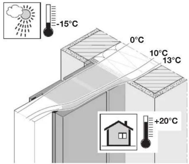
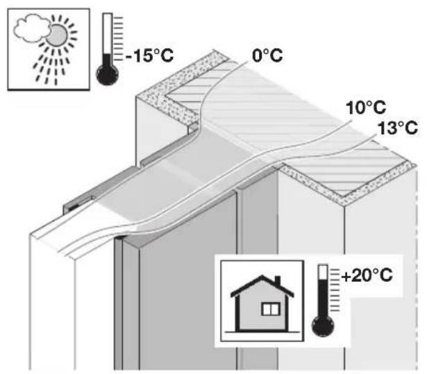
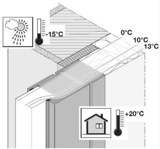
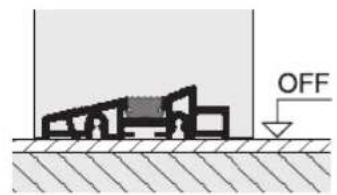
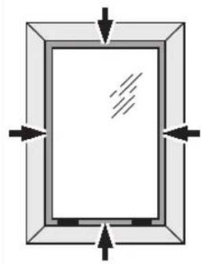
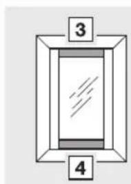
If possible, position the door so that it is within the insulation layer of the wall. With monolithic or single-shell brickwork, position the door as close as possible towards the building interior side. Observe the isothermal lines (see Figure 1).
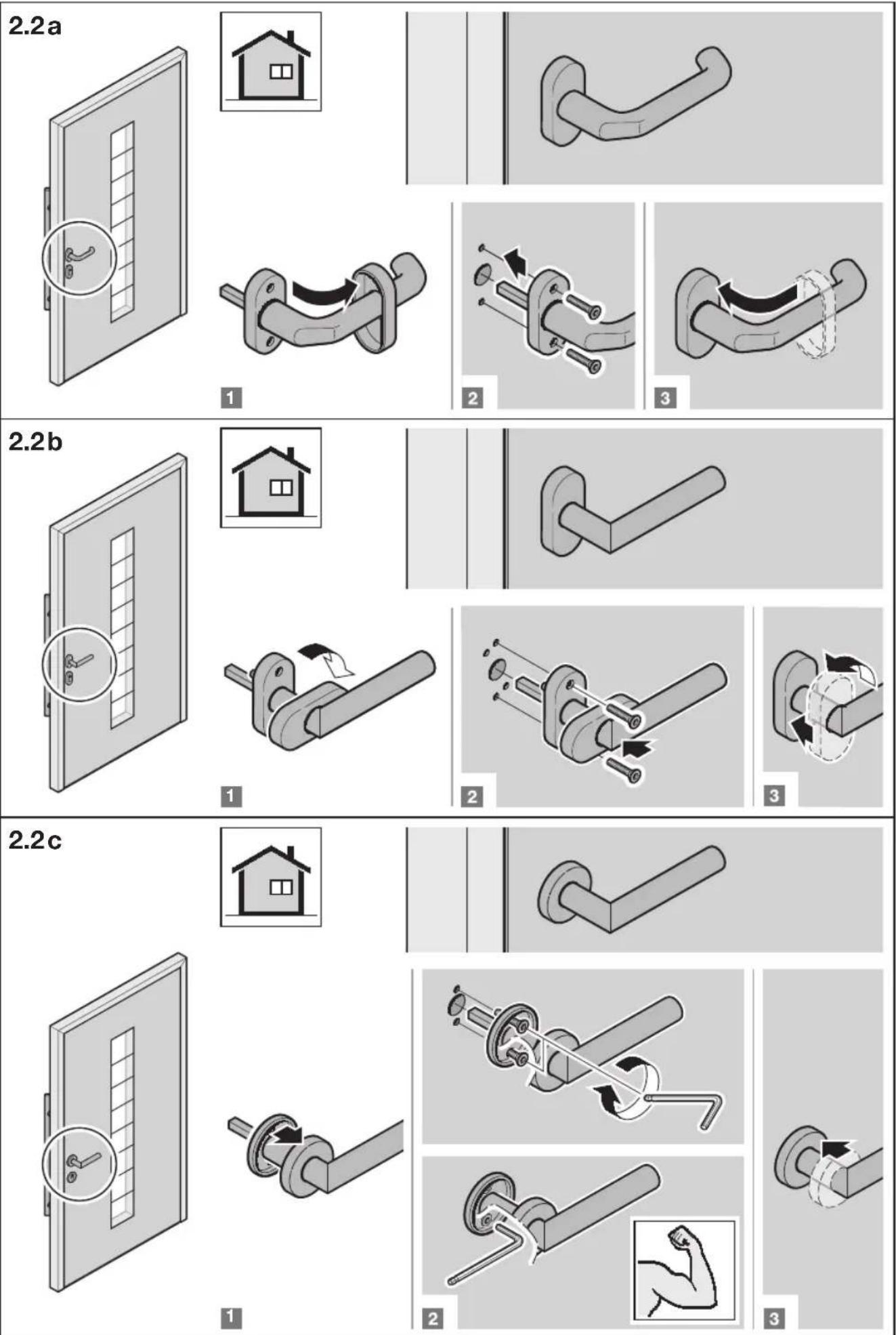
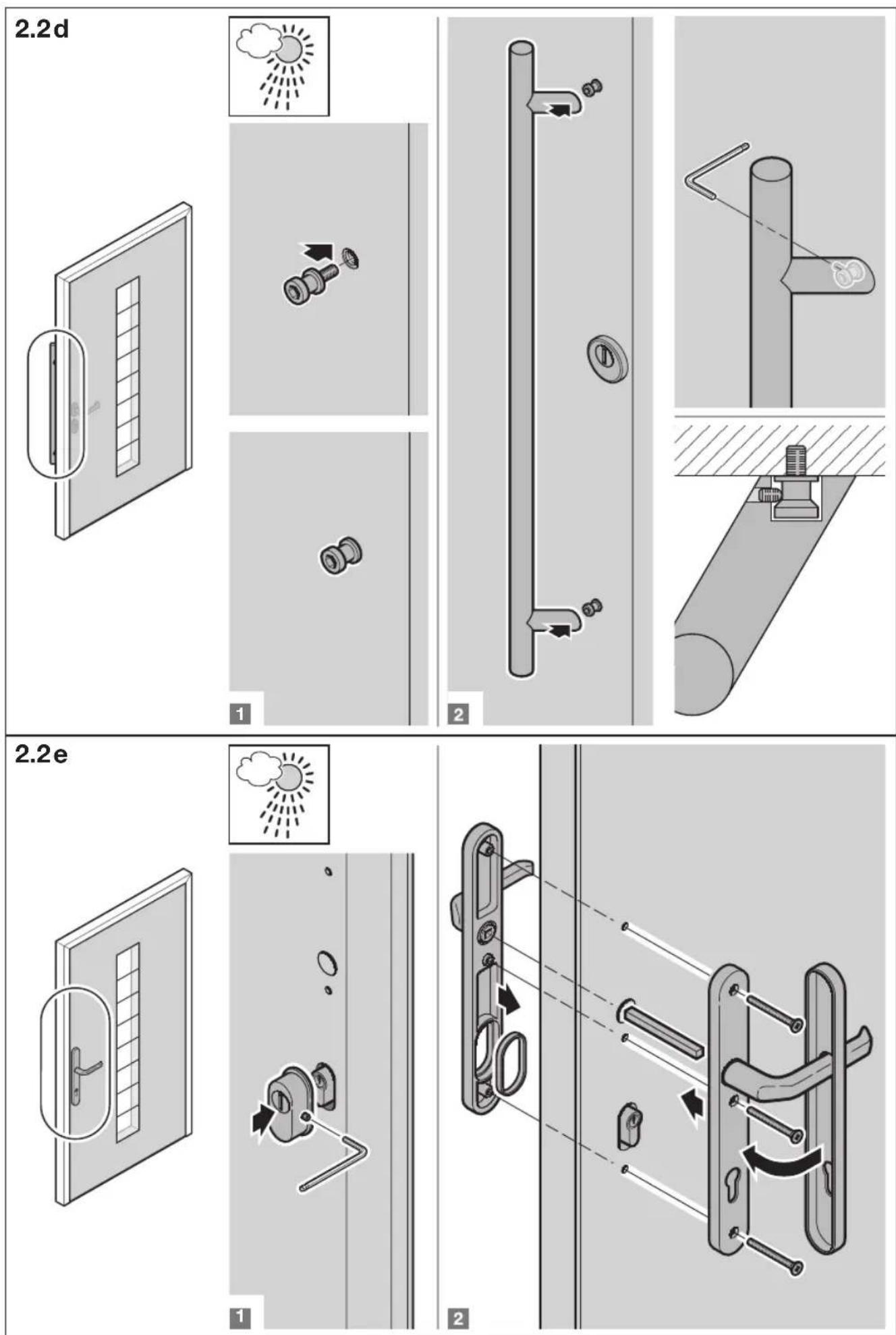
3.3 Fitting types
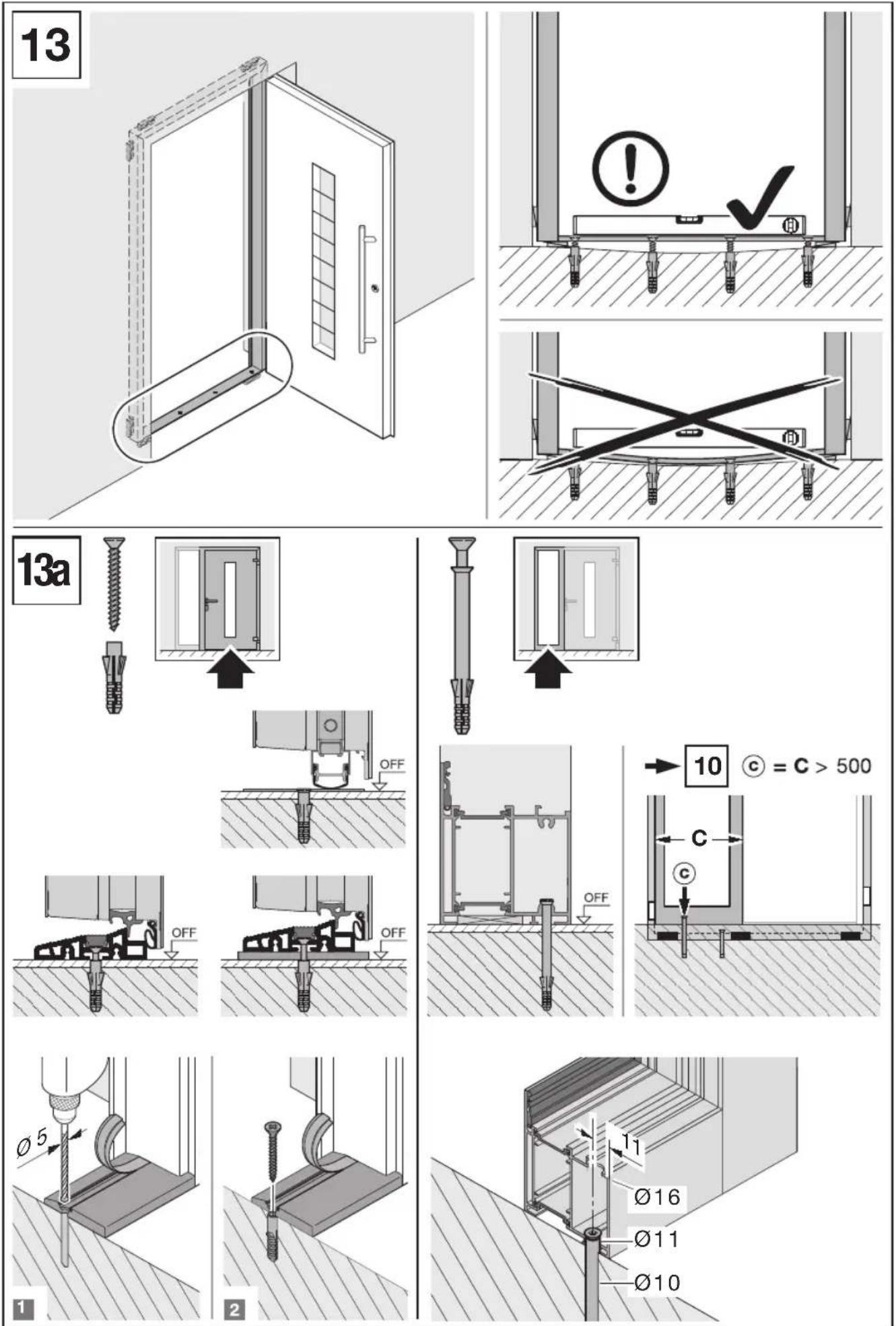
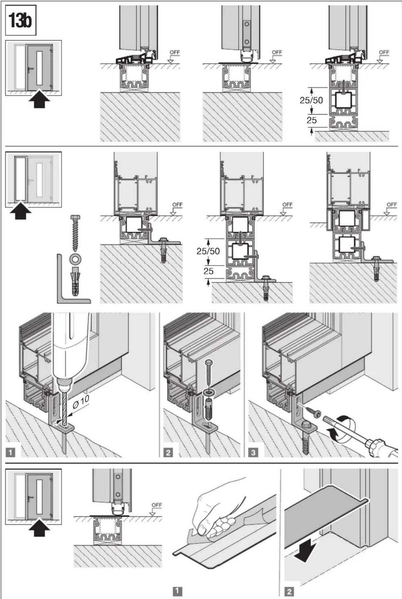
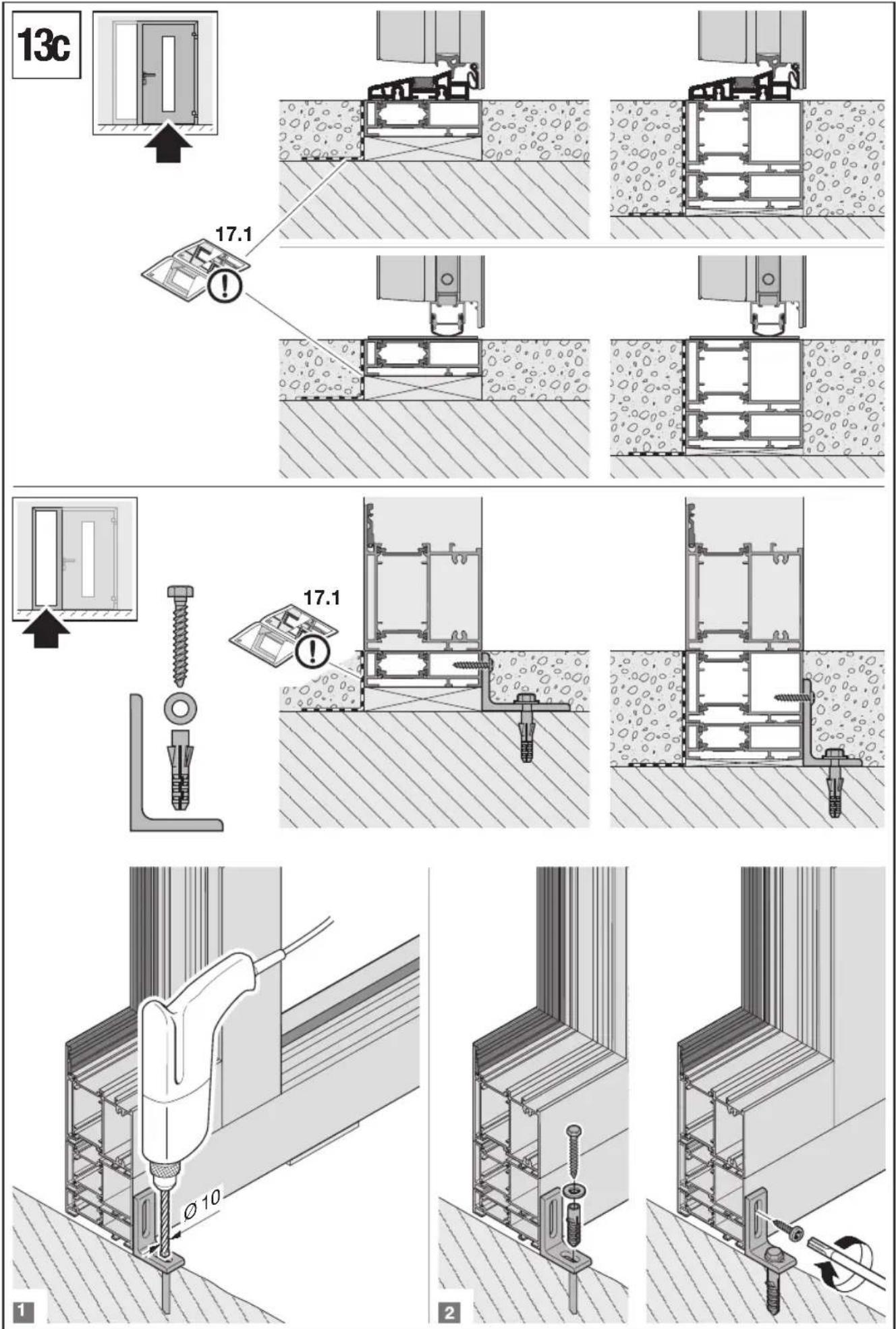
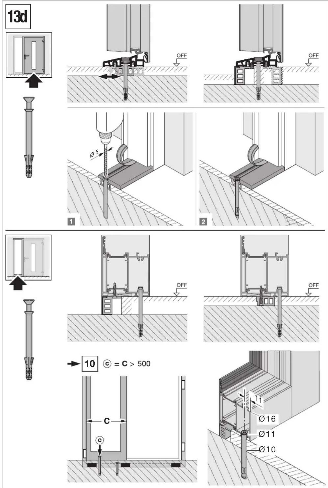
- Anchor fitting (see Figures 10-12)
Plug-and-screw fitting (see Figures 10-12)
- Frame screw fitting (see Figures 10-12)
NOTE:
Each fixing point must be back-blocked resistant to pressure.
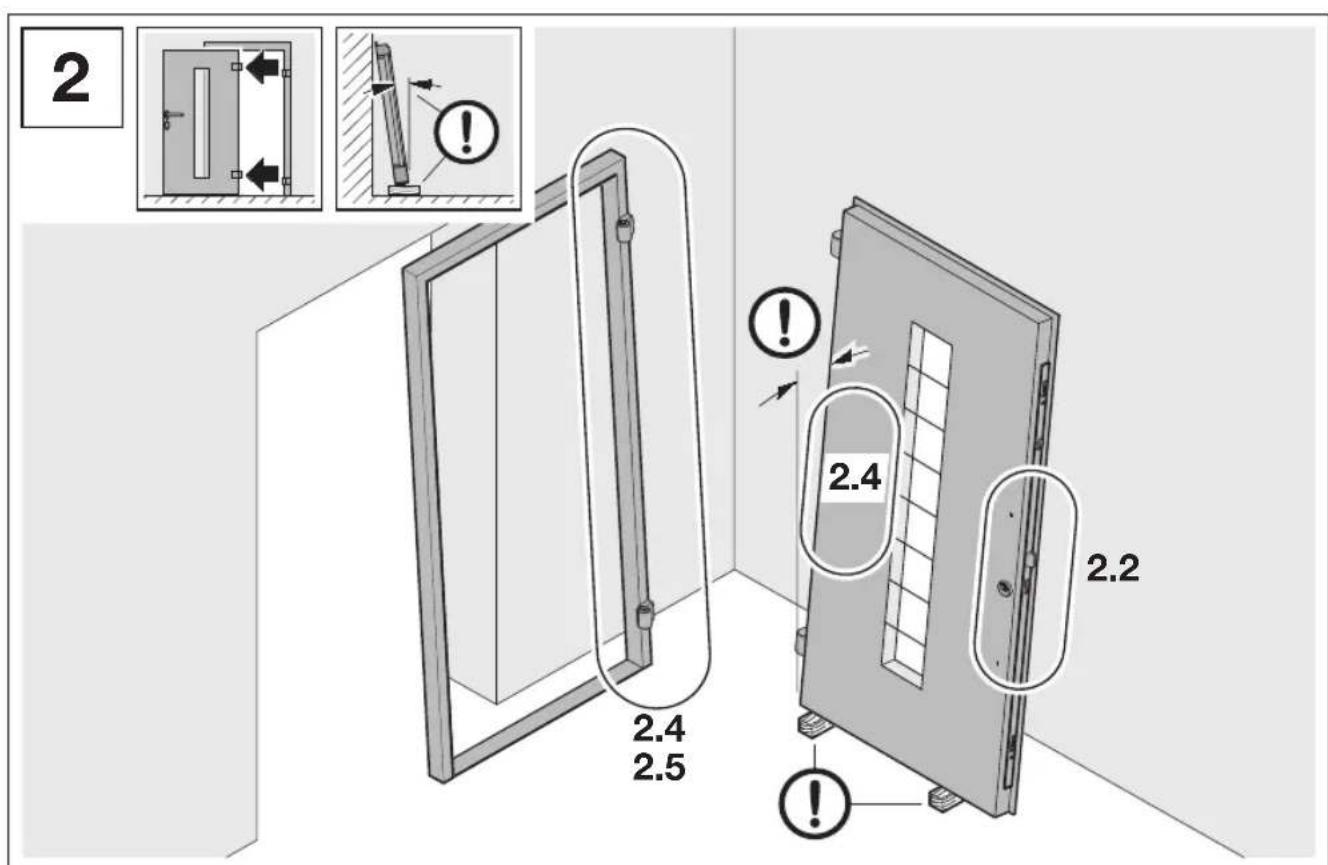
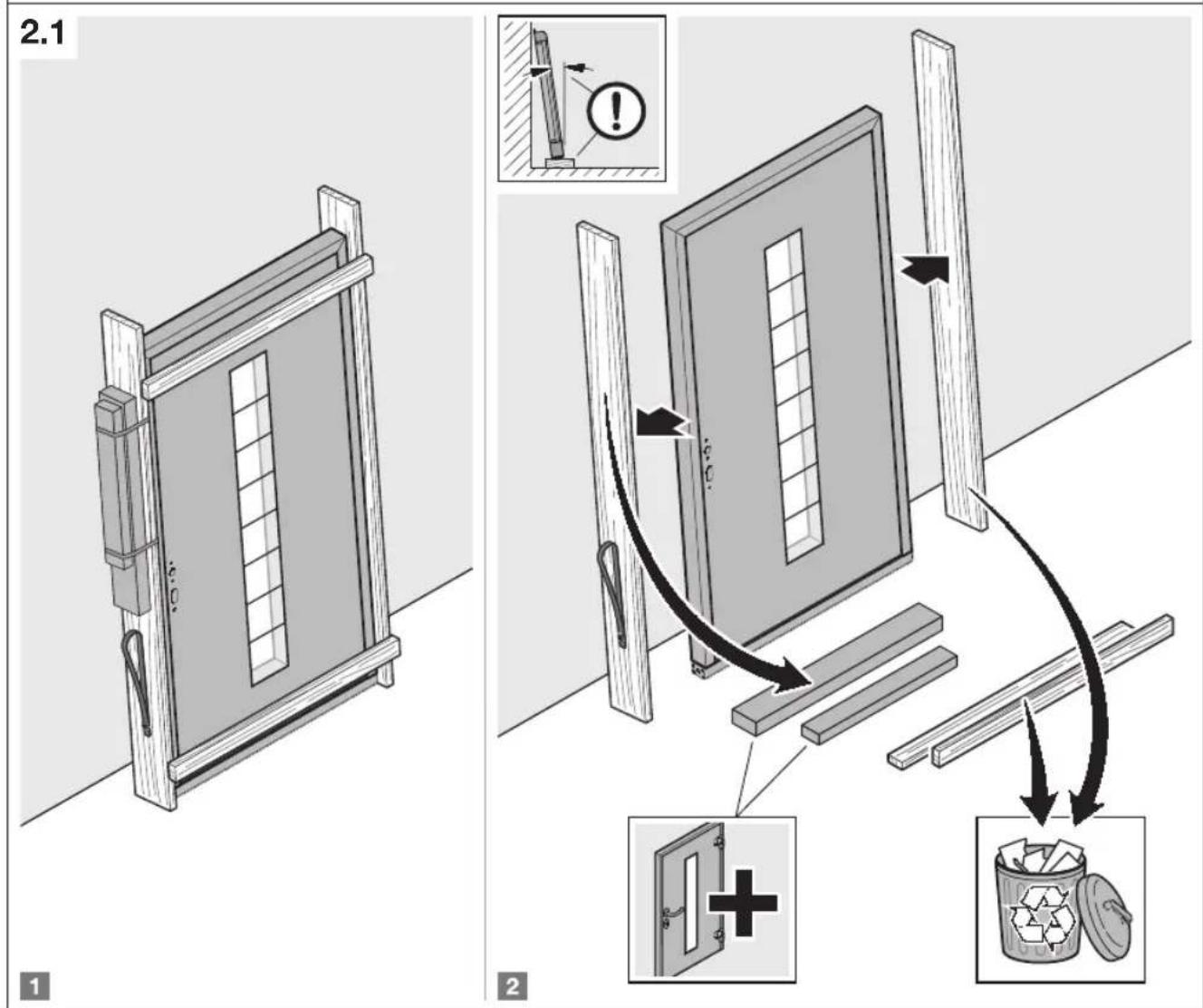
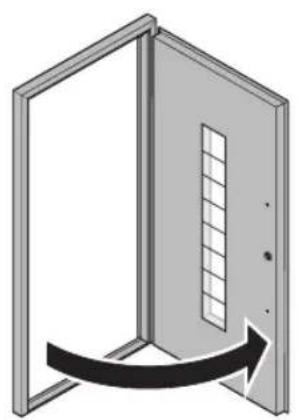
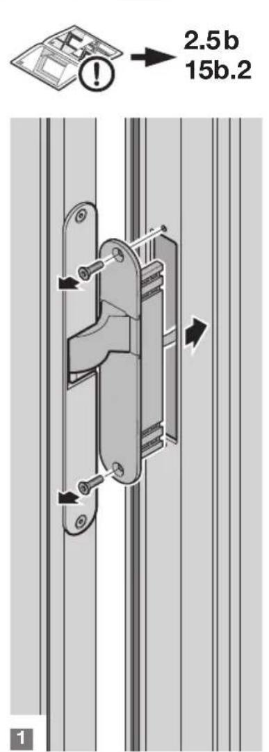
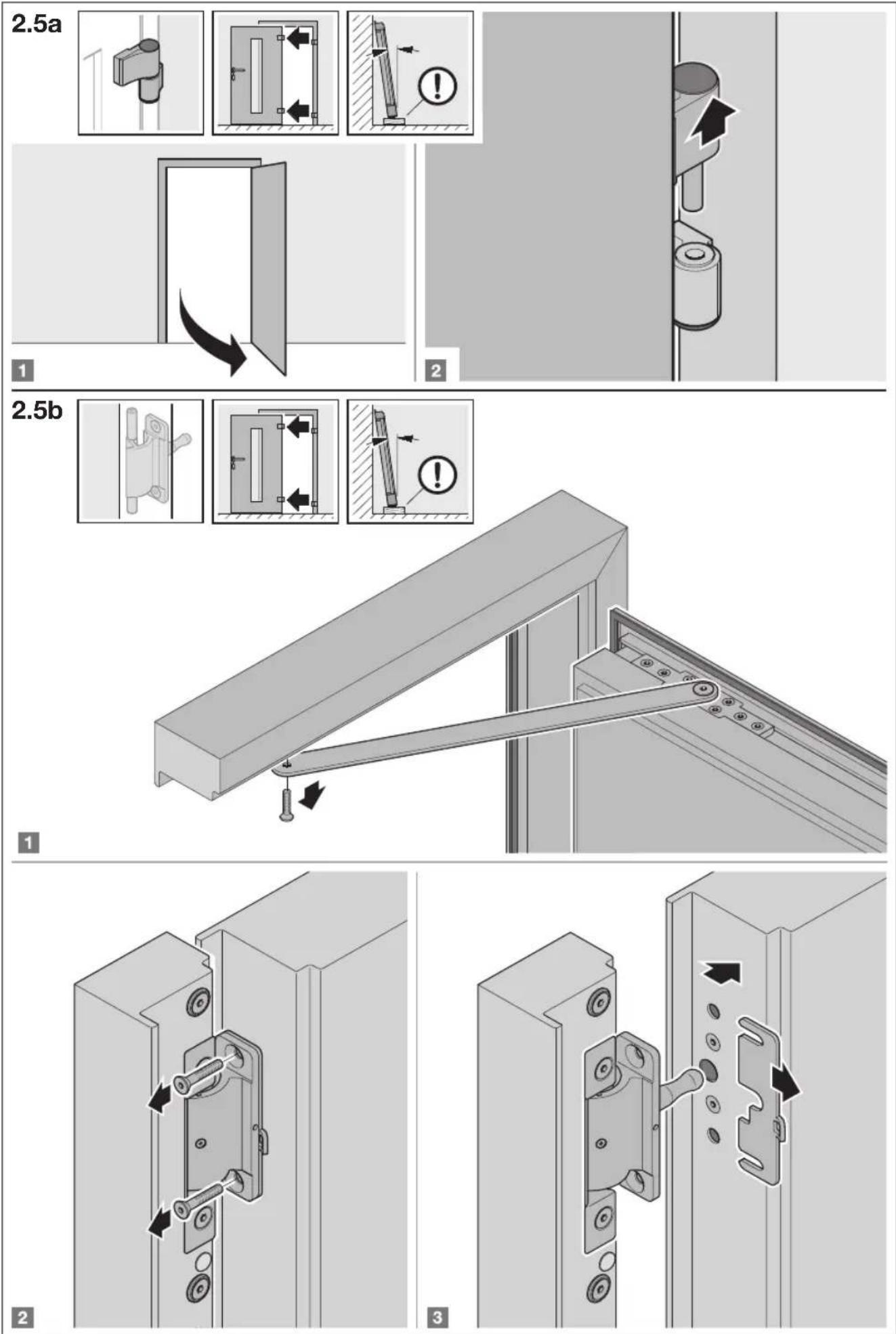
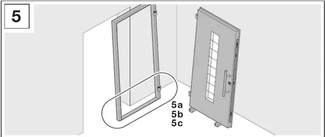
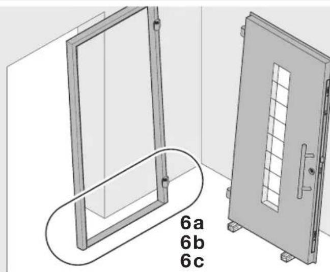
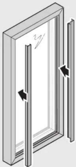
Unhinge the door leaf (see Figures 2.5/15a/15b).
ATTENTION
Impaired function
Non-compliance with the handling guidelines will impair the function of the entrance door.
With fixing and sealant material, follow the handling guidelines of the respective manufacturer.
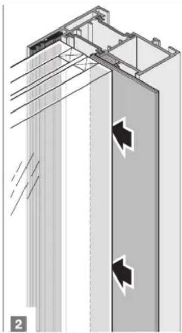
3.4 Connection to building structure
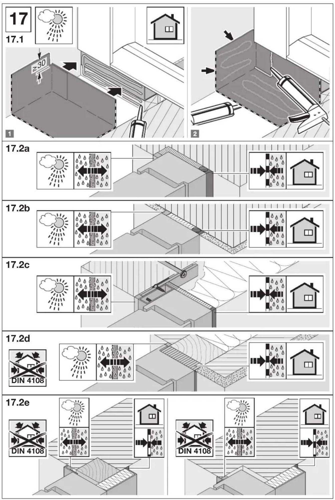
Proper fastening, load transfer and sealing of the connection joint to the building structure is a fundamental prerequisite for permanent usability of the door. It depends on the respective exterior wall system and fitting situation. Comply with the requirements of the current EnEV, the specifications of the RAL quality monitoring association for windows and doors e.V. and the manufacturer's processing guidelines.
| The following generally applies: | |
| Room side Air and | vapour diffusion-tight seal |
| Average range Thermal insulation unsusceptible to moisture |
| Exterior side Vapour diffusion-open wind and rain barrier |
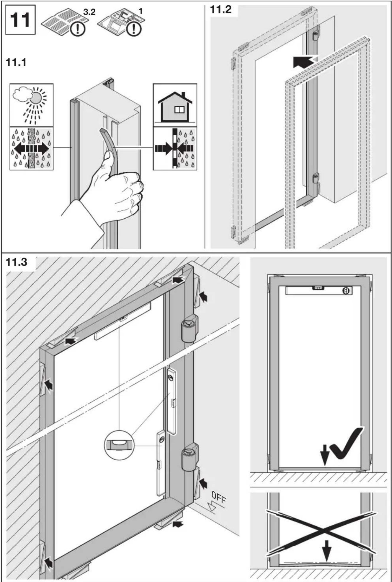
(see Figure 11.1/17).
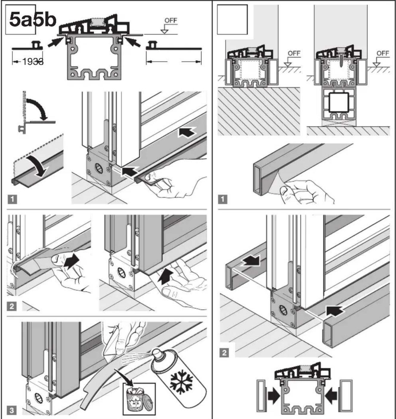
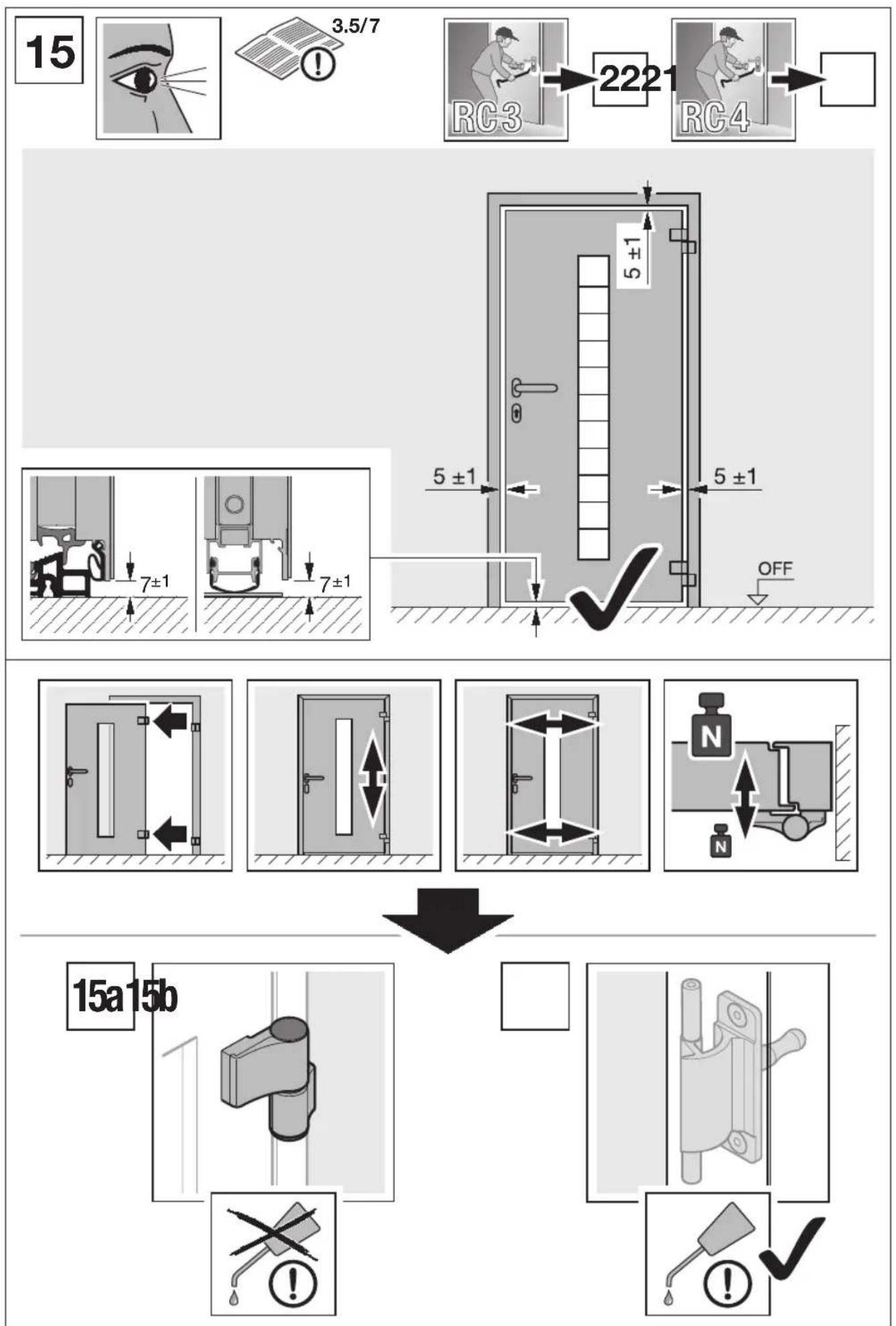
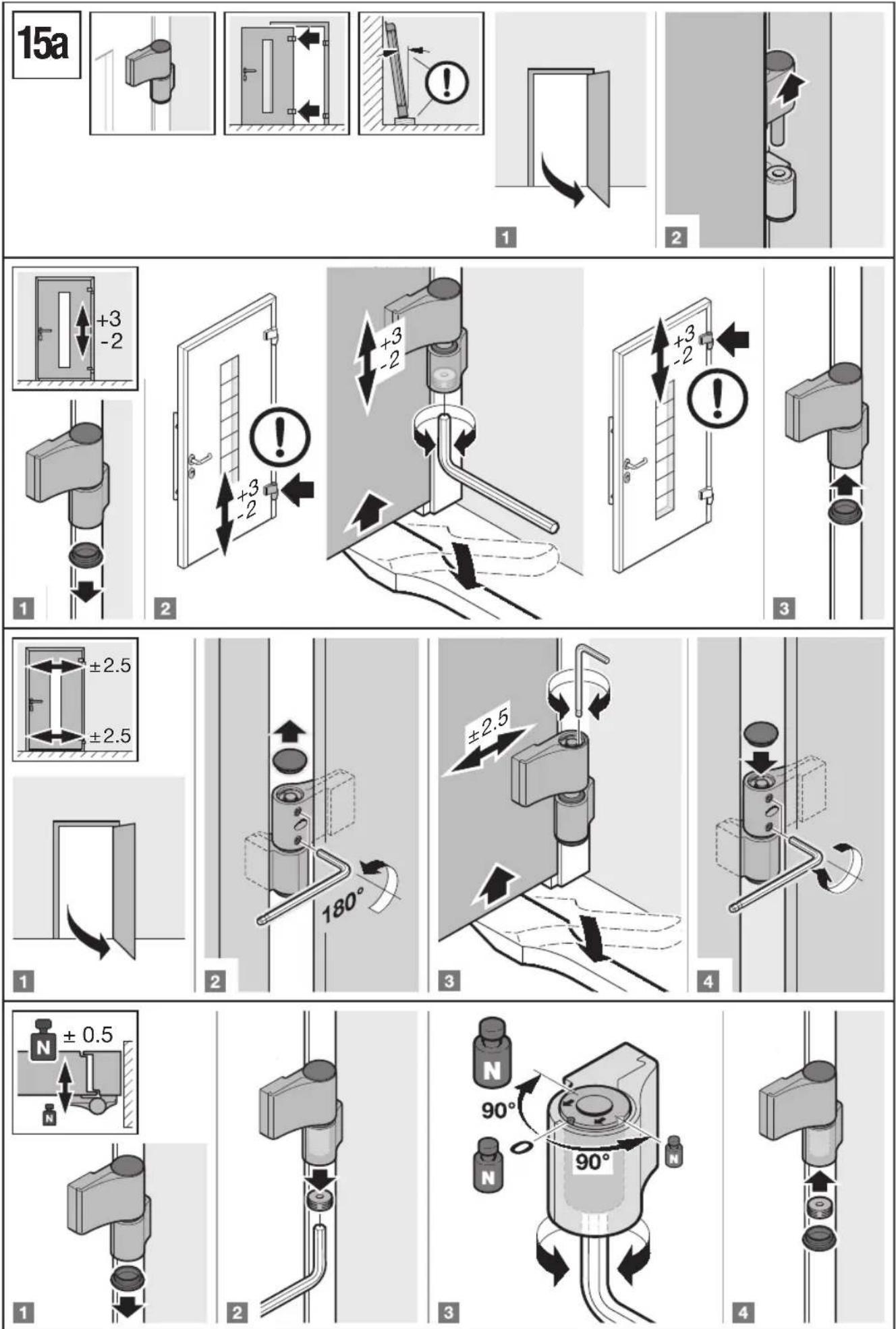
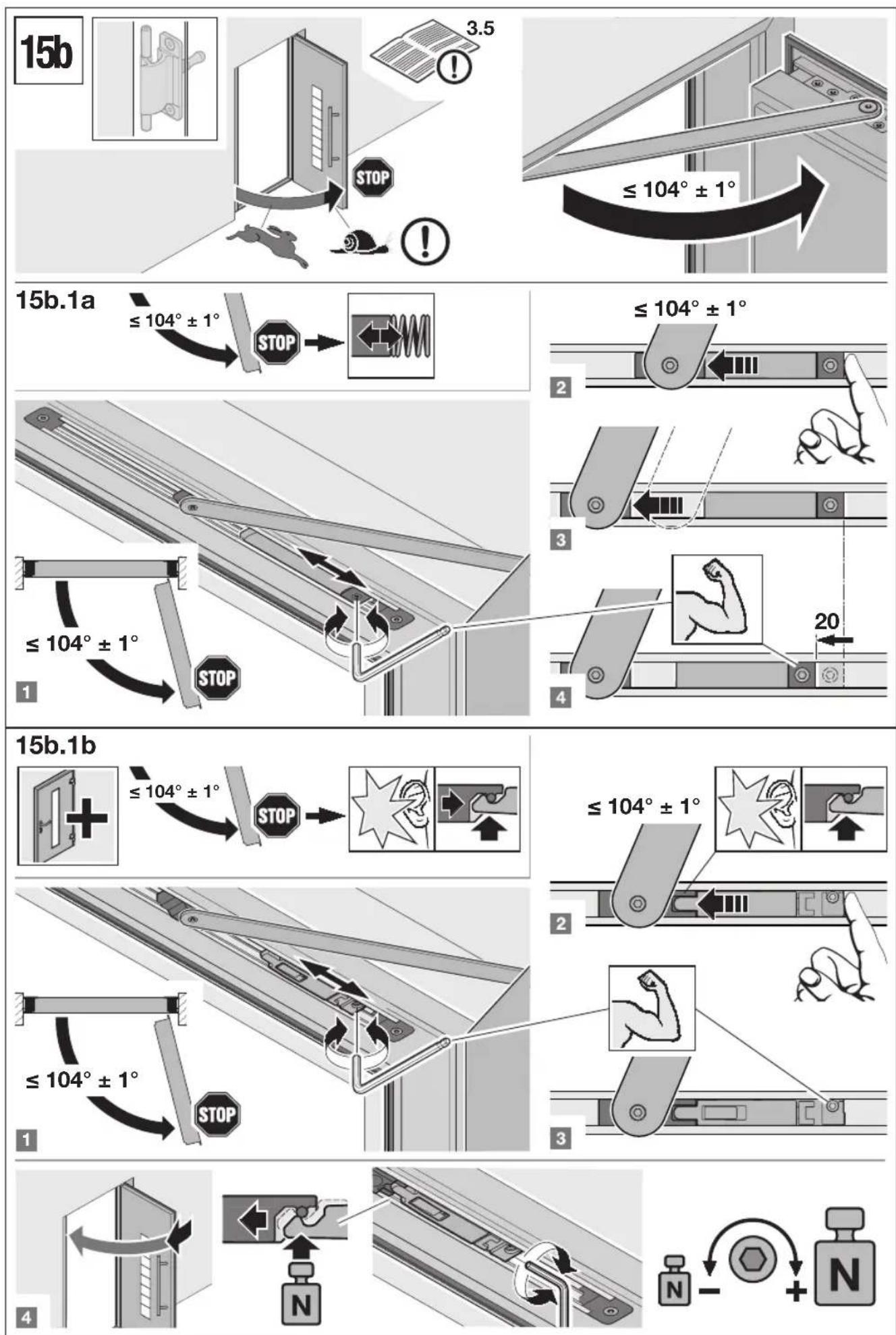
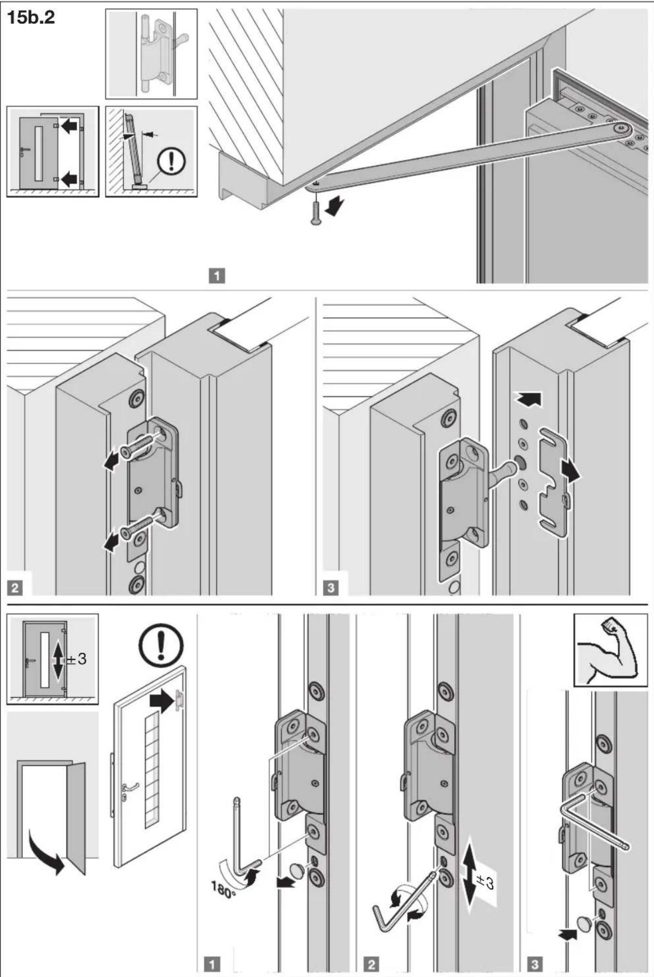
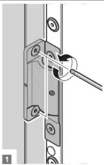
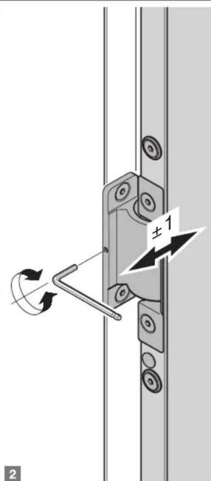
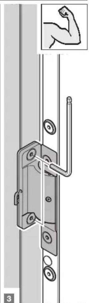
3.5 Adjusting the fitting
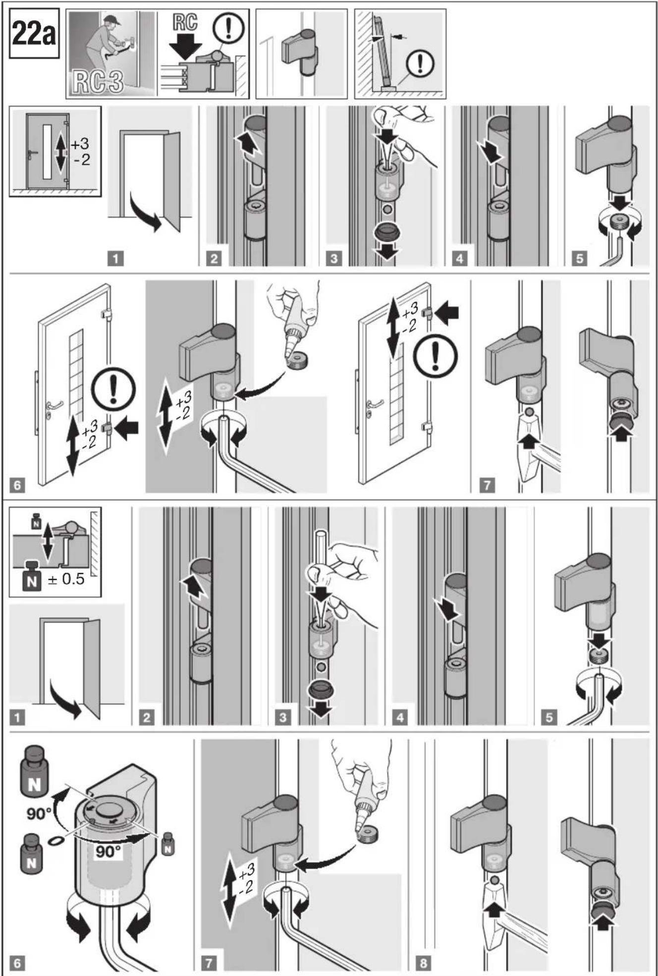
Horizontal and vertical door leaf adjustment, contact pressure adjustment (see Figures 15a-15b).
ATTENTION
The door opening angle must be limited to 105^ on site.
Note that for concealed hinges, the door opening angle must be limited to 105^ , as otherwise damage to the hinge or door frame can be expected.
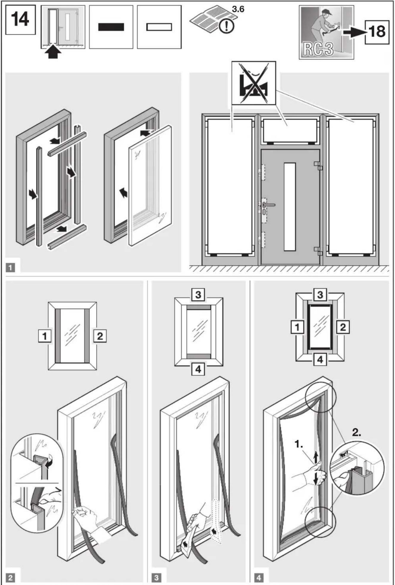
3.6 Glazing
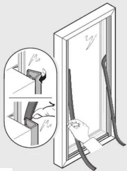
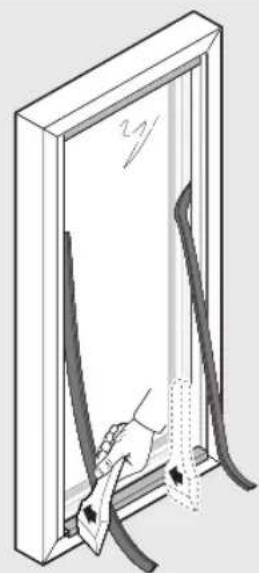
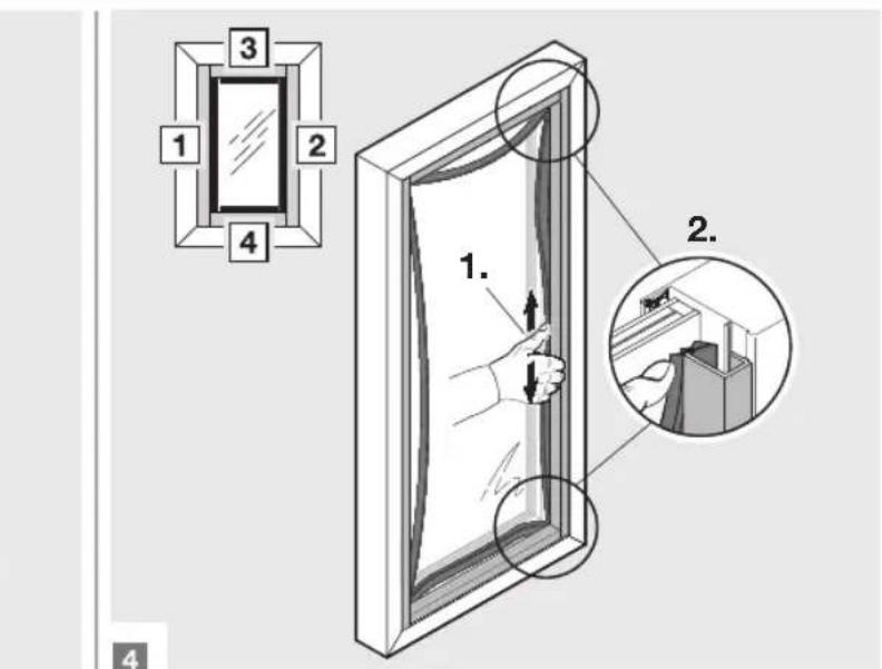
- Insertion and replacement of the glass panes or infills (see Figure 14).
- Blocking suggestions (see Figure 14)
- Secure blocking against falling (e.g. with PatTex adhesive).
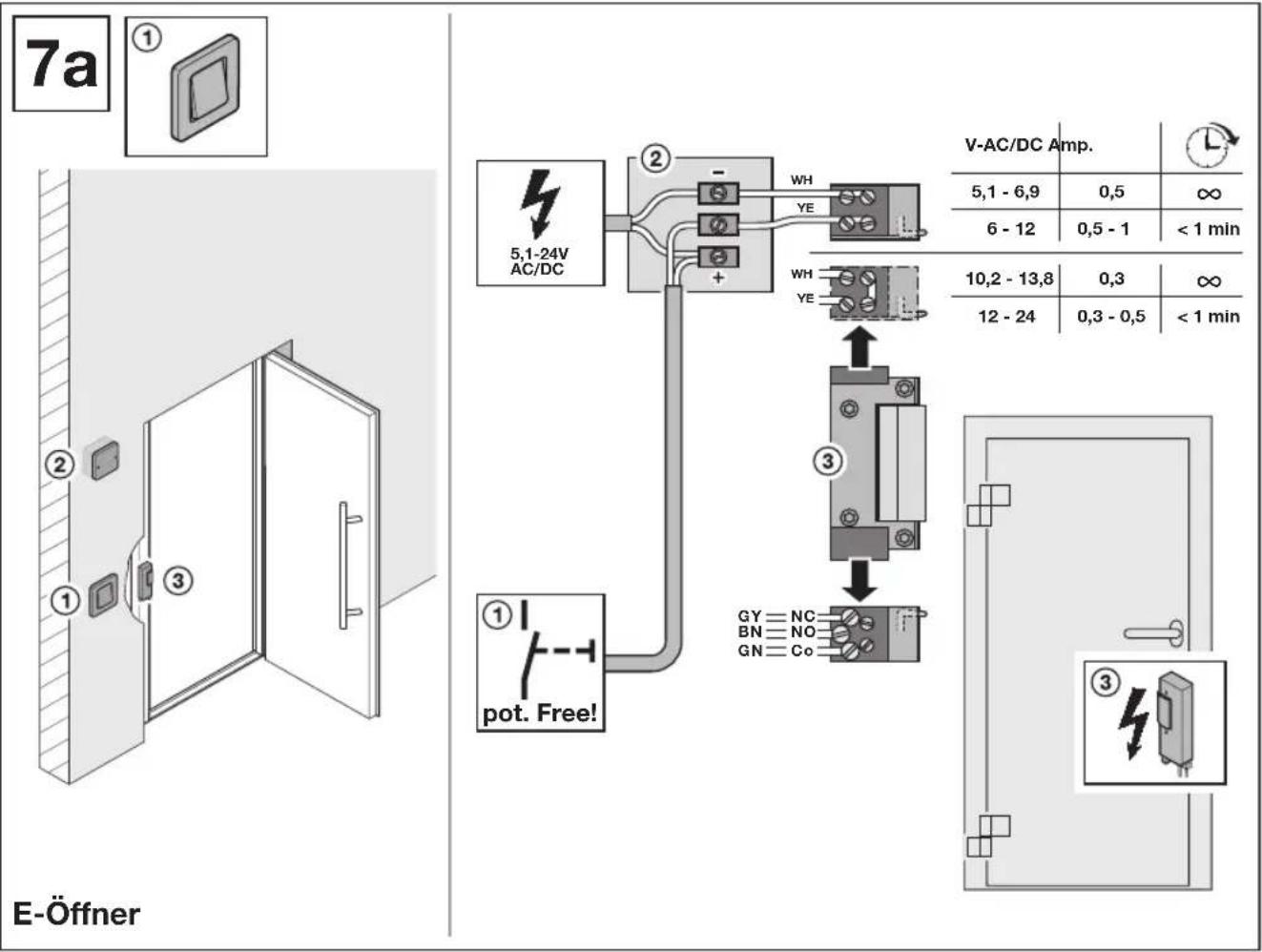
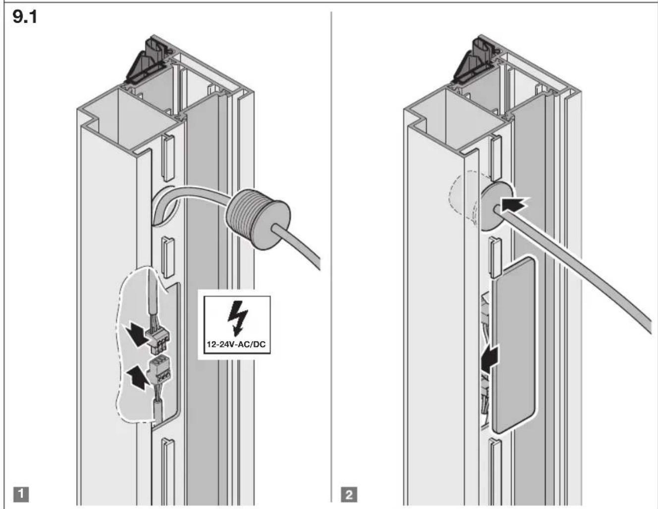
3.7 Electrical connections
DANGER
Mains voltage!
Contact with the mains voltage presents the danger of a deadly electric shock. For that reason, observe the following warnings under all circumstances:
Electrical connections may only be performed by a qualified electrician!
The on - site electrical installation must conform to the applicable protective regulations!
Qualified electricians must ensure compliance with the national directives for the operation of electrical devices!
Depending on the length of the power supply cable, it must have at least the following cross-section:
| 10 m 0,50 mm2 | 75 m 1,50 mm2 |
| 40 m 0,75 mm2 | 125 m 2,50 mm2 |
| 50 m 1,00 mm2 | |
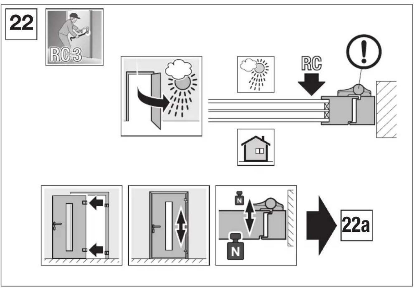
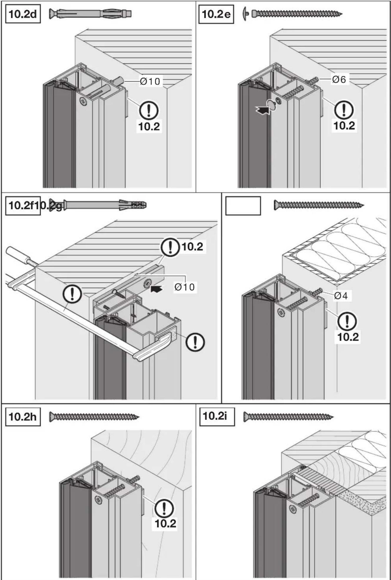
3.8 Fitting break-in-resistant door sets
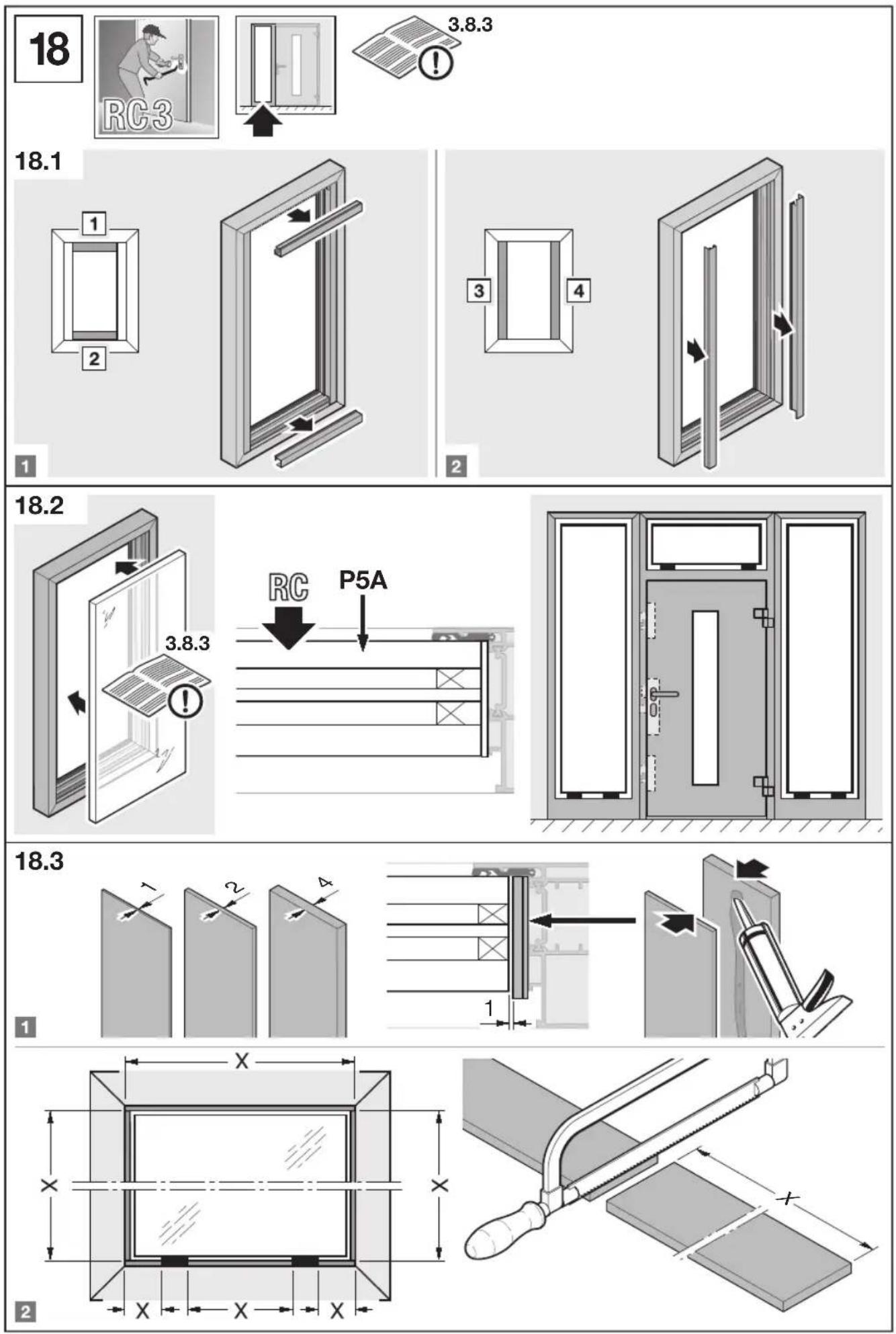
The fitting instructions in this section give additional tips on fitting break-in-resistant door sets with resistance classes RC 3 acc. to DIN EN 1627: 2011 (see Figures 18-22).
Only by a professional fitting in accordance with these instructions will the door sets be equipped with break-in-resistant features.
3.8.1 Permissible walls
The required break-in-resistance can only be obtained if the adjacent walls meet the requirements according to Tab. 1 - Tab. 3.
3.8.2 Permissible wall connections
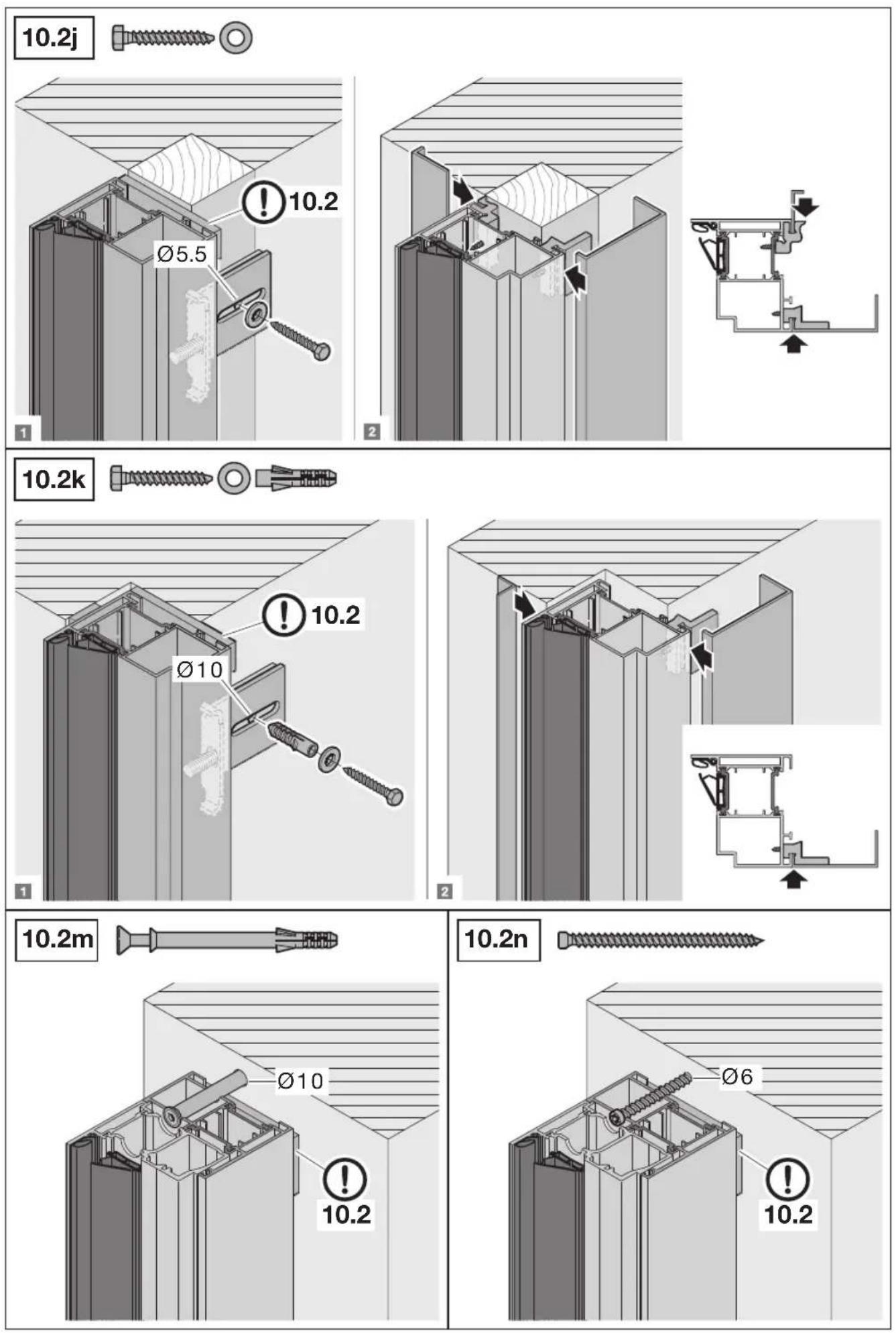
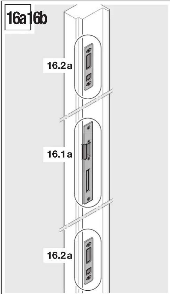
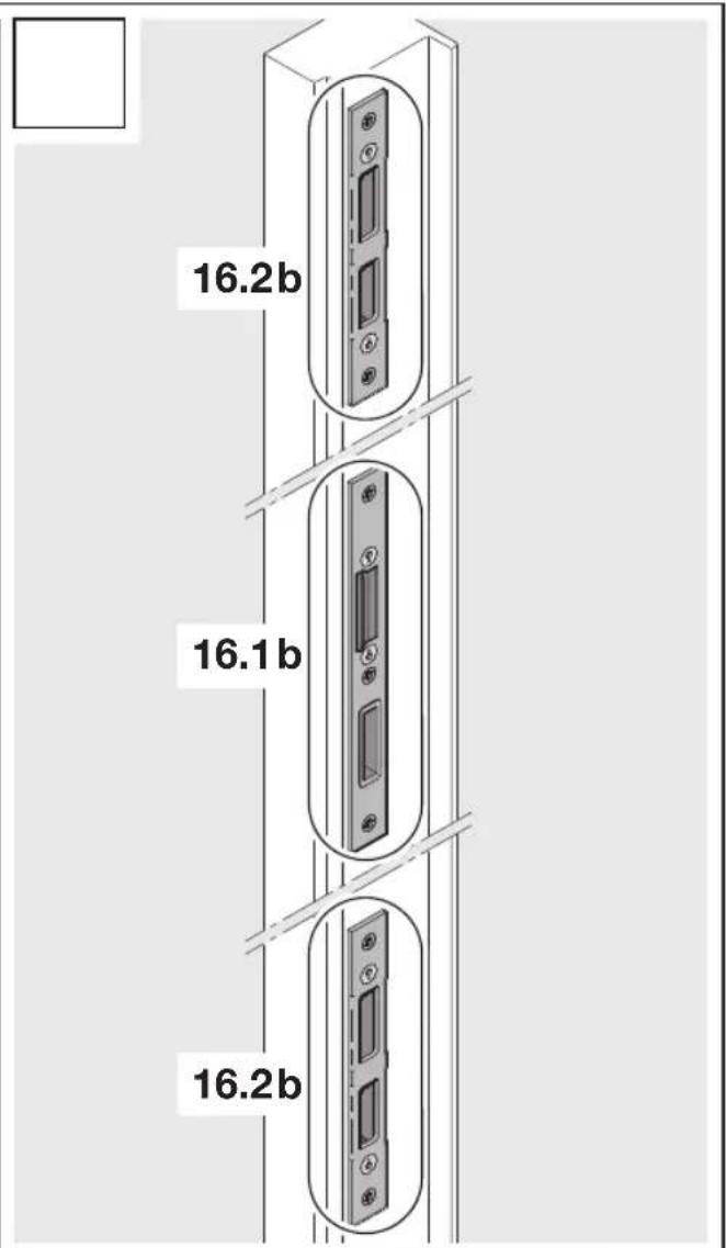
The wall connections defined in Image 10.2a-10.2n are permissible. Expert fitting must be verified with a fitting certificate.
3.8.3 Safety relevant components
The required break - in - resistance can only be obtained if the used infills meet the following requirements.
Minimum requirement for the side element, transom light infills:
| Resistance class RC 3 | |
| Glazing resistance class according to EN 356 | P5 A |
| Placement of the safety pane Attack side | |
| Panel with or without glass Aluminium panel |
The exchange of safety-relevant components (e.g. fittings, locks and infills) can lead to a loss of door set resistance.
Tab. 1: Classification of the resistance classes of break-in-resistant components for solid walls
| Resistance class of the component acc. to DIN EN 1627 | Surrounding walls |
| In brickwork according to DIN 1053-1 | Reinforced concrete walls acc. to DIN 1045 |
| Wall thickness (unplastered) | Compression strength class of the bricks (DFK) | Apparent density class of the bricks (RDK) | Mortar group [min.] | Nominal thickness [min.] | Strength class [min.] |
| RC 3 ≥ 115 mm | m | ≥ 12 | - | MG II/DM ≥ 140 m | ≥ 120 mm | B 15 |
| RC 4 ≥ 240 mm | m | m |
Tab. 2: Classification of the resistance classes of break-in-resistant components for gas concrete walls
| Gas concrete wall |
| Resistance class | Compression strength class of the bricks | Nominal thickness Version | |
| RC 3 ≥ 4 ≥ 240 mm | Bonded | | |
Tab. 3: Classification of the resistance classes of break-in-resistant components for timber panel walls
| Resistance class Suitable | wall construction |
| RC 3 | | Tongue + groove timber cladding 19 × 120 mm, batten 40 × 60 mm, SB.W 60 mm, timber post 60 × 140, MF 140 mm, PE plastic film, OSB 15.0 mm, GKB 12.5 mm |
| Plaster with fabric, SB W 40 mm, DWD 15.0 mm, timber post 60 × 140, MF 140 mm, kraft paper, BFU 15.0 mm, GKB 12.5 mm |
| Plaster with fabric, approx. 4 mm, PS 30 mm, FP 13 mm V100E1, timber post 60 × 140, MF 140 mm, PE plastic film 0.2 mm, FP 13 mm V20E1, batten 40 × 60 mm, insulation MF 40 mm, BFU 15.0 mm, GKB 9.5 mm |
| RC 4 | | Plaster with fabric, approx. 4 mm, SB.W 60 mm, DWD 15 mm, timber post 60 × 160 mm, SB.W 160 mm, sodium kraft paper, OSB 22 mm, BFU 15 mm, GKB 12,5 mm |
| Plaster with fabric, approx. 4 mm, SB.W 60 mm, DWD 15 mm, timber post 60 × 160 mm, mineral fibre 160 mm, sodium kraft paper, FP 13 mm V20, sheet metal 0,75 mm, FP 13 mm V20, GKB 9,5 mm |
Prefabricated and timber partition walls with respective resistance class suitability certification from the manufacturer. Deviating walls possible in accordance with EN 1627.
Minimum requirements for the fittings:
| Resistance class RC 3 RC 4 | | |
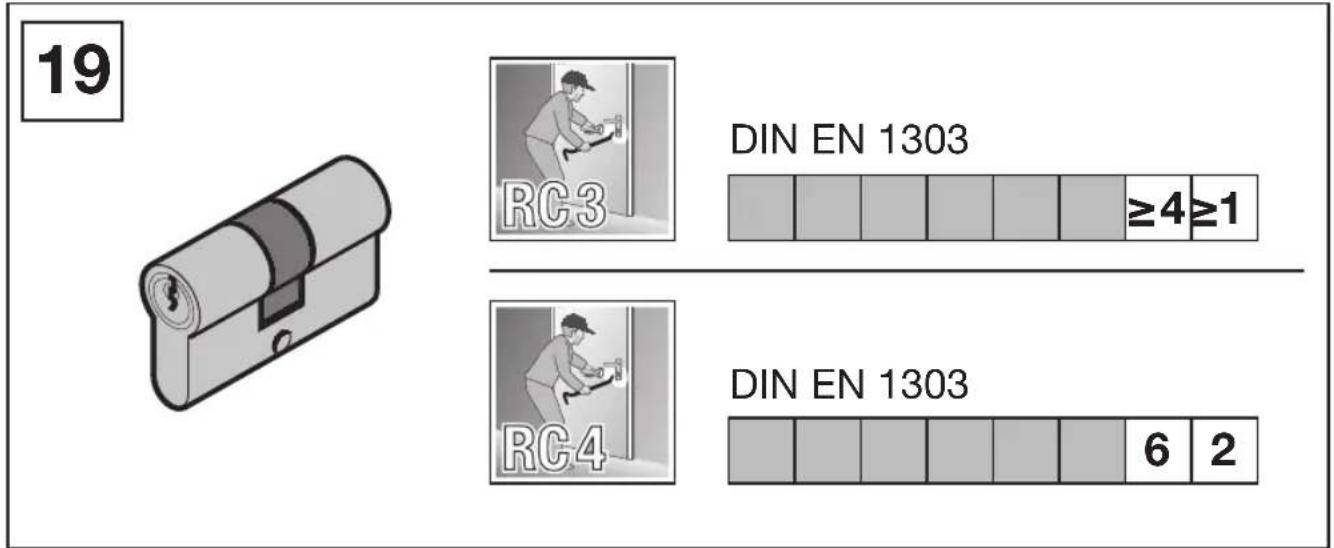
| EN 1303 (see Figure 19) | | |
| Locking cylinder (position 7) | 4 | 6 |
| Locking cylinder (position 8) | 1 | 2 |
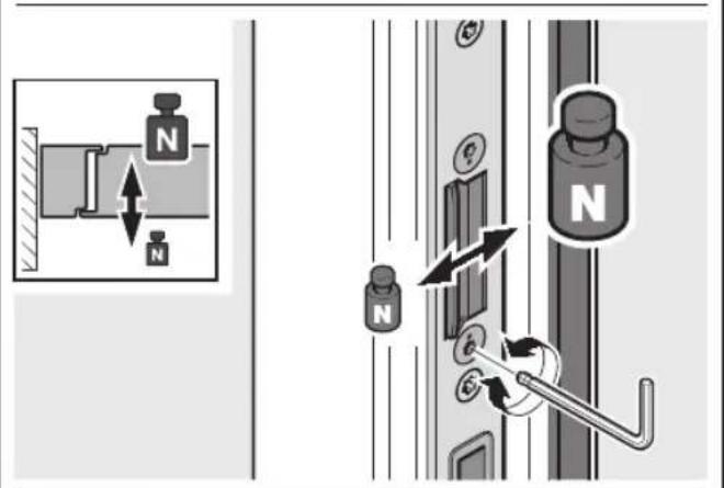
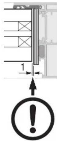
Be sure to observe the following fitting instructions:
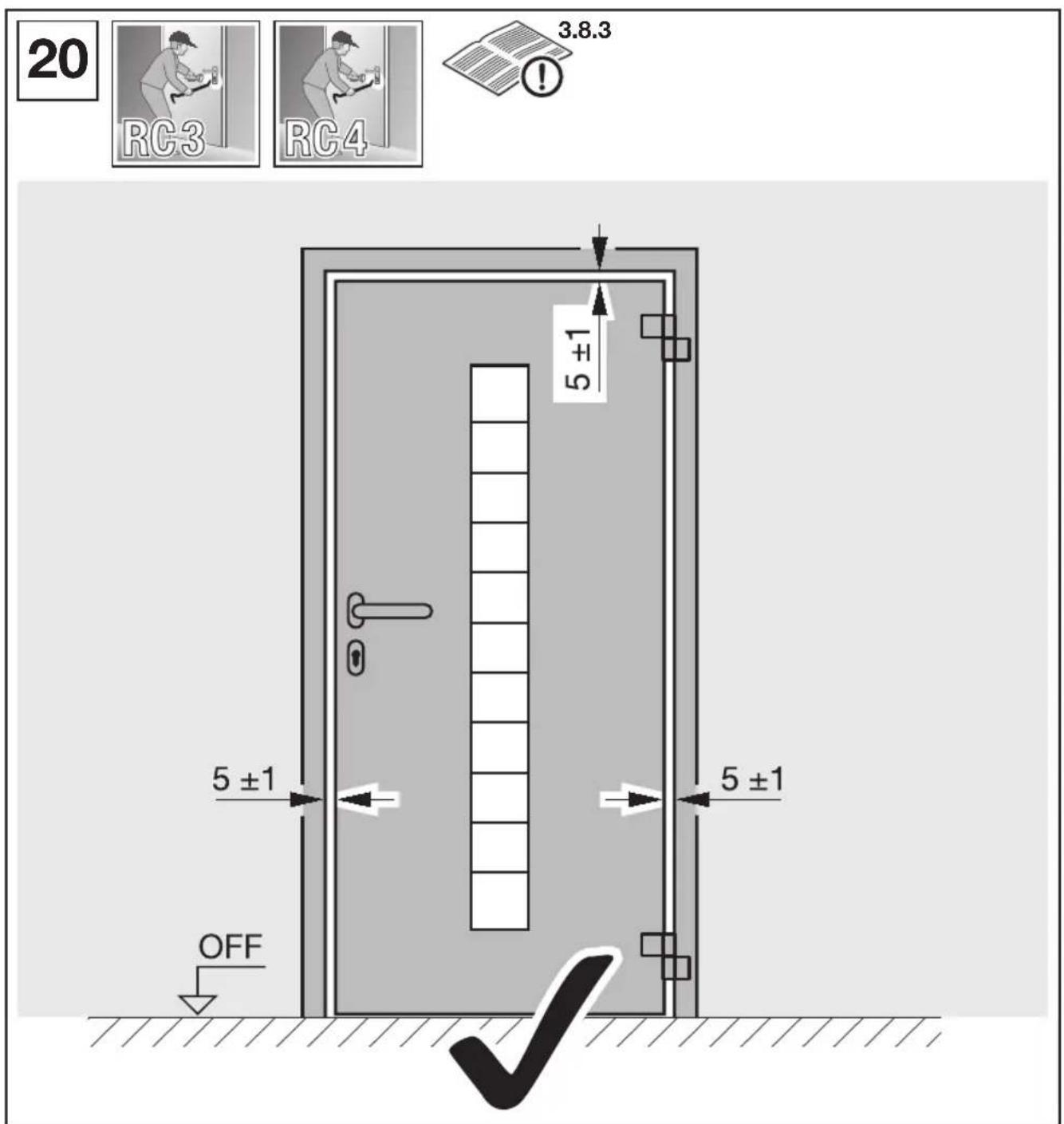
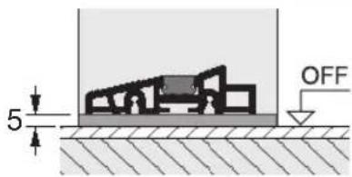
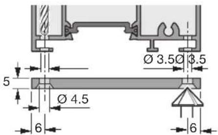
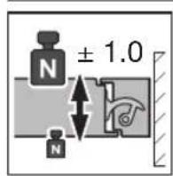
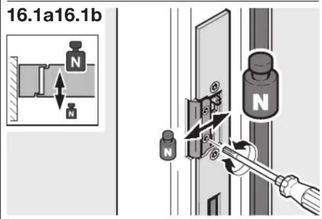
The visible gap of 5± 1 mm between frame and leaf must be observed (see Figure 20) so that the lock bolts fully extend into the lock plate openings.
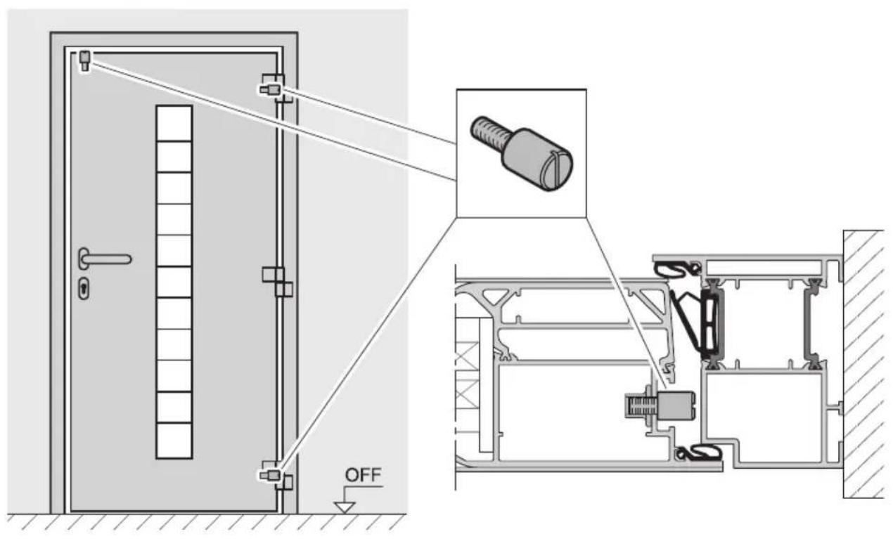
3.8.4 Additional instructions for fitting
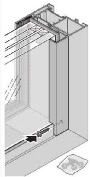
Install the frames vertically and properly aligned (see Figure 11).
In the areas described below, back-fill the spaces between frame and walls with a rot-free material to withstand pressure:
— Hinges
Infill
- Locking
Fixing points
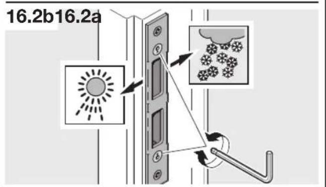
- On the upper and lower corners
By taking suitable precautions (e.g. silicone), make sure that the pressure-resistant back-packing is not able to shift (see Figure 10.2).
3.8.5 Instructions for the user
3.8.6 Guarantee
To ensure the performance criterion "break-in resistance in accordance with DIN EN 1627" with classification RC 3 the fitting company must confirm expert fitting in accordance with these instructions by means of the document "Fitting certificate for break-in-resistant doors" provided with the order confirmation and return this document filled out to the manufacturer.
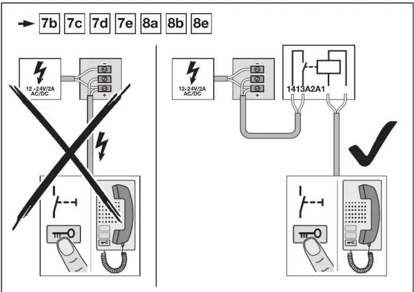
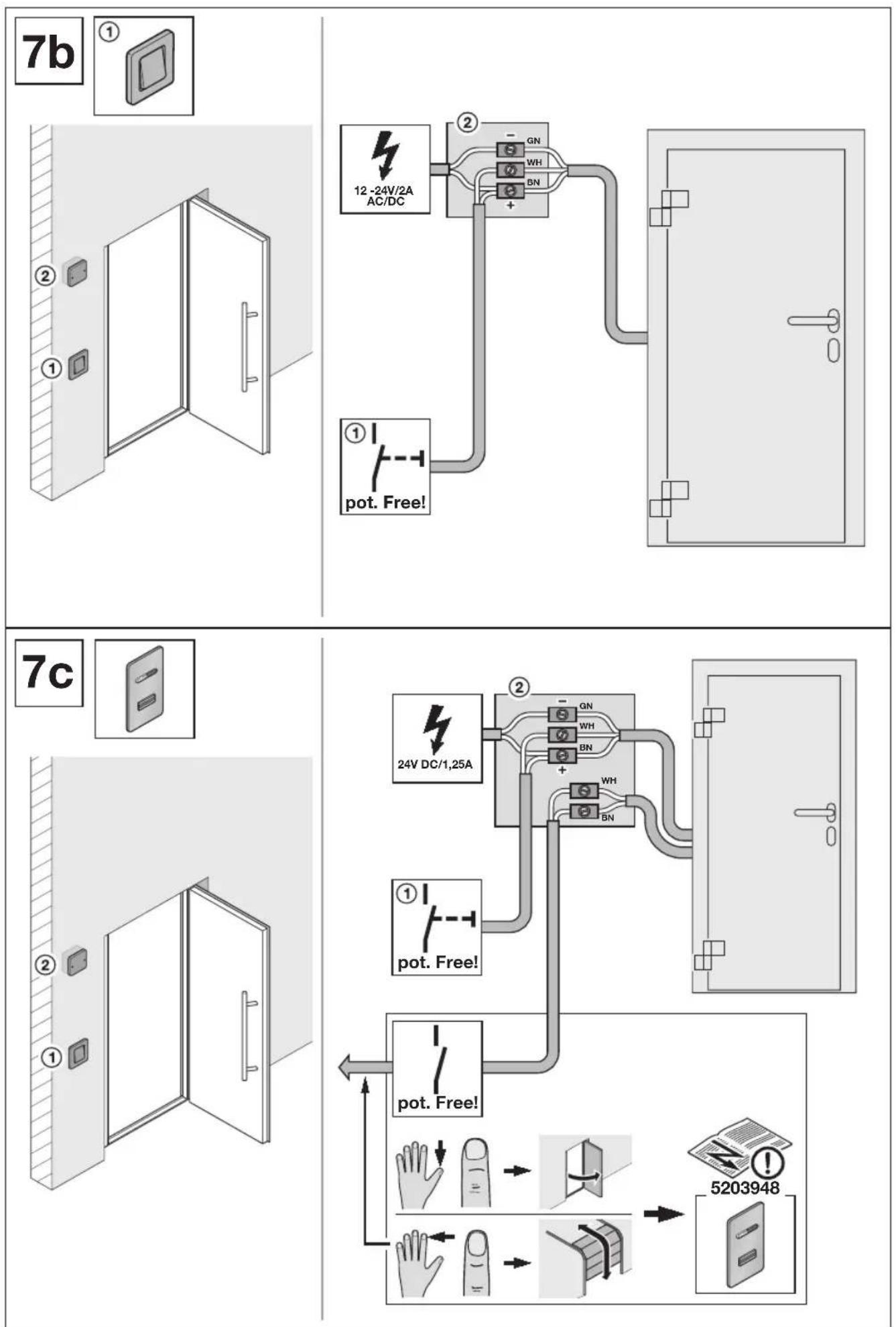
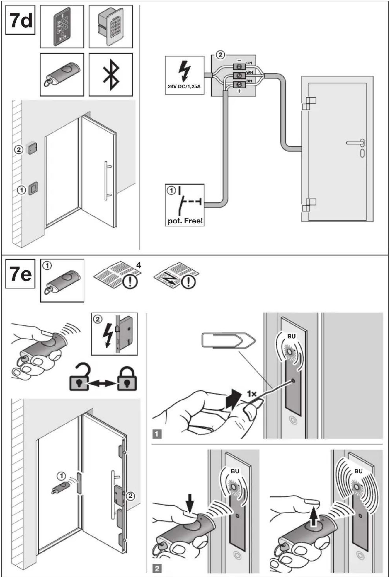
4 Description of S5 Smart,Comfort,Code, Scan
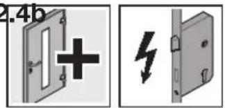
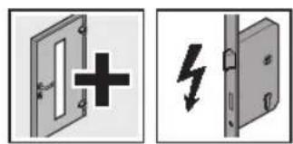
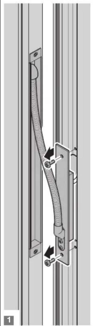
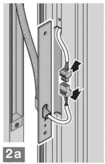
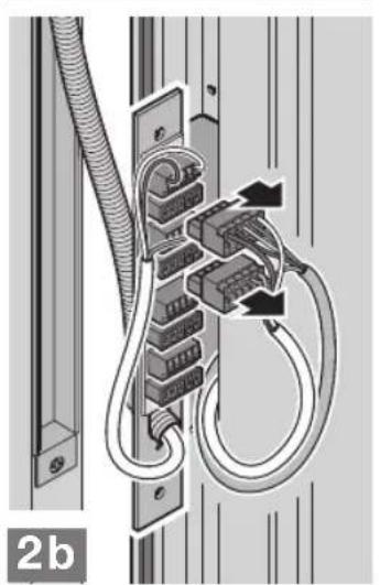
Volt-free control of the locks (see Image 7b/7c/7d)
If the locks are to be controlled via intercom/buhtons to which voltage is applied at the output, this cable must be switched to volt-free by fitting a coupling relay. Coupling relay for standard cases (12 V AC) in accessories.
The factory code must be changed for the initial start-up of the finger scanner! For this, see the included operating instructions.
4.1 LED display
Blue (BU)
| Condition Function | |
| Illuminated briefly A valid radio | code was discovered for channel 1 |
| Illuminated long once A valid radio | radio code is discovered that has been stored on both channels |
| Flashes slowly Receiver is in the | learn mode for channel 1 |
| Flashes quickly after slow flashing | A valid radio code was discovered during the learning |
| Flashes slowly for 5 seconds | Device reset is being implemented or completed |
| Flashes quickly for 2 seconds |
| Off Operation mode | |
Programming button P (P button)
4.2 Teaching in a radio code
To activate / switch a channel:
Press the P button once to activate channel 1.
To abort the learn mode:
Press the P button 3 times, or wait for the timeout.
Timeout
If no valid radio code is recognised within 25 seconds, the receiver automatically returns to the operation mode.
4.3 Teaching in a radio code
- Press the P button to activate the desired channel. - The blue LED will flash slowly for channel 1.
- Put the hand transmitter, whose radio code is to be inherited, into the Inheriting/Transmitting mode. If a valid radio code is recognised, the LED flashes quickly in blue then goes out. The receiver is in the operation mode.
4.4 Operation
In the operation mode, the receiver signals the recognition of a valid radio code by illuminating the blue LED.
NOTE:
If the radio code for the taught-in hand transmitter was copied from another hand transmitter, the hand transmitter button must be pressed a second time during initial start-up.
A valid radio code
channel 1 is discovered = The LED is illuminated briefly once
4.5 Reset
All radio codes are deleted by the following steps:
- Press and hold the P button.
The LED slowly flashes in blue for 5 seconds.
The LED flashes rapidly in blue for 2 seconds.
- Release the P button.
All radio codes have been deleted.
NOTE:
If the P button is released prematurely, the device reset will be aborted and the radio codes are not deleted.
5 Inspection and Maintenance
5.1 Checking the seating and sealing
Before finishing the fitting process, check that the aluminium entrance door has been fitted correctly.
Inspect the following points:
- Seating of the fastening screws to the building structure
Sealing of the aluminium entrance door to the building structure
6 Cleaning and Care
6.1 Surface
You have purchased a high - grade aluminium product. Protect it by performing cleaning and upkeep regularly. This is the only way to prevent undesired corrosion caused by environmental conditions and contamination related to use.
Wash surfaces with a mixture of alcohol and water before bonding.
ATTENTION
Unsuitable care products
The door surface and adjacent components can be damaged by aggressive, corrosive or abrasive materials such as acids or steel brushes.
Only use conventional care products and microfibre cloths to maintain the aluminium entrance door.
Use water to rinse any dirt off high-gloss surfaces.
Never use polish on matt surfaces.
Always take note of the manufacturer information for the care products.
NOTE:
Manufacturer's recommendation: proWIN "Seidenglanz" detergent in conjunction with the proWIN "Hochglanzzauber" microfiber cloth. www.prowin.net
6.2 Movable fitting parts
Oil or lubricate moveable fitting parts once per year.
Only use acid-free oil or vaseline.
6.3 Door hinges
ATTENTION
Lubricating the door hinges
Lubricate concealed door hinges after 50,000 locks at the latest.
Surface-mounted door hinges are maintenance-free.
Never lubricate the these door hinges.
6.4 Cylinder
To maintain the closing cylinder, only special cylinder care spray is approved. Do not use products that contain graphite under any circumstances.
7 Dismantling and Disposal
Dismantling of the aluminium entrance door is conducted in the reverse order of the assembly.
To dispose of it properly after dismantling, the aluminium door must be disassembled into its individual components and disposed of according to local official regulations.
8 Spare Parts
We advise explicitly that only genuine spare parts are tested and approved.
The following cylinders may be used in conjunction with our locks H5/S5:
Knob cylinders
Cylinders with/without compensator function
Cylinders with/without emergency and hazard function
If using other locks, such as gear locks with anti-panic function, proper function in conjunction with the desired cylinder must be checked and ensured in advance.
Table des matieres
Si眼看 a mayor de la的政治 and economic development in the city, it is important to understand the different types of problems that can be found.
Tambien encontrarayada en la herramienta de instalacion deift Rosenheim. www.ift-montageplaner.de
Ybaxaembln Tokyntenbl!
Mby paBb BaWemy peWeHnIO npNo6peCTNaueCTBeHHoe n3dJIne Hawei KOMpaHnn.
1 BBeHeHne
DaHHoe pyKOBOCTBO DeIHTcH aTeKCTOByIO uIJIIOCTpaTINbHyU qactn. IJIIOCTpATINbHA qactb haxoITcN oCJne TeKCTOBo yactn.
DahHOe pyKOBOCTBO RAJIETCPOrHnHaIbHbIM pyKOBOCTBOM no 3KcNpyatau corglacho DnpekTne EU-BpVO 305/2011.
IoxaIyIcTa,BHIMATEbHIO npOHTHe HAcToaee pyKOBOcTBo. BHEm codepKaTcBaxKbIe CBeDeHn O MOHTaKe,3KcnNyatauHa taXke INHΦopMaun O HaJIeXaUeM yXoNe I TexHnueCKOM 06ClykBaHN aHOMMHneBbIX BXOHybIX DBepei,YTObbl HaJe 13dEne paObano Bac Ha npOTaJKeHN MHOrN X let.
Oc6oe BnHmAHne 6paTHTe Ha BCE Tpe6oBaHHa no 630nacHocTN nCnOCbI npEynpExdHn o6 onachocTN.
TapaHTNIOHOTbI IOCTOBEPHOCTNOJHOCTbIO NCKJIHOaETc HHe MoKET 6bITb NOBOOM DnI NOaHpeKJaMaun.
EcnBamnoHao6bTc60Jee noPbO6nHa nHΦopMaun
HINBO3NkHTOC6bIe np6JIeMbI, KOTOpBE paccMaTPBaIMCb
B HAcToaUe pyKOBoDCTBe HeIOCTaTOUHO NOpO6Ho,Bbl MoXeTe
3aTpe6oBaTB nHΦopMauH HenocpeDCTBEHNO Ha 3aBoDe-
n3ROTOBtJe.
Помочь в плароваим мотда Кам тakke может nporpaMaift-Installation Tool,КOTopyЮ Бынадete Ha caite itf Rosenheim:www.ift-montageplaner.de
DaHHoe pyKOBOCTBO - BaXHbI DOKyMEnT, KOtOpbI BXOHT B COCTAB CTPONTJIbHOJ DOKyMEnTAuIN.
1.1 NcnoIb3yeMbIe cnocO6bl npEynpeXKeHn 06 onaChocTu
DonyctHMoe pacnoLOXeHne HJN DonyctMaeJeTeJIbHOCTb

HeonyctnmoepacnoJoxKeHne Hn HeOnyCTmam DaTeJIbHOCTb
Be3 hainyra cneuaJIbHoro pa3peuHnra 3anpeueHO JIO6oe pacnpoctpaHHeHn IINBOCpON3BeDeHnE daHORO DOKymeHTa, a TAKKe IcNoIb3OBaHnE n pa3MeueHnreJIn6o erO codepxahn. HecobnoJeHnE daHORo noLoXeHn BneYET 3a co6oB caHKnn B vIne Bo3MeueHn yUepe6a.Bce o6bekTbI naTeHTHO rPaba (ToproBbIe MapKn, IpomblJeHHbe Obpa3zbl nT.D.) 3auiuHeB.IIpaBO HA BheCHeHn u3MeHHeN COxpaHaerTcR.

CM.TEKCTOByIOyACTb
CM. INIIOCTpaTINBHyIO YAcTb

CM.OTdIbHoe pyKOBoCTBO NO MOHTaKy 6Ioka ynpabHeHn nnDOnJInTeNbBix 3JIeKTPuWecknx 3JeMeHToB ynpabHeHn
3JIeKTPnueeckoe HapJKeHne
OnuHaHbHe DeTaHn,3aKa3bIbAOTcB KaueCTBe 3anYacte
Дерь, 1-сторета.Ta
OFF YpOBeHb rToBOro nola
1.4 Bnytpn3aObocka KOpnpOBka CBeTa nI npoBOOB, OINHOHBIX XIN KOHCTpyKTHBbIX 3JIeMeHTOB
CokpaueHnIyBToB DnI MapKnOpOBKn IPOBOIOB, KINI KOHCTpyKTnHBbIX 3IeMeHTOB COOTBeTCTBYIOT MekdyHapOHO CNTEmE paucBETKn cornaCHO IEC 757:
HapyueneФyHKcnoHnpoBaHn
Hecobloedne HNctpykni no o6pa6tke MaepnaIob OTPuataelbHO BnireHa HopMaIbHoe FyHKUHOHPOBaHne BXoHDn DBepn.
PnncnoIb3oBaHmKpeEnExKHOuN3OInpyUoJero MaTePnana yuHTbIbAte HNCTpyKun no 6op6oTke MaTePnANOB COOTBETCTByUoEe fnpMbI-IPOn3BODiTEnA.
3.4 CoeHHHeHc co cTPOHTeBHO KOHcTpyKuNei
IpopeccnoHaibHo BbInonHeHHbIe KpEnneHne, pacnpedeHne Harpy3kn I rePmeTn3aunie CoeHNHTbHOro 1Ba, npmbkaIOeRO K cTPONTbHO KOHCTpyKUn - 3TO BAckHbE ycOBnA dNtTeBHO 3cKnpyATAuONHOH NAdeXKHOCn DBepn. Oha 3aBNCIT OT KOHKPeTHO CNCTeMbI HApYxHOH CTeHbI MOnHTaxHOH cnTyauu. Co6LIOdaI TepeBOAHm DeIcTBUoero IocTaHOBENHn OB 3KOHOOM 3Heprn (ENv), npeDncaHn AccouaMn no KOHTpOIO 3a KaHeCTBOM OKOH IN BXODbIX DBepe RAL ("RAL-Gutegemeinschaft Fenster und Hausturen e.V.") n IHCTpyKUnn NO o6paobOTke MaTePnaIOB fOpMbI-npOn3BOUnteJIa.
Ta6n.1: PaCnppeHeneHKe KOHCTpyKTHBbIX 3NeMEnTOB C 3aUHTOINOT B3NOMA NO KNaCCAM yCTOHNBOCTN K B3NOMY -IIM MaccNBbIX CTEH
PnBBOeB3KcNpyatauIO DeTeKTopaOTneayATKOB nIaueB CJIeNyET m3MeHHTb 3aBODCKoK KO! CM. BxOJaueE Bo6bEm NOCTaBN pyKOBOCTBO NO 3KcNpyatauIN OT KOMPaHIN.
4.1 CBeToaNoDHaNnHnKaua
CnHero zBeta (BU)
Bce paiokoDbI CTnpaOTc nyTem BbIOHHeHH Cnedyuux DeiCTBn:
- Haxmte Ha klaBnuy P n depxnte ee haxaToi.
CBeToIOIO MeIeHNO Mnraet CnHUM CBETOM B TeHeHne 5 cekyHd.
CBeToDIO6bICTPO MmraET CINHM UBeTOM B TeeHnE 2 cekyHd.
- OTnyctnte KJIaBnIy P. Bce paNOKoIy ydaJIeHbI.
YKA3AHNE:
Ecnn KlaBnua P 6ydt OTnyueta paNbue BpeMeHn, To Bo3Bpata npibopa B nCxOndoe noIoxKeHne (reset) npepBETcN paIIOKOdb He 6ydyT ydaJeHbl.
5 NpOBepaN TeXo6cnyKuBaHne
5.1 PpOBepka pacnoJoxhenny yIyIOThenHn
Ipeep3aBepweHemMOHTaxKa Heo6xOIMn pOBePntb npabunlbHOCTb yCTaHOBKn aIKOMNHmEBbIX BXOdbix DBepei.
Heo6xoHMO npOBepntb cneIyOooee:
PacnoioKeHne KpenexKbIX BHTOB OTHOCHTeBHO Kopnyca 3aHa
- YIIOHTHeHHe MEKdy aIOMMHHeB0 BXoHOn DBepbIO N KOpNycOM 3aHnA
6 OuNTKa n yxOa
6.1 NObepxHocTb
Bb npno6pei BbICOKoKaueCTBeHHoe n3dJIe N3 aIIOMNHN. PeryIaHPO OuNauTe erO n 3a60Tecb o HEM.ToIbKO TaKIM o6pa3OM Bbl CMOXeTe n36ExKaTb HexKeNaTeNbHbIX npoRbHeHn KoppO3Hn, Bo3HnKaHOe NOD Bo3DeNCTBnEM NorOdHbIX YCLOBn, n 3aqrA3HeHn, CBra3aHbIX c3KcPnyatauNe N3dJIeN.
CKlenBaemble NOBepxHocTH Heo6xoDIMO 3apaHee OunchTb C NOMOsbIO BOHO-CnIPTOBORO pactBopa.
BHIMMAHNE
Henoxdoxaune cpectba no yxoNy
NobepxHocTbDbepnIINpIMMbkaIOUnxKHeI DeTaJIeN KOHCTpyKcIM MoKET NOLyHTb NOBpeXKeHnB CCB3N CnonaHaHem Ha Hee arpeccNBbIX, EKnX NII abpa3NBbIX BeueCTB, HApIMep, KNCLOT, INI NOLyHTb NOBpeXKeHn PnOuNTke C NOMoSbIO CTaJIbHBIX UETOK.
Дяуха3a aIIOMHHeBoi BXOHOI DBepbIO nCNoJIb3yTe TOnbKO O6bUHbIe CpeCTBa OYnCTKn I CanPeTKn 13 MInKpOΦn6pbI.
CmbBaIte rpa3b c 6JIecTauxNX nobepxHocTe C NOMOuBIO BObbl.
PnO uHCTKe MaTOBbIX NOBepxHOcTe HNKoTdHe nCNoIb3yIte NoIHTpy.
PnncnoB3oBAHm CpeDCTB OCHCTK N Bcerda yHTbBaTe yka3AHN n3ROTOBNTeI.
YKA3AHNE:
PekomehdauuФHmbl-mpou3BOJnteJIy:UcTaeCpeIcTB0 proWIN «UeKOBnCTbI b6IeCK" B KOMbHaun c MmKpOBoJokNHeTo caFepTKoR proWIN «Rpkn 6IeCK". www.prowin.net
6.2 NodBnKhble deTani fypHHTpybI
HaHocnte cma3ky Ha noBnKhIe qactn cyphHTpybOdIN pa3 B ro. NcnoJb3yIte TOnbKO MaNo,He coepKaaee KncNtbl, INI BA3eINH.
6.3 Bepehne nTn
BHIMAHNE
Cma3bIbAHne DBepHbIX nTeTb
CmaKbTe CkpbTbe DBePbIe neTn Camoe no3dHee Upe3 50000 3akpbBaHm
HaknaHbIe DbePbIe NeTn He HyKdAOTcB TExHueCKOM 06CnyXnBaHH.
HnKoIa He Cma3bIaBte ux.
6.4 Lnnnnpbl
K yxody 3a 3ambkaIOUIM cIINHDPOM dOyckAOTc ICKIOHTeBHO CNEuaJIbHbIe a3pO3OJIbHbIe paCnblNTeIN IpyocTKn cIIINHDPoB. H N B KOEM cIyae He nCIOJIb3yTe cpedCTBa, coepKaUne rpaΦnt.
7 DEmoHTax n yTuIN3aUN
EmoHTax aIOMHHeBbIX BXOaHbIX DBepe npou3BOuNTcB O6paTHOMnpaKe.
Ipy npabnHbOH yTmN3aun aniomnHneB0 BXoHOB DBeep nocJe demoHTaxka Heo6xOJIMO pa3o6paTb ee Ha OTdeNbHeKOMnoHEtbl Iy TmN3npoBaTb IX C co6JIOpEHNEM MecTHbIX BeDMCTBeHHbIX npednucAHNI.
8 3aacHbIe qactn
Mbl oco6o noDuepeKnBaem, YTO nCbItaHbI nDoNyueHbIKNCIOJIb3OBAHnIO TOJbKO opINHaJIbHbIe 3aNaChbIe YaactN.
B KOM6HauCn CHaUMN 3aMkAm H5/H9/S5/S7 MoryT nCNoIb3OBAtBcCJeDyUOuNe cUINHnpbl:
- cnHdpb Knauf
- CUNHnDpblc FyHKUeE CBO6oHOrO xOa / 6e3 FyHKUeN CBO6oHOrO xOa
- CINHdpbCfhyKcneonOBeueHnO6 onaCHOCTN/6e3 fHyHKnn ONOBeueHnO6 onaCHOCTN
PnncnoJb3ObaHnn DpyuNX 3AMKOB, HAnpImpepeyKTophIX 3aMKOB C cyHKnei “aHTunahnka”, Heo6xOIMO 3apaHee npOBepNTb N yCTaHOBt b IN HaJeXHOCTb N pInrOHOCTb K kCkNpyatauIN B KOMbHaUcIN C KeJaembIM cIINHDPOM.
Kazalo
1 O navodilih. 65
1.1 Uporabljena opozorila.. 65
1.2 Uporabljeni symboli 65
1.3 Uporabljene okrajsave 67
1.4 Barvna koda za napeljave, posamezne zile in gradbene elemente 67
2 Varnostna navodila 67
2.1 Usposobljenost monterja.. 67
3 Montaza 67
3.1 Dodatna oprema.. 67
3.2 Dolocite položaj vrat 68
3.3 Načini montaže.. 68
3.4 Pritrditev konstrukcije 68
3.5Nastavite okovje 68
3.6 Zasteklitev 68
3.7 Elektrichi prikljucki 68
3.8 Montaza protivlomnih vratnih elementov.. 68
4 Opisistema S5 Smart, Comfort, Code, Scan 70
4.1 Prikaz LED 70
4.2 Programiranje radijske kode 70
4.3 Programiranje radijske kode 70
4.4 Delovanje 70
4.5 Resetiranje naprave 70
BcKaKaBa OTRObOPHOCT 3a I3YepeNaTeHIOCT e I3KJIooHeHa I He daBa npaba 3a peKlaMaUy.
Ako Bbnpekn TOBa 6xTe NCKaJI Da nOJyUte DoNtBnHITeHa INHOpMaun IIN Bb3NkHAT npo6IeMn, KOIO He ca pa3rIeHa NDOCTaTbHNO NOpOboH BO INHCTpyKuIraTa 3a ekCIIoatau, MOKeTe Da nonckate Heo6XoDIma TnHOpMaun DInpeKTHO OT 3aBOda npOn3BOdntE.
POMOu MoKeTe Da NOLyUHTe OI NT POrpMaTa 3a INaHIpaHe Ha MONTaxa Ha ift Rosenheim. www.ift-montageplaner.de
Hactoata nhtpykue baxeH dokyment 3a cTPONTenHaTa DOKymeHTaun.
1.1 3nol3BaHn npedynpeJxDHeHH
Bpata cbc ctpaHHa yact
Bpata, otBapraa ce Habtpe
Bpata,otbapraa ce nabbn

Hocseu neementn
ДиСТанчIoHnI eNemEHTN
LcHTpnpaHnpaMkataNOKpNIOTO
Ha 3aKpnto B Doma
HaOTKpnto n3BbH Doma

HedonyctmOCbflnacHO DIN 4108
3nma

Jrto
06pa3yBaHe Ha KOHdEh3
NaponehnponyckKlnBO
IapopnpoyucKlnBO

3aTeHHeTe BpB3KaTa Ha pBka

3aTeHHeTe Bp3KaTa 3paBO
IpoBepeTe

MnCKBaU, MHNIMaHaNoDpBxKa
PapkpaiTe KpniIto Ha BpaTata
OTcTaheTe enemeHTa mNOnakOBKaTa n ro, r n3XbPnTe
06o3haeHNbactTa cHrpyntpepa6OHTN CTbKn, KOITOPra6Ba da 6bDat n3NbHeH NocJeDoBateHNO

Enemertc3aunTa cpeuB3JOM RC 3 cbrrncho DIN EN 1627:2011
Enemert cbc 3aunTa Cpeu y B3JOM RC4 cbrnacho DIN EN 1627:2011

BbHnHa cTpaHa
TpaHNo OTBopeHo noJIOxKeHne

6yTOH C HynEe NOTeHuaIaI

PpeKbcbay
ABTomatnHa Bpata
3a Cbbp3BaHe, MOHTIPAHe Ha MRCTO

Cbbp3aHO,MOHTnpaHOB3abOda
1.3I3no3BaHnCbkpaueHn
OFF TopeH KaHT Ha roTobnI noD
1.4 LBeTOBn KOObE 3a npOBODHnUTe, OTdENHnTe KJna n enemEnTH
CbkaaehnraHa zBeTObTe, 6o3Haayabaun npOBOnHnnte nTexHnTe KInla, KaKTo N OTdEnHnTe enEmeHTn, CbOTBETCTBaT HaMexkyhapOdnHe TzBeTobN KODoBe cbflacHO IEC 757:
| ВК черен | YE_Жыт | | |
| ВN Кадяв | WH_баян | | |
| GN_зелен | GN/YE_зелен/Жыт | | |
| GY_CИВ | | | |
2 Ka3aHa 3a 6e3onachOCT
ONACHOCT
Onachoct 3a KMBOTA npM MoHTAX HA BbHnHaTbPata
PnMOHTaKa Bpata Na pAmkata Ha Bpata Moat Da Ce npeo6bphat N taka Da y6nrt Xopa.
Ppeu n no Bpeme Ha MoHTaKa o6e3onacTe BpaTaTa npamkata cpeuy ppeo6pbuahe.
- Pn MOHTaxa Ha anyMHNHeBaTa BbHua BpaTa Cna3BaIte OCHOBHnTe npabuHa Ha DIN 4108 Tornon3oJa n eHEproCneTBAhe B crpaI.
IorpxkTe ce 3a cna3BaHTo Ha deNCTbaUHTe CTHaDapTN, DnpeKTHBn, npednucHn, Hape6n n o6oOpneTNTe CTPouTeJIHN n TexHnueCKn pa3npoe6n.
- Do 3aBbPbBaHae Ha CTpONTeHNHe paBOn 3aUHTe aanyMHHeBaTbBbHHa BpTa C fOJIIO, fKcnpAHO cC b3aJENBaIa JnHTa 3a Da n36BerHeTe NOBpeN. O6bPHeTe BHNMaHHe, Ye 3aJenBaunTe JeHTN, Hau-BeYe npn NO-NpOdBbJHKnTEHNO HapRbAeOT CbHcTeO, MOrat da OCTaBt CneDn CneD OTJeBNBaHTo IM.
OnpeJeTe noXoJaTne qKcnpaun enemEn CbrnaCHO MeCTHNTe YCIOBnI r n dpbXte Ha pa3noJoxHe H MaRCTo.
-ФИКСИРаTe aIyIMHHeBaTa BbHlHa BpaTa KbM BCnKn npeBnDEHn ToCkN 3aФИKCSIPAhe Ha CTeHaTa.
Hempemeho cna3baIte Heo6xOdumite pa3ctoHnO KaHTa nOCOBITE pa3CTOHHA HIO6eJInte B 3aBNCIMOCT OT BuHa CTHe, KAKTO uYkAsAHRTa 3a MOHTaK INpeDnCAHHaT3a 06pa60TKa HA npOn3BOIDTeN Ha IO6eJInte!
- PpeI ToBa NoCHTeTE BCNU KONTAKTHN NOBbPxHOCTN, KOITo Ce 3aneuTaBAT Cbc CUNIKOH UyJIbTHNTeJH MaTePnA,IHaP.
NOBbpxHOCTnTeHa npoФnla
CbeDHHHTENHn npoMmKJy KaHTOBeHa CTbKJIOTO.
13no3BaIe cmo IeNIO n yIbTHITeH MaTePnA, KOTo Ca noDxOJaI 3a npEHa3HaHeHneTO u CbBMeCTUMC MaTePnAInTE. Cna3BaIe npEtnCaHnraT a 3o6pa60Ka Ha CbOTBeTHn npOn3BOJNTe.
Pa6oTne No eJekTpOuHnctaJaunTa Tp86Ba Da ce 3BbPWBat cAmO OT INHXeHep-eJekTpOExHnK.
PnanyMNHeBn BbHUNBpaTn cABTomaTHO 3aBnKBaHe da ce cna3Ba DnpeKTbHa Ho EO 2006/42/EO.
2.1 KbainnKauHa MoHTbopa
3a da ce rapaHTnpa,he anyMnHneBata BbHnHa Bpata ue 6bDe MOHTnpaHa KOMTeHTHO, Tpr6Ba da ce noJ3BaT yCJyRrTe cAmo HA MOThbOpn Cbc CbOTBeTHOTO Obpa3ObaHne.
| ВИМАНЕ |
| Наршиени на Функцята
Лимпсваши помени有很大 лесен'tи Наршават Функцята на
Бьншату врata.
► He поменяты и He otstраняваite лесен'tи.
►Фиksниоте BCИЧКЕ лесен'tи, поочень в Инструкцята. |
3 MoHTax
3a neceH N KOMnTeHTeMH MoTtAX CneDbaTe CTpNKTHO npedctabeHHeHte B acTa C npyPte pa60THn CTbKN.
PpeM MoTaxa Ha BpaTata npOBepTe, daHn Tp6Ba Da ce MOHTnpa DOnbJIHNTeJIH eJEMeHTN (BxK pR.3).
- PpeMOnTaxa OToCTpaHete CpeIcTBata 3a o6e3oNaCBAHe npu TpaHCnOPT (BxKΦnR.2.3).
ΦKcnpaNTe N yIbTHNTEHnTe MaTePnAnHe Ca BKNIOeHN B06XBATA Ha DOCTaBkata.
YKA3AHVE:
Hai-Hanpei Da Ce H3No3BaT NoIroTBeHInTe B 3aB0da ToKn 3a
Iocouhnte B INCHpykunra 3a MOHTAK TOKn 3a fNKcnpaHe IMAT O6UOBaUNDeH xapakTeP N MOKe da ce pa3JIuYabat OT NOIgROTBeHnte B 3aBOda.
3.1 PpHaadEeKhoctn
K3Bp3ka Bpata,CTpaHnHa Yact,06epnxt (BxKΦnr.3.1/3.2)
VP25/VP50 Pa3uipene(BnK 3.3a)
VP100/VP150Pa3upeHnE(BNxΦnR.3.b)
VPE20/VPE50Pa3upeHneOteHauct(BXKΦnr.3.4)
KE135/KE90brnoBnnpoФn135°/90° (BxKΦn.r.3.5a/3.5b)
KS3 CtaTmHn npoФnBnK pnr. 3.6)
MaTePnAInTe 3aФHKCuPaHHa npHaJaNExKHOCTnTe Ca BkIIOHeH B OxbBaTHa DoCTaBKaTa.
3.2 OnpeDenHe Ha no3nTuHa BpaTaTa
YcTaHOBeTe N03nUraTa Ha BpaTata B 3aBNCIMoCT OT Bb3MOxKHOCTnte 3aФNKCuPaHe Ha MRCTo, BnDa Ha CTeHa T HeO6XODmITE pa3CTOHRNr OT KaHTa NOCOBITE pa3CTOHRNr 3a DIO6JIInTe.
No Bb3MOxHNOCT No3NIOHOHPaIte BpataTa Taka, Ye da JIeKHa HnBOTO Ha 13OJaUNrTa Ha CTeHATA. Pn moHOJTHa nnEHNOCIoHa 3NDapn IooNIOHOHPaIte Bpata Bb3MOXHO Han-daney OT BbTpEwHATA CTpaHa Ha cTpaDATA. Bzemete npedBnID n3OTepMNHy INPOUC (BnxΦnr.1).
3.3 BnIOBE MOHTAXK
MoHTaK c aHKePHn PAnHKu (BxK 10-12)
MoHTaX C dIO6eN (BIX KIur.10-12)
MOHTAX Ha pamkata C BnHTOBE (BHX qnr.10-12)
YKA3AHHE:
BcKaToHc3aΦnKcnPAne TpR6Ba Da e 6JoknPnHa OTe3aHaTaCTpaHa TaKa, He da e yCToHnBa Ha HATnCK.
- OkaBaHe Ha KpIIOTo Ha BpaTa (BIXK 2.5/15a/15b).
BHIMMAHNE
HapyuHHe Ha yHKnIyTa
Hecna3BaHeTo Ha npednncanra 3a 6pa6otka 3acra foHKnraHa BbHnHaBpTa.
CnazBaIte npedmncanra 3a o6pa60ka Ha qKcnpaunna n yIbTHHTeJIeMaTePnAHa CbOTBeTHNpON3BODHTeJ.
3.4 PnncbceHnHaBe KbM crpaJa
KomneTeHTHO fHKcnpaHe, pa3npedeHHe Ha HatoBapBaHTo n yIbTbTHRaBeHa npncbeHNHTeHaTa Fyra KbM crpaData e CbIeCTBeHO ycNoBHe 3a noCTrHaHe Ha TpaHa RoHDoc 3a EKcNIOATAuHa Ha BpTaTa. Te 3aBnCrt OT bHUnHaTc TcHeHa mOHTaXHATA cITyaUa. Cna3BaIte N3NCBAHnTa Ha AKTyAInHata peAdakua Ha Hape6bata 3a eHepnHaTa eEkeTNBhOct, EnEV, npedncaHnra Ha cdpyKeHHeTO RAL-Gutegemeinschaft Fenster und Hausturen e.V. u daEHnTe OT npoun3BnDnTeYka3aHn 3a pa6oTa c npodykTa.
I3pHNO 6pb7aMe BHMMaHHe, He ca n3nTahn I OdopeHn cAmO opunHaHn peepBn Yactn.
B KOM6bHaCnA C HauHTe 6paBn H5 / S5 MoaT da ce n3No3BaT cnEHNHe NaTPOH:
06bn natpon
- NaTPOH c/6e3ФyHKnHa cBc0bOeH xoJ
- NaTPOH c / 6e3 abapuHa yHKnua
PnMOHTnpaHnApyn6paBn,KATO HApnPme6paBn CpeykTOp n aHTtnaHmK FyHKuY,TPa6Ba da ce npOBepn n rapaHTnpa FyHKUHOHaHata roDHOCT B KOMbHaCn C XeJAnHn naTPOH.
1a
1b
1c1d

2.3
2.4a2.4b
3.2
1

2
3.3a
VP 25
VP 50
3
3.3b
VP100 VP150

6
6a
6c
1
2
2

15b.2
18.4
1
18.5
1
3