AC1625 - Vacuum Cleaner Spit - Free user manual and instructions
Find the device manual for free AC1625 Spit in PDF.
User questions about AC1625 Spit
0 question about this device. Answer the ones you know or ask your own.
Ask a new question about this device
Download the instructions for your Vacuum Cleaner in PDF format for free! Find your manual AC1625 - Spit and take your electronic device back in hand. On this page are published all the documents necessary for the use of your device. AC1625 by Spit.
USER MANUAL AC1625 Spit
natural_image
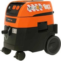
Yellow and black industrial vacuum cleaner with control panel, displayed against orange background (no visible text or symbols)
natural_image
Icon of a person sitting at a desk with an open book, set against an orange background (no text or symbols)Operating Instructions 7
| 1 | Top section |
| 2 | Functional plate (depending on appliance configu-ration) |
| 2a | Rotary switch ON/OFF/Automatic/Vibration |
| 2b | Power socket for electric tools |
| 2c | Volume flow display |
| 2d | Speed setter/pre-selction switch |
| 3 | Cold air inlet |
| 4 | Locking bar |
| 5 | Lock |
| 6 | Connecting line |
| 7 | Container |
| 8 | Suction opening |
| 8a | Sealing plug with a chain |
| 9 | Snap-in locks |
| 10 | Wheels |
| 11 | Steering castors |
| 12 | Filter cassettes |
| 13 | Motor protecion filter |
| 14 | Paper filter bag |
| 15 | Plastic emptying bag |
Protection of the ears carry!
Tests and approvals for M and H suction units
Electro-technical tests need to be performed in accordance with the accident prevention guidelines (BGV A3) and in accordance with DIN VDE 0701 Part 1 and Part 3. These tests need to be performed in regular intervals in accordance with DIN VDE 0702 and after maintenance work or modifications.
At least once a year, a technical dust inspection needs to be performed by the manufacturer or a qualified person, e.g. to check for damage to the filter, leaks, function of the control equipment.
CE-Registration statement
We declare in our own sole responsibility that this product Typ Spit AC 1625 and AC 1630P complies with the EU directives ans definitive standards: Low voltage directive 73/23/EEC with amendments, electromagnetic compatibility directive EN 60335-2-69 with amendments.
Paul van Beek
Ruben Bernaert
Business Manager
Product Manager
ITW Heger
Industriepark
Cardijnlaan 3
B-8600 Diksmuide
Belgien
BEFORE USE
When unpacking, check that the unit is complete and shows no signs of transport damage.
Read all the information carefully. They contain important advice about how to use the unit, safety, maintenance and care. Please keep these operating instructions somewhere safe and pass on to any subsequent owners. We reserve the right to make design and equipment changes.
FIELDS OF APPLICATION
For wet and drying suctioning.
Dust class M vacuum cleaners are suited to suction-ing up/off dry non-flammable dust non-flammable liquids,
wood dust and hazardous dust with AGW's ≥ 0.1 mg/m ^3 .
Dust class H vacuum cleaner are suited to suctioning up/off dry non-flammable dust, carcinogenic and pathogenic particles, non-flammable liquids, wood dust and dusts hazardous to health with AGW's < 0.1 mg/m ^3 .
COMMISSIONING
Switch the unit ON/OFF with the switch ②a in the top section ① (or switch to automatic mode).
Operating field
Depending on the unit configuration, the following functions and settings are available:
0 = Suction unit >off<
I = Suction unit >on<
A = Ready mode for ON/OFF automatic mode.
(Suction unit is switched ON/OFF by the electrical tool)
AC = Ready mode like "A" plus automatic filter cleaning.
Filter cleaning function; in this switch setting the vibrator is activated for approx. 10 sec. and then switches off again automatically.
The power socket ②b is available for connecting an electrical tool.
Caution! The electrical tool must be switched off during connection. The power socket is permanently supplied with voltage when the plug is in the mains socket regardless of the switch setting. In switch setting "0" the power socket could still be used as an extension cable (e.g. for lights).
Connected load: Suction unit and connected unit max. 16 A.
The suction output can be adjusted steplessly using the rotating speed setter ②d.
Pre-selection switch ②d for minimum volume signal (horn and light) for suction units of the class "M" and "H". In mode "A" or "RA", the following settings should be made depending on the diameter of the hose:
| Hose diameter Switch setting | |
| 35 mm 70 m^3/h | |
| 27 mm 40 m^3/h | |
| 21 mm 20 m^3/h |
The speed is not regulated. The suction unit always runs at max. speed
The suction openings of the electrical tools are not standard-ised. There is an adapter available (rubber nozzle or rubber muff) which can be shortened and adjusted to the respective electrical tool.
OPERATION
When the handle pipe is used, the secondary air valve can be used to adjust the suction output.
Dry suctioning
Only suction with a dry filter, unit and accessories so that the dust does not adhere and harden. We recommend using a paper filter bag if soot, cement, plaster, flour or similar substances are suctioned.
Always use the paper filter bag in combination with the filter cartridges.
Wet suctioning
Suction without a paper filter bag. The filter cassettes are suitable for wet suctioning. The installed sensor switches the motor off when the tank is full. Empty the unit as outlined. If the unit is not switched off, the restarting safeguard remains effective. The unit will only be ready for operation again after it has been switched off and switched on again.
- Before emptying, first remove the suction hose from the liquid.
- Due to the high suction output and the streamlined shape of the tank, a little water may escape from the hose after the unit has been switched off.
- For the subsequent dry suction phase, use a dry filter. In case of frequent changes between dry and wet suctioning, we recommend using a second filter set, preferably polyester filter cassettes.
Cleaning the filter
The suction unit is fitted with an electro-magnetic filter cleaning device which can shake off any dust adhered to the folded filter cassettes.
Manual cleaning
The vibration function (switch setting C or AC /switch ②a) should be activated at the latest when the volume flow display ②c (warning lamp) lights up or when the warning signal sounds or when the suction output sinks.
Automatic cleaning (automatic vibration)
Filter cleaning is performed (switch setting AC/switch ②a) automatically during the next working break when the minimum volume flow level is reached.
Emptying the tank
Only permitted with dusts with AGW's > 1 mg/m ^3 .
Switch off ②a, disconnect plug ⑥, open snap locks ⑨. Take top section ① and suction hose from the tank ⑦. Empty the tank.
Paper filter bag
To insert or remove the filter bag/emptying bag, remove the top section ①). To do this, open the side locks ⑨. Only use the paper filter bag for dry suctioning.
Inserting the paper filter bag
- 25 litre tank Push the flange over the suction opening
- 25 l-special tank on AC 1625 M may only be operated with paper filter bags if dust is suctioned up with exposure limits (AGW's) > 0.1 mg/m ^3 .
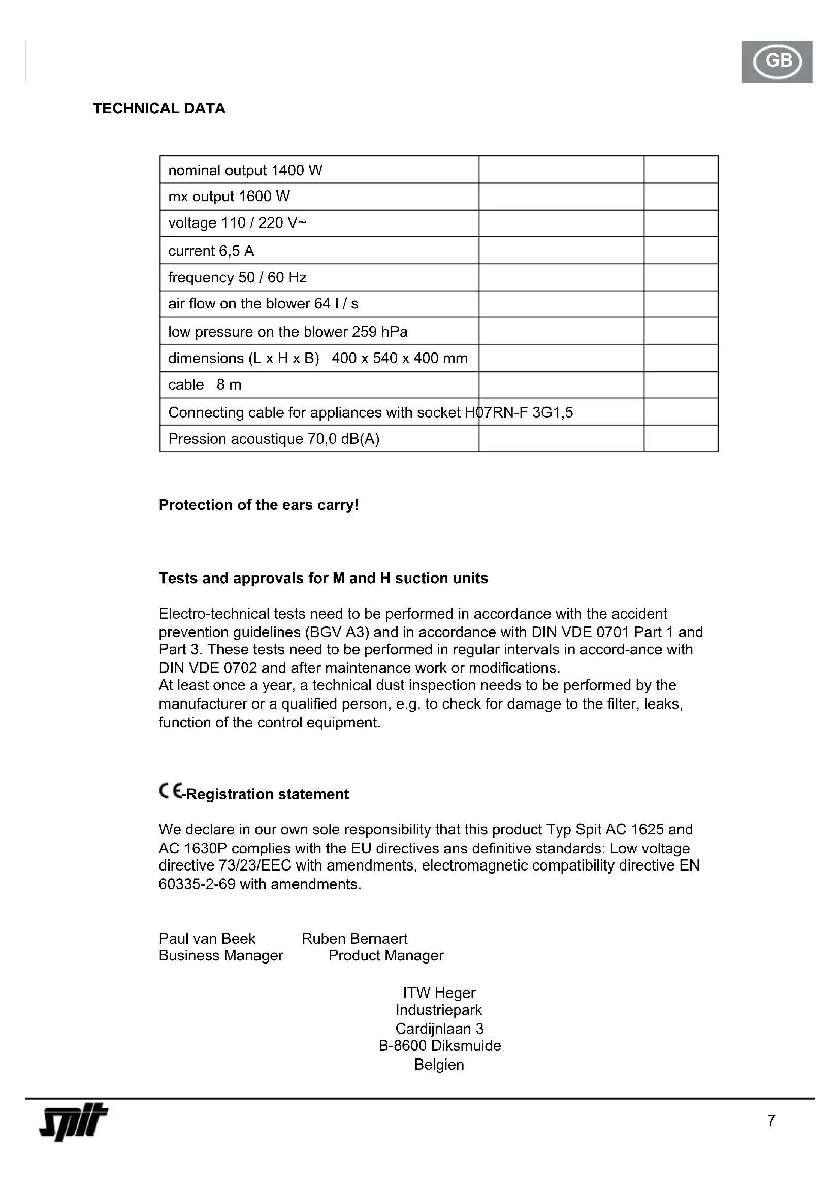
Turn the knob in the suction opening with the marking ▲4 to the top. Push the flange over the suction opening.
text_image
Diagram of car air intake control panel with numbered components and directional arrows indicating rotation or adjustment.Exchanging the paper filter bag
Carefully pull the flange from the suction connections and close the flange.
Turn on the motor before putting down to ensure that any falling suspended dust can be suctioned.
Dispose of the vacuumed material as per the statutory regulations.
Plastic emptying bag
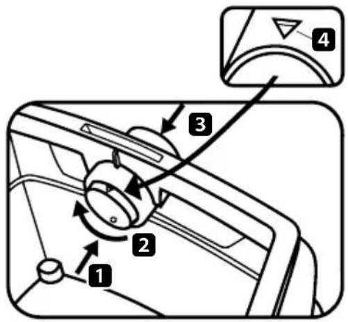
Only the M and H vacuum cleaners with the special tanks and rotary valve in the suction opening AC 1625 M is suited for using plastic emptying bags.
Turn the rotary valve with the round label upwards in the suction opening ● 4.
text_image
Diagram of a car interior showing labeled parts including directional arrows and numbered annotationsOperating the slide valve:
Push the slide valve from inside to the outside 1, turn by 180° 2 (see marking 4) and press from outside through the suction pipes to the inside again 3.
Push the flange over the suction pipes, place the opening of the bag over the edge of the tank.
Exchanging the plastic emptying bag
Detach the suction hose, close the suction opening ⑧ with a plug (Pos. ⑧a).
Remove the top section ①. Switch on the motor before placing on the ground so that any falling dust can also be suctioned. Close the emptying bag with a closing band.
Pull the flange carefully in front of the suction opening and close tight. Dispose of the contents in accordance with the statutory provisions.
CLEANING
Clean the tank and accessories with water.
Wipe the top section ① with a damp cloth.
Allow the tank and the accessories to dry.
Filter cassettes with air pressure do not clean
WARTUNG
If the suction output of the unit decreases and is not improved after the filter cassettes ⑫ are cleaned, (assuming the tank ⑦ is empty and the paper filter bag ⑭ has been exchanged), then it is time to exchange the filter cassettes ⑫.
Apply the vibration function to the filter cassettes w again before exchanging them. Use a coin or another similar object to turn the catch ⑤ on the locking bar ④ 90° in an anticlockwise direction and then press the locking bar ④ backwards. Fold up the hood and lift out the filter cassettes ⑫. Immediately seal the removed filter cassettes in a dust-proof plastic bag and dispose of as per the statutory regulations. Insert new filter cassettes. Fold down the hood again and exert a little pressure to click it back into position.
If the motor protection filter ⑬ is soiled, this is an indication that the filter cassettes are defective. Please exchange both filter cassettes ⑫. Wash out the motor protection filter ⑬ under running water, dry and re-insert.
TROUBLESHOOTING
| Malfunction Possible cause remedy | ||
| Suction output impaired Soiled filter | Paper filter fullTank is fullNozzle, pipe or hose is blocked | cleanexchangeemptyclean |
| Unit will not start Plug in the power | socket?No mains power?Power cable OK?Unit hood closed properly?Has the water sensor switched off? | |
| Plastic emptying bag is sucked onto the filter | Set the knob to pos. ● | |
| If the paper filter bag is inserted dust in the tank with M or H vacuum cleaners | Set the knob to pos. ▲ |
Do not intervene further, contact a SPIT customer service work-shop.
Old appliances contain valuable materials that can be recycled. Do not dispose of such appliances with the normal domestic waste but rather by way of appropriate collecting points.
text_image
Diagram of a car interior showing directional control buttons and a labeled component with numbered partstext_image
Diagram of a car interior showing labeled parts including a knob, directional arrows, and a component with numbered annotations.text_image
Diagram of a car interior showing directional control buttons and a labeled component with numbered parts 1 to 4.text_image
Diagram of a car interior showing labeled parts including directional arrows and numbered componentstext_image
Diagram of car intake control panel with numbered parts and a close-up view of the componenttext_image
Diagram of a car interior showing labeled parts including a knob, directional arrows, and a component with numbered annotations.CE - Registration Statement
Typ Spit AC 1625 en AC 1630P
text_image
Diagram of car air intake system with labeled components including fan, valve, and adjustment knobtext_image
Diagram of a car interior showing labeled parts including directional arrows and numbered annotations
Paul van Beek Director general
text_image
Diagram of a car interior showing labeled parts including a knob, fan, and adjustment knob with numbered annotations.text_image
Diagram of a car interior control panel with numbered parts and directional arrows indicating rotation or adjustment.
Manejo del selector giratorio:
text_image
Diagram of a car interior showing labeled parts including a knob, fan, and adjustment knob with numbered annotations.Troca do saco de filtro de papel
text_image
Diagram of a car interior showing labeled parts including directional arrows and numbered annotations
INNAN APPARATEN ANVÄNDS
text_image
Diagram of a car interior showing labeled parts including a knob, fan, and adjustment knob with numbered annotations.text_image
Diagram of a car interior control panel with numbered parts and directional arrows indicating rotation or adjustment.
text_image
Diagram of car air intake control panel with labeled parts and directional arrowstext_image
Diagram of a car interior showing labeled parts including a knob, directional arrows, and a component with numbered annotations.Sette inn papirfilterposen
text_image
Diagram of car air intake system with numbered components and a control panel labeled 4Skifte ut papirfilterposen
text_image
Diagram of a car interior showing labeled parts including a knob, directional arrows, and a dial indicator.text_image
Diagram of car interior control panel with numbered parts and a close-up view of the top panel showing a curved dial.text_image
Diagram of a car interior showing labeled parts including a knob, directional arrows, and a dial indicator.text_image
Diagram of car air intake system with labeled components and directional arrowstext_image
Diagram of a car interior control panel with numbered parts and directional arrows indicating rotation or adjustment.text_image
Diagram of a car interior showing labeled parts including a knob, fan, and adjustment knob with numbered annotations.text_image
Diagram of a car interior showing labeled parts including a knob, dial, and adjustment knob with numbered annotations.text_image
Diagram of car air intake system with numbered components and directional arrows indicating rotation or adjustmenttext_image
Diagram of a car interior control panel with numbered parts and directional arrows indicating rotation or adjustment.text_image
Diagram of a car interior showing labeled parts including a knob, fan, and adjustment knob with numbered annotations.text_image
Diagram of a car interior showing labeled parts including a knob, directional arrows, and a component with numbered annotations.text_image
Diagram of a car interior showing labeled parts including controls and a component with numbered annotationstext_image
Diagram of a car interior control panel with numbered parts and directional arrows indicating rotation or adjustment.text_image
Diagram of car air intake system with labeled components and directional arrows indicating rotation or movementZamena papirnate filterske kesice
Prirubnicu oprezno skinite sa usisnog nastavka i zatvorite ga. Motor uključite pre odlaganja, da bi mogla da se usisa eventualno nastala lebdeća prašina. Usisani materijal zbrinite prema zakonskim odredbama.
Plastična kesica za pražnjenje
Samo M i H usisivači sa posebnom posudom i okretnim klizačem u usisnom otvoru, tipovi AC 1625 M, prikladni su za upotrebu plastične kesice za pražnjenje.
text_image
Diagram of a car interior showing labeled parts including directional arrows and numbered calloutsPosluživanje obrtnog šibera:
Obrtni šiber iznutra potisnuti prema vani 1, okrenuti za 180° 2 (vidi oznaku 4) i izvana opet kroz nastavke za usisavanje potisnuti unutra 3.
Prirubnicu potisnite preko usisnog nastavka, gornji otvor kesice položite preko ruba posude
text_image
Diagram of a car interior showing numbered components and directional arrows indicating motion or movement.Zamjena papirne filtarske vrećice
Prirubnicu oprezno skinuti s usisnog nastavka i zatvoriti ju. Motor uključiti prije odlaganja, kako bi se mogla usisati eventualno nastala lebdeća prašina. Usisani materijal zbrinuti prema zakonskim odredbama..
text_image
Diagram of a car interior showing labeled parts including directional arrows and numbered annotationstext_image
Diagram of car air intake control panel with labeled parts including fan, knob, and adjustment knobZamenjava papirnate filtrske vrečke
General Manager Product Manager
ITW Heger
Industriepark
Cardijnlaan 3
B-8600 Diksmuide
Belgien

ПЕРЕД ЭКСПЛУАТАЦИЕЙ
text_image
Diagram of car interior control panel with numbered parts and a magnified view of the top-right componenttext_image
Diagram of a car interior showing labeled parts including a knob, directional arrows, and a component with numbered annotations.text_image
1 2 3 4 5vtext_image
Diagram of a car interior showing labeled parts including a knob, directional arrows, and a dial indicator.text_image
Diagram of car interior control knob with numbered parts and a magnified view of the dashboard dialسعة 25 لترّا
•
text_image
Diagram of a car interior showing labeled parts including a knob, directional arrows, and a dial indicator.natural_image
Orange background with a white stylized ITW helmet icon (no text or symbols)Serial n° / Identification
This manual should always be retained with the tool.
Spit reserves the right to modify the characteristics of its products at any time. The photographs may show equipment or accessories supplied as options and not included with standard versions.