
AutoLineLaser 3D Plus - Laser level Laserliner - Free user manual and instructions
Find the device manual for free AutoLineLaser 3D Plus Laserliner in PDF.
| Product type | 3D laser level |
| Brand | Laserliner |
| Model | AutoLineLaser 3D Plus |
| Dimensions (W x H x D) | 85 x 130 x 160 mm |
| Weight (batteries included) | 820 g |
| Power supply | 4 AA alkaline batteries 1.5V (LR6) |
| Battery life (3 beams) | approx. 6 h |
| Battery life (2 beams) | approx. 10 h |
| Battery life (1 beam) | approx. 25 h |
| Laser class | 2M |
| Laser power | < 5 mW |
| Laser wavelength | 640 nm |
| Self-leveling range | ± 2.5° |
| Accuracy | ± 0.2 mm/m |
| Working range (interior) | 20 m |
| Working range with receiver | 50 m |
| Working temperature | 0°C to +50°C |
| Storage temperature | -10°C to +70°C |
| Main functions | Horizontal line 360°, two vertical lines 360°, tilt mode, manual receiver mode, self-leveling |
| Tripod thread | 5/8" (back) |
| Maintenance and cleaning | Check calibration regularly; clean with a soft cloth; store in case |
| Safety | Do not look directly into the beam; keep out of reach of children; turn off and lock transport |
| Spare parts and repairability | Contact Umarex-Laserliner customer service for calibration and repairs |
| Warranty and compliance | Complies with EU standards; selective collection WEEE |
Frequently Asked Questions - AutoLineLaser 3D Plus Laserliner
User questions about AutoLineLaser 3D Plus Laserliner
0 question about this device. Answer the ones you know or ask your own.
Ask a new question about this device
Download the instructions for your Laser level in PDF format for free! Find your manual AutoLineLaser 3D Plus - Laserliner and take your electronic device back in hand. On this page are published all the documents necessary for the use of your device. AutoLineLaser 3D Plus by Laserliner.
USER MANUAL AutoLineLaser 3D Plus Laserliner
natural_image
Exterior view of a Laserliner 3D device (no visible text or symbols on the device body)AUTOMATIC
LEVEL

Laser
640 nm

lock
1H360° 2V360°
natural_image
Two 3D wireframe cubes with shading, one larger and one smaller, labeled 'S' (no text or symbols on the cubes themselves)Laserliner®
Innovation in Tools
DE
02
GB
08
NL
14
DK
20
FR
26
ES
32
IT
38
PL
44
FI
50
PT
56
SE
62
NO
68
TR
74
RU
80
UA
86
CZ
92
EE
98
LV
04
LT
10
RO
16
BG
22
GR
28
!
natural_image
Interior view of a white handheld device showing internal components with battery and indicator lights (no text or symbols visible)

Read the operating instructions and the enclosed brochure „Guarantee and additional notices“ completely. Follow the instructions they contain. Safely keep these documents for future reference.
Three-dimensional laser with a horizontal and two vertical 360° laser circles and slope function for aligning tiles, wall studding, windows, doors etc.
General safety instructions
Laser radiation! Do not stare into the beam or observe it directly with optical instruments. Class 2M laser < 5 mW · 640 nm EN 60825-1:2007-10
Caution: Do not look directly into the beam. Lasers must be kept out of reach of children. Never intentionally aim the device at people. This is a quality laser measuring device and is 100% factory adjusted within the stated tolerance. For reasons of product liability, we must also draw your attention to the following: Regularly check the calibration before use, after transport and after extended periods of storage. We also wish to point out that absolute calibration is only possible in a specialist workshop. Calibration by yourself is only approximate and the accuracy of the calibration will depend on the care with which you proceed.
!
Always turn off all lasers and latch the pendulum in place before transporting, ON/OFF switch in its „OFF“ position!
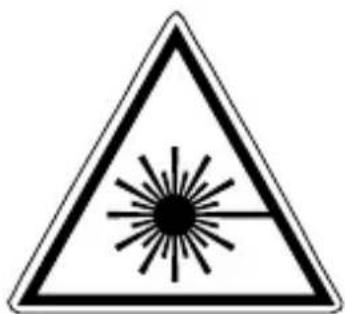
1 Inserting batteries
Open the battery compartment and insert batteries (4 x type AA) according to the symbols. Be sure to pay attention to polarity.
natural_image
Interior view of a white handheld device showing internal components with labeled buttons (no text or symbols beyond basic labels)
1 Laser output windows
2 Battery compartment (bottom)
3 ON / OFF switch; transport retainer; Slope mode
4 5/8" tripod threads (bottom)
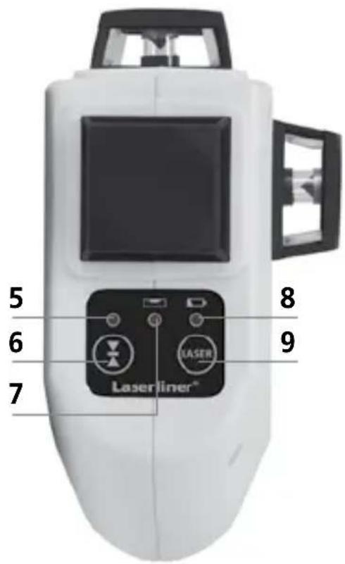
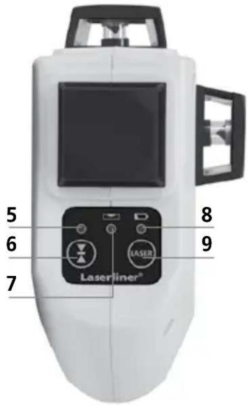
5 LEDhand receiver mode
6 Hand receiver mode on / off
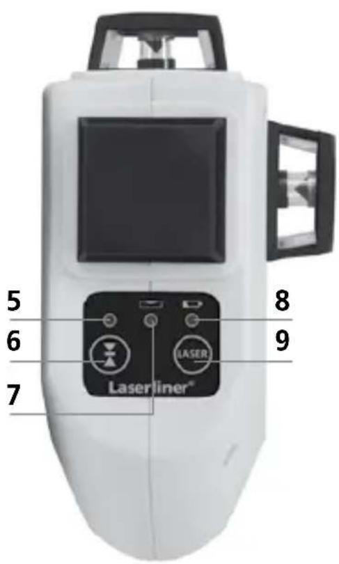
7 LED slope mode
LED on: Mode on
LED off: Mode off
8 Battery charge
9 Laser line selection button
2 Horizontal and vertical levelling
Release the transport restraint, set the ON/OFF switch to „ON“. The horizontal laser line appears. The laser lines can be switched on individually with the selection button.
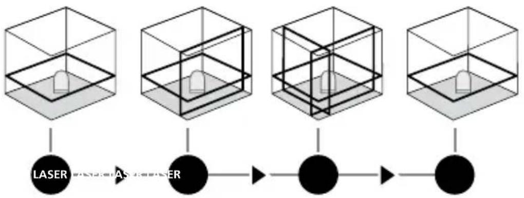
flowchart
graph LR
    A["3D Cube 1"] --> B["LASER"]
    C["3D Cube 2"] --> D["AS System"]
    E["3D Cube 3"] --> F["●"]
    G["3D Cube 4"] --> H["●"]
!
The transport restraint must be released for horizontal and vertical levelling. The laser lines flash and a signal sounds as soon as the device is outside the automatic levelling range of 2,5^ . Position the device such that it is within the levelling range.
3 Hand receiver mode
Optional: Working with the laser receiver RX
Use an RX laser receiver (optional) to carry out levelling at great distances or when the laser lines are no longer visible. To work with a laser receiver, switch the line laser to hand-held receiver mode by keeping button 6 (hand-held receiver mode on / off) pressed. The laser lines will now pulsate with high frequency, making the laser lines darker. The laser receiver can detect these pulsating laser lines.
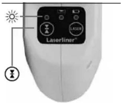
!
Observe the laser receiver's operating instructions for line lasers.
!
Due to the special optics required to generate a continuous 360^ laser line, the underlying technology may cause differences in brightness in different areas of the line. This may lead to different ranges in hand receiver mode.
4 Slope mode
Do not release the transportation safety device. Slide the ON/OFF switch into the centre position and select the laser using the selection button. Sloping planes and tilts
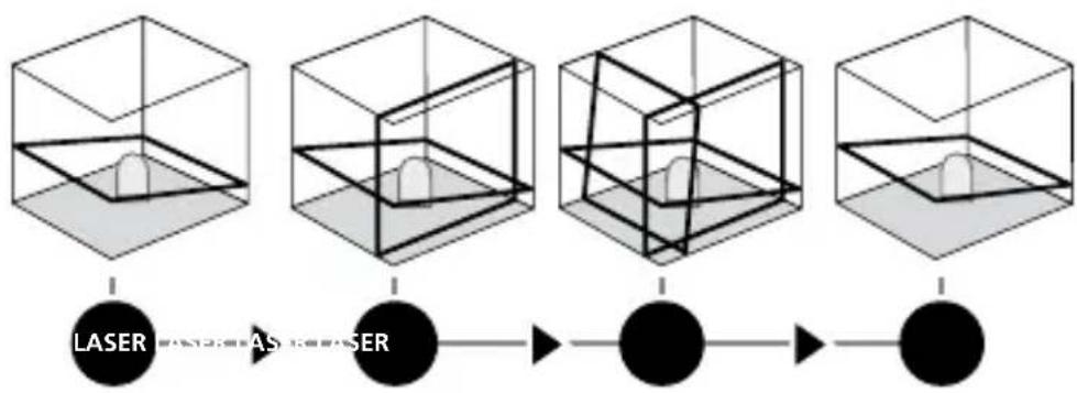
flowchart
graph LR
    A["1"] --> B["2"]
    B --> C["3"]
    C --> D["4"]
    D --> E["5"]
    E --> F["6"]
    style A fill:#f9f,stroke:#333
    style B fill:#f9f,stroke:#333
    style C fill:#f9f,stroke:#333
    style D fill:#f9f,stroke:#333
    style E fill:#f9f,stroke:#333
    style F fill:#f9f,stroke:#333
can now be measured. In this mode, the laser lines no longer align automatically. This is signalised by the laser lines flashing. In addition, the LED light (7) remains red.
Technical data
| Self-levelling range ± 2,5° | |
| Accuracy ± 0,2 mm / m | |
| Operating range (depending on room illumination) 20 m | |
| Working range with hand receiver (depends on how the technology affects the difference in brightness) | 50 m |
| Laser wavelength 640 nm | |
| Laser class / line laser output power 2M / < 5 mW | |
| Power supply | 4 x 1.5V alkaline batteries (type AA, LR6) |
| Operating time with 3 laser levels with 2 laser levels with 1 laser level | approx. 6 hours approx. 10 hours approx. 25 hours |
| Operating temperature 0°C ... +50°C | |
| Storage temperature -10°C ... +70°C | |
| Dimensions (W x H x D) 85 x 130 x 160 mm | |
| Weight (incl. batteries) 820 g | |
Subject to technical changes without notice. 04.2014
Preparing the calibration check
It is possible for you to check the calibration of the laser. To do this, position the device midway between 2 walls, which must be at least 5 metres apart. Switch the device on (Laser cross ON). The best calibration results are achieved if the device is mounted on a tripod.
- Mark point A1 on the wall.
- Turn the device through 180^ and mark point A2. You now have a horizontal reference between points A1 and A2.
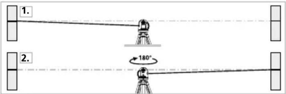
Performing the calibration check
-
Position the device as near as possible to the wall at the height of point A1.
-
Turn the device through 180^ and mark point A3. The difference between points A2 and A3 is the tolerance.
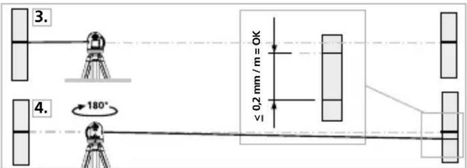

If points A2 and A3 are more than 0.2 mm / m, the device is in need of calibration. Contact your authorised dealer or else the UMAREX-LASERLINER Service Department.
Checking the vertical line
Position the device about 5 m from a wall. Fix a plumb bob with a line of 2.5 m length on the wall, making sure that the bob can swing freely. Switch on the device and align the vertical laser to the plumb line. The precision is within the specified tolerance if the deviation between the laser line and the plumb line is not greater than ± 1.5 mm.
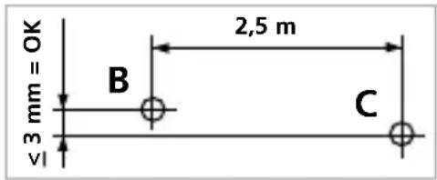
Checking the horizontal line
Position the device about 5 m from a wall and switch on the cross laser. Mark point B on the wall. Turn the laser cross approx. 2.5 m to the right and mark point C. Check whether the horizontal line from point C is level with point B to within ± 3 mm. Repeat the process by turning the laser to the left.

Regularly check the calibration before use, after transport and after extended periods of storage.
Guarantee, product care and disposal
This device complies with all necessary standards for the free movement of goods within the EU.
This product is an electric device and must be collected separately for disposal according to the European Directive on waste electrical and electronic equipment.
Further safety and supplementary notices at:
www.laserliner.com/info

!
natural_image
Interior view of a white handheld device showing internal components with labeled buttons (no text or symbols beyond basic labels)
!
Laserstråling!
natural_image
Diagram of a white handheld device with internal components and labeled ports (no text or symbols present)
1 Lasers udgangsrude
2 Batterirum (underside)
3 TIL/FRA-kontakten; medtransportsikring; Hældningsmodus
4 5/8" gevindbøsning (underside)

Hvis A2 og A3 ligger mere end 0,2 mm / m fra hinanden, skal der foretages en justering. Indlevér laseren til forhandleren, som sørger for det videre fornødne, eller kontakt serviceafdelingen hos UMAREX-LASERLINER.
Kontrol af lodret laserlinie
natural_image
Diagram of a white handheld device with internal components and labeled pins (no text or symbols beyond basic labels)

natural_image
Interior view of a white handheld device showing internal components with labeled buttons (no text or symbols beyond basic labels)

natural_image
Interior view of a white handheld device showing internal components with no visible text or symbols

natural_image
Diagram of a white handheld device with internal components and labeled ports (no text or symbols present)

natural_image
Internal view of a white handheld device with internal components and labeled ports (no text or symbols visible)

natural_image
Interior view of a white handheld device showing internal components with battery and indicator lights (no text or symbols visible)

natural_image
Internal view of a white handheld device with internal components and labeled ports (no text or symbols visible)

natural_image
Interior view of a white handheld device showing internal components with battery and indicator lights (no text or symbols visible)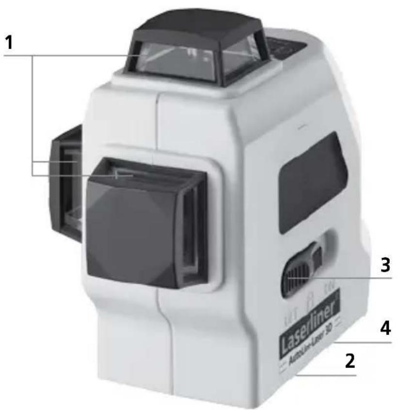
1 Laserstrålehull
2 Batterirom (underside)
3 PÅ- / AV bryter; transportsikring; hellingsmodus
4 Stativgjenger 5/8" (underside)
5 LED manuell
mottakermodus
6 Håndmottaker-
modus PÅ / AV


natural_image
Diagram of a white handheld device with internal components and labeled ports (no text or symbols present)

natural_image
Internal view of a white handheld device with internal components and labeled ports (no text or symbols visible)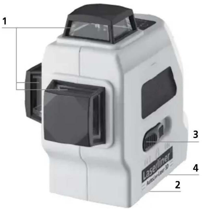
!
natural_image
Interior view of a white handheld device showing internal components with labeled buttons (no text or symbols beyond basic labels)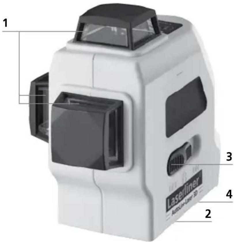

natural_image
Internal view of a white portable flashlight with internal components and labeled ports (no text or symbols beyond basic labels)

Laserkiirgus! Mitte vaadata kiirt ega jälgida seda optiliste instrumentidega. Laseriklass 2M < 5 mW · 640 nm EN 60825-1:2007-10
natural_image
Internal view of a white portable flashlight with internal components and labeled ports (no text or symbols beyond basic labels)
1 Laserkiire aken
2 Patareide kast (alakülg)
3 SISSEVÄLJA lüliti; Transpordipolt; Kalderežiim

natural_image
Interior view of a white handheld device showing internal components with battery and indicator lights (no text or symbols visible)

natural_image
Interior view of a white handheld device with internal components and labeled ports (no text or symbols visible)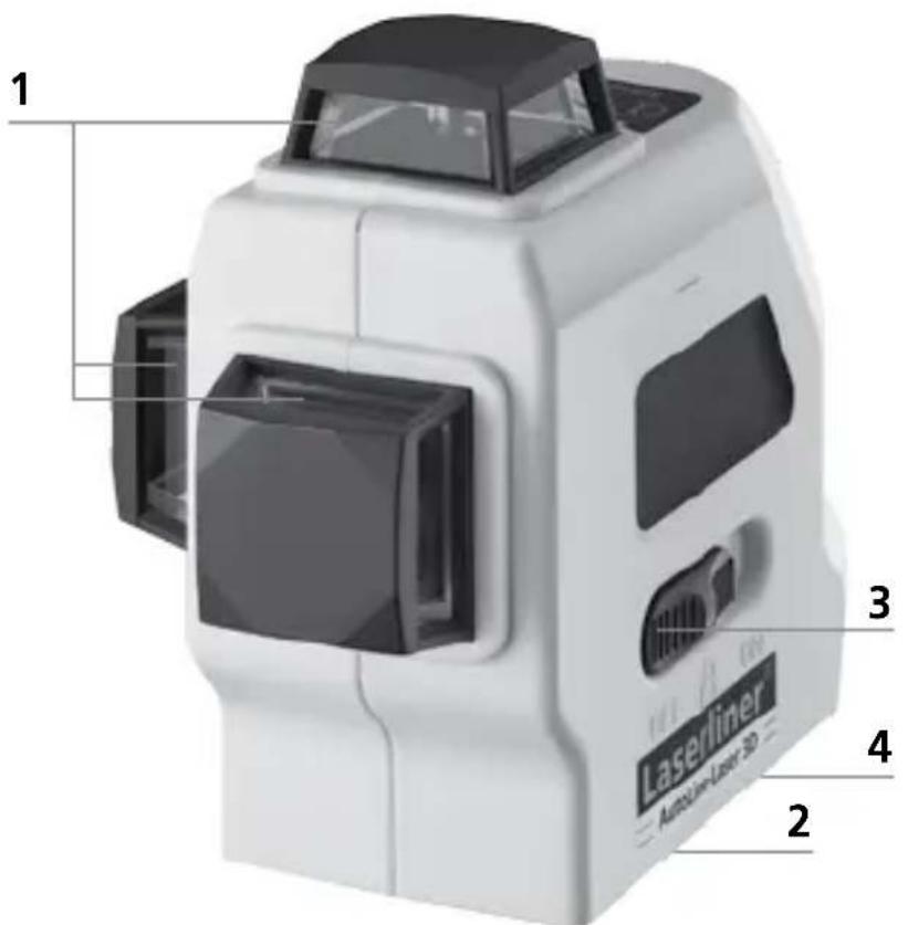

natural_image
Interior view of a white handheld device showing internal components with battery and indicator lights (no text or symbols visible)

natural_image
Interior view of a white portable flashlight with internal components and labeled buttons (no text or symbols beyond basic labels)


natural_image
Interior view of a white handheld device with internal components and labeled ports (no text or symbols visible)

flowchart
graph LR
    A["3D Cube with shaded faces"] --> B["3D Cube with internal lines"]
    B --> C["2D Circular Structure with circular ends"]
    C --> D["2D Circular Structure with circular ends"]

natural_image
Interior view of a modern building with large windows and tiled flooring, featuring a camera rig and glass doors (no text or symbols visible)SERVICE

Umarex GmbH & Co KG
-Laserliner-
- LEVEL
- Three-dimensional laser with a horizontal and two vertical 360° laser circles and slope function for aligning tiles, wall studding, windows, doors etc.
- General safety instructions
- Inserting batteries
- Horizontal and vertical levelling
- Hand receiver mode
- Optional: Working with the laser receiver RX
- Slope mode
- Preparing the calibration check
- Performing the calibration check
- Checking the vertical line
- Checking the horizontal line
- Guarantee, product care and disposal
- Kontrol af lodret laserlinie
- Umarex GmbH & Co KG
Brand : Laserliner
Model : AutoLineLaser 3D Plus
Category : Laser level