
GCL 25 Professional - Laser level BOSCH - Free user manual and instructions
Find the device manual for free GCL 25 Professional BOSCH in PDF.
| Product Type | Point and line laser level |
| Model | GCL 25 Professional |
| Article Number | 3 601 K66 B00 |
| Working Range (Laser Lines) | 10 m |
| Working Range (Horizontal Point Beams) | 30 m |
| Working Range (Point Beam Upward) | 10 m |
| Working Range (Point Beam Downward) | 5 m |
| Levelling Accuracy (Lines & Horizontal Points) | ±0.3 mm/m |
| Levelling Accuracy (Vertical Points) | ±0.5 mm/m |
| Self-levelling Range | ±4° |
| Levelling Time | < 4 s |
| Operating Temperature | -10°C to +50°C |
| Storage Temperature | -20°C to +70°C |
| Laser Class | 2 (IEC 60825-1) |
| Laser Type | 635 nm, < 1 mW |
| Battery | 4 x 1.5 V LR06 (AA) |
| Battery Life (Cross & Point-Line) | 12 h |
| Battery Life (5-Point) | 24 h |
| Battery Life (Line Operation) | 30 h |
| Weight (EPTA 01/2003) | 0.6 kg |
| Dimensions (L x W x H) | 155 x 56 x 118 mm |
| Protection Class | IP 54 (dust & splash water) |
| Tripod Mount | 1/4" and 5/8" |
| Automatic Shut-off | After approx. 30 min (deactivatable) |
| Operating Modes | Cross & point-line, 5-point, horizontal line, vertical line |
Frequently Asked Questions - GCL 25 Professional BOSCH
User questions about GCL 25 Professional BOSCH
0 question about this device. Answer the ones you know or ask your own.
Ask a new question about this device
Download the instructions for your Laser level in PDF format for free! Find your manual GCL 25 Professional - BOSCH and take your electronic device back in hand. On this page are published all the documents necessary for the use of your device. GCL 25 Professional by BOSCH.
USER MANUAL GCL 25 Professional BOSCH
natural_image
3D rendering of a Bosch industrial sensor module (no text or symbols visible)Robert Bosch GmbH
Power Tools Division
70745 Leinfelden-Echterdingen
Germany
www.bosch-pt.com
he Originals Engineering
English ......Page 11
Français....Page 17
GCL 25
natural_image
Diagram of a camera setup with a tripod and 3D box layout, no text or symbols present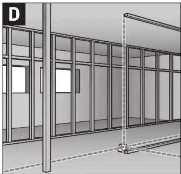
natural_image
Architectural rendering of a building facade with glass panels and a vertical post (no text or symbols)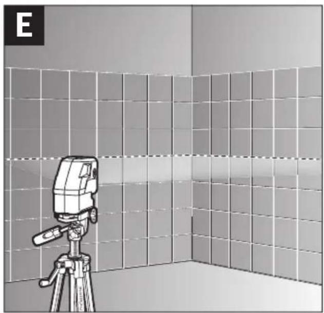
natural_image
Illustration of a camera on a tripod in a tiled room, no text or symbols present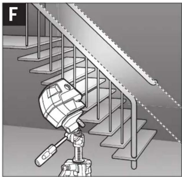
natural_image
Illustration of a robotic device positioned on a staircase with metal railings (no text or symbols)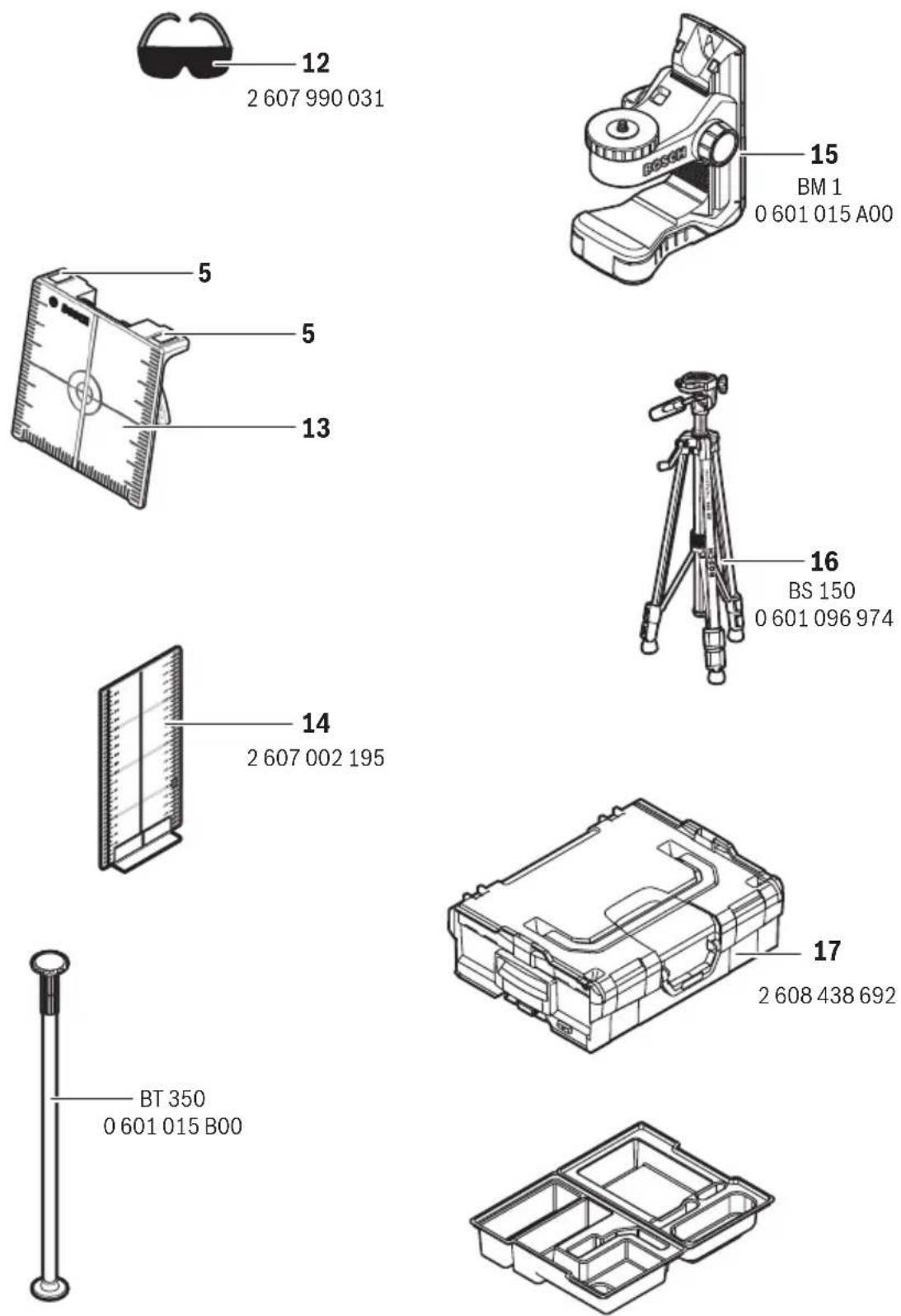
Deutsch
Sicherheitshinweise

Working safely with the measuring tool is possible only when the operating and safety information are read completely and the instructions contained therein are strictly followed. Never make warning labels on the measuring tool unrecognisable. SAVE THESE INSTRUCTIONS.
- Caution – The use of other operating or adjusting equipment or the application of other processing methods than those mentioned here, can lead to dangerous radiation exposure.
The measuring tool is provided with a warning label in English (marked with number 10 in the representation of the measuring tool on the graphics page).
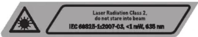
▶ Do not direct the laser beam at persons or animals and do not stare into the laser beam yourself. This measuring tool produces laser class 2 laser radiation according to IEC 60825-1. This can lead to persons being blinded.
▶ Do not use the laser viewing glasses as safety goggles. The laser viewing glasses are used for improved visualisation of the laser beam, but they do not protect against laser radiation.
▶ Do not use the laser viewing glasses as sun glasses or in traffic. The laser viewing glasses do not afford complete UV protection and reduce colour perception.
▶ Have the measuring tool repaired only through qualified specialists using original spare parts. This ensures that the safety of the measuring tool is maintained.
▶ Do not allow children to use the laser measuring tool without supervision. They could unintentionally blind other persons or themselves.
▶ Do not operate the measuring tool in explosive environments, such as in the presence of flammable liquids, gases or dusts. Sparks can be created in the measuring tool which may ignite the dust or fumes.

Keep the laser target plate 13 away from cardiac pacemakers. The magnets on the laser target plate generate a field that can impair the function of cardiac pacemakers.
▶ Keep the laser target plate 13 away from magnetic data medium and magnetically-sensitive equipment. The effect of the magnets on the laser target plate can lead to irreversible data loss.
Product Description and Specifications
Please unfold the fold-out page with the representation of the measuring tool and leave it unfolded while reading the operating instructions.
Intended Use
The measuring tool is intended for determining and checking horizontal and vertical lines as well as plumb points.
Product Features
The numbering of the product features shown refers to the illustration of the measuring tool on the graphic page.
1 Exit opening for laser beam
2 Operating mode button
3 Battery low indicator
4 On/Off switch
5 Magnets
6 Tripod mount 5/8"
7 Tripod mount 1/4"
8 Latch of battery lid
9 Battery lid
10 Laser warning label
11 Serial number
12 Laser viewing glasses*
13 Laser target plate
14 Measuring plate with stand*
15 Universal holder*
16 Tripod*
17 Case
* The accessories illustrated or described are not included as standard delivery.
Technical Data
Point and line laser GCL 25
| Article number | 3 601 K66 B00 |
| Working range1) | |
| – Laser lines | 10 m |
| – Horizontal point beams | 30 m |
| – Point beam, upward | 10 m |
| – Point beam, downward | 5 m |
| Levelling accuracy | |
| – Laser lines and horizontal point beams | ±0.3 mm/m |
| – Vertical point beams | ±0.5 mm/m |
| Self-levelling range, typically | ±4° |
| Levelling duration, typically | <4s |
| Operating temperature | -10°C ... +50°C |
| Storage temperature | -20°C ... +70°C |
| Relative air humidity, max. | 90% |
| Laser class | 2 |
| Laser type | 635 nm, <1 mW |
| C6 | 1 |
| Tripod mount | 1/4", 5/8" |
| Batteries | 4 x 1.5 VLR06 (AA) |
1) The working range can be decreased by unfavourable environmental conditions (e.g. direct sun irradiation).
The measuring tool can be clearly identified with the serial number 11 on the type plate.
Point and line laser GCL 25
| Battery life for the operating modes | |
| - Cross and point-line operation | 12 h |
| - 5-point operation | 24 h |
| - Line operation | 30 h |
| Weight according to EPTA-Procedure 01/2003 | 0.6 kg |
| Dimensions(length x width x height) | 1 5 5 x 5 6 x 1 1 8 mm |
| Degree of protection | IP 54 (dust and splash water protected) |
1) The working range can be decreased by unfavourable environmental conditions (e.g. direct sun irradiation).
The measuring tool can be clearly identified with the serial number 11 on the type plate.
Assembly
Inserting/Replacing the Battery
Alkali-manganese batteries are recommended for the measuring tool.
To open the battery lid 9, slide the latch 8 in the direction of the arrow and fold the battery lid up. Insert the batteries.
When inserting, pay attention to the correct polarity according to the representation on the inside of the battery lid.
When the batteries are low, the battery low indicator 3 flashes red. Additionally, the laser beams flash for approx. 5 s every 10 minutes. When the flashing initially begins, the measuring tool can be operated for approx. 1 more hour. When the batteries become empty, the laser beams flash one more time directly prior to the automatic shut-off.
Always replace all batteries at the same time. Only use batteries from one brand and with the identical capacity.
Remove the batteries from the measuring tool when not using it for extended periods. When storing for extended periods, the batteries can corrode and discharge themselves.
Operation
Initial Operation
▶ Protect the measuring tool against moisture and direct sun light.
Do not subject the measuring tool to extreme temperatures or variations in temperature. As an example, do not leave it in vehicles for long time. In case of large variations in temperature, allow the measuring tool to adjust to the ambient temperature before putting it into operation. In case of extreme temperatures or variations in temperature, the accuracy of the measuring tool can be impaired.
- Avoid heavy impact or falling of the measuring tool. After heavy exterior impact on the measuring tool, an accuracy check should always be carried out before continuing to work (see “Levelling Accuracy”).
▶ Switch the measuring tool off during transport. When switching off, the levelling unit, which can be damaged in case of intense movement, is locked.
Switching On and Off
To switch on the measuring tool, slide the On/Off switch 4 to the “☐ on” position (when working without automatic ling) or to the “☐ on” position (when working with automatic levelling). Immediately after switching on, the measuring tool sends laser beams out of the exit openings 1.
▶ Do not point the laser beam at persons or animals and do not look into the laser beam yourself, not even from a large distance.
To switch off the measuring tool, slide the On/Off switch 4 to the "off" position. When switching off, the levelling unit is locked.
Deactivating the Automatic Shut-off
When no button on the measuring tool is pressed for approx. 30 minutes, the measuring tool automatically switches off to save the batteries.
To switch on the measuring tool after automatic shut-off, either slide the On/Off switch 4 to the "off" position and then switch the measuring tool on again or press the operating mode button 2 once.
To deactivate the automatic shut-off, keep the operating mode button 2 pressed for at least 3 s (while the measuring tool is switched on). Deactivation of the automatic shut-off is confirmed by brief flashing of the laser beams.
▶ Do not leave the switched on measuring tool unattended and switch the measuring tool off after use. Other persons could be blinded by the laser beam.
To activate the automatic shut-off, switch the measuring tool off and then on again.
Operating Modes
The measuring tool has several operating modes between which you can switch at any time:
- Cross and point-line operation: The measuring tool generates a horizontal and a vertical laser line facing toward the front as well as a vertical point beam each facing upward and downward, and a horizontal point beam each facing toward the front and to both sides.
- 5-point operation: The measuring tool generates a vertical point beam each facing upward and downward, as well as a horizontal point beam each facing toward the front and to both sides.
– Horizontal line operation: The measuring tool generates a horizontal laser line facing frontward. - Vertical line operation: The measuring tool generates a vertical laser line facing frontward.
All point beams run at a 90^ angle to each other; the laser lines also cross each other at a 90^ angle.
After switching on, the measuring tool is in cross-line and point-line operation. To change the operating mode, press the operating mode button 2.
All operating modes can be selected both with and without automatic levelling.
Automatic Levelling
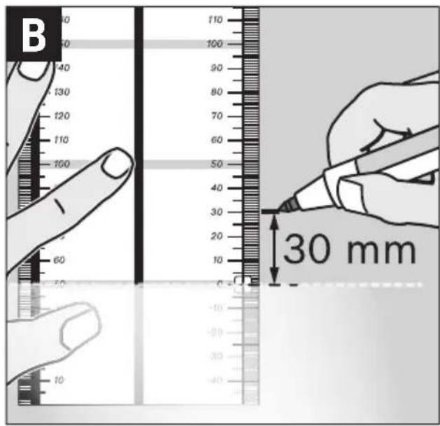
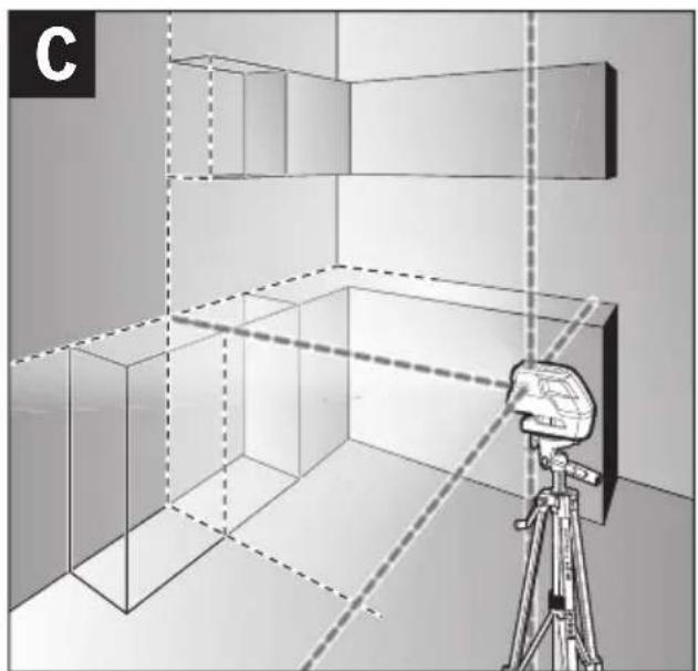
Working with Automatic Levelling (see figures C–E)
Position the measuring tool on a level and firm support, attach it to the holder 15 or to the tripod 16.
When working with automatic levelling, push the On/Off level switch 4 to the "on" position.
After switching on, the automatic levelling function automatically compensates irregularities within the self-levelling range of ±4^ . The levelling is finished as soon as the laser points or laser lines do not move any more.
If the automatic levelling function is not possible, e.g. because the surface on which the measuring tool stands deviates by more than 4^ from the horizontal plane, the laser beams flash. This alarm is deactivated within 10 s after switching on, in order to allow adjustment of the measuring tool.
Set up the measuring tool in level position and wait for the self-levelling to take place. As soon as the measuring tool is within the self-levelling range of ±4^ , the laser beams light up continuously.
In case of ground vibrations or position changes during operation, the measuring tool is automatically levelled in again. To avoid errors by moving the measuring tool, check the position of the laser beams with regard to the reference points upon re-levelling.
Working without Automatic Levelling (see figure F)
For work without automatic levelling, push the On/Off switch 4 to the “on” position. When the automatic levelling is switched off, the laser lines flash continuously.
When automatic levelling is switched off, you can hold the measuring tool freely in your hand or place it on an inclined surface. The laser beams no longer necessarily run vertical to each other.
Levelling Accuracy
Influences on Accuracy
The ambient temperature has the greatest influence. Especially temperature differences occurring from the ground upward can divert the laser beam.
As thermal fluctuation is largest close to the ground, the measuring tool, if possible, should be mounted on a commercially available tripod and placed in the centre of the working area.
Apart from exterior influences, device-specific influences (such as heavy impact or falling down) can lead to deviations. Therefore, check the accuracy of the measuring tool each time before starting your work.
When the accuracy of the horizontal point beams is within the maximum allowed deviation, then the accuracy of the vertical point beams and the laser lines is thus also checked.
Should the measuring tool exceed the maximum deviation during one of the tests, please have it repaired by a Bosch after-sales service.
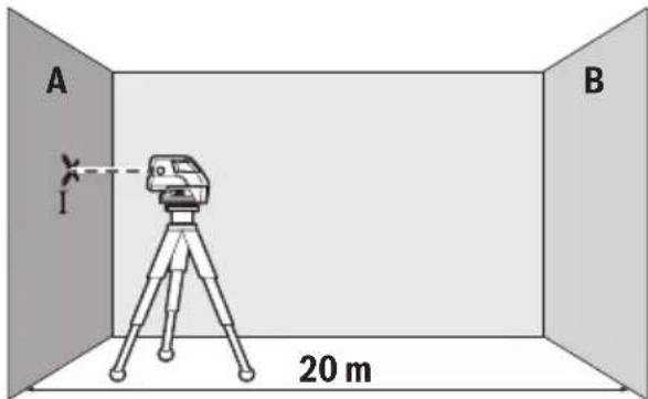
Checking the Horizontal Levelling Accuracy of the Lateral Axis
A free measuring distance of 20 m on a firm surface in front of a wall is required for the check.
- Mount the measuring tool onto the holder or a tripod, or place it on a firm and level surface at a distance of 20m to the wall. Switch the measuring tool on and select 5-point operation.
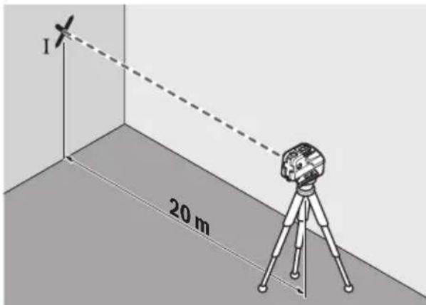
- Direct one of the two lateral laser beams, that run alongside the lateral axis of the measuring tool, at the wall. Allow the measuring tool to level in. Mark the centre of the laser beam on the wall (point I).

- Rotate the measuring tool by approx. 180^ without changing its height. Allow it to level in and mark the centre point of the other lateral laser beam on the wall (point II). Take care that point II is as vertical as possible above or below point I.
- The difference d of both marked points I and II on the wall results in the actual height deviation of the measuring tool alongside the lateral axis.
On the measuring distance of 2 × 20 m = 40 m , the maximum allowable deviation is:
40 m x ± 0.3 mm/m = ±12 mm.
Thus, the difference d between points I and II may not exceed 12 mm (max.).
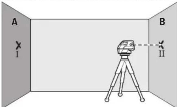
Checking the Horizontal Levelling Accuracy of the Longitudinal Axis
A free measuring distance of 20 m on a firm surface between two walls A and B is required for the check.
- Mount the measuring tool onto the holder or a tripod, or place it on a firm and level surface close to wall A. Switch the measuring tool on and select 5-point operation.
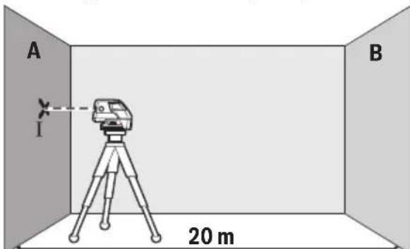
- Direct the horizontal laser beam, which runs parallel to the longitudinal axis of the measuring tool, at the close wall A. Allow the measuring tool to level in. Mark the centre of the laser beam on the wall (point 1).
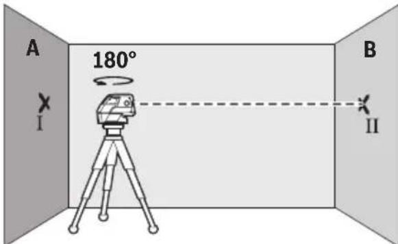
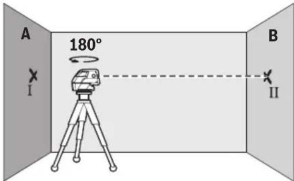
- Turn the measuring tool around by 180^ , allow it to level in and mark the centre point of the laser beam on the opposite wall B (point II).
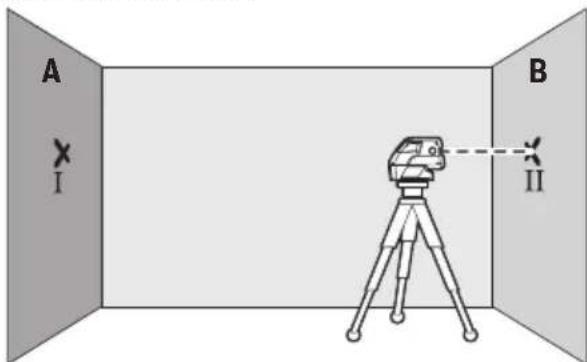
- Without turning the measuring tool, position it close to wall B. Switch the measuring tool on and allow it to level in.
- Align the height of the measuring tool (using the tripod or by underlaying, if required) in such a manner that the centre point of the laser beam is projected exactly against the previously marked point II on wall B.
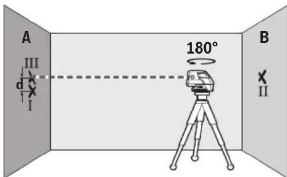
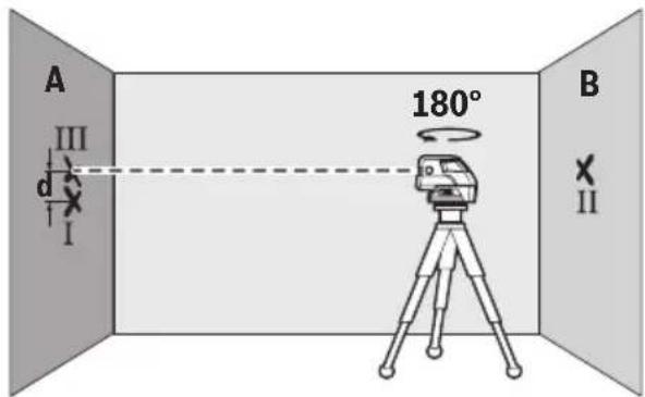
- Rotate the measuring tool by 180^ without changing the height. Allow it to level in and mark the centre point of the laser beam on wall A (point III). Take care that point III is as vertical as possible above or below point I.
- The difference d of both marked points I and III on wall A results in the actual height deviation of the measuring tool alongside the Longitudinal axis.
On the measuring distance of 2 x 20 m = 40 m, the maximum allowable deviation is: 40 m x ±0.3 mm/m = ±12 mm.
Thus, the difference d between points I and III may not exceed 12 mm (max.).
Working Advice
For marking, always use only the centre of the laser point or the laser line. The size of the laser point as well as the width of the laser line change with distance.
Working with the Tripod (Accessory)
A tripod offers a stable, height-adjustable measuring support. Position the measuring tool with the 1/4" tripod mount 7 onto the thread of the tripod 16 or a commercially available camera tripod. For fastening to a commercially available construction tripod, use the 5/8" tripod mount 6. Tighten the measuring tool with the tripod mounting stud.
Adjust the tripod roughly before switching on the measuring tool.
Fastening with the Universal Holder (Accessory)
With the universal holder 15, you can fasten the measuring tool, e.g., to vertical surfaces, pipes or magnetizable materials. The universal holder is also suitable for use as a ground tripod and makes the height adjustment of the measuring tool easier.
Adjust the universal holder roughly before 15 switching on the measuring tool.
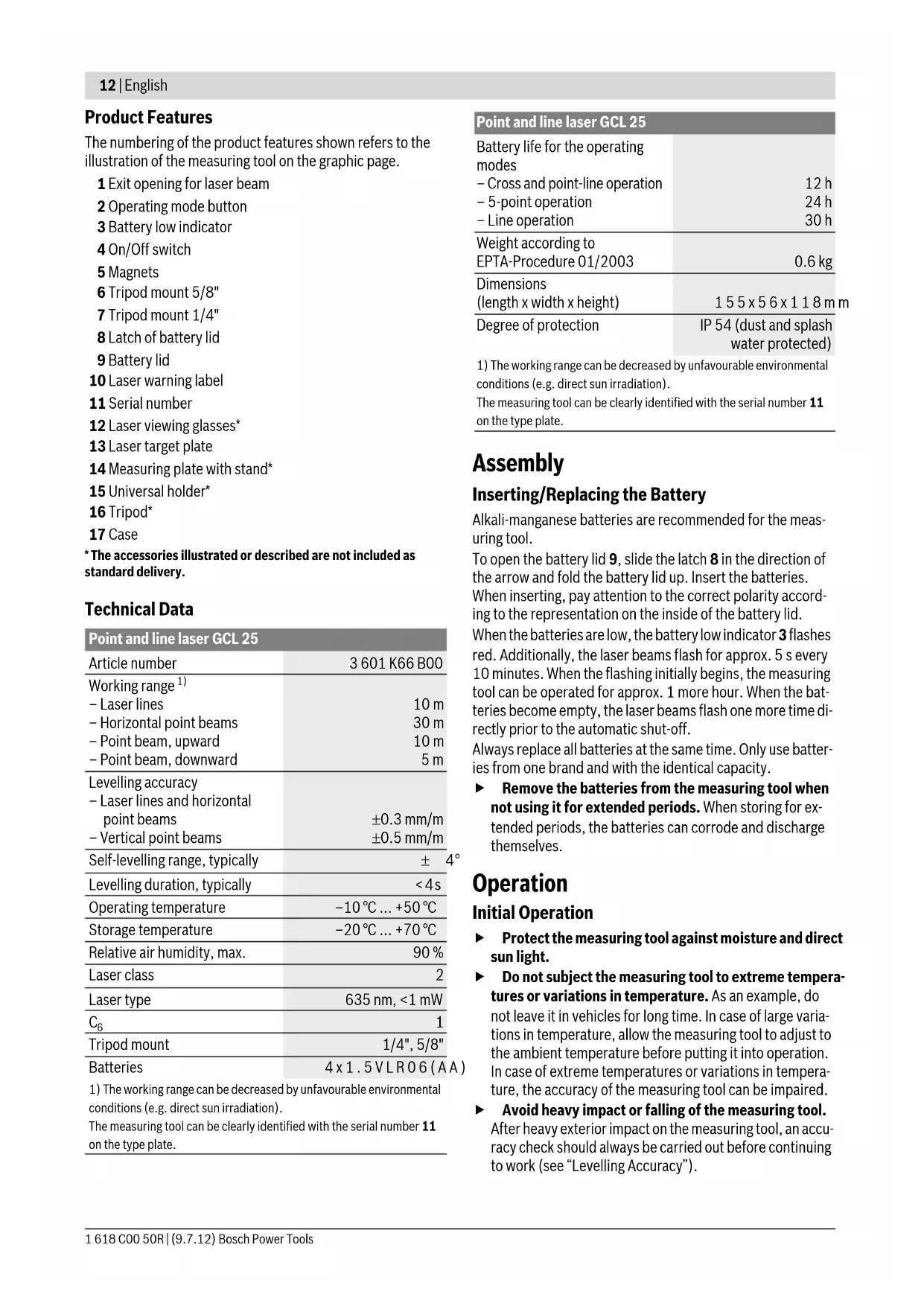
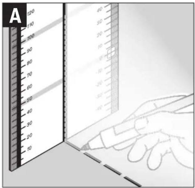
Working with the Measuring Plate (Accessory) (see figures A–B)
With the measuring plate 14, it is possible to project the laser mark onto the floor or the laser height onto a wall.
With the zero field and the scale, the offset or drop to the required height can be measured and projected at another location. This eliminates the necessity of precisely adjusting the measuring tool to the height to be projected.
The measuring plate 14 has a reflective coating that enhances the visibility of the laser beam at greater distances or in intense sunlight. The brightness intensification can be seen only when viewing, parallel to the laser beam, onto the measuring plate.
Working with the Laser Target Plate
The laser target plate 13 increases the visibility of the laser beam under unfavourable conditions and at large distances. The reflective part of the laser target plate 13 improves the visibility of the laser line. Thanks to the transparent part, the laser line is also visible from the back side of the laser target plate.
Laser Viewing Glasses (Accessory)
The laser viewing glasses filter out the ambient light. This makes the red light of the laser appear brighter for the eyes.
▶ Do not use the laser viewing glasses as safety goggles.
The laser viewing glasses are used for improved visualisation of the laser beam, but they do not protect against laser radiation.
▶ Do not use the laser viewing glasses as sun glasses or in traffic. The laser viewing glasses do not afford complete UV protection and reduce colour perception.
Work Examples (see figures C - F)
Applicational examples for the measuring tool can be found on the graphics pages.
Always position the measuring tool close to the surface or edge subject to checking, and allow it to level in prior to each measurement.
Always measure the distances between laser beam or laser line and a surface or edge at two points as far as possible away from each other (e.g. with the measurment plate 14).
Maintenance and Service
Maintenance and Cleaning
Store and transport the measuring tool only in the supplied case.
Keep the measuring tool clean at all times.
Do not immerse the measuring tool in water or other fluids.
Wipe off debris using a moist and soft cloth. Do not use any cleaning agents or solvents.
Regularly clean the surfaces at the exit opening of the laser in particular, and pay attention to any fluff of fibres.
If the measuring tool should fail despite the care taken in manufacturing and testing procedures, repair should be carried out by an authorised after-sales service centre for Bosch power tools. Do not open the measuring tool yourself.
In all correspondence and spare parts orders, please always include the 10-digit article number given on the type plate of the measuring tool.
For repairs, only send in the measuring tool in the case.
After-sales Service and Customer Assistance
Our after-sales service responds to your questions concerning maintenance and repair of your product as well as spare parts. Exploded views and information on spare parts can also be found under:
www.bosch-pt.com
Our customer service representatives can answer your questions concerning possible applications and adjustment of products and accessories.
Great Britain
Robert Bosch Ltd. (B.S.C.)
P.O. Box 98
Broadwater Park
North Orbital Road
Denham
Uxbridge
UB 9 5HJ
Tel. Service: +44 (0844) 736 0109
Fax: +44 (0844) 736 0146
E-Mail: boschservicecentre@bosch.com
Ireland
Origo Ltd.
Unit 23 Magna Drive
Magna Business Park
City West
Dublin 24
Tel. Service: +353 (01) 4 66 67 00
Fax: +353 (01) 4 66 68 88
Australia, New Zealand and Pacific Islands
Robert Bosch Australia Pty. Ltd.
Power Tools
Locked Bag 66
Clayton South VIC 3169
Customer Contact Center
Inside Australia:
Phone: +61 (01300) 307 044
Fax: +61 (01300) 307 045
Inside New Zealand:
Phone: +64 (0800) 543 353
Fax: +64 (0800) 428 570
Outside AU and NZ:
Phone: +61 (03) 9541 5555
www.bosch.com.au
Republic of South Africa
Customer service
Hotline: +27 (011) 6 51 96 00
Gauteng - BSC Service Centre
35 Roper Street, New Centre
Johannesburg
Tel.: +27 (011) 4 93 93 75
Fax: +27 (011) 4 93 01 26
E-Mail: bsctools@icon.co.za
KZN - BSC Service Centre
Unit E, Almar Centre
143 Crompton Street
Pinetown
Tel.: +27 (031) 7 01 21 20
Fax: +27 (031) 7 01 24 46
E-Mail: bsc.dur@za.bosch.com
Western Cape - BSC Service Centre
Democracy Way, Prosperity Park
Milnerton
Tel.: +27 (021) 5 51 25 77
Fax: +27 (021) 5 51 32 23
E-Mail: bsc@zsd.co.za
Bosch Headquarters
Midrand, Gauteng
Tel.: +27 (011) 6 51 96 00
Fax: +27 (011) 6 51 98 80
E-Mail: rbsa-hq.pts@za.bosch.com
People's Republic of China
China Mainland
Bosch Power Tools (China) Co., Ltd.
567, Bin Kang Road
Bin Jiang District 310052
Hangzhou, P.R.China
Service Hotline: 400 826 8484
Fax: +86 571 8777 4502
E-Mail: contact.ptcn@cn.bosch.com
www.bosch-pt.com.cn
HK and Macau Special Administrative Regions
Robert Bosch Hong Kong Co. Ltd.
21st Floor, 625 King's Road
North Point, Hong Kong
Customer Service Hotline: +852 2101 0235
Fax: +852 2590 9762
E-Mail: info@hk.bosch.com
www.bosch-pt.com.hk
Indonesia
PT. Multi Mayaka
Kawasan Industri Pulogadung
Jalan Rawa Gelam III No. 2
Jakarta 13930
Indonesia
Tel.: +62 (21) 46 83 25 22
Fax: +62 (21) 46 82 86 45/68 23
E-Mail: sales@multimayaka.co.id
www.bosch-pt.co.id
Philippines
Robert Bosch, Inc.
28th Floor Fort Legend Towers,
3rd Avenue corner 31st Street,
Fort Bonifacio Global City,
1634 Taguig City, Philippines
Tel.: +63 (2) 870 3871
Fax: +63 (2) 870 3870
matheus.contiero@ph.bosch.com
www.bosch-pt.com.ph
Bosch Service Center:
9725-27 Kamagong Street
San Antonio Village
Makati City, Philippines
Tel.: +63 (2) 899 9091
Fax: +63 (2) 897 6432
rosalie.dagdagan@ph.bosch.com
Malaysia
Robert Bosch (S.E.A.) Sdn. Bhd.
No. 8A, Jalan 13/6
G.P.O. Box 10818
46200 Petaling Jaya
Selangor, Malaysia
Tel.: +60 (3) 7966 3194
Fax: +60 (3) 7958 3838
cheehoe.on@my.bosch.com
Toll-Free: 1800 880 188
www.bosch-pt.com.my
Thailand
Robert Bosch Ltd.
Liberty Square Building
No. 287, 11 Floor
Silom Road, Bangrak
Bangkok 10500
Tel.: +66 (2) 6 31 18 79 - 18 88 (10 lines)
Fax: +66 (2) 2 38 47 83
Robert Bosch Ltd., P. O. Box 2054
Bangkok 10501, Thailand
Bosch Service – Training Centre
2869-2869/1 Soi Ban Kluay
Rama IV Road (near old Paknam Railway)
Prakanong District
10110 Bangkok
Thailand
Tel.: +66 (2) 6 71 78 00 - 4
Fax: +66 (2) 2 49 42 96
Fax: +66 (2) 2 49 52 99
Singapore
Robert Bosch (SEA) Pte. Ltd.
11 Bishan Street 21
Singapore 573943
Tel.: +65 6571 2772
Fax: +65 6350 5315
leongheng.leow@sg.bosch.com
Toll-Free: 1800 333 8333
www.bosch-pt.com.sg
Vietnam
Robert Bosch Vietnam Co. Ltd
10/F, 194 Golden Building
473 Dien Bien Phu Street
Ward 25, Binh Thanh District
84 Ho Chi Minh City
Vietnam
Tel.: +84 (8) 6258 3690 ext. 413
Fax: +84 (8) 6258 3692
hieu.lagia@vn.bosch.com
www.bosch-pt.com
Disposal
Measuring tools, accessories and packaging should be sorted for environmental-friendly recycling.
Do not dispose of measuring tools and batteries/rechargeable batteries into household waste!
Only for EC countries:
According to the European Guideline 2002/96/EC, measuring tools that are no longer usable, and according to the European Guideline 2006/66/EC, defective or used battery packs/batteries, must be collected separately and disposed of in an environmentally correct manner.
Batteries no longer suitable for use can be directly returned at:
Great Britain
Robert Bosch Ltd. (B.S.C.)
P.O. Box 98
Broadwater Park
North Orbital Road
Denham
Uxbridge
UB 9 5HJ
Tel. Service: +44 (0844) 736 0109
Fax: +44 (0844) 736 0146
E-Mail: boschservicecentre@bosch.com
Subject to change without notice.
Français
Robert Bosch (France) S.A.S.
40 m x ± 0.3 mm/m = ±12 mm.
40 m x ± 0.3 mm/m = ±12 mm.
Bosch Service Center
Telegrafvej 3
2750 Ballerup
Tlf. Service Center: +45 (4489) 8855
Fax: +45 (4489) 87 55
E-Mail: vaerktoej@dk.bosch.com
Bortskaffelse
Bosch Service Center
Telegrafvej 3
2750 Ballerup
Danmark
Tel.: +46 (020) 41 44 55
Fax: +46 (011) 18 76 91
Avfallshantering
Bosch San. ve Tic. A.S.
Ahi Evran Cad. No:1 Kat:22
Polaris Plaza
80670 Maslak/Istanbul
Bosch Uzman Ekibi +90 (0212) 367 18 88
Işıklar LTD.ŞTİ.
Kızılay Cad. No: 16/C Seyhan
Adana
Tel.: 0322 359 97 10
Tel.: 0322 359 13 79
Robert Bosch Sp. z o.o.
40 m x ± 0.3 mm/m = ±12 mm.
Bosch Service Center PT
K Vápence 1621/16
692 01 Mikulov
Tel.: +420 (519) 305 700
Fax: +420 (519) 305 705
E-Mail: servis.naradi@cz.bosch.com
www.bosch.cz
Zpracování odpadů
- Okrenite merni alat za oko 180°, ne menjajući visinu. Pustite da se nivelira i označite sredinu tačke drugog bočnog laserskog zraka na zidu (tačka II). Pazite na to, da tačka II bude što vertikalnija iznad odnosno ispod tačke I.
- Razlika d obe označene tačke I i II na zidu daje stvarno visinsko odstupanje mernog alata duž poprečne ose.
Na mernoj liniji od 2 x 20 m = 40 m iznosi maksimalno dozvoljeno odstupanje:
40 m x ± 0,3 mm/m = ±12 mm.
Razlika d izmedju tačaka I i II sme na kraju najviše iznositi 12 mm.
Kontrola horizontalne tačnosti dužne ose
Za kontrolu potrebna Vam je jedna slobodna merna linija od 20 m na čvrstoj podlozi izmedju dva zida A i B.
- Montirajte merni alat blizu zida A na držač ili stativ, ili ga postavite na neku čvrstu i ravnu podlogu. Uključite merni alat i birajte rad sa 5-tačaka.
- Usmerite horizontalan laserski zrak koji ide paralelno sa dužnom osom mernog alata, na bliski zid A. Pustite da se merni alat niveliše. Označite sredinu laserske tačka na zidu (tačka I).
- Okrenite merni alat za 180°, iznivelišite ga i markirajte sredinu tačke laserskog zraka na zidu preko puta B (tačka II).
- Postavite merni alat ne okrećući ga blizu zida B, uključite ga i pustite da se niveliše.
– Centrirajte merni alat po visini tako (pomoću stativa ili u datom slučaju sa podmetačima), da sredina tačke laserskog zraka tačno pogadja prethodno markiranu tačku II na zidu B.
- Okrenite merni alat za 180° ne menjajući visinu. Pustite da se niveliše i označite tačkastu sredinu laserskog zraka na zidu A (tačka III). Pazite pritom, da je tačka III što vertikalnija odnosno nalazi se ispod tačke I.
- Razlika d obe označene tačke I i III na zidu A daju stvarno visinsko odstupanje mernog alata duž dužne ose.
Na mernoj liniji od 2 x 20 m = 40 m iznosi maksimalno dozvoljeno odstupanje:
40 m x ± 0,3 mm/m = ±12 mm.
Razlika d izmedju tačaka I i III sme na kraju da iznosi najviše 12 mm.
Uputstva za rad
Upotrebljavajte uvek samo sredinu laserske tačke odnosno laserske linije za markiranje. Veličina laserske tačke odnosno širina laserske linije menjaju se sa rastojanjem.
Radovi sa stativom (pribor)
Jedan stativ pruža stabilnu mernu podlogu koja se može podešavati po visini. Stavite merni alat sa 1/4" prihvata za stativ 7 na navoj stativa 16 ili jednog uobičajenog u trgovini foto stativa. Za pričvršćivanje na jednom u trgovini uobičajenog gradjevinskog stativa potreban Vam je 5/8" prihvat za stativ 6. Čvrsto zavrnite merni alat sa zavrtnjem za pričvršćivanje stativa.
Centrirajte stativ grubo, pre nego što uključite merni alat.
- Okrenite mjerni alat za cca. 180°, bez promjene visine. Iznivelirajte ga i označite sredinu točke druge bočne laserske zrake na zidu (točka II). Kod toga pazite da točka II po mogućnosti leži okomito, iznad odnosno ispod točke I.
40 m x ± 0.3 mm/m = ±12 mm.
40 m x ±0.3 mm/m = ±12 mm.
Jalan Rawa Gelam III No. 2
Jakarta 13930
Indonesia
Tel.: +62 (21) 46 83 25 22
Fax: +62 (21) 46 82 86 45/68 23
E-Mail: sales@multimayaka.co.id
www.bosch-pt.co.id
Cara membuang
40 m x ±0.3 mm/m = ±12 mm.
Tàng 10,194 Golden Building
473 Điện Biên Phú


- Deutsch
- Sicherheitshinweise
- Product Description and Specifications
- Intended Use
- Product Features
- Technical Data
- Assembly
- Inserting/Replacing the Battery
- Operation
- Initial Operation
- Switching On and Off
- Deactivating the Automatic Shut-off
- Operating Modes
- Automatic Levelling
- Working with Automatic Levelling (see figures C–E)
- Working without Automatic Levelling (see figure F)
- Levelling Accuracy
- Influences on Accuracy
- Checking the Horizontal Levelling Accuracy of the Lateral Axis
- Checking the Horizontal Levelling Accuracy of the Longitudinal Axis
- Working Advice
- Working with the Tripod (Accessory)
- Fastening with the Universal Holder (Accessory)
- Working with the Measuring Plate (Accessory) (see figures A–B)
- Working with the Laser Target Plate
- Laser Viewing Glasses (Accessory)
- Work Examples (see figures C - F)
- Maintenance and Service
- Maintenance and Cleaning
- After-sales Service and Customer Assistance
- www.bosch-pt.com
- Great Britain
- Ireland
- Australia, New Zealand and Pacific Islands
- Republic of South Africa
- Customer service
- Gauteng - BSC Service Centre
- KZN - BSC Service Centre
- Western Cape - BSC Service Centre
- Bosch Headquarters
- People's Republic of China
- China Mainland
- HK and Macau Special Administrative Regions
- Indonesia
- Philippines
- Malaysia
- Thailand
- Singapore
- Vietnam
- Disposal
- Only for EC countries:
- Français
- Bortskaffelse
- Avfallshantering
- Zpracování odpadů
- Kontrola horizontalne tačnosti dužne ose
- Uputstva za rad
- Radovi sa stativom (pribor)
- Cara membuang
Brand : BOSCH
Model : GCL 25 Professional
Category : Laser level