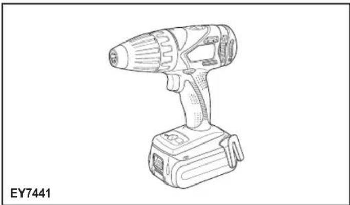
EY7441 - Drill PANASONIC - Free user manual and instructions
Find the device manual for free EY7441 PANASONIC in PDF.
| Product Type | Cordless Drill/Driver |
| Brand | Panasonic |
| Model | EY7441 |
| Motor Voltage | 14.4 V |
| No-load Speed (Low) | 70 - 400 min⁻¹ |
| No-load Speed (High) | 200 - 1400 min⁻¹ |
| Chuck Capacity | 1.5 mm - 13 mm |
| Torque Setting (Clutch) | 18 settings, approx. 0.5 N·m to 4.4 N·m |
| Drilling Capacity (Wood) | 35 mm |
| Drilling Capacity (Metal) | 13 mm |
| Screwdriving Capacity (Wood Screws) | 6.8 mm |
| Screwdriving Capacity (Machine Screws) | M5 |
| Overall Length | 193 mm |
| Weight (with Battery EY9L47) | 1.75 kg |
| Battery Type | Lithium-ion, 14.4 V (models EY9L47, EY9L51, etc.) |
| Compatible Charger | Dedicated Panasonic charger (0°C to 40°C) |
| Main Functions | Drilling, screwdriving with clutch, forward/reverse, LED light, speed selector (low/high) |
| Protection | Overheat protection, battery protection against excessive discharge |
| Maintenance and Cleaning | Clean with a dry, clean cloth. Do not use water, solvent, or volatile products. |
| Safety | Use only original Panasonic battery. Lock the switch after use. Do not inhale fumes. |
| Spare Parts and Repairability | Contact an authorized Panasonic service center for any repairs. |
Frequently Asked Questions - EY7441 PANASONIC
User questions about EY7441 PANASONIC
0 question about this device. Answer the ones you know or ask your own.
Ask a new question about this device
Download the instructions for your Drill in PDF format for free! Find your manual EY7441 - PANASONIC and take your electronic device back in hand. On this page are published all the documents necessary for the use of your device. EY7441 by PANASONIC.
USER MANUAL EY7441 PANASONIC
Cordless Drill & Driver/Cordless Hammer Drill & Driver/Cordless Auto Drill&Driver
Akku-Bohrschrauber/Akku-Schlagbohrschrauber/Akku-Auto Bohrschauber Perceuse-visseuse sans fil/Perceuse a percussion-visseuse sans fil/Perceuse-visseuse automatique sans fil Trapano avitatore cordless/Trapano avitatore cordless a percussion/Trapano Avitatore Cordless a Cambio Automatico Snoerloze schroef-boormachine/Snoerloze slagschroef-boormachine/Snoerloze auto schroef-boormachine Destornillador y taladro sin cables/Destornillador y taladro percutor sin cables/Taladro y destornillador automatico inalambrio Akku bor & skruetrækker/Akku hammerbor & skruertrækker/Akku Auto Bor & Skruetrækker Sladdllos skruvdragare & bormaskin/slagbormaskin/Tradios Automatisik Borr & Skruvdragare Ledninglas drill og skrutrekker/Ledningles slagdril og skrutrekker/Kabellos automatigret drill og trekker Ladattava para & nuvinwanninVladattava vasaraporapora & nuvinwanninLadattava automatinen para & nuvinwannin Kablosuz Matkap ve Tahrik Birimi/Kablosuz Cekic ve Tahrik Birimi/Kablosuz Otomatik Matkap ve Tahrik Birimi Bezprzewodowa wierlarko-wkrelkara/Bezpzewodowa milo-wierlarko-wkrelkara/Bezpzewodowa automatzna wierlarko-wkrelkara Aku vrtacka a sroubovak/Aku vrtaci kladivo a sroubovak/Aku auto vrtacka a sroubovak Akumulatoros furo es cavarbehuzoAkkumulatoros furkaapacis es cavarbehuzoAkkumulatoros automata furo es cavarbehuzo Aku vrtacka a skrutkovaAku vrtace kladivo a skrutkovaAutomaticicka aku vrtacka a skrutkovaAkkumulatorski vrtalin v jvacnik/Akkumulatorski udami vrtalin i jvacnik/Akkumulatorski avtomaticni vrtalin in jvacnik Masjin de gaurit s ingurbat cu accumulator/Clocan rotopercutor cu accumulator/Masina automata de gaurit s ingunbat cu accumulator Berbequim Sem Fios e MotorBerbequim de Percussao Sem Fios e MotorBerbequim Automatico Sem Fios e Motor
Model No: EY7441/EY7940/EY7443/EY74A1/EY7451
EN: Before operating this unit, please read these instructions completely and save this manual for future use.
NOTE: Not all battery packs display the alignment mark (F).
Off (normal operation)
Illuminated: Overheat (motor)
Lyser: Overophedning (motor)
Lyser: Overhettning (motor)
Lyser: Overopbehing (motor)
Flashing: Overheat (battery)
Clignotant: Surchauffe (battery)
Off (normal operation)
Flashing (No charge) Battery protection feature active
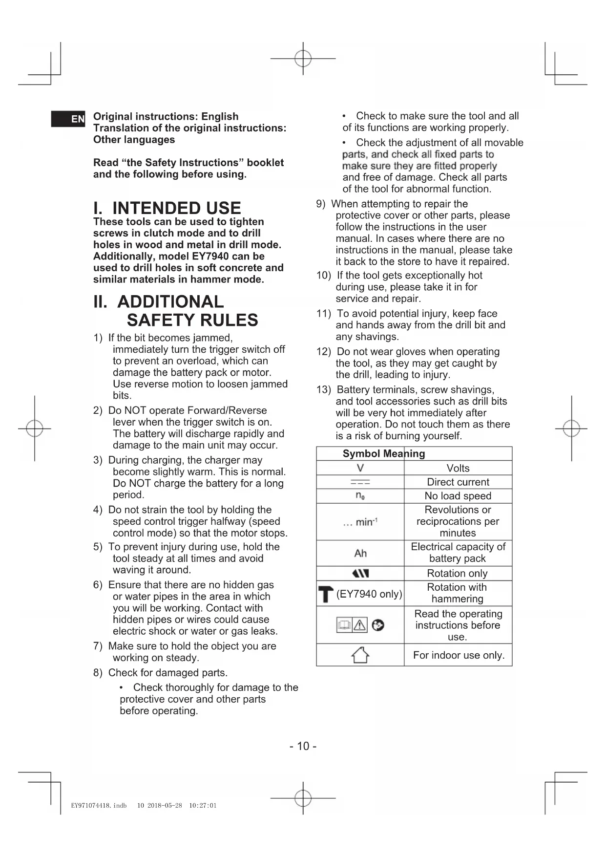
Original instructions: English Translation of the original instructions: Other languages
Read "the Safety Instructions" booklet and the following before using.
I. INTENDED USE
These tools can be used to tighten screws in clutch mode and to drill holes in wood and metal in drill mode. Additionally, model EY7940 can be used to drill holes in soft concrete and similar materials in hammer mode.
II. ADDITIONAL SAFETY RULES
1) If the bit becomes jammed, immediately turn the trigger switch off to prevent an overload, which can damage the battery pack or motor. Use reverse motion to loosen jammed bits.
2) Do NOT operate Forward/Reverse lever when the trigger switch is on. The battery will discharge rapidly and damage to the main unit may occur.
3) During charging, the charger may become slightly warm. This is normal. Do NOT charge the battery for a long period.
4) Do not strain the tool by holding the speed control trigger halfway (speed control mode) so that the motor stops.
5) To prevent injury during use, hold the tool steady at all times and avoid waving it around.
6) Ensure that there are no hidden gas or water pipes in the area in which you will be working. Contact with hidden pipes or wires could cause electric shock or water or gas leaks.
7) Make sure to hold the object you are working on steady.
8) Check for damaged parts. Check thoroughly for damage to the protective cover and other parts before operating.
- Check to make sure the tool and all of its functions are working properly.
- Check the adjustment of all movable parts, and check all fixed parts to make sure they are fitted properly and free of damage. Check all parts of the tool for abnormal function.
9) When attempting to repair the protective cover or other parts, please follow the instructions in the user manual. In cases where there are no instructions in the manual, please take it back to the store to have it repaired.
10) If the tool gets exceptionally hot during use, please take it in for service and repair.
11) To avoid potential injury, keep face and hands away from the drill bit and any shavings.
12) Do not wear gloves when operating the tool, as they may get caught by the drill, leading to injury.
13) Battery terminals, screw shavings, and tool accessories such as drill bits will be very hot immediately after operation. Do not touch them as there is a risk of burning yourself.
| Symbol Meaning | |
| V | Volts |
| --- | Direct current |
| n₀ | No load speed |
| ... min-1 | Revolutions or reciprocations per minutes |
| Ah | Electrical capacity of battery pack |
| ←| | Rotation only |
| (T(EY7940 only) | Rotation with hammering |
| Read the operating instructions before use. | |
| For indoor use only. | |

WARNING
- Do not use other than the Panasonic battery packs that are designed for use with this rechargeable tool.
- Panasonic is not responsible for any damage or accident caused by the use of recycled or counterfeit battery pack.
- Do not dispose of the battery pack in a fire, or expose it to excessive heat.
- Do not allow metal objects to touch the battery pack terminals.
- Do not carry or store the battery pack in the same container as nails or similar metal objects.
- Do not charge the battery pack in a high-temperature location, such as next to a fire or in direct sunlight. Otherwise, the battery may overheat, catch fire, or explode.
- After removing the battery pack from the tool or the charger, always reattach the pack cover. Otherwise, the battery contacts could be shorted, leading to a risk of fire.
- When the Battery Pack Has Deteriorated, Replace It with a New One. Continued use of a damaged battery pack may result in heat generation, ignition or battery rupture.
-
To prevent leakage, overheating, smoke generation, fire, and rupturing from occurring, follow these instructions when handling our rechargeable power tools (tool main body/battery pack/charger).
-
Do not allow material cuttings or dust to fall onto the battery pack.
- Before storing, remove any material cuttings and dust from the battery pack, fit red plastic "terminal cover", then place separately from metal objects (screws, nails, etc.) in tool case. Damage caused by loose objects in the case will not be covered by warranty.
- Do not handle the rechargeable power tools in the following way.
(There is a hazard of smoke generation, fire, and rupturing)
- Use or leave in places exposed to rain or moisture
- Use submerging in water
III. ASSEMBLY
Attaching or Removing Bit NOTE:
When attaching or removing a bit, disconnect battery pack from the main unit or place the switch in the center position (switch lock).
The main unit is equipped with a keyless drill chuck.
- Attachment
Insert the bit and turn the lock collar clockwise (looking from the front) to tighten firmly until it stops clicking. [Fig.1]
- Removal
Turn the lock collar counterclockwise (looking from the front), then remove the bit. [Fig.2]
NOTE:
If there is excessive play in the chuck, secure the drill in place and open the chuck jaws by turning the lock collar and tighten the screw (left-handed screw) with a screwdriver by turning it counterclockwise (viewed from the front). [Fig.3]
Attaching or Removing Battery Pack
- To attach the battery pack: [Fig.4] Align the highlighted marker points and attach battery pack. Slide the battery pack until it locks into position.
- To remove the battery pack: [Fig.4] Push the button and slide the battery pack forward.
EN IV. OPERATION
WARNING!
- Do not inhale smoke emitted from the main unit or battery pack as it may be harmful.
[Main Unit]
CAUTION
When storing or carrying the tool, set the Forward/Reverse lever to the center position (switch lock).
NOTE:
Exercise caution to ensure no objects come into contact with the tool's trigger switch. If an object comes into contact with the tool's trigger switch, even while the Forward/Reverse lever is in the center position (locked), a small amount of electric current may continue flowing, which may cause an excessive discharge from the battery pack and subsequent battery pack failure.
Switch and Forward/Reverse Lever Operation [Fig.5]
- Push the lever for forward or reverse rotation. Check the direction of the lever before using.
- Depress the trigger switch slightly to start the tool slowly.
- Speed will increase by pressing the trigger. The tool stops working immediately by releasing the trigger.
- When done with an application, lock the switch by centering the lever.
NOTE:
When the brake operates, a braking sound may be heard. This is normal.
CAUTION:
When operating the tool by pulling the trigger, there may be a momentary lag before rotation starts. This does not signal a malfunction.
- This lag occurs as the tool's circuitry starts up when the trigger is pulled for the first time after installing a battery pack or after the tool has not been used for at least 1 minute (or at least 5 minutes when the LED is on). Rotation will start without any lag during second and subsequent operations.
CAUTION:
To prevent damage, do not operate Forward/Reverse lever until the bit comes to a complete stop.
Clutch Torque Setting
Adjust the torque to one of the 18 clutch settings or "E", T (EY7940 only) position.
CAUTION:
- Set the clutch setting at this mark [Fig.6] before actual operation.
- If the clutch handle cannot be set at "drilling" mode after driving with clutch function, set the clutch handle at position 1 and operate the clutch for a second.
Speed Selection
Choose a low or high speed to suit the use. (EY7441, EY7940, EY74A1, EY7451) [Fig.7]
Choose a low, high or auto speed to suite the use (EY7443) [Fig.8]
The more the variable speed control trigger is pulled, the higher the speed becomes.
The EY7443 offers AUTO mode, which detects the load on the tool and automatically switches between HIGH and LOW speed operation.
When the load is low, the tool always starts operation in HIGH speed.
When the tightening torque increases, the tool switches to LOW speed. Keep a secure grip on the tool so that it doesn't twist out of your hands due to the increased torque.
When operating in AUTO mode, whether and when the tool switches between HIGH and LOW speed operation will depend on the specific work conditions. These variations in tool behavior are normal and do not represent a malfunction.
NOTE: When selecting AUTO on the EY7443
During AUTO mode operation, the tool may switch to LOW speed under light loads if there is little remaining battery life or if the battery pack temperature is low (0^ or less). In this case, charge the battery pack or place the battery pack in a warm location for at least one hour to allow it to warm up before use. Depending on the load, the tool may switch back and forth between HIGH and LOW speed operation multiple times. If this switching is undesirable, set the tool to HIGH or LOW speed manually.
CAUTION:
- Check the speed selector switch before use.
- Use in low gear when high torque is required in operation. (Using in high gear with high load can cause motor overload and possible failure.)
- To prevent excessive temperature increase of the tool surface, do not operate the tool continuously using two or more battery packs. The tool needs cool-off time before switching to another pack.
- Ensure that air vents on the sides of the main unit are not blocked during operation. Covering them can cause the tool to overheat and motor damage to occur.
- Do NOT strain the tool (motor). This may cause damage to the tool.
- Avoid contact with air from vent holes during operation as under heavy load this can become hot and potentially cause injury.
Bit-locking Function [Fig.9]
- With the trigger switch not depressed and a screwdriver bit locked in place, the tool can be used as a manual screwdriver (up to 22.6 N·m, 230 kgf·cm, 199 in·lbs).
There will be a little play in the chuck, but this is not a malfunction.
- This feature is handy for tightening screws that require more torque than the maximum torque of the driver (position on the clutch), for confirming the tightness of a screw or to loosen an extremely tight screw.
Changing the Belt Hook Location Side [Fig.10]
The belt hook can be attached to either side of the unit.
- Removing the hook
(1) Remove the nut.
(2) Draw out the hook.
- Attaching the hook to the other side
(1) Insert the hook in the other side.
(2) Tighten the nut fully so that it securely fastened.
WARNING!
- Be sure to attach the belt hook securely to the main unit with the screw firmly fastened. When the belt hook is not firmly attached to the main unit, the hook may disconnect and the tool may fall. This may result in an accident or injury.
Periodically check screw for tightness. If found to be loose, tighten firmly.
Be sure to attach the belt hook firmly and securely onto a waist belt or other belt. Pay attention that the tool does not slip off the belt. This may result in an accident or injury.
- When the tool is held by the belt hook, avoid jumping or running with it. Doing so may cause the hook to slip and the tool may fall. This may result in an accident or injury.
- When the tool is hooked onto the waist belt by the belt hook, do not attach driver bits to the tool. A sharp edge object, such as a drill bit, may cause injury or an accident.
EN
EN Control Panel [Fig.11]
(1) LED light [Fig.12]
Before the use of LED light, always pull the power switch once.
Press the LED light button.
The light illuminates with very low current, and it does not adversely affect the performance of the tool during use or its battery capacity.
CAUTION:
- The built-in LED light is designed to illuminate the small work area temporarily.
- Do not use it as a substitute for a regular flashlight, since it does not have enough brightness.
LED light turns off when the tool has not been used for 5 minutes.
Caution: DO NOT STARE INTO BEAM. Use of controls or adjustments or performance of procedures other than those specified herein may result in hazardous radiation exposure.
(2) Overheat warning lamp [Fig.13]
Indicates operation has been halted due to motor or battery overheating.
To protect the motor or battery, be sure to note the following when carrying out this operation.
- If the motor or battery becomes hot, the protection function will be activated and the motor or battery will stop operating. The overheat warning lamp on the control panel illuminates or flashes when this feature is active.
If the overheating protection feature activates, allow the tool to cool thoroughly (at least 30 minutes). The tool is ready for use when the overheat warning lamp goes out. -
Avoid using the tool in a way that causes the overheating protection feature to activate repeatedly.
-
If the tool is operated continuously under high-load conditions or if it is used in hot-temperature conditions (such as during summer), the overheating protection feature may activate frequently.
- If the tool is used in cold-temperature conditions (such as during winter) or if it is frequently stopped during use, the overheating protection feature may not activate.
The performance of the EY9L42 deteriorates significantly at and below 10^ due to work conditions and other factors.
(3) Battery low warning lamp [Fig.14, 15]
Excessive (complete) discharging of lithium ion batteries shortens their service life dramatically. The driver includes a battery protection feature designed to prevent excessive discharging of the battery pack.
- The battery protection feature activates immediately before the battery loses its charge, causing the battery low warning lamp to flash.
- If you notice the battery low warning lamp flashing, charge the battery pack immediately.
- If it is started with too little battery power remaining, the tool may stop operating without the battery low warning lamp flashing first. This indicates that there is too little battery power remaining to use the tool, and the battery pack should be charged before further use.
- If the tool is subject to a sudden load during use that causes the motor to lock up, the overdischarge prevention sensor may be triggered, and the battery low warning lamp may flash. The lamp will stop flashing once you address the cause of the motor's locking up and cycle the trigger.
- The battery protection feature may activate when a high load is abruptly placed on the motor, even if ample battery charge remains. In this case, both the battery low warning lamp and LED
light will flash (EY7443, EY74A1).
If both the battery low warning lamp and LED light flash, reduce the force with which you are pushing on the driver or, if using a drill driver, adjust the speed switch to a lower setting (EY7443, EY74A1).
- If the tool does not switch between HIGH and LOW speed operation in AUTO mode, the motor will stop and the battery low warning lamp and the overheat warning lamp will alternately flash. It is not breakdown.
If both lamps alternately flash, depress the trigger again. (EY7443)
[Battery Pack]
For Appropriate Use of Battery Pack [Fig.9]
The rechargeable batteries have a limited life.
- For optimum battery life, store the Li-ion battery pack following use without charging it.
- When operating the battery pack, make sure the work place is well ventilated.
For safe use
- The battery pack is designed to be installed by proceeding two steps for safety. Make sure the battery pack is installed properly to the main unit before use.
If the battery pack is not connected firmly when the switch is switched on, the overheat warning lamp and the battery low warning lamp will flash to indicate that safe operation is not possible, and the main unit will not rotate normally. Connect the battery pack into the unit of the tool until the red or yellow label disappears.
[Battery Charger]
Charging
CAUTION:
1) If the temperature of the battery pack falls approximately below -10^ (14^) , charging will automatically stop to prevent degradation of the battery.
2) The ambient temperature range is between 0^ (32^) and 40^ (104^) . If the battery pack is used when the battery temperature is below 0^ (32^) , the tool may fail to function properly.
3) Use the charger at temperatures between 0^ (32^) and 40^ (104^) , and charge the battery at a temperature similar to that of the battery itself. (There should be no more than a 15^ (59^) difference between the temperatures of the battery and the charging location.)
4) When charging a cool battery pack (below 0^ (32^) ) in a warm place, leave the battery pack at the place and wait for more than one hour to warm up the battery to the level of the ambient temperature.
5) Cool down the charger when charging more than two battery packs consecutively.
6) Do not insert your fingers into contact hole, when holding charger or any other occasions.
7) Unplug the charger when not in use. NOTE:
Your battery pack is not fully charged at the time of purchase. Be sure to charge the battery before use.
How to charge
- Plug the charger into the AC outlet.
NOTE:
Sparks may be produced when the plug is inserted into the AC power supply, but this is not a problem in terms of safety.
- Connect the battery pack firmly into the charger.
EN
1 Line up the alignment marks and place the battery onto the dock on the charger.
NOTE:
Not all battery packs display the alignment mark (F) (on page 2).
2 Slide forward in the direction of the arrow. [Fig.17]
-
During charging, the charging lamp will be lit. When charging is completed, an internal electronic switch will automatically be triggered to prevent overcharging.
-
Charging will not start if the battery pack is hot (for example, immediately after heavy-duty operation).
The orange standby lamp will be flashing until the battery cools down. Charging will then begin automatically.
-
The charge lamp (green) will flash slowly once the battery is approximately 80% charged.
-
When charging is completed, the charging lamp in green color will turn off.
- If the temperature of the battery pack is 0^ or less, charging takes longer to fully charge the battery pack than the standard charging time.
Even when the battery is fully charged, it will have approximately 50% of the power of a fully charged battery at normal operating temperature.
- Consult an authorized dealer if the charging lamp (green) does not turn off.
- If a fully charged battery pack is inserted into the charger again, the charging lamp lights up. After several minutes, the charging lamp in green color will turn off.
- Remove the battery pack while the battery pack release button is held up.
LAMP INDICATIONS
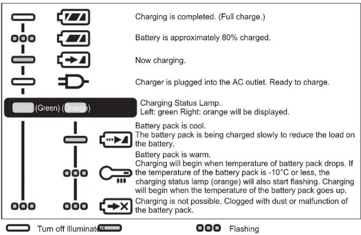
[Fig.17]
Battery Recycling
ATTENTION:
For environmental protection and recycling of materials, be sure that it is disposed of at an officially assigned location, if there is one in your country.
Information for Users on Collection and Disposal of Old Equipment and used Batteries
EN
These symbols on the products, packaging, and/or accompanying documents mean that used electrical and electronic products and batteries should not be mixed with general household waste.
For proper treatment, recovery and recycling of old products and used batteries, please take them to applicable collection points, in accordance with your national legislation and the Directives 2012/19/EC and 2006/66/EC.
By disposing of these products and batteries correctly, you will help to save valuable resources and prevent any potential negative effects on human health and the environment which could otherwise arise from inappropriate waste handling.
For more information about collection and recycling of old products and batteries, please contact your local municipality, your waste disposal service or the point of sale where you purchased the items.
Penalties may be applicable for incorrect disposal of this waste, in accordance with national legislation.
[For business users in the European Union]
If you wish to discard electrical and electronic equipment, please contact your dealer or supplier for further information.
[Information on Disposal in other Countries outside the European Union]
These symbols are only valid in the European Union. If you wish to discard these items, please contact your local authorities or dealer and ask for the correct method of disposal.
V. MAINTENANCE
- Use only a dry, soft cloth for wiping the unit.
Do not use a damp cloth, thinner, benzine, or other volatile solvents for cleaning.
- In the event that the inside of the tool or battery pack is exposed to water, drain and allow to dry as soon as possible. Carefully remove any dust or iron filings that collect inside the tool. If you experience any problems operating the tool, consult with a repair shop.
VI. ACCESSORIES
Use only bits suitable for size of drill's chuck.
VII. APPENDIX
MAXIMUM RECOMMENDED CAPACITIES
| Model EY7441 EY7940 EY7443 EY7451 | EY74A1 | ||||
| Screw driving | Machine screw M5 | ||||
| Wood screwø6,8 mm | |||||
| Drilling | Self-drilling screwø6 mm | ||||
| For Woodø35 mm | |||||
| For Metalø13 mm | |||||
| For Masonry | - | ø13 mm | - | - | |
EN WARRANTY SUPPLEMENT
- The breakdown and damage caused by usage consistent for a long time (e.g.: factory work on the assembly line, etc.) is out of warranty.
- In the event that the inside of the tool or battery pack is exposed to water, drain and allow to dry as soon as possible. Carefully remove any dust or iron filings that collect inside the tool. If you experience any problems operating the tool, consult with a repair shop.
VIII. SPECIFICATIONS
NOTE: Weight indication
Greater than or equal to 1kg : indicated by 0.05kg
Less than 1kg : indicated by 0.01kg
MAIN UNIT
| Model EY7441 EY7940 | EY7443 EY74A1 | EY7451 | |||||
| Motor voltage 14.4 V 14 | 4 V 18 V | 18 V | |||||
| No load speed | Low 70~400 min-1 | 60~400 min-1 | 50~480 min-1 | 80~600 min-1 | 70~400 min-1 | ||
| High 200~1400 min-1 | 160~1400 min-1 | 130~1400 min-1 | 220~1750 min-1 | 200~1400 min-1 | |||
| Auto - | - | 160~1400 min-1 | - | - | - | ||
| Blows Rate Per Minute | Low | - | 1260~7200 min-1 | -- | - | - | |
| High - | 3600~25200 min-1 | -- | - | - | |||
| Chuck capacity | ø1.5 mm~ø13 mm | ||||||
| Clutch torque | Approx 0.5 N·m~4.4 N·m | Approx 1.0 N·m~4.4 N·m | Approx 0.5 N·m~4.4 N·m | Approx 0.5 N·m~0.4 N·m | Approx 0.5 N·m~4.4 N·m | ||
| Overall length | 193 mm | 200 mm | 199 mm | 203 mm | 193 mm | ||
| Weight With battery pack | EY9L45 | 1.75 kg | 1.8 kg | 1.85 kg | 1.85 kg | - | - |
| EY9L47 | 1.55 kg | 1.6 kg | 1.65 kg | 1.65 kg | - | - | |
| EY9L51 | - | - | -- | 1.95 k | g | 1.85 kg | |
| EY9L52 | - | - | -- | 1.75 k | g | 1.65 kg | |
| EY9L53 | - | - | -- | 1.75 k | g | 1.65 kg | |
| EY9L54 | - | - | -- | 2.00 k | g | 1.90 kg | |
| Noise vibration | See the included sheet | ||||||
ONLY FOR U.K. IX. ELECTRICAL PLUG INFORMATION
FOR YOUR SAFETY PLEASE READ THE FOLLOWING TEXT CAREFULLY
This appliance is supplied with a moulded three pin mains plug for your safety and convenience.
A 5 amp fuse is fitted in this plug.
Should the fuse need to be replaced please ensure that the replacement fuse has a rating of 5 amp and that it is approved by ASTA or BSI to BS1362.
Check for the ASTA mark or the BSI mark on the body of the fuse.
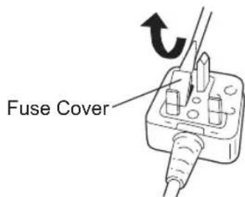
If the plug contains a removable fuse cover you must ensure that it is refitted when the fuse is replaced.
If you lose the fuse cover the plug must not be used until a replacement cover is obtained.
A replacement fuse cover can be purchased from your local Panasonic Dealer.
IF THE FITTED MOULDED PLUG IS UNSUITABLE FOR THE SOCKET OUTLET IN YOUR HOME THEN THE FUSE SHOULD BE REMOVED AND THE PLUG CUT OFF AND DISPOSED OF SAFELY. THERE IS A DANGER OF SEVERE ELECTRICAL SHOCK IF THE CUT OFF PLUG IS INSERTED INTO ANY 13 AMP SOCKET.
If a new plug is to be fitted please observe the wiring code as shown below.
If in any doubt please consult a qualified electrician.
IMPORTANT:
The wires in this mains lead are coloured in accordance with the following code:
Blue: Neutral
Brown:Live
As the colours of the wire in the mains lead of this appliance may not correspond with the coloured markings identifying the terminals in your plug, proceed as follows.
The wire which is coloured BLUE must be connected to the terminal in the plug which is marked with the letter N or coloured BLACK.
The wire which is coloured BROWN must be connected to the terminal in the plug which is marked with the letter L or coloured RED.
Under no circumstances should either of these wires be connected to the earth terminal of the three pin plug, marked with the letter E or the Earth Symbol 1三
How to replace the fuse: Open the fuse compartment with a screwdriver and replace the fuse and fuse cover if it is removable.
This apparatus was produced to BS800.
EN
DE
(2) Overheat warning lamp [Fig.13]
Bedieningspaneel [Fig.11]
(1) LED-lampje [Fig.12]
VIII. TEKNISET TIEDOT
Importer for Turkey:
Panasonic Eco Solutions Elektnik San Tic A.S
Abdurrahmangazi Mah. Eubekir Cad. No: 44
34887 Sancaktepe Istanbul/Turkiye
EN. DE. FR. IT. NL. ES. DA. SV. NO. FI. TR. PL. CS. HU. SK. SL. RO. PT
EY971074418 2018 09 Printed in China